spin shine electric drive repositioning manual · 2020-01-02 · two spin shine wheel brushes (d-s...
TRANSCRIPT

© Motor City Wash Works, Inc. 48285 Frank, Wixom Michigan 48393 U.S.A. Phone: 248.313.0272 ▪ Fax: 248. 313.0271
8MANULSPNDOC001 REV 1.0 www.motorcitywashworks.com 1
SPIN SHINE ELECTRIC DRIVE REPOSITIONING MANUAL Part # 8MANULSPNDOC001
TABLE OF CONTENTS Equipment Utilities Page: 1 Equipment Specifications Page: 1 Suggested Tools and Installation Materials Page: 1 Installation Instructions Page: 2
Equipment Utilities
Equipment Specifications
Two Spin Shine Wheel Brushes (D-S and P-S)
Powder Coated Aluminum Construction
Unique Auto Retract Function
Corrosion Resistant Bearings Throughout Equipment
Hydraulic or Electric Drive
Feather Tipped Brushes
Ultra-Low Lead-In and Exit Guide Rails
151” Tunnel Space Required for the Driver Side Applicator
116” Tunnel Space Required for the Passenger Side Applicator
120 VAC Air Panels
Suggested Installation Tools and Materials
3/8” Allen Head Wrench
8mm Allen Head Wrench
1/2” Allen Head Wrench
3/8” Socket Head Wrench
3/8” Box End Wrench
5/16” Socket Head Wrench
Rubber Mallet
APPLICATOR
SPINSHINE360001 (9ft Electric Drive)
(8ft Electric Drive)
CONTROL PANEL
SYSTEM
7SPINCTLPNL0003 With VFD
7SPINCTLPNL0001 Without VFD
ELECTRICAL SUPPLY: 120VAC, 20A SIGNAL: (3) From CW Controller 24-120VAC/DC
MOTORS: (2)0.75hp 230VAC/1.78FLA-each Powered from MCC SIGNAL: (2) From CW Controller 24-120VAC/DC
PNEUMATICS 2 SCFM @ 100 PSI (max)
HYDRAULIC NOT APPLICABLE

© Motor City Wash Works, Inc. 48285 Frank, Wixom Michigan 48393 U.S.A. Phone: 248.313.0272 ▪ Fax: 248. 313.0271
8MANULSPNDOC001 REV 1.0 www.motorcitywashworks.com 2
WARNING! DANGEROUS SITUATION WHICH MAY CAUSE
EQUIPMENT DAMAGES, PERSONAL INJURIES OR FATALITIES! MAKE SURE MOTOR HAS BEEN DISCONNECTED FROM ELECTRICAL PANEL!
• Remove the cover.
• Remove the (2) 3/8” flat head bolts on the front of the yellow plastic angled cover.
• Remove the (3) 3/8” hex head bolts holding the gearbox cover to the main beam. Then, remove the gearbox cover assembly and use a work bench to start the disassembly process.

© Motor City Wash Works, Inc. 48285 Frank, Wixom Michigan 48393 U.S.A. Phone: 248.313.0272 ▪ Fax: 248. 313.0271
8MANULSPNDOC001 REV 1.0 www.motorcitywashworks.com 3
• Flip the assembly over and remove the (2) 5/16” flat head bolts from the yellow plastic angled cover.
• Remove the (2) 1/2” hex head bolts holding the blue gearbox cover and mount.

© Motor City Wash Works, Inc. 48285 Frank, Wixom Michigan 48393 U.S.A. Phone: 248.313.0272 ▪ Fax: 248. 313.0271
8MANULSPNDOC001 REV 1.0 www.motorcitywashworks.com 4
• Remove the (2) 3/8” hex head bolts holding the mount for the yellow plastic angled cover.
• Remove the (4) 3/8” socket head cap screws from the sub plate.
• Remove the (2) 3/8” hex head bolts from the main plate holding the gusset mount.

© Motor City Wash Works, Inc. 48285 Frank, Wixom Michigan 48393 U.S.A. Phone: 248.313.0272 ▪ Fax: 248. 313.0271
8MANULSPNDOC001 REV 1.0 www.motorcitywashworks.com 5
• Remove the (3) 3/8” hex head bolts from the main plate holding the end plate.
• At this point you are ready to re-assemble. Stand the main plate on its edge and bolt the end plate and
gusset back on the main plate using the (5) 3/8” hex head bolts.
• Bolt the sub plate back on the end plate and gusset plate using the (4) 3/8” socket head cap screws.

© Motor City Wash Works, Inc. 48285 Frank, Wixom Michigan 48393 U.S.A. Phone: 248.313.0272 ▪ Fax: 248. 313.0271
8MANULSPNDOC001 REV 1.0 www.motorcitywashworks.com 6
• Bolt the yellow plastic mount plate back on using the (2) 3/8” hex head bolts.
• Bolt the blue gearbox cover and mount back on the sub plate with the (2) 1/2” hex head bolts.
• Flip the assembly over and bolt the yellow plastic angled cover back on with the (2) 5/16” flat head bolts.

© Motor City Wash Works, Inc. 48285 Frank, Wixom Michigan 48393 U.S.A. Phone: 248.313.0272 ▪ Fax: 248. 313.0271
8MANULSPNDOC001 REV 1.0 www.motorcitywashworks.com 7
• At this time you are ready to rotate the motor/gearbox assembly. Remove the (4) 8mm hex head bolts in the grey end cap.
• Remove the 3/8” hex head bolt, lock washer and flat washer holding the gearbox on the shaft.
• Remove the 1/2” hex head torque bolt from the bearing plate.

© Motor City Wash Works, Inc. 48285 Frank, Wixom Michigan 48393 U.S.A. Phone: 248.313.0272 ▪ Fax: 248. 313.0271
8MANULSPNDOC001 REV 1.0 www.motorcitywashworks.com 8
• Slide the motor/gearbox down the shaft about 1-1/2” (make sure not to slide off of the shaft), this will give you enough room to remove the (4) 8mm hex head bolts holding the torque plate.
• Rotate the torque plate around the gearbox until it gets close to the gearbox motor plate and put the (4)
8mm hex head bolts back in the torque plate.
• Rotate the motor/gearbox so the torque plate 1/2” hex head bolt is on the bottom and thread the bolt in the
new threaded hole on the bearing plate.

© Motor City Wash Works, Inc. 48285 Frank, Wixom Michigan 48393 U.S.A. Phone: 248.313.0272 ▪ Fax: 248. 313.0271
8MANULSPNDOC001 REV 1.0 www.motorcitywashworks.com 9
• Below is what the motor/gearbox assembly should resemble.
• Bolt the motor/gearbox assembly on with the 3/8” hex head bolt, lock washer and flat washer.
• Bolt the gearbox end cap on with the (4) 8mm hex head bolts.
© Motor City Wash Works, Inc. 48285 Frank, Wixom Michigan 48393 U.S.A. Phone: 248.313.0272 ▪ Fax: 248. 313.0271
8MANULSPNDOC001 REV 1.0 www.motorcitywashworks.com 10
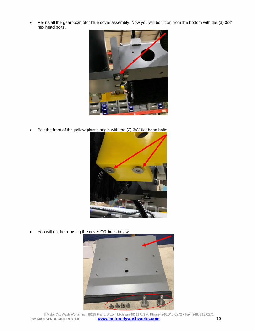
• Re-install the gearbox/motor blue cover assembly. Now you will bolt it on from the bottom with the (3) 3/8” hex head bolts.
• Bolt the front of the yellow plastic angle with the (2) 3/8” flat head bolts.
• You will not be re-using the cover OR bolts below.

© Motor City Wash Works, Inc. 48285 Frank, Wixom Michigan 48393 U.S.A. Phone: 248.313.0272 ▪ Fax: 248. 313.0271
8MANULSPNDOC001 REV 1.0 www.motorcitywashworks.com 11
• Below is what it should look like when you are finished.
WARNING! DANGEROUS SITUATION WHICH MAY CAUSE EQUIPMENT
DAMAGES, PERSONAL INJURIES OR FATALITIES! MAKE SURE MOTOR IS WIRED SECURELY AND CORRECTLY FOR INCOMING VOLTAGE BEFORE RECONNECTING TO ELECTRICAL PANEL!
Always follow all ‘Notes’, ‘Warnings’ and instructions. Not doing so may have serious
consequences on the overall performance of the washing equipment and/or the safety of
the people working on the equipment!
STOP! PRECAUTION TO TAKE TO AVOID EQUIPMENT
MALFUNCTION OR ERROR!
© Motor City Wash Works, Inc. 48285 Frank, Wixom Michigan 48393 U.S.A. Phone: 248.313.0272 ▪ Fax: 248. 313.0271
8MANULSPNDOC001 REV 1.0 www.motorcitywashworks.com 12
Warranty and Return Procedure: Motor City Wash Works warrant this product to be free of defect in material and/or workmanship for a period of
one year from the date of the purchase by the customer from MCWW. During the warranty period MCWW will at
its discretion, at no charge to the customer, repair or replace this product if found defectives, with a new or
refurbished unit, but not to include costs of removal or installation. Any product returned to MCWW for warranty
has to have a Return Material Authorization Number. All shipping cost to MCWW is assumed by the customer.
This is only a summary of MCWW Limited Warranty. Please, communicate with MCWW for our complete
warranty.
Prior to returning any product to MCWW, the customer must call in for Return Material Authorization Number
and a copy of our Return Material Authorization Form filled and completed. The RMA number must be written
clearly on the outside of the shipping package and copy of the form must be included in the package.