specifications for subdivision roads in urban and rural areas · specifications for subdivision...
TRANSCRIPT

r-~--~~ .. ~~~~~--------------------------------------------------'I
: i
Specifications for Subdivision Roads in Urban and Rural Areas
Nova Scotia
:x: Department of Transportation and Communications
Effective May 25, 1989

The intent of these specifications is to insure the design and construction of the subdivision i.n such a manner as to permit the Department of Transportation and Communications to list and maintain the roads therein.

I N D E X
DIVISION 1 - DEFINITION OF TERMS
DIVISION 2 - GENERAL DESIGN SPECIFICATIONS
DIVISION 3 - GENERAL CONSTRUCTION SPECIFICATIONS
DIVISION 4 - CONSTRUCTION SPECIFICATIONS FOR ROADS WITHOUT ASPHALT CONCRETE PAVING AND NOT SERVICED WITH AN UNDERGROUND STORM SEWER SYSTEM
DIVISION 5 - PAVING CONSTRUCTION SPECIFICATIONS FOR ROADS NOT SERVICED WITH AN UNDERGROUND STORM SEWER SYSTEM·
DIVISION 6 - PAVING CONSTRUCTION SPECIFICATIONS FOR ROADS SERVICED WITH AN UNDERGROUND STORM SEWER SYSTEM
DIVISION 7 - VARIATIONS
DIVISION 8 - LISTING PROCEDURES
I ,
SUBDIVISION ROAD SPECIfICATIONS
DIVISION 1
DEfINITION OF TERMS
PAGE 1
Whenever in any part of these Specifications, the following words or expressions or pronouns used in their stead are used, the intent and meaning shall be interpreted as follows:
Department, and Department of Transportation and Communications. The Department of Transportation and Communications of the Province of Nova Scotia. .
Municipality. The Municipality in which the Subdivision is located.
Subdivision. The division of any area of land into two or more parcels, and includes a resubdivision or a consolidation of two or more parcels.
Engineer. The Chief Engineer of' the Department of Transportation and Communications of the Province of Nova Scotia acting directly or through an assistant or representatives, duly authorized by the Chief Engineer, and acting only within the scope of the particular duties assigned to him or within the scope of the authority vested in him.
Highways. The constructing the. determined by the
whole right-of-way which is roadway and .its appurtenances
Department's Engineer.
reserved for use in the boundaries being
Arterial. A road intended to move a relatively large volume of traffic at medium to high speeds used where traffic movement is the primary consideration and land access secondary.
Collector. a road intended to collect traffic from local streets and move it to the arterials, used where traffic movement and land access are of equal importance.
Local. A road which has the main function of providing land access.
Standard Specification. The current edition of the Standard Specification of the Province of Nova Scotia Department of Transportation and Communications. The directions, provisions and requirements as supplemented by special provisions as may be necessary pertain to the design, method and manner of performing the,work, or the quantities and qualities of materials to be furnished.

PAGE 2
Roadway. The portion of highway included between the outside lines of gutters, or side ditches; including all the appertaining structures, and all slopes, ditches channels,' wate;L'Ways, etc. necessary for proper drainage and protection. . -,' ,
Roadbed. shoulder unit.
That portion of the ,roadway extending from shoulder line to line, in other words, the subgrade and shoulders considered as a
Sub grade . That portion of the roadbed upon whic~ the base course is to be placed.
Base Course. The crushed rock or aggregate which' is placed immediately upon the subgrade.
Surfacing. The crushed rock or aggregate which is placed immediately upon the base course.
Approval. The approval of the Engineer. The Engineer's decision will b~, final and binding in matters of design and construction.
Inspections. Field inspection by the En'giIJ,eer at various stages of construction.
Professional Engineer. A Professional Engineer who is a member of the Association of Professional Engineers of Nova Scotia.
DESIGN: "THE FUNCTION OF LOCATING ROADS AND BUILDING LOTS RELATIVE TO TOPOGRAPHICAL FEATURES, CONSTITUTES THE PRACTICE OF ENGINEERING AS DEFINED BY THE ENGINEERING PROFESSION ,ACT OF NOVA SCOTIA. THEREFORE, THE DESIGN OF SUBDIVISIONS AND THEIR SERVICES WHEN SUBMITTED TO THE DEPARTMENT MUST BE OVER THE SEAL OF A PROFESSIONAL ENGINEER."
PAGE 3
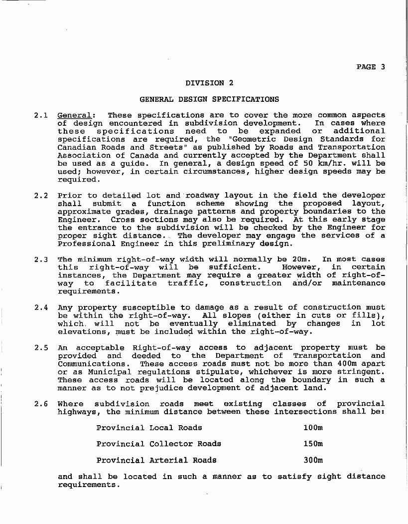
DIVISION 2
GENERAL DESIGN SPECIFICATIONS
2.1 General: These specifications are to cover the more common aspects of design encountered in subdivision development. In cases where these specifications need to be expanded or additional specifications are required, the "Geometric Design Standards for Canadian Roads and Streets" as published by Roads and Transportation Association of Canada and currently accepted by the Department shall be used as a guide. In general, a design speed of 50 km/hr. will be used; however, in certain circumstances, higher design speeds may be required.
2.2 Prior to detailed lot and roadway layout in the field the developer shall submit a function scheme showing the proposed layout, approximate grades, drainage patterns and property boundaries to the Engineer. Cross sections may also be required. At this early stage the entrance to the subdivision will be checked by the Engineer for proper sight distance .. The developer may engage the services of a Professional Engineer in this preliminary design.
2.3 The minimum right-of-way width will normally be 20m. In most cases this right-of-way will be sufficient. However, in certain instances, the Department may require a greater width of right-ofway to facilitate traffic, construction and/or maintenance requirements.
2.4 Any property susceptible to damage as a result of construction must be within the right-of-way. All slopes (either in cuts or fills), which. will not be eventually eliminated by changes in lot elevations, must be include~ within the right-of-way.
2.5 An acceptable Right-of-way access to adjacent property must be provided and deeded to the Department of Transportation and Communications. These access roads must not be more than 400m apart or as Municipal regulations stipulate, whichever is more stringent. These access roads will be located along the boundary in such a manner as to not prejudice development of adjacent land.
2.6 Where subdivision roads meet existing classes of provincial highways, the minimum distance between these intersections shall be:
Provincial Local Roads 100m
Provincial Collector Roads 150m
Provincial Arterial Roads 300m
and shall be located in such a manner as to satisfy sight distance requirements.

PAGE 4
Within the subdivision the minimum distance between intersections of local roads will be 75m measured centre line to centre line.
In general, offset intersections, including pedestrian sidewalks and bike ways shall be no less than 50m apart, measured centre line to centre line.
Sight.distance requirements are as follows:
1
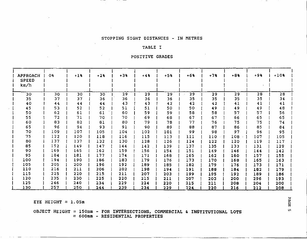
STOPPING SIGHT DISTANCES - IN METRES
TABLE I
POSITIVE GRADES
1
APPROACH 0% +1% 1 +2% +3% 1 +4% 1 +5% +6% +7% +8% +9% 1 +10% SPEED 1 1 1 1
km/h 1 1 1 1
1 1 1 I
30 30 30 I 30 29 1 29 1 29 29 29 29 28 1 28 35 37 37 I 36 36 1 36 1 36 35 35 35 35 1 34 40 44 44 I 44 43 1 43 1 42 42 42 41 41 1 41 45 53 52 1 52 51 1 51 1 50 50 49 49 49 1 48 50 62 61 1 61 60 1 59 1 59 58 58 57 57 1 56 55 72 71 1 70 70 1 69 1 68 67 67 66 65 1 65 60 83 82 1 81 80 I 79 1 78 77 76 75 75 1 74 65 96 94 I 93 91 1 90 1 89 88 87 86 85 1 84 70 109 107 1 105 104 1 102 "I 101 99 98 97 96 1 95 75 122 120 1 118 116 1 115 113 III 110 108 107 1 105 80 137 137 1 132 130 1 128 126 124 122 120 119 1 117 85 152 149 1 147 144 1 142 139 137 135 133 131 1 129 90 169 165 1 162 159 I 156 154 151 149 146 144 I 142 95 184 181 I 177 174 1 171 168 165 162 160 157 I 155
100 194 190 1 186 183 1 179 176 173 170 168 165 1 163 105 205 200 1 196 192 1 189 185 182 179 176 173 1 171 110 216 211 1 206 202 1 198 194 191 188 184 182 1 179 115 225 220 1 215 211 1 207 203 199 195 192 189 1 186 120 235 230 1 225 220 1 215 211 207 203 200 296 1 193 125 246 240 1 234 229 1 224 220 215 211 208 204 I 200 130 257 250 I 244 239 1 234 229 ~24 220 216 212 I 208
EYE HEIGHT = 1.05m
OBJECT HEIGHT = 150mm FOR INTERSECTIONS, COMMERCIAL & INSTITUTIONAL LOTS = 600mm RESIDENTIAL PROPERTIES
g U1
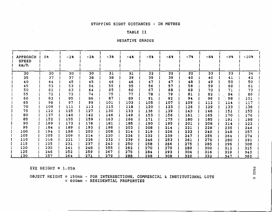
STOPPING SIGHT DISTANCES - IN METRES
TABLE II
NEGATlVE GRADES
APPROACH 1 0% -1% 1 -2% 1 -3% -4% 1 -5% -6% -7% -8% -9% -10% SPEED 1 1 1 1 km/h 1 I 1 1 I 1 I
1 1 1 1 I 1 I 30 1 30 30 1 30 1 31 31 I 32 32 32 33 I 33 1 34 I 35 I 37 37 1 38 I 38 39 I 39 39 40 40 I 41 I 42 I
40 1 44 45 I 45 1 46 46 1 47 47 48 49 I 50 I 50 I 45 1 53 53 1 54 I 55 55 1 56 57 58 59 1 60 1 61 I 50 1 62 63 1 64 1 65 66 I 67 68 69 70 71 1 73 1 55 1 72 73 I 74 1 75 77 I 78 79 81 82 84 1 86 I 60 1 83 85 1 86 1 87 89 1 91 92 94 96 ". 98 1 101 1 65 1 96 97 99 I 101 103 I 105 107 109 112 .114 I 117 1 70 109 III 113 I 115 118 I 120 123 126 129 133 I 136 I
75 122 125 127 I 130 133 I 136 139 143 146 151 I 155 I
80 137 140 142 146 1491 153 156 161 165 170 1 176 1 85 152 155 159 163 166 1 171 175 180 185 191 1 198 1 90 169 173 176 181 185 I 190 195 201 208 214 I 222 1 95 184 189 193 198 203 I 208 1 214 221 228 . 235 1 244 1
100 194 198 203 208 214 I 219 I 226 233 240 248 I 257 1 105 205 209 214 220 226 1 232 I 239 247 255 264 1 274 1 110 216 221 226 232 239 I 246 I 253 261 270 280 I 291 1 115 225 231 237 243 250 I 258 I 266 275 285 296 I 308 I
120 235 241 248 255 262 1 270 I 279 289 300 312 1 325 I 125 246 252 259 267 275 I 284 I 293 304 316 329 I 343 I 130 257 264 271 279 288 I 298' 1 308 320 332 347 1 362 I
EYE HEIGHT = 1.05m
OBJECT HEIGHT = 150mm FOR INTERSECTIONS, COMMERCIAL I< INSTITUTIONAL LOTS = 600mm RESIDENTIAL PROPERTIES
:g ~
'"

r \ I
/'
)
PAGE 7
2.7 Roads must be laid out where reasonably possible in prolongations of other roads, either in the same subdivision or in adjacent subdi visions. Unless there are unique circumstances, the minimum length of road considered for listing will be 150m.
2.8 Due to maintenance problems:
REVISED _ SEE 2.8 DATED DECEMBER 20, 1990. AT BACK OF BOOK
2. Boulevards will not be permitted in residential subdivisions.
2.9 The minimum set back distance to any building will be Sm from the nearest highway boundary, or as Municipal regulations stipulate, whichever specification is more stringent.
2.10 Unless otherwise authorized by the Engineer in writing an acceptable storm drainage study and design must be carried out by a Professional Engineer. This authority will only be given for the most basic subdivision and drainage patterns. The minimum design for major drainage systems such as brooks, streams and rivers must be based on a 1 in 100 year storm. The minimum design for minor drainage systems such as ditches, culverts etc. will be based on a 1 in 5 year frequency. If the Municipali'ty's storm drainage requirements are more stringent than the Departments, the Municipality'S specifications shall prevail.
Roadway culverts, underdrains,· driveway culverts, (see 3.7) and storm drainage systems, where required, will be of a size acceptable to the Department. The Department may recommend the size and location of the drainage culvert, but in no case shall any roadway culvert be less than 500mm in diameter. All roadway culverts must have a minimum cover of 500mm.
All pipe under the roadway shall be C.I.P., reinforced concrete or other material satisfactory to the Department. Where conditions warrant and corrugated metal pipe is being used, the Engineer may require a special treatment of the pipe such as asphalt coating.
All pipe in underground storm sewer systems must be reinforced concrete pipe. Catch basins will be a maximum of 100m apart, and must conform to Standard Specifications, Division 5, Section 27.

No drainage is to be carried on, through or over private property, within the subdivision, other than by unconfined natural water course, by excavated ditch, or storm sewer. To ensure access to drainage systems, title to a tract of land of ample Width shall be conveyed in fee simple absolute to the municipality or the Department of Transportation and Communication in the following cases:
(a)
(b)
Excavated ditches or storm sewers within the boundary of the subdivision.
Where a need is identified to accommodate future upstream drainage, title to a tract of land of ample width for drainage purposes shall be conveyed In fee simple absolute from the roadway to the upstream limits of the subdivIsion .
... and; may be required for excavated offtake ditches or storm sewers adjacent to and immediately downstream of the subdivision that are required to ensure proper funclionlng of the subdivision drainage system.
Land for drainage purposes will not normally be required for an unconfined natural water
course.
A plan must be submitted to the Department showing upstream drainage that must be accommodated, the final drainage pattern within the subdivision and indicating the drainage pattern of subdivision runoff outside the subdivision as it affects abutting land. Where subdivision drainage flows from the subdivision onto abutting property other than in a natural water course, consent in writing of the owner(s) affected, must be filed with the Municipality or the Department of Transportation and Communications and recorded in the Registry of Deeds. Natural water courses shall not normally be carried in roadway ditches or storm sewers.
2.11 All intersecting roads must intersect at an angle of 70 to 90 degrees for a minimum distance of 30m from the intersection measured from the respective centre lines.
2.12 Straight or. gently rolling grades with proper vertical curves are required to provide adequate stopping sight distance, as specified in the "Geometric DeSign Standards for Canadian Roads and Streets", depending upon the design speed. In all cases a profile will be required, showing proposed grades. In general a grade of 6% will be considered to be the maximum allowable, however, in difficult circumstances grades up to 8% may be approved. Grades in excess of 8% will only be approved in exceptional circumstances and with prior approval by the Department. The minimum grade shall be 0.5%. Grades at intersections shall not exceed 2% for at least 15m measured from the shoulder of the intersecting road.
2.13 Side slopes in cuts will be a minimum of 2:1 (horizontal to vertical) and 1: 4 in rock cuts or as otherwise required. All embankment slopes will be 2:1 or as otherwise required should the material be less stable than normally experienced.
PAGE 9
DIVISION 3
GENERAL CONSTRUCTION SPECIFICATIONS
3.1 General. These specifications are to cover the more common aspects of construction and paving encountered in subdivision development. In cases where these specifications need to be expanded or additional specifications are required, the "Province of Nova Scotia Department of Transportation and Communications Standard Specification" shall be used.
3.2 The Department must be notified before construction work begins on any subdivision road. Inspections may be carried out at any time. Inspections are required at the following stages;
(1 ) After clearing (preconstruction).
(2 ) After grubbing (pre-culvert and drains).
(3) Prior to any gravels being applied.
(4) Prior to surfacing gravel being applied.
(5) Prior to paving (if applicable).
(6 ) Final, prior to Department takeover of roads.
3.3 Clearing of Right of Way. The right-of-way shall be cleared for its full width except when less clearing is approved by the Department. All brush, trees and cuttings should be burned or disposed of in such a manner as to give a neat appearance to the cleared area, but in no circumstances are the cuttings to be disposed of in the roadway fills.
3.4 Grubbing. Except under embankments which exceed 1.5m in depth all roots, stumps, moss and all other vegetable matter within the rightof-way shall be removed. In no case shall grubbing material be buried in roadway fills.
3.5 Roadway Culvert and Drainage. Roadway culverts, underdrains, driveway culverts (see 3.7), and storm drainage systems where required, will be provided and placed by the developer. The ends of all pipes should be riprapped with flat stones. The right-of-Way is to be left properly drained and should the work, as performed, create pockets of isolated water holes this drainage condition is to be rectified. Roadside ditches shall be constructed by the developer unless storm sewers are provided.

PAGE 10
3.6 Seeding or Sodding. For slope protection and to meet environmental concerns seeding or sodding may be required.
3.7 Access to Individual Lots. The developer will be responsible for acces s , with sui table cuI verts, to all lots on which a structure exists at the time of listing. In no circumstances will the Department supply culvert material to the developer unless and until, the required bonding arrangements have been completed between the Department and the developer.
3.8 Utilities. All sewers, water mains, electrical, telephone and such utilities located on the right-of-way must have Department approval with respect to location, prior to their installation. All utilities are required to have permits from the Department prior to subdivision takeover or bonding.
3.9 Guard Rail. Guard Rail may be required on fills greater than 3m or greater (unless a slope of 6:1 can be provided) and in other hazardous areas. Guard Rail Installation shall be as per plate #'5 H87-66 and H79-05-18.
NOTE: WHERE STORM SEWERS ARE INSTALLED STREETS AND ROADS HOST BE PAVED AND CURBED PRIOR TO DEPARTMENT APPROVAL OF SUBDIVISION.
WHEN ROADBED IS TO BE CONSTRUCTED,
(A) WITHOUT PAVING OR STORM SEWERS SEE DIVISION 4
(B) WITH PAVING AND NOT SERVICED WITH AN UNDERGROUND STORM SEWER SYSTEM SEE DIVISION 5
(C) WI.TH PAVING, CURBING AND STORM SEWERS SEE DIVISION 6

PAGE 11
DIVISION 4
CONSTRUCTION SPECIFICATIONS FOR ROADS WITHOUT ASPHALT CONCRETE PAVING AND NOT SERVICED WITH AN UNDERGROUND STORM SEWER SYSTEM.
4.1 Roadbed. (1) The roadbed will have atop width of 10m after gravel has been applied. On sections where guard rail is required the/ roadbed width will be increased by 1m on the side the guard rail is to be· installed. The roadbed will be constructed concentric to the centre line of the right-of-way, except in areas where extra roadway width is required or extra right-of-way may be required, and will be graded to the satisfaction of the Department with approved grading material (see attached typical roadway cross section).
(2) The crown of the roadbed shall be at least 150mm.
(3) Black muck, peat and other unsuitable materials under the roadbed must be removed prior to placing embankment material. Rock cuts will be excavated to at least 300mm below the subgrade and backfilled with material satisfactory to the Department. Water pockets will not be left in the bottom of rock cuts. All backfill in cuts or embankment must be with Department approved grading material. The top 300mm of subgrade must be free of rocks larger than 150mm maximum dimension.
( 4 ) The subgrade must be well drained with any weak subgrade material removed, prior to placing base course.
(5) Satisfactory rolling of subgrade and gravels may be required by the Engineer. /
4.2 Base Course. ( 1) The material for the base course shall be crushed, screened, or pi t run gravel or rock, approved by the engineer. It shall consist of hard and durable particles of stone mixed with binding material, be well graded from coarse to fine, and all material must pass a 112mm screen. When tested by means of laboratory sieves it shall fulfill the following requirements:
Passing a 112000 square screen .••••.....••••.••.. 100%
Passing a 14000 square screen ••... not more than 50%
Passing a 80 sieve .............••• not more than 10% (2) The base course gravel must be applied to give a depth of 150mm or greater.

PAGE 12
4.3 Surfacing. The surfacing material shall consist of crushed, screened, hard, durable parti~les of stone mixed with suitable binding material approved by the Engineer. The surfacing material layer must have a depth of 100mm or greater, uniformly spread over the entire roadbed. It should be free from flat, elongated or other objectionable pieces and shall be well graded from coarse to fine. When tested by means of laboratory sieves, it shall fulfill the following requirements:
Passing a 20000 square screen
Passing a 14000 square screen
.....................
. . . . . . . . . . . . . . . . . . . . . . Passing No. 5000 sieve .............................
100%
50%-85%
20%-50%
Passing a No. 160 sieve............................ 0%-10%
Passing a No. 80 sieve............................. 0%-7%
NOTE: FOR VARIATIONS AND LISTING PROCEDURES SEE DIVISIONS 7 & 8.

---------------------------------------------------------------------------------------
DIVISION 5 PAGE 13
PAVING CONSTRUCTION SPECIFICATIONS FOR ROADS NOT SERVICED WITH AN UNDERGROUND STORM SEWER SYSTEM.
5.1 Roadbed. (1) The roadbed will have a top width of 10m after gravel has been applied. On sections where guard rail is required the roadbed width will be increased by 1m on the side the guard rail is to be installed. The roadbed will be constructed concentric to the centre line of the right-of-way, except in areas where extra roadway width is required or extra right-of-way may be required, and will be graded to the satisfaction of the Department (see attached plate # H87-71. )
(2) The crown of the roadbed shall be at least 150mm.
(3) . Black muck, peat and other unsuitable materials under the roadbed must be removed prior to placing embankment material. Rock cuts will be excavated to at least 300mm below the subgrade and backfilled with fill material satisfactory to the Department. Water pockets will not be left in the bottom of rock cuts.. All material in cuts or embankments must be approved by the Department. The top 300mm of subgrade must be free of rocks larger than 150mm maximum dimension.
(4) The subgrade must be well drained, and compacted, as per Division 2 Section 8 and 9 of the Standard Specifications. The results of laboratory and field density tests shall be submitted to the Engineer. At least one field density test shall be taken for every 150m of roadway.
NOTE: THE QUANTITIES SHOWN IN THE FOLLOWING SECTIONS. 5.2, 5.3 & 5.5 ARE THE MINIHOH ONLY AND ADDITIONAL MATERIAL MAY BE REQUIRED TO GIVE SATISFACTORY RESULTS AND TO MEET OVERALL DESIGN CRITERIA.
5.2 Base Course. Base course shall conform to .Gravel Class E, Division 3 Section 2 of the Standard Specifications. The base course must be applied to a minimum thickness of 150mm. The results of laboratory and Held densi1;y tests shall be submitted to the Engineer. At least one field density test shall be taken for every 150m of roadway.
5.3 Surfacing. 3, Section applied to and field least one roadway.
The surfacing shall conform to Gravel Class A, Division 6, of the Standard Specifications. Surfacing must be
a minimum thickness of 100mm. The results of laboratory density tests shall be submitted to the Engineer. At field density test shall be taken for every 150m of

PAGE 14
5.4 Prime Coat. Prior to the laying of asphalt concrete, when directed by the Engineer, liquid asphalt shall be applied upon the prepared subgrade as per Division 4 Section 5 of the Standard Specifications.
5.5 Paving. Asphalt concrete shall conform to Division 4, Section 4 Standard Specifications Type C asphalt. The asphalt concrete shall be placed to a total spread of 135 kg/m2.
Prior to paving, the developer will provide the Department with an affidavit signed by a Professional Engineer which states that the aggregate(s) and asphalt cement have been duly sampled and tested, and that the asphalt concrete to be manufactured from these ingredients has been duly designed to achieve the specified properties. The affidavit will also list the test results for this testing and design. The Department may also require the affidavit to state that the hot mix asphalt concrete plant conforms to the Standard Specifications.
5.6 Inspection. In addition to the above, a minimum of one series of tests per day shall be performed for each SOOt of asphalt concrete. Every individual road shall have at least one series of tests.
The series of tests shall include all of the following:
1. Marshall Stability, kN 2. Marshall Flow, x O.25mm 3. Air Voids, % 4. VMA, % 5. Asphalt Cement Content, % 6. Gradation of Extracted Aggregate
There shall be at least one field density test per day for each SOOt of asphalt concrete placed. Each lift for every individual road shall have at least one field density test taken.
All test results shall be recorded and forwarded to the Engineer.
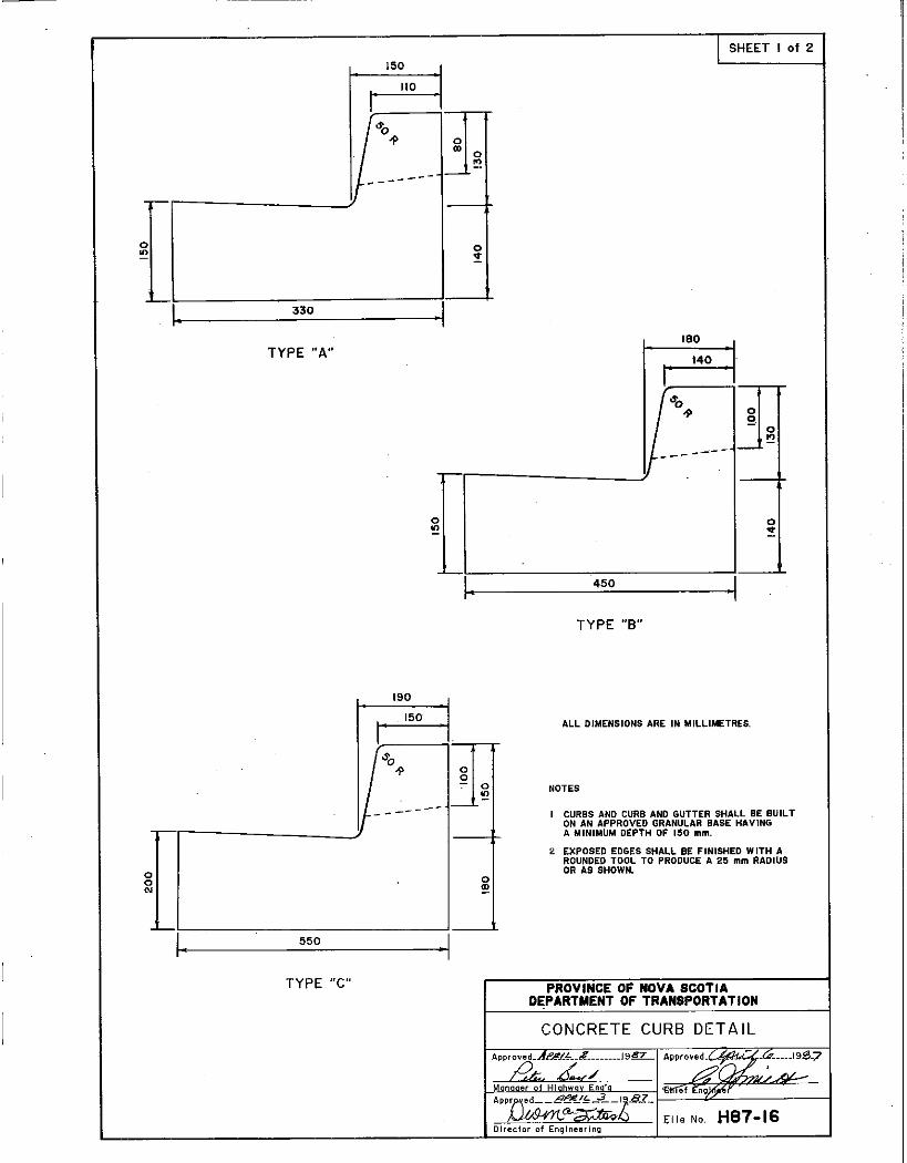
5.7 Curbing. Portland cement concrete curbs shall conform to Division 5, Section 16 of the Standard Specifications, or as approved by the Engineer. Curbing must be placed just prior to the spread of asphalt. The quantity per cubic metre of all ingredients in the concrete shall be forwarded to the Engineer prior to the start of curbing. At least one set (3) of concrete test cylinders (150mm x 300mm) shall be taken for every 100m (linear) of curbing and tested for compressive strength at 7 days (1) and 28 days (2). These results will be forwarded to the Engineer.
NOTE: FOR VARIATIONS AND LISTING PROCEDURES SEE DIVISIONS 7 & 8

PAGE 15 DIVISION 6
PAVING CONSTRUCTION SPECIFICATIONS FOR ROADS SERVICED WITH AN UNDERGROUND STORM SEWER SYSTEM
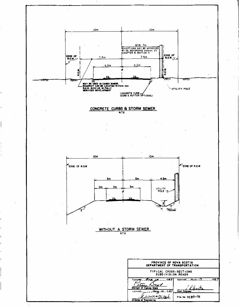
6.1 Roadbed. (1) The roadbed will have a top width of 10m after gravel has been applied. On sections where guard rail is required the roadbed width will be increased by 1m on the side the guard rail is to be installed. The roadbed will be constructed concentric to the centre line of the right-of-way except in areas where extra roadway width is required or extra right-of-way may be required, and will be graded to the satisfaction of the Department. (see attached plate #H87-71) •
(2) The crown of the roadbed shall be at least 150mm.
(3) Black muck, peat and other unsuitable materials under the roadbed must be removed prior to placing embankment material. Rock cuts will be excavated to at least 300mm below the subgrade and backfilled with fill material satisfactory to the Department. Water pockets will not be left in the bottom of rock cuts. All material in cuts or embankment must be approved by the Department. The top 300mm of subgrade must be free of rocks larger than 150mm maximum dimension.
( 4 ) The subgrade and any trenching for services must be well drained and compacted as per Division 2, Sections 8 and 9 of the Standard Specifications. The results of the laboratory and field density tests shall be submitted to the Engineer. At least one field density test shall be taken for every 150m of roadway.
NOTE: THE QUANTITIES SHOWN IN THE SECTIONS, 6.2, 6.3 & 6.6 ARE THE MINIMUM ONLY, AND ADDITIONAL MATERIAL MAY BE REQUIRED TO GIVE SATISFACTORY RESULTS AND TO MEET OVERALL DESIGN CRITERIA.
6.2 Base Course. Base course shall conform to Gravel Class E, Division 3, Section 2 of the Standard Specifications. The base course must be applied to a minimum thickness of 150mm. The results of laboratory and field density tests shall be submitted to the Engineer. At least one field density test shall be taken for every 150m of roadway.
6.3 Surfacing. The surfacing shall conform to Gravel Class A, Division 3, Section 6 of the Standard Specifications. Surfacing must be applied to a minimum thickness of 100mm. The results of laboratory and field density tests shall be submitted to the Engineer. At least one field density test shall be taken for every 150m of roadway.
PAGE 16
6.4 Prime Coat. Prior to the laying of asphalt concrete, when directed by the Engineer, liquid asphalt shall be applied upon the prepared subgrade as per Division 4, Section 5 of the Standard Specifications.
6.5 Tack Coat. Prior to the laying of asphalt concrete upon an existing asphalt directed by the Engineer, tack coat will be applied as per Division 4, Section 1 of the Standard Specifications.
6.6 Paving. Asphalt concrete shall conform to Type C Asphalt Concrete Division 4, Section 4 of the Standard Specifications. The asphalt concrete shall be placed to a total spread of 190 k~/m2 and must be placed in two spreads. The first spread to 110 kg/m of Type B or C and the second spread of 80 kg/m2 of Type C.
Prior to the paving, the developer will provide the Department with an affidavit signed by a Professional Engineer which states that the aggregate(s) and asphalt cement have been duly sampled and tested, and that the asphalt concrete to be manufactured form these ingredients has been duly designed to achieve the specified properties. The affidavit will also list the test results for this testing and design. The Department may also require the affidavit to state that the hot mix asphalt concrete plant conforms to the Standard Specifications.
6.7 Insoection. In addition to the above, a minimum of one series of tests per day shall be performed for each SOOt, of asphalt concrete. Every individual road shall have a least one series of tests.
The series of tests shall include all of the following:
1. Marshall Stability, kN 2. Marshall Flow, x 0.2Smm 3. Air Voids, % 4. VMA, % 5. Asphalt Cement Content, % 6. Gradation of Extracted Aggregate
There shall be at least one field density test per day for each SOOt of asphalt concrete placed. Each lift for every individual road shall have at least one field density test taken.
All test results shall be recorded and forwarded to the Engineer.
6.8 Curbing. Portland Cement concrete curbs shall conform to Division 5, Section 16 of the Standard Specifications or as approved by the Engineer. Curbing must be placed just prior to the first spread of asphaJ, t. The quantity per cubic metre of all ingredients in the concrete shall be forwarded to the Engineer prior to the start of curbing.

PAGE 17
At least one set (3) ·of concrete test cylinders (lS0nun x 300nun) shall be taken for every 100m Clinear) of curbing and tested for their,compressive strength at 7 days (1) and 28 days (2). These results will be forwarded to-·the Engineer.
6.9 Storm Sewers. All underground storm sewer systems will be provided and placed by the sub-divider.

PAGE 18
DIVISION 7
VARIATIONS
7.1 Variations to these specifications may be considered by the Department in cases such as in the Comprehensive Development District (C.O.D.) and these variations would be for the particular C.D.D. for which the variations were neqotiated.
7.2 All Roads in Industrial Parks, Commercial Subdivisions, and Commercial Developments must be paved to all year standards or greater prior to listing by Department of Transportation and Communications. The specifications of this book will apply with the following change:
7.3
(a) Base course material must be applied to give a depth of 3BOmm or greater
(b) Surfacing course material must have a depth of lOOmm or greater.
(c) Asphalt concrete shall be placed to a total spread of 320kg/m2 or greater.
(d) Where curbs are used only Portland Cement Concrete will be acceptable.
All roads on other Provincial Department lands including roads on Native Reserves must specifications and be paved prior to listing Transportation and Communications.
and Federal lands conform to these by Department of

DIVISION 8
LISTING PROCEDURES
PAGE 19
8.1 Before the constructed roads are accepted for listing, the Department must receive confirmation from the Nova Scotia Department of the Environment that all their requirements have been met. In~ addition a certification may be required from a Professional' Engineer confirming the roads and drainage systems within the subdivision have been constructed in accordance with the approved plans and these specifications.
8.2 Listing procedures. When the preceding specifications have been satisfactorily adhered to, the developer may then officially request the Department take over the road system in the subdivision. The request should be accompanied by 6 copies of a final plan showing the entire subdivision, its boundaries, road and drainage layout. The developer will also have a deed prepared deeding all rights-ofway to the Department. At this time the Department may require as built plans and profiles. The Engineer then may recommend the Minister officially list the roads in the subdivision.
APPROVED BY:
• • • • • • • • • • • 1.Y:r.4-':-/. .;2 .'f.-. /J.~ 'j, ... ...... ?I!~ .......... . Dated
........... {~lfi.~a± .J.crs.<i ..... Dated
Deputy Minister
• ~n t ...... ~ • • ~It ••• ~ •• Minister
I

" 'if< .. ..y 48°39'
RAD. 14
~~ ,
FACE OF CURS
!!!
~I i 5.5 I 4.5. I '.0 I
-l 3.0
I I ,.
20
/ MAY. USED IN CAIb WME. ---... ROADW ... y CAN • LOCATED .."... I5fIt litO, •. SUCH .. IN FULL' SEIWIC!D D£V!LON!NT.
'.5
'\ EDGE OF ~OW I
4E1·39'
..1:.L
FACE OF CURB
<'
•
5.5
0.5
~I i ~.5 J ~.s 5.5
I 3.0 ' 3.0 I
r I
.0 I 20 -,
~IIOYINC! OF NOVA SCOTIA DEPARTII!IIT OF TRANSPORTATION
CULS- DE - SAC ~C! ______ 19ftl APf'ROVEO_..AlJ1it!.La ______ 191
,jJ1f.~-I~ 19111 CIIfet II APP~~
Flit No. 1181-12. -"'"11

I 3.,0 I 3.,0 I
"~ I· • __ DJRECT.l0N OF TRAFFIC
~ ALL POSTS 200 " 200" 2J0:=l
0 0
t1~ ~ TI
NOTE:
~LlT ALL BOLTS, NJ'TS ANO WASHERS SHAL\. .~ G~L",1NIZED BY THE HOT DJP PROCESS.
PQSTIOLTS SHALL lI£ CAPABLE OF WITHITANDINCi IOSIIN IN SINGLE SHEAR.
ISmm SQUARE NJTS AND ISfnIn ROUND WASHERS ARt TO IE UI£D. ONE W'A:8H£R
FOR EACH 240", ... " ISm .. eOL T.
-
~
~f----NEUTRAL AXIS
:;:ICii
HEAD
@. W
83 19 )< 64 SLOT FOR POST CONNECTION I 310 _
TYPICAL SECTION OF BEAM
~~~ ~T ~~
SPLICE BOLT DETAil
2.8mm STEEL
"'
*=-AS::::r~ 240 " 16 SOL 1_ 75mm TI1REAO
600
I
'--
I 7~0 I {i 316 ;?
o o ~
'4m
H-f:8-DETAIL OF TERMINAL SECTION
31.
5~~~0 i"" I Q 1
CI ~ _"" I ¢
0::;- C I cl
SPLICE DETAIL
PROVINCE DEPARTMENT
OF NOVA SCOTIA OF TRANSPORTATION
STEEL GUARDRA IL DETA IL
191.Z. Approved .:z?w f" 19~5
AlL:-=
"I. N,. H 87-66
way En-'
AP~;:;;;;;:-CrrreTEn9i~
Director of Engineering
----------------------- .•...... -.-~

POST OFFSET TABLE
FILL OR CUT
X Y
3.BI 0.04
7.62 0·115
11".42 0.34
115.22 0.60
19."M 0 .....
22.S1 1.35
NOTES
RAOIU$= 194.04
, -n 0 n ,,~ g 9 R 9 Q rJ~:if ::.~ ... :-:-::-:::::-~::-:::-:-::.!T~A~N~G~EN~T~=-=-::-:::-:::-:-=:::-~U~: ~--=---.J~~Y_____ - - - - - - - ~~ _EDGE OF SHLO.
CIl_ X - - --
~: 1c::-::-:-::-==-::-:~2~2~ .• ~,:-:-:::::--=~-----------~ _ _ _ _ __ ~ __ E..QG! OF PAVT.
PLAN-FILL OR CUT
4 STANDARD BEAM ELEMENTS
I I - ~ if, ~ ~ // 7/ > '" r7'7'",;z;:r-""".:;r'77777
c::;:;
========t~~':p J~ y,,77/777~7777777J i: :: ~ U ", -.- /77 777777 . 0 77) /// r);J?7r /7/./ / / )77))7 ))
ELEVATION
ALL DIMENSIONS ARE IN METRES.
I. ALL LATERAL DEMENSIONS MEASURED FROM FACE OF RAIL.
2. GUIDE RAIL MAY BE PLACED AS PRACTICABLE FROM EDGE OF SHOULDER. IN NO ,CASE MAY GUIDE RAIL BE PLACED DOWN THE SLOPE.
3. TI1IS DRAWING TO BE USED' IN' CONJUNCTION WITH DWG. FILE No. H87~GG
PROVINCE OF NOVA SCOTIA DEPARTMENT OF TRANSPORTATION
STEEL BEAM GUIDE RAIL INSTALLATION DETAIL SINGLE RAIL END TREATMENT
&:,'--Z/P..··:·'9fl.. , ,/
Monoger of Hi hwoy.£ng'g
A ••• t.t 19.8'::: '~.
Director of EriOlnieeril!9
Approved __ CitLtT~"C._6'T_ 19J1.t_
"£4 //-.«Ou.,~- '0 Chief~ File No. 79 .... (3.5-/8
I
.J
l
10m iOm
MIN.7m I I EXCEPTIONS MAY BE APPROVED
1 IBY cE, REFERENCE MANUAL 23
1 (CHAPTER '0 SECTION 71
E ... OF I 7.5m EDGE OF
7.5m •. o .•. z.., 71/ I .1
4.Sm 4.5m I. "I
, i I" Cl : Cl
"'I ...ll. ....u. '"
"~'''Lty IE ...... I. CAlC' w.... I Z. '('''-'' ,,,,,,,
ROAftAY CAN • LOCATIO WITH,ltI IIIn ''--UTILITY POLE U ••. IUCH A' IN nA.l Y
."YlelD DlYll!WIIINT CONCREtE CURl (CURB' GUTTIER OPTIONAL!
CONCRETE CURBS 8 STORM SEWER N.T.S.
10m 10m
~EDG£ OF ,to.W f-:£DGI. OF ".O.W 0
5m 5m 4,5m
2m 3m 3m UT1LITY~ , POLE
...ll. i --',
V ~T ..do'" 11/ .. _ -' --! ;7,o",,,,
WITHOUT A STORM SEWER N.T.S.
PROVINCE OF NOVA SCOTIA DEPARTMENT OF TRANSPORTATION
TYPICAL CROSS.SECTIONS SUBDIVISION ROADS
A,V'--"'X---- '9U ApprovtL_A...r.G:: ,-l~ ______ 19i1.7
IJ!;; ....,/ /"6 ' M.", of Hi ' ,,{, ,J;;. :.pprcv~~~Q.._ 9-B..l Chi,f Ell . ,
L-~ Fill ND. H e,? .. 7. iSir,cler 01 E i_I
SHEET I of 2
150
110
o ., 0
'" If _-------1-.-,-------____ -3 __ +
o "'
o o '"
330
TYPE "A"
550
TYPE "c"
190
150
o "'
·1
o !
I·
o .,
180
140
450
TYPE "8"
ALL DIMENSIONS ARE IN MILLIMETRES.
NOTES
o v
I CURBS AND CURB AND GUTTER SHALL BE BUILT ON AN APPROVED GRANULAR BASE HAVING A MINIMUM DEPTH OF 150 mm.
2 EXPOSED EDGES SHALL BE FINISHED WITH A ROUNDED TOOL TO PRODUCE A 25 mm RADIUS OR AS SHOWN.
PROVINCE OF NOVA SCOTIA DEPARTMENT OF TRANSPORTATION
CONCRETE CURB DETAIL
ApprovEld._.At".RL.f __ A" ________ J9~ Approved. ~ :.& _____ 19.13.7
& .6 •. '-/ d(]L . AL.-Mona er of HI hwCl' <GtfIef En9)f,rr ApprFled-:::_~PIt!IL..3 ,1,...8.1'-
~a-~t:; F.II' No. H87-16 Director of Engineering
II
I I.
1

o o '" on
210
o o
-'- '------ - - - ---1-'-
285
TYPE "D"
ALL DIMENSIONS -ARE IN MILLIMEiRES.
250
TYPE "F"
.1
o o ..
o on
'"
I SHEET 2 of 2
1~ __ 1_50'--_-l125 _
o o '" on
-'-
NOTES
-------- -
250
TYPE "E"
o o
o o ...
I CURBS AND CURB AND GUTTER SHALL BE BUILT ON AN APPROVED GRANULAR BASE HAVING A MINIMUM DEPTH OF 150 mm.
2 EXPOSED EDGES SHALL BE FINISHED WITH A ROUNDED TOOL TO PRODUCE A 25 mm RADIUS OR AS SHOWN.
PROVINCE OF NOVA SCOTIA DEPARTMENT OF TRANSPORTATION
CONCRETE CURB DETAIL
Ap pr oved • ..A.e&tl. •. F... ___ .l S~?:..
B,z 4/ Monogo.[ of Highw y Eng 9
APprOY~
Director of Eng:!neerlnQ FIle No. H87-16

·
Frome, Grating and Curb Section-IMP -S3610 or Equal
." ... ~~ Norm~G=r2 ~t Road Grade
". ",' 200
-1-
... 1 E 162 ~
" " ' . · . .. 900 m Precast ... 0 . . Concrete '.'
" . ~ .' , . Normal Grad.-. , .' " Catchbasln J" '"1 ':. : A · .' ~ ~
'.' · ,
~ 0
.. :' ~
· , ! ~ 0 ~
.' 0 .. Q · . 0 , , E " 0 ~ Lateral Pipe " ~
to MonhOlo
7 "
~ 0
'. ,
~ ~ , .c:! .... , ,_ ... , , .-· . 00 -"5
I c.
0 • • -0 .................. ., Nc
250 concreteJ
· .. !!! 600 •• · . · , 0 Al . '. ',' 0
~ o~
Pipe ASTM.. " • -J! , ' ~ ~o CI4 Cl. 3 or
" 0 .!;U
300 Concr.'. ., 0 .. -0 Pipe, ASTM on
Q ~-.... ~ . C76 CL.III .' " ~
/ ~ .. _0
" 0 .-, ' z 0" A .. , 1!':
, .. 0 ,,0
, ' . : .:: .. : '. :'OQ .. , . 0 05 . , .. 150 Crushed Stone
~ ~ u
SECTION c 0
PLAN 0 N.T.S.
N:T.S.
Cji Road Grade Top of Curb af
l Depressed SO Guttor Gratln'
7 Height Normal Curb ~
Lin r--/,", ni 'q I.
600 600
ELEVATION - CURB AT CATCHBASIN N.T.S.
PRO V INeE OF NOVA SCOT! A DEPARTMENT OF TRANSPORTATION
TYPICAL 900' mm CATCHBASIN
I AZ2~ED 5t;.2 Bl
APPROVED 19
- ManoQer Of HIQhw"y Eng'Q Ch I al Ena I neer
"PI'R<r1~D ~ 10 19,81 ~
Director of EnljJlnee[lng File No, H 81-73

2.8 Due to maintenance problems:
1. CUl-de-sacs are not to be used when the 1 and can be effectively serviced by other road layouts. All permanent dead end streets, including streets which end at property lines must end in a cul-de-sac (plate H87-72) and be built as per specifications. The grade of the. bulb of a permanent cul-de-sac shall not exceed 4%.
In cases where the road ends within a property and there are plans to extend the road at a future date, the engineer may accept a temporary turning area. Following are guidelines to be used when dealing with temporary turn around areas:
(a) Developers should be encouraged to develop their subdivision in such a manner as to permit deeded intersections to be used as a temporary turning area. The attached plan noted Fig. 1 illustrates this method.
(b) If an intersection can not be used then additional property must be obtained by deed with a min. size of 15 m x 10 m as shown in Figure 2. Due to specific topographical or other conditions a larger area may be required.
In rural areas the turning area must be constructed to the same standard as the road.
In urban areas where specifications require asphalt paving and curb, the turning area will be gravelled as per rural specifications. The normal curb along the frontage of the turning area will be deleted' and a bond will be required to guarantee (a) the restoration of the roadway when the road is extended or (b) to pave and curb the temporary turning area if the road is not extended within a period of three years from date of listing.
2. Boulevards will not be permitted in residential subdivisions.

.... . " ...
TEMPORARY TURNING AREAS
WIO:::W :::::lW 1-0::: :::::llLLUl
----~------------,-
FUTURE STREET
FUTURE STREET
FIGURE 1
------------~-
U END OF LISTING OR PROPERTY
LINE
FIGURE 2
15 m
10m
FUTURE STREET
,----_-L ___ _