subdivision development procedures ......subdivision development procedures, standards and...
TRANSCRIPT

SUBDIVISION
DEVELOPMENT
PROCEDURES, STANDARDS
AND SPECIFICATIONS Adopted by the Macomb County Department of Roads this 17th day of May, 2007 RReevviisseedd:: 55//1177//0077,, 44//1177//0088,, 11//2222//0099,, 22//2233//1100,, 44//1144//1100,, 55//22//1111,, 1122//0055//1122,,
0011//1144//22001166,, 0099//2299//22001177,, 0044//1122//1188

1
TABLE OF CONTENTS PART I – PROCEDURES 6
LAND DIVISION ACT 7 Act 288 of 1967, As Amended 7
DEFINITIONS 7 Office of the County Executive 7 Macomb County Department of Roads (MCDoR) 7 Office of the Macomb County Public Works Commissioner (OMCPWC) 8 Michigan Department of Transportation (MDOT) 8 Permit 8 Roads 8 Variance 8 Tentative Preliminary Plat, Final Preliminary Plat and Final Plat 8 GENERAL REQUIREMENTS 9 Tentative Preliminary Plat 9 Final Preliminary Plat 9 Final Plat 9 ENGINEERING PLANS 10 Plan Submittals 10 Final Plat Approval 10 APPEAL PROCEDURE/VARIANCE REQUEST 11 PART II – STANDARDS AND SPECIFICATIONS 12
SUBDIVISION CONTROL ACT 13 ROAD RIGHT-OF-WAY 13 RIGHT-OF-WAY REQUIREMENTS 14 ROAD LAYOUT AND TRAFFIC SAFETY 14 General 14 Intersection Criteria 15 Construction Signing 15 DRAINAGE REQUIREMENTS 16 General 16 Drainage Easements 16 Retention/Detention Basins & Pump Stations 16
STORM DRAINAGE SYSTEMS 16 Storm Sewer and Underdrain 16 Cross Road Culverts 18 Manholes and Catch Basins 18 Sump Pump Discharge 19 Drainage to Existing County Roads 19 National Pollutant Discharge Elimination System (NPDES) Phase II Requirements for Proposed Subdivisions 19 ROAD DESIGN AND CONSTRUCTION REQUIREMENTS 23 Alignment 23

2
TABLE OF CONTENTS (CONTINUED) Grades 23 Road Cross-Sections 23 Residential Streets 23 Industrial Streets 24 Collector Roads 24 Pavement Section(s) 24 Widening Lane 24 Paved Residential Drive Approaches 24
CONSTRUCTION OF ROADS 25 GRADING 26
Clearing, Grubbing, and Tree Removal 26 Subgrade/Claygrade Preparation 26
AGGREGATE BASE/SUBBASE MATERIAL AND CONSTRUCTION 26 Materials 26
Construction 26 PAVEMENT TYPES 27
BITUMINOUS PAVEMENT 27 Bituminous Base Courses 27 Bituminous Wearing and Leveling Courses 27 General 28 Construction 28 CONCRETE PAVEMENT 28 Materials 28 Lane Tie Bars 29 Special Provision for Concrete Pavements 29 Curb End Transitions 29 Construction 29 Supplemental Pavement Specifications 30 Concrete Curb and Gutter 31 Other Materials and Construction Methods 31
UTILITIES AND SOIL EROSION 31 Sanitary Sewer and Watermain 31 Private Utilities 31 Utility Coordination and Safety 32 Existing Catch Basin/Manhole Structure Covers 32 Erosion Control Provisions 32 Maintenance of Roads during Construction 32 TRAFFIC CONTROL PROVISIONS 32
APPROVAL OF STREETS AND STORM SEWER UNDER MCDOR JURISDICTION 32
TWO YEAR MAINTENANCE INSPECTION BY MCDOR 33

3
TABLE OF CONTENTS (CONTINUED) FINAL ACCEPTANCE OF STREETS AND STORM SEWER UNDER MCDOR JURISDICTION FOR MAINTENANCE BY MCDOR 33 AS-BUILT PLANS 34
PART III – FINANCIAL REQUIREMENTS 35 CERTIFICATE OF INSURANCE 36 FEE AND DEPOSIT REQUIREMENTS 36
Plan Review Fee Deposit 36 Street Signage Fee Deposit 36 Inspection and Administration Fees Deposit 36 Construction Deposit 36
Construction Deposit Coverage 37 Form of Construction Deposit 37 ALL DEPOSIT RELEASE 38

4
APPENDIX A (FIGURES)
Figure 1-1 – Plat and Engineering Plan Approval Flow Chart
Figure 2-1 – Road Geometrics
Figure 2-2 – Stub Road Construction for Temporary Cul-De-Sac and Temporary T-Turnaround
Figure 2-3 – Terminal Butt Joint Detail
Figure 2-4 – Typical Approach and By-Pass Lane Geometrics
Figure 2-5 – Typical Relative Approach Locations
Figure 2-6 – Typical Approach Geometrics
Figure 3-1 – Residential Cul-De-Sac
Figure 3-2 – Industrial Cul-De-Sac
Figure 3-3 – Eyebrow Detail and Joint Location for 28’ B/C to B/C (Residential Subdivisions)
Figure 3-4 – Eyebrow Detail for 36’ B/C to B/C (Industrial Subdivisions)
Figure 3-5 – Vertical Curves for Subdivision Streets
Figure 3-6 – End Transitions
Figure 3-7 – Curb and Gutter Details
Figure 3-8 – Guide for Corner Sight Distance
Figure 4-1 – Typical Cross-Section for 24’ Bituminous Pavement with 2’ Mountable Curb and
Gutter
Figure 4-2 – Typical Cross-Section for 28’ Back-to-Back Concrete Pavement (Residential)
Figure 4-3 – Typical Cross Section for 36’ Back-to-Back Concrete Pavement (Industrial)
Figure 4-4 – Typical Cross Section for 36’ Back-to-Back Concrete Pavement (Collector Roads)
Figure 4-5 – Typical Residential Road Cross-Section for Open Ditch Construction
Figure 4-6 – Typical Subgrade Underdrain for Subdivisions
Figure 4-7 – Pavement Cross-Section Details for Roads and Approaches
Figure 4-8 – Typical Cross-Section Joint Detail
Figure 4-9 – Typical Plan Joint Location for T-Intersections
Figure 4-10 – Typical Plan Joint Location for Industrial and Residential Cul-De-Sacs
Figure 4-11 – 1” Expansion Joint Locations
Figure 4-12 – 2” Expansion Joint Locations for Subdivisions
Figure 4-13 – Standard “Road Ends” Treatments

5
APPENDIX B (FORMS)
Form 1 – Plat Review Checklist
Form 2 – Engineering Plan Review Checklist
Form 3 – Engineer’s and Surveyor’s Certification Letter

6
Part I
PROCEDURES

7
LAND DIVISION ACT ACT 288 OF 1967, AS AMENDED “An Act to regulate the division of land; to promote the public health, safety and general welfare; to further the orderly layout and use of land; to require that the land be suitable for building sites and public improvements and that there be adequate drainage of the land; to provide for proper ingress and egress to lots and parcels; to promote proper surveying and monumenting of land subdivided and conveyed by accurate legal descriptions; to provide for the approvals to be obtained prior to the recording and filing of plats and other land division; to provide for the establishment of special assessment districts and for the imposition of special assessments to defray the cost of the operation and maintenance of retention basins for land within a final plat; to establish the procedure for vacating, correcting and revising plats; to control residential building development within floodplain areas; to provide for reserving easements for utilities in vacated streets and alleys; to provide for the filing of amended plats; to provide for the making of assessors plats; to provide penalties for the violation of the provisions of this act; and to repeal certain parts of this Act on specific dates; and to repeal acts and parts of acts.” This publication is intended to be used as an instrument to expedite the processing of proposed plats, parcel split(s) and property developed by the Condominium Act (Act 59 of 1978) that have public roads planned to be constructed in Macomb County (known as Site Condominiums). The content within pertains to the subdivision of lands located outside of the corporate limits of any township, city or village in the County of Macomb and also pertain to lands within incorporated areas when such lands are adjacent to public roads under the jurisdiction of the Macomb County Department of Roads (MCDOR), County of Macomb, State of Michigan. The contents of this publication do not supersede but are in compliance with Act 288 of 1967, as amended, also known as the Land Division Act and the rules promulgated herein are by authority of Sections 105(c), 183(F) and 248 of said act. If any part of these Subdivision Development Procedures, Standards and Specifications (hereinafter referred to as MCDOR Subdivision Specifications) is found to be invalid, such invalidity shall not affect the remaining portions of this publication which can be given effect without the invalid portion, and to this end the MCDOR Subdivision Specifications are declared to be severable. DEFINITIONS As used herein, the following words shall have the definitions set forth: Office of the County Executive (OCE)
The Office of the County Executive, County of Macomb, State of Michigan. Macomb County Department of Roads (MCDOR)
The Department of Roads, County of Macomb, State of Michigan and/or their duly authorized agents.
8
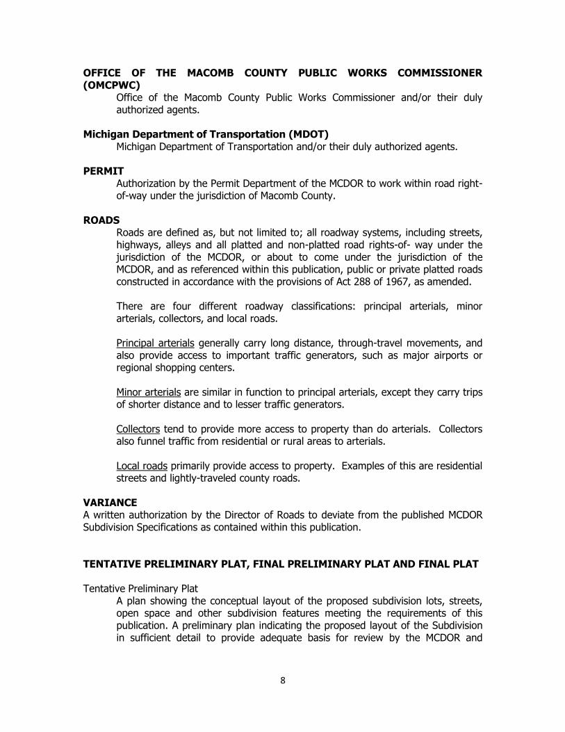
OFFICE OF THE MACOMB COUNTY PUBLIC WORKS COMMISSIONER (OMCPWC)
Office of the Macomb County Public Works Commissioner and/or their duly authorized agents.
Michigan Department of Transportation (MDOT)
Michigan Department of Transportation and/or their duly authorized agents.
PERMIT Authorization by the Permit Department of the MCDOR to work within road right-of-way under the jurisdiction of Macomb County.
ROADS Roads are defined as, but not limited to; all roadway systems, including streets, highways, alleys and all platted and non-platted road rights-of- way under the jurisdiction of the MCDOR, or about to come under the jurisdiction of the MCDOR, and as referenced within this publication, public or private platted roads constructed in accordance with the provisions of Act 288 of 1967, as amended. There are four different roadway classifications: principal arterials, minor arterials, collectors, and local roads. Principal arterials generally carry long distance, through-travel movements, and also provide access to important traffic generators, such as major airports or regional shopping centers. Minor arterials are similar in function to principal arterials, except they carry trips of shorter distance and to lesser traffic generators. Collectors tend to provide more access to property than do arterials. Collectors also funnel traffic from residential or rural areas to arterials. Local roads primarily provide access to property. Examples of this are residential streets and lightly-traveled county roads.
VARIANCE A written authorization by the Director of Roads to deviate from the published MCDOR Subdivision Specifications as contained within this publication.
TENTATIVE PRELIMINARY PLAT, FINAL PRELIMINARY PLAT AND FINAL PLAT Tentative Preliminary Plat
A plan showing the conceptual layout of the proposed subdivision lots, streets, open space and other subdivision features meeting the requirements of this publication. A preliminary plan indicating the proposed layout of the Subdivision in sufficient detail to provide adequate basis for review by the MCDOR and

9
meeting requirements of this publication. This is the 1st step in the platting process.
Final Preliminary Plat
Plans showing a final layout of proposed subdivision features. The final preliminary plat must meet the requirements of this publication and is granted after engineering approval. This is the 2nd step in the platting process.
Final Plat
A final “as-built” construction plan of all or part of a Subdivision prepared and the accuracy certified by a Professional Land Surveyor, in accordance with the requirements of the Land Division Act 288 of 1967, as amended, and suitable for recording at the Macomb County Register of Deeds Office. This is the last step in the platting process and approval is granted after construction of the subdivision is completed.
All other relevant definitions per Act 288 of 1967, as amended, are incorporated herein. GENERAL REQUIREMENTS TENTATIVE PRELIMINARY PLAT
The MCDOR requires that a Tentative Preliminary Plat showing the basic information concerning a proposed development be submitted prior to commencing with land plans and preliminary designs. It is anticipated that such submittals will avoid needless delays and wasted effort by acquainting the Proprietor and their agents with any plans of the MCDOR which may have a bearing on the development and to discuss any points of these MCDOR Subdivision Specifications that may not be clear. See Plat Approval Flow Chart (Appendix A, Figure 1–1).
FINAL PRELIMINARY PLAT
The Final Preliminary Plat shall show all pertinent data necessary to develop Construction Plans and shall be drawn on standard size (24 inch x 36 inch) drawing paper. The proprietor’s engineer or land surveyor will be advised in writing of any approval or rejection within thirty (30) days after receipt of the Final Preliminary Plat. See Plat Review Checklist (Appendix B, Form 1).
FINAL PLAT
1. One copy of the Plat shall be submitted to the MCDOR for review and/or approval.
2. All design considerations shall be in accordance with the MCDOR Subdivision Specifications.
3. The Proprietor’s Engineer or Land Surveyor will be advised in writing of approval or rejection within 15 days after receipt of the Final Plat.
4. Final Plat approval by the MCDOR shall be void after one year from date of approval, unless extended by the MCDOR.

10
ENGINEERING PLANS The Michigan Department of Transportation Standard Plans and Specifications (hereinafter referred to as MDOT Specifications), which includes the current edition of the Michigan Department of Transportation Standard Specifications for Construction are to be adhered to, and are incorporated herein.
Where there is a conflict between the MCDOR Standards and Specifications and that of any other governing agency with respect to road and road drainage improvements, the MCDOR Standards and Specifications shall prevail. The Proprietor’s Engineer will be advised in writing of approval or rejection of the Engineering Plans within 60 days. Absolutely no construction will be authorized until Engineering Plan approval has been granted by the local municipality and the MCDOR, all deposits and fees have paid and a pre-construction meeting has been held. The Engineering Plans shall be of the same dimensions and clarity as the Preliminary Plat (24 inches x 36 inches), shall indicate that all work is to be performed in accordance with the requirements of this publication, and shall show all pertinent design and construction information. See Engineering Plan Review Checklist (Appendix B, Form 2). ALL PLAN SHEETS SHALL INCLUDE THE FOLLOWING MISS DIG INFORMATION: CALL MISS DIG at 811 or 1-800-482-7171 (TOLL FREE) PLAN SUBMITTALS
All Plats and Engineering Plans shall be submitted to the MCDOR Permit and Local Roads Department for review and approval.
FINAL PLAT APPROVAL The Proprietor, having obtained MCDOR approval of the Engineering Plans, shall submit copies of contracts or an engineer’s estimate, for the cost of all roads, utilities and road drainage improvements to be made for the development. The Proprietor will be advised in writing as to the requirements which must be fulfilled, financial and otherwise, to obtain OCE approval of the Final Plat. A Final Plat will not be approved until all required items have been submitted and found acceptable by MCDOR staff. Items which are, or may be required include:
1. MCDOR approval of the Tentative and Final Preliminary Plat. 2. MCDOR approval of the Construction Plans. 3. Application for permit from the MCDOR Permit and Local Roads
Department, if applicable. 4. Financial Deposits
a. Construction Deposit, Inspection and Administration Fees b. Signage Fees c. NPDES Fees
5. Submission of one true copy of the Final Plat along with an original signed and sealed Land Surveyor’s statement stating that the drawings are a true copy of the original Final Plat, a statement that the plat is

11
subject to the approval of each of the officers and agencies, and the date of the certificate.
6. Recorded copies of all offsite easements as required by the MCDOR or Local Municipality.
When all applicable plat procedures and requirements have been fulfilled, the Final Plat will be recommended by the MCDOR’s Director of Roads for approval by the OCE. The final plat will be placed on the next available MCDOR Staff Agenda which shall be within 15 days of receipt, unless otherwise notified. See Plat and Engineering Plan Approval Flowchart for sequence of platting and engineering review submittals (Appendix A, Figure 1-1).
APPEAL PROCEDURE/VARIANCE REQUEST
During the process of developing a new plat, parcel split(s) or site condominium(s), situations may arise which create difficulties in complying with the various requirements of this publication. The Appeal Procedure has been established for requesting a variance from the Director of Roads when the situation requires a change which cannot be granted by MCDOR staff. It should be noted, however, that decisions regarding engineering design or construction standards and specifications will be made by the Director of Roads. The procedure involves:
1. Submission of a letter by the Proprietor or his Engineer to the Director of Roads which shall include:
a. A statement of the situation. b. Reference to the section(s) of these MCDOR Subdivision Specifications for
which the variance is being requested. c. Reasons why the sections cannot be complied with. d. A specific statement of the variance being requested. e. Supporting data from the municipality or other governing agency, when
appropriate. 2. As determined by the Director of Roads, the evaluation and recommendation
may be forwarded to the OCE for its consideration of the request. 3. Written notice of the OCE’s action will be mailed to the Proprietor and other
associated parties. In general, this procedure may take up to 30 days. It is important to note that it is the Proprietor’s obligation to substantiate the position or need. Therefore, care should be taken to insure that all supporting data, documentations, drawings, etc. are included with the letter of request.

12
Part II
STANDARDS AND SPECIFICATIONS

13
SUBDIVISION CONTROL ACT Section 105(c) of the Subdivision Control Act gives County Road Departments the authority to promulgate Rules and Regulations for the construction of roads within newly-created subdivisions. In an effort to assist the Proprietors to this end and to safeguard the future residents of a development, the MCDOR has established the following Rules and Regulations for processing plats within Macomb County. By authority of Act 288 of 1967, as amended, Section 183(1), the MCDOR may require the following as a condition of approval of Final Plat for all highways, streets and alleys in its jurisdiction or to come under its jurisdiction and also for all private roads in unincorporated areas: ROAD RIGHT-OF-WAY Principal Arterial road right-of-way dedication shall be in accordance with the MCDOR Long Range Master Plan (2004-2030). Such dedication will generally be 120 feet for total dedication and 60 feet for half-width dedication. Minor Arterial or Collector road right-of-way dedication shall be in accordance with the MCDOR Long Range Master Plan (2004-2030). Such dedication will generally be 86 feet to 120 feet for total dedication and 43 feet to 60 feet for half-width dedication. Boulevard right-of-way dedication shall not be not less than 86 feet for single-family residential developments and 100 feet for Collector streets and industrial developments. Right-of-way widths greater than those shown on the MCDOR Long Range Master Plan (2004–2030) may be required where the governing body of a Municipality has an adopted and published plan requiring a greater width. Collector street right-of-way dedications shall be a minimum of 70 feet full-width for streets with curbs and gutters and 86 feet full-width for streets with shoulders and open ditches. Industrial street right-of-way dedication shall be a minimum of 70 feet full- width. Dedication of 60 feet width right-of-way with additional 5 feet of public easements for road purposes on each side of the 60 feet right-of-way may be allowed. Cul-de-sac right-of-way dedication shall not be less than 150 feet in diameter in industrial subdivisions. Subdivision street or local road right-of-way dedication shall be a minimum of 60 feet full width in single-family residential subdivisions. Cul-de-sac right-of-way dedication shall be not less than 120 feet in diameter in residential subdivisions. Public roads in multiple housing developments shall have a minimum of 60 feet full width right-of-way. If the MCDOR Traffic Engineer judges that the traffic demands to be placed on the public road meet collector street criteria, the road shall have a minimum of 70 feet full-width right-of-way.

14
RIGHT-OF-WAY REQUIREMENTS [Plats, Parcel Split(s) and Site Condominium(s)]
1. There shall be no half street width dedications other than: a. Additional right-of-way on existing roads and/or undeveloped future
primary and secondary roads, except Subdivision interior roads. b. When the boundary of the proposed plat, parcel split(s) or site
condominium(s) coincides with the boundary of a recorded plat, parcel split(s) or site condominium(s) on which a half of an interior road has previously been dedicated.
2. Dedication of the public roads (roads certified as public and maintained by the MCDOR) within the width limits of the proposed Subdivision shall be minimally as follows:
Section Line Roads 120 feet Quarter Section Line Roads/Collector Roads with Shoulders and Open Ditches 86 feet Industrial Sub Roads/Collector Roads with Curb and Gutters 70 feet Residential Sub Roads/Local Roads 60 feet
a. Dedication of additional right-of-way by deed, road easement and/or drainage easement along section line and/or quarter section line roads that are not within the boundaries of the property being developed may also be required for proper road system improvements.
3. Road right-of-way and drainage easements may be established by the approved and recorded subdivision plat. Right-of-way for frontage roads, interior roads and/or drainage easements not established by a subdivision plat that will be under the MCDOR jurisdiction is governed by a different process. Please contact the MCDOR Right-of-Way Department for further information.
4. Landscaping within the right-of-way shall comply with MCDOR Policy #802 Exhibit A and/or must comply with the MCDOR Long Range Master Plan (2004-2030).
5. The MCDOR prohibits permanent structures to be constructed within the public right-of-way (i.e. subdivision identification signage, retaining walls, fencing, flag poles, berms, etc.).
ROAD LAYOUT AND TRAFFIC SAFETY GENERAL Road geometrics shall provide for internal vehicle circulation between developments as well as to adjacent streets, existing or proposed, public or private (Figure 2-1). Temporary 88 foot diameter Cul-de-sacs are required for street stubs that are 250 feet or greater in length. Dedication of a 15 foot temporary turnaround easement on each side of the proposed 60 foot right-of-way is required (Figure 2-2). Temporary “T” turnarounds (within 60 foot right-of-way) are required for stub streets less than 250 feet in length (Figure 2-2).

15
A Cul-de-sac’s length shall not exceed 800 feet. However, a greater length will be considered if it is approved by the Local Municipality and City/Township Fire Marshal and notice of such approval is furnished to the MCDOR (Figures 3-1 and 3-2). Curbed Islands located within cul-de-sac’s and eyebrows are strictly prohibited. Provide standard “Road Ends” Treatments per the current edition of the Michigan Manual on Uniform Traffic Control Devices (MMUTCD) for roads intended to be extended in the future (Figure 4-13). INTERSECTION CRITERIA It is recommended that all proposed subdivisions have a minimum of two points of ingress/egress (Figure 2-1). It is recommended that bypass lanes be provided at major points of ingress/egress to all proposed Subdivisions. Failure to provide bypass lanes may result in the prohibition of left turn movements to the proposed Subdivision (Figure 2-4). Acceleration and deceleration lanes and tapers are required along all existing section or quarter section line roads with proposed intersections (Figures 2-4 and 2-6). Closely spaced offset intersections are considered to be undesirable for reasons of public safety (Figure 2-5). It is desirable that proposed streets be offset a minimum of 250 feet from an existing street located on the opposite side of an existing road (Figure 2-5). Strip-type subdivisions along existing/proposed primary and local roads where access to each lot is from the major roadway shall be discouraged. The concept of fronting lots on an internal road system is encouraged for reasons of safety. If this cannot be achieved, the proprietor shall be required to construct a minimum 20 foot widening lane with mountable curb and gutter (Figure 3-7) and on each side of roadway along with enclosed drainage facilities along the entire limits of the proposed development outside of the existing primary/local road right-of-way. Township and/or city engineering approval is also required. Minimum corner sight distance for entrances onto existing county roads shall be in accordance with the Posted Speed Limit as designated by the Guide for Corner Sight Distance (Figure 3-8). CONSTRUCTION SIGNING All construction signing shall be provided in accordance with the requirements of the current edition of the MMUTCD. All required signs shall be installed prior to the start of any construction activity along existing streets and all costs incurred shall be borne by the Proprietor and/or Contractor.

16
DRAINAGE REQUIREMENTS GENERAL The Final Plat of a Subdivision, Parcel split(s) or Site Condominium(s) will not be approved by the MCDOR until the Local Municipality and the Office of the Macomb County Public Works Commissioner (OMCPWC) have approved the onsite and offsite drainage systems. Offsite drainage easements, where required, shall be executed in a form acceptable to the MCDOR, Municipality or the OMCPWC, whichever has jurisdiction. Storm drainage systems under MCDOR jurisdiction shall be designed in accordance with the current MCDOR Subdivision Development Procedures, Standards and Specifications. The storm sewer calculations shall include runoff from both the development as well as all offsite contriutary areas. DRAINAGE EASEMENTS It is required that all storm drains conveying road drainage within the plat, parcel split(s) or site condominium(s) boundaries be enclosed, located in properly-sized easements and centered within the middle 1/3 of the easement unless otherwise authorized. The minimum acceptable width of easements for storm sewers shall be: 12 feet wide for sewers 21 inches and under in diameter; 20 feet for sewers 24 inches through 48 inches in diameter; and 30 feet wide for sewers over 48 inches in diameter. Special designs will be considered for major drainage courses. RETENTION/DETENTION BASINS & PUMP STATIONS Retention/detention basins and pump stations shall be designed in accordance with the requirements as set forth by the OMCPWC and/or the appropriate government agency. MCDOR review of these facilities will be with regard to the potential effect on road and road drainage systems, both existing and proposed. The MCDOR will not approve construction plans which include drainage basins and pump stations with the potential of adversely affecting any existing or proposed road and/or road drainage facility. The MCDOR will not accept the responsibility for maintenance of any retention/detention basin or pump station. All such facilities shall be located outside of the MCDOR road right-of-way areas and should outlet to natural drainage areas. It should be noted that road ditches are generally considered unacceptable outlets for retention/detention basins and pump stations. STORM DRAINAGE SYSTEMS
A. STORM SEWER AND UNDERDRAIN 1. Unless otherwise authorized, only 6 inch perforated PVC pipe wrapped in
geotextile fabric shall be used for under drains (Figure 4-6). 2. All current MDOT Standard Specifications, Standard Plans and Requirements
shall be adhered to for the following: a. Materials used in the construction of storm sewer and appurtenant
structures.

17
b. Storm sewer classes based on location and pipe depth. c. Catch basin and manhole design. d. Equipment and construction procedures for the installation of storm
sewers and structures. 3. The main trunk line of the storm sewer system should be located in the right-
of-way 8-feet from the right-of-way line. For curvilinear streets and cul-de-sacs, the MCDOR may require additional manholes in order to locate the main trunk of the storm sewer within practical limits of the outside 8-feet of the right-of-way. Locating storm manholes in the influence of pavement and longitudinal runs of the main trunk line beneath pavement or beneath curbs is not acceptable.
4. For all proposed subdivision (with public roads), the HGL should be at least 1’ (one foot) below the gutter pan.
5. All storm sewer pipes in MCDOR right-of-way and the storm sewer pipes located in easement dedicated to MCDOR that convey right-of-way storm water shall be properly sized according to the system rational flow “Q” that is calculated for a 10-year anticipated storm runoff from the development. The provided capacity (Full Flow) of the storm sewer pipe (based on pipe construction slope) must either be equal to or greater than the system rational flow “Q”.
6. The proposed hydraulic grade line and elevation shall be shown on all storm sewer manholes/catch basins under MCDOR jurisdiction profiles views.
7. The MCDOR requires enclosed storm sewers. All roadway storm sewers must be maintained in the road right-of-way.
8. Design velocities of all enclosed storm sewers shall be such that the velocity will cause neither siltation nor scouring of the pipe (Recommended velocity of 2.5 fps – 7 fps). NOTE: It is understood that certain site specific conditions may result in situations where a design engineer is not able to comply. When this situation arises, the MCDOR will consider each site and the proposed design parameters on their individual merits.
9. All storm sewer pipes shall have a minimum 3.5 feet of cover measured from top of proposed pipe to the top of pavement gutter pan.
10. Wet systems are prohibited. 11. Storm water shall not be carried on the surface for more than 300 feet in one
direction nor more than 600 feet in two directions before entering the catch basin.
12. For accessibility and maintenance reasons, no more than three catch basins shall empty into any one catch basin/manhole. Provide a manhole with catch basin cover and two-foot sump where necessary.
13. No storm sewer will be permitted with a diameter of pipe less than 12 inches. 14. All proposed storm sewer within the proposed right-of-way shall be Reinforced
Concrete Pipe (RCP) C76 Class 4. RCP C76 Class 3 storm sewer is prohibited within the proposed right-of-way.
15. Storm water may be conveyed through road catch basins if storm sewer pipe is 15 inches or less in diameter. However, road catch basins must be offset when the storm sewer pipe is 18 inches or greater in diameter.

18
16. The catch basin under MCDOR jurisdiction receiving surface water shall have 2’ sump at the bottom.
B. CROSS ROAD CULVERTS 1. The minimum size for cross road culverts shall be 12 inches in diameter for
maintenance reasons. 2. The design of cross road culverts shall include flared end sections.
C. MANHOLES AND CATCH BASINS 1. Manholes shall be spaced:
a. A maximum of 300 feet apart on storm sewer lines of 30 inches in diameter or less, and a maximum of 500 feet apart on storm sewer lines larger than 30 inches in diameter.
b. At all changes in the storm sewer’s alignment, grade or size. c. At the junction of sewer.
2. Catch Basins shall be spaced: a. So that the runoff does not exceed the intake capacity of the sewer. b. At all low points in the gutter grade. c. Behind curbs to drain low spots. d. At any location that is apt to have a heavy concentration of runoff.
It is desirable that all catch basins located in the gutter be positioned at lot lines or in the middle of lots to avoid conflict with future driveways. All catch basins shall be tuck pointed and all manholes shall be channeled.
3. Manholes/Catch Basin Covers and Frames
All structures, covers and frames shall be in accordance with designated MDOT Specifications. Covers and frames shall be as follows unless otherwise authorized by the MCDOR. Structure Type Cover and Frame Manhole 4’ Dia. “B” Catch Basin 2’ Dia. or 4’ Dia. “E”, “G” or “K” All manhole and catch basin castings shall have complete bearing on their respective structures and shall be placed so as to insure full accessibility to the structures.
4. Backfilling a. All storm sewer and cross road culverts, along with their related
structures (manholes, catch basins, headwalls and/or end sections), installed in the area between lines projected down from the top of curb or a 1 on 1 slope shall be backfilled with a granular material conforming to MDOT specifications.
b. All the utilities under pavement or within three (3) feet of the edge of the pavement or a 1 on 1 slope shall be backfilled with a granular material conforming to MDOT specifications and Utility Trenches backfill standards. Indicate all compacted sand backfill on plans and profiles.

19
c. In cohesive soils, granular backfilled trenches shall be drained into the storm sewer structures by means of a 6 inch PVC under drain with MDOT 34R open graded aggregate (pea stone) backfill.
d. All granular backfill materials shall be placed in layers not to exceed the capabilities of the mechanical compaction equipment used to achieve the required density of 95% of the material’s maximum unit weight per cubic foot as defined by the Michigan Cone Test.
e. Backfill outside the road influence limits, as defined in Item 3a. above, shall be excavated material. Such backfill shall be placed in 1 foot layers and compacted with an approved mechanical compactor to 95% of the material’s maximum unit weight per cubic foot as defined by AASHTO T99 or the Michigan Cone Test, whichever is applicable.
f. Maintain at least 3.5 feet of cover within roads right-of-way/easements under MCDOR jurisdiction, unless trimming for final subgrade/claygrade.
SUMP PUMP DISCHARGE Open discharge of sump pump flows to the MCDOR right-of-way or storm drainage systems is prohibited for residential subdivisions. All sump leads must be connected into rear yard storm systems and shall meet Township and/or City standards for sump pump discharge. The Proprietor shall not make any subsequent physical modifications after construction approval and MCDOR acceptance of roads as public. DRAINAGE TO EXISTING COUNTY ROADS Any drainage from the proposed development entering the existing county right-of-way storm system, shall be restricted via a 4” PVC pipe restrictor. The maximum velocity shall not exceed 7fps. Drainage from areas which did not previously contribute to the road drainage system will not be accepted unless specifically authorized by the MCDOR. Existing roadside ditches disturbed during construction shall have an established growth of vegetation or other treatment as required by the MCDOR so that the ditches shall be stabilized and free of sedimentation and erosion. NATIONAL POLLUTANT DISCHARGE ELIMINATION SYSTEM (NPDES) PHASE II REQUIREMENTS FOR PROPOSED SUBDIVISIONS The MCDOR is required to fulfill its responsibilities under the National Pollutant Discharge Elimination System (NPDES) Phase II for municipal separated storm sewer systems. In order to facilitate meeting these requirements, the MCDOR will require all Proprietors who will be deeding public and/or private roads and land for public use to submit the following items:
1) A MicroStation® or AutoCAD® accessible electronic file of the as-built plan, including the following in the County road right-of-way:
a. The location and digital photograph of the most downstream discharge point(s) for the storm sewer system (prior to the entrance of the detention/retention basin);

20
b. The location of all storm water storage facilities, including detention/retention ponds and the location of the discharge point (prior to the detention/retention basin); and
c. The location of any innovative storm water management techniques; such as retention/detention ponds, bio-retention trenches, infiltration fields, rain gardens, and porous pavements.
2) A table, in electronic format, including the identification, state plane coordinates, and the public road right-of-way name, detention pond discharge points, and any other discharge points to open or enclosed drains. All data shall be referenced to State Plane Zone 2113 Michigan South Lambert.
All items mentioned above must be submitted prior to final acceptance of the roads.
The following table is the standard procedure to be used for this type of data collection:

21
MACOMB COUNTY DEPARTMENT OF ROADS Illicit Discharge Elimination Program (IDEP)
Attribute Descriptions for Outfall Survey/Drain Investigations
Bold items are suggested to be completed by the Proprietor(s) of new Subdivisions
Attribute
Description of Attribute
Outfall Id Unique outfall identifier (by township and section)
Date Date that the outfall is GPS’d
Time Time that the outfall is GPS’d
Position Lat and Long (degrees, minutes, seconds)
Agency Agency performing survey
MCDOR
MCHD
MCOPW
Init Initials of person operating GPS
Twp Township/City in which the sample point/outfall is located
Jurisd Jurisdiction of discharge point Roads
PWO
Local
State
Private
Photo Digital camera pic# and file path (converted to hotlink in database).
Size (Text) Pipe diameter (inches unless noted otherwise)
Material Pipe Material
PVC
CMP
Iron
Clay Tile
Concrete
Stream/creek
Hidden
Other
BCP
Manhole
Compass Compass direction of a tap within a manhole or catch basin (0°
is North, 90° is east, etc.)
Upstream direction of open ditch or outfall from point sampled
Drawings Subdivision, road or property believed to be drained by discharge point
Flow Flow rate of any dry weather flow None
Slow
Moderate
Fast

22
Attributes
Description of Attribute
Odor Odor of discharge
None
Sewage
Laundry
Gas/Oil
Other
Visual Appearance of discharge Clear
Black
Gray
Muddy
Foamy
Oily
Other
None
E. coli (numeric)
E. coli result (MPN/100 ml)
Detergents (numeric)
Surfactants screening result (ppm)
Conductivity (numeric)
Conductivity screening result (µS/cm)
Temperature (numeric)
Temperature reading (°C)
Comment Field Observations

23
ROAD DESIGN AND CONSTRUCTION REQUIREMENTS ALIGNMENT
1. Eyebrows or bends at street intersections shall be super-elevated per the requirements as set forth by the MCDOR and AASHTO Standards (current edition).
2. Horizontal curves on 28 foot back-to-back roads should be a minimum of 250 radius with a minimum of 50 foot tangent between curves. For 36 foot back-to-back roads, horizontal curves should be at a minimum of 350 foot radius with a minimum 100 foot tangent between curves. Horizontal curves shall be designed in accordance with the MCDOR and AASHTO standards (current edition).
3. Vertical curves shall be designed in accordance with the MCDOR and AASHTO standards (current edition). Vertical curves will be required where the grade change exceeds 2 percent.
4. The centerline of construction shall generally coincide with the right-of-way centerline.
5. The construction plans shall include profiles and cross-sections of existing county roads as deemed necessary to determine that adequate sight distance exists as required by AASHTO standards (current edition).
6. For all proposed roadways to be constructed within a floodplain, the top of road shall be constructed at or above the 100 year floodplain elevation.
GRADES Grades as listed shall apply; however, existing terrain features may warrant a deviation from those listed. Any deviation in grades must be approved by the MCDOR. Subdivision Streets / Industrial Streets Subdivisions Streets/ Industrial Streets and Collector Roads and Collector Roads with with Concrete Curb and Gutter Open Ditches 0.4 % Road Profile Minimum Grade 0.2% 5.0% Road Profile Maximum Grade 5.0% The grades within a street intersection shall not exceed 3 percent for a distance of 100 feet from the point of intersection. ROAD CROSS-SECTIONS
1. Residential Streets a. Standard pavement (28 feet back-to-back)
All roads within a single-family residential development having lot frontage less than 150 lineal feet at the road right-of-way line shall be constructed with a bituminous pavement and concrete curbs and gutters or concrete pavement with integral curbs, as selected by the Proprietor (Figures 4-1 and 4-2).
b. Cul-de-sacs and eyebrows in residential subdivisions For cul-de-sacs and eyebrow geometrics, please refer to Figures 3-1 and 3-3. Islands within the influence of cul-de-sacs and eyebrows are

24
strictly prohibited due to maintenance, safety and EMS accessibility reasons.
c. Large Lot Alternate (24 foot pavement with 3 feet wide aggregate shoulders and ditches on each side of road). All roads within a single-family residential development may be constructed with open ditches and a bituminous or concrete pavement as selected by the Proprietor (Figure 4-5). Cul-de-sacs and approaches to primary or local roads within such developments shall contain a concrete curb and gutter (Figures 3-6 and 3-7).
2. Industrial Streets (36 feet back to back) a. All roads within an industrial development shall be constructed using
concrete pavement with integral concrete curb and gutter (Figure 4-3). b. Cul-de-sacs and eyebrows within Industrial Subdivisions
For cul-de-sacs and eyebrow geometrics, please refer to Figures 3-2 and 3-4. Islands within the influence of cul-de-sacs and eyebrows are strictly prohibited due to maintenance, safety and EMS accessibility reasons.
3. Collector Roads (36 feet back-to-back) Collector roads shall be designed to provide general circulation between developments. These streets shall be designed using concrete pavement with integral concrete curb and gutter (Figure 4-4).
4. Pavement Section(s) See Figures 4-1 through 4-5 for pavement cross-section information.
5. Widening Lane Where a proposed Subdivision abuts with fronting lots on an existing County Road, the Proprietor is required to construct a minimum 20 foot widening lane with integral curb and gutter (Figure 3-7) and enclosed drainage facilities along the entire limits of the frontage. The reason for the widening lane is to maintain through traffic capacity which would be adversely affected by slower moving traffic turning in and out of the driveways. Township and/or City Engineer approval is also required.
6. Paved Residential Drive Approaches a. The construction of a paved residential approach on all primary local road
systems under the authority of the MCDOR shall consist of a minimum thickness of 6 inches of concrete placed on a sand surface of 4 inches minimum or 4 inches of asphalt placed on 6 inches of 21 AA Crushed Aggregate base.
b. Paving block, patterned concrete, and similar decorative approaches will be allowed in the County right-of-way if the property owner agrees to sign the required Hold Harmless Agreement.
c. The maximum width of a paved approach shall be 24 feet with the exception of those with a 3 car attached garage facing the roadway. In those cases, the maximum width shall be 30 feet if the lot size allows for it. In all cases, the width of paved approaches shall not exceed 50 percent of the lot width.
d. For lots in which a horseshoe drive is desirous in addition to the main drive servicing the garage (same side of street), the horseshoe drive cannot exceed 24 feet in width at the existing right-of-way line. This is

25
required for horseshoe drives connecting into main driveways servicing garages.
e. For corner lots in which horseshoe drives are desirous (in addition to a main driveway servicing a garage on the intersecting street), the approach widths (for both driveways) at the existing right-of-way line shall not exceed 12 feet in width. For safety reasons, the minimum offset of the approach nearest the intersection is 40 feet (measured from the road edge or back-of-curb of the intersecting street to the centerline of the proposed approach.)
f. Gravel approaches will not be permitted onto a paved roadway. CONSTRUCTION OF ROADS
1. Road and road drainage improvements shall be started within one year after approval of the Final Plat, Parcel split(s) or Site Condominium(s) unless granted an extension of time by the MCDOR.
2. It is recommended that all proposed public and private underground utilities in the road right-of-way be installed prior to surfacing of the roads.
3. All complaints during the course of construction and prior to acceptance of the roads for maintenance by the MCDOR will be referred to the Proprietor.
4. Inspections: i. Inspections by the MCDOR Permit and Local Roads Department
shall not relieve the Proprietor’s Engineer or the Municipal Engineer of their respective obligations. Spot inspections will be made during various construction stages, such as storm drains, water main, sanitary sewers, finished subgrade, etc. to verify that proper materials and procedures are being used.
ii. The Proprietor’s Registered Professional Engineer/Land Surveyor shall establish the vertical and horizontal alignment within the road right-of-way and drainage easements.
iii. Prior to commencement of any paving operation (aggregate base, curbs, etc.), the grade must be reviewed and approved by a MCDOR representative.
iv. The following inspections of material quality and placement will be made by the MCDOR:
1. 21AA Crushed Aggregate Base 2. Bituminous Paving 3. Concrete Paving 4. Concrete Curb and Gutter
v. A separate permit will be required for installation in MCDOR right-of-way for each of the following:
1. Driveway Approaches, Storm Sewers and Ditching 2. Sanitary Sewer and Watermain 3. Bike Paths and Sidewalks
vi. A minimum of 48 hours notice shall be given to the MCDOR Permits and Local Roads Department prior to the start of each phase of construction.

26
GRADING 1. Clearing, Grubbing and Tree Removal
Stumps, brush, fences and other obstructions within the proposed and existing road right-of-way shall be removed. All trees which are located within 6 feet of the back of curbs or within the centerline of a ditch(es) along proposed Subdivision streets shall be removed for sight distance and other safety concerns as directed by the MCDOR.
2. Prior to start of any utility construction, established rough grade within MCDOR roads right-of-way/easements under MCDOR jurisdiction shall be within +/- 1 foot of the final approved proposed subgrade/claygrade.
3. After backfilling and achieving the required compaction of the storm sewer trench, and from 5 to 10 working days before pavement surfacing or completion of final grade, the Proprietor and/or the representative shall conduct the video inspection and submit a complete set of “as-built plans” and video inspection report of the storm sewer system under MCDOR jurisdiction. Allow enough time for corrective action determined by the video inspection and directed by MCDOR.
4. Subgrade/Claygrade Preparation The finished subgrade shall be free of all topsoil, stumps, organic matter, peat, muck, frost heave material, or any other material that is unstable in nature. During subgrade preparation, the MCDOR will make spot inspections to determine the suitability of the subgrade. Upon completion of subgrade preparation, the subgrade must be proof rolled in the presence of a MCDOR representative for determination of its acceptability prior to aggregate base placement. If unstable ground conditions are encountered within the proposed road influence, the contractor will be directed by the MCDOR representative to undercut to a depth to be determined in the field that will provide a stable subgrade. Verification of the subgrade for vertical and horizontal alignment shall be done by the Proprietor’s Registered Professional Engineer and/or Land Surveyor and reported to the MCDOR representative for final review and approval.
a. Once subgrade is established it must be certified by a Michigan Registered Professional Land Surveyor or Professional Engineer to +/- 1 inch (+/-0.0833 feet). Subgrade cross-sectioning must be provided by the Proprietor’s Engineer/Land Surveyor at 50’ intervals and at all points, high points, PC’s and PT’s of the plan grade shown on the approved engineering plans.
AGGREGATE BASE/SUBBASE MATERIAL AND CONSTRUCTION
A. Materials 1. Aggregate Base construction and materials shall be 21AA crushed
aggregate and in accordance with the current MDOT Specification requirements for 21AA Crushed Aggregate base.
B. CONSTRUCTION This work shall be done in accordance with the current MDOT Specifications except as herein provided.
1. The acceptability of all aggregate base course material will be based on inspection and approval by the MCDOR.

27
2. Layers shall be spread uniformly and graded until the surface is smooth and evenly distributed. The grading and leveling shall be done in combination with rolling by a tamping type, vibrating type, or pneumatic tired roller until each layer is compacted to 95% of its maximum unit weight per cubic foot as defined by the Michigan Cone Test. The compacted base course shall conform to the required line, grade and cross-section shown on the construction plans as approved by the MCDOR.
3. Verification of the sub-base for vertical and horizontal alignment shall be done by the Proprietor’s Registered Professional Engineer and/or Land Surveyor once the subbase is trimmed by the proprietor’s contractor. This data shall be reported to the MCDOR representative for final review and approval. The aggregate base finished surface must be within +/- ½ inch (+/-0.0417 feet) of the grade and cross-section shown on the approved engineering plans. Sub-base cross-sectioning must be provided by the developer’s engineer/surveyor at 50’ intervals and at all low points, high points, PC’s and PT’s.
4. Aggregate base course preparation shall include the removal of wet and unacceptable subgrade material, sub-base or base course material and fine grading. Once the sub-base has been established, the MCDOR requires that it be proof rolled in the presence of a MCDOR representative.
PAVEMENT TYPES
A. BITUMINOUS PAVEMENT This work shall be done in accordance with current MDOT Specifications, except as herein provided:
1. Bituminous Base Courses This work shall be done in accordance with MCDOR standards with particular reference to specifications commonly referred to as HMA 2E3 as modified to current MCDOR specifications. a. The bituminous base course shall consist of mineral aggregate per MDOT
Specifications. b. The bituminous base course shall be placed in approximately equal lifts to
the minimum compacted thickness called for on the approved construction plans.
c. The asphalt cement shall be sampled by an approved testing laboratory and meet a penetration/performance grade per MDOT Specifications or equivalent as directed by the MCDOR.
2. Bituminous Wearing and Leveling Courses
This work shall be done in accordance with MCDOR standards with particular reference to specifications commonly referred to as HMA 5E3 or Low Volume Super-Pave (LVSP) and HMA 4E3 as modified to current MCDOR Specifications. a. Bituminous wearing and leveling courses shall use mineral aggregate as per
MCDOR Standards and Specifications. Recycled Hot Mix Asphalt Mixture:

28
Limits Recycled Asphalt Material (RAP) to maximum of 15 percent binder by weight of the total binder in the mixture. Asphalt shingles and Tires are not allowed.
b. Tier 1 and Tier 2 bituminous pavements are acceptable as set forth by MDOT standards and specifications. Tier 1 and 2 bituminous pavements are subject to the review and approval of the MCDOR Laboratory Testing and Materials representative. Tier 3 bituminous pavements are prohibited.
c. Bituminous wearing and leveling courses shall be placed to the minimum compacted thickness as shown on the approved construction plans.
d. The asphalt cement shall be sampled by an approved testing laboratory and meet a penetration/performance grade per MDOT Specifications or equivalent as directed by the MCDOR.
3. General a. Before succeeding courses of asphalt pavement are placed, the preceding
course shall be swept clean of all dust, dirt or other loose material by the use of a mechanical sweeper or other approved method. The Contractor shall then apply a bond coat of SS-1H to the bituminous surface at the rate of 0.10 gallons per square yard between the 4E3 and the 2E3 layer and at the rate of 0.05 gallons per square yard between the 5E3 or LVSP layer and 4E3 layer (Figure 4-7).
b. The construction of the second and succeeding bituminous courses may have to be delayed, as directed by the MCDOR, until the previously placed bituminous course has sufficiently cooled.
c. Bituminous wearing and leveling courses shall not be placed unless the surface temperature is at least 40º F and rising and bituminous base courses shall not be placed unless the surface temperature is at least 35º F and rising.
d. Terminal Butt joints shall be provided at connections to existing paved roads and at overnight construction joints, when the final course of bituminous surface mixture is being placed. During all other paving operations, joint treatment shall be as directed by the MCDOR (Figure 2-3).
4. Construction a. For proposed drive approaches, acceleration, deceleration, bypass lanes and
tapers abutting existing bituminous roads under the jurisdiction of MCDOR, bituminous or concrete pavement in accordance with MCDOR specifications shall be used (Figure 4-7).
B. CONCRETE PAVEMENT
This work shall be done in accordance with current MDOT Specifications, except as herein provided:
1. Materials The mix design and materials used in producing concrete shall be in accordance with current standards of the MCDOR and MDOT specifications.
a. Joints (refer to Appendix A, Figures 3-3, 3-4, 4-8, 4-9, 4-10, Detail 5-Sheet 1 and Detail 9 – Sheet 2 of MCDOR Standard Detail Sheets)
b. All longitudinal and transverse contraction joints shall be sawed 1/4 inch wide and to a depth of 1/4 of the pavement thickness.

29
c. Transverse pavement joints shall be spaced at 12 foot intervals or as directed for all pavement widths. Transverse joints must be sawed unless otherwise approved by the MCDOR.
d. Longitudinal pavement saw joints shall be provided at third points for 24 and 28 foot wide pavements and at quarter points for 36 foot wide pavements.
e. Prior to sealing, all joints shall be cleaned with a jet of compressed air supplied at a working pressure of not less than 90 psi in addition to any other cleaning which may be required to insure a thoroughly clean joint.
f. Pavement joints shall be filled and sealed with a hot poured rubber-asphalt type compound (1/8 inch below pavement surface) which shall be placed in two applications.
g. 1 inch and 2 inch expansion joints shall be installed throughout the entire subdivision (Figure 4-11 and 4-12).
h. The proposed engineering plans shall be comprised of a separate plan showing all proposed 1” (one inch) and 2” (two inch) expansion joints throughout the entire subdivision. As an alternative, this information can also be shown on the paving plans.
2. Lane Tie Bars Number 5 bars, epoxy coated, 30 inches long, shall be placed along all longitudinal joints, at a right angle to the joint and at 40 inch maximum intervals. Tie bars shall be supported by chairs sufficiently rigid to support the bar during concrete placement (Figure 4-8).
3. Special Provision for Concrete Pavements a. Description. This special provision defines the requirements for the coarse
aggregate to be used in Macomb County Department of Roads concrete paving mixtures.
All provisions of Section 601 of the Michigan Department of Transportation 2012 Standard Specifications Construction shall apply except as stated herein.
b. Materials. Coarse Aggregate 6AA: Section 902. Obtain Coarse aggregate for concrete mixtures from natural aggregate sources. The absorption determined in accordance with ASTM C 127 shall not exceed 2.5 percent.
4. Curb End Transitions Curb end transitions shall be provided as directed by the MCDOR (Figure 3-6).
5. Construction a. For proposed drive approaches, acceleration, deceleration, bypass lanes and
tapers abutting existing concrete roads under the jurisdiction of MCDOR, concrete pavement in accordance with MCDOR specifications shall be used (Figure 4-7).
b. All forms or slip form control line shall be set on a true line and on grade with approximately 1,000 lineal feet set prior to and maintained during paving operations.
c. No concrete shall be produced or placed in rain or threatening weather. When rain appears imminent, the Contractor shall take such precautions as are necessary to protect the concrete from damage.

30
d. All manholes, catch basins and any other utility castings shall be adjusted to line and grade and shall have complete bearing on their respective structures.
e. No concrete shall be placed unless the grade is frost free and the air temperature is at least 25º F and rising, unless specifically approved by the MCDOR. Paving will not be allowed between November 15 and April 15 without written approval from the MCDOR Director of Roads.
f. The Contractor shall provide cold weather protection as needed to protect the concrete from freezing. Any concrete damaged by freezing or frost action shall be removed and replaced at the Contractor’s expense, as directed by the MCDOR representative.
6. Supplemental Pavement Specifications a. Concrete pavement shall be constructed in accordance with the current
MDOT Standard Specifications for Construction. When the Contractor elects to use paving forms, the subgrade, especially that part under the forms, shall be carefully shaped to conform to the pavement grade and thoroughly compacted and cut to grade so that the form when set will be uniformly supported for its entire length at the specified elevation. Forms shall join neatly and in such a manner that the joints are free from play or movement in any direction. Forms shall be set, as herein specified, for at least one day’s construction.
b. The pavement shall be struck-off and consolidated with an approved mechanical finishing machine. The concrete shall be struck-off at such a height that after consolidation and final finishing it shall be at the exact elevation and have the exact crown as shown on plans. A depth of at least two inches of concrete shall be carried in front of the strike-off screed for the full width of the slab. Integral curb shall be formed by extrusion or other approved process to carefully conform to the size and shape shown on the curb and gutter detail (Figure 3-7).
c. The curing of the finished pavement shall be carefully and systematically carried out in accordance with MDOT specifications. Curing compound shall be applied immediately after completion of the finishing operation.
d. Failure to provide sufficient curing material to maintain the protection required or lack of sufficient equipment for care of both curing and other construction requirements shall be cause for the immediate suspension of construction operations.
e. After the forms have been removed, the slab edges shall be cured in the same manner as the slab surface, after which the ground shall be shaped, uniformly graded and compacted in accordance with the requirements as shown on the plans. Care shall be exercised in placing and compacting the earth at the edges of the pavement, so that the new concrete will not be spalled or fractured.
f. Before the pavement will be considered completed in accordance with these specifications and in line for final acceptance, the shoulders, ditches, front and back slopes, and structures shall be placed in a neat and orderly condition conforming to the plans and specifications in all respects. Equipment, surplus material, and construction debris of every description shall be removed from the project.

31
g. The pavement shall be closed to traffic, including the vehicles of the Contractor, for a period of 10 days after the concrete is placed or longer, if in the opinion of the MCDOR representative the conditions make it desirable to extend this time.
h. Following the machine finishing of the pavement surface, it shall be checked and made smooth by scraping or dragging with a rigid straightedge 10 feet in length.
i. Joint sawing shall be carried out and carefully completed as soon as possible after the concrete has attained sufficient set to prevent raveling or spalling caused by the sawing action.
CONCRETE CURB AND GUTTER Concrete curb and gutter or integral curb along all new streets shall be 4 inch mountable curb (Figure 3-7). Concrete curb and gutter construction is subject to the conditions as outlined under the CONCRETE PAVEMENT Section above. OTHER MATERIALS AND CONSTRUCTION METHODS All construction items that are not specified within these Rules and Regulations shall be performed in accordance with the current MDOT Specifications. UTILITIES AND SOIL EROSION SANITARY SEWER AND WATERMAIN All proposed mainline sanitary sewer shall be located in an easement outside of the MCDOR right-of-way. The sanitary sewer must be located at the dimension shown on the City/Township Utility Schedule (per the Codified Ordiance). All proposed mainline watermain is allowed within the MCDOR right-of-way and must be located at the dimension shown on the City/Township Utility Schedule (per the Codified Ordiance). It is required that sanitary sewer and watermain installation be completed prior to placing curb and gutter or any material which is part of the pavement section. These systems must be pressure tested and approved by the appropriate Local Municipality prior to placing concrete or bituminous pavement. All structures constructed with these systems shall be located outside of pavements and curbs. Crossings of these utilities under the pavement shall be at 90º to the pavement unless otherwise approved by the MCDOR. Longitudinal runs of the main trunk line under the pavement are not acceptable. Maintain minimum required cover within roads right-of-way/eastments under MCDOR jurisdiction, unless trimming for final subgrade/claygrade. PRIVATE UTILITIES It is recommended that all private underground utilities (gas, electric, phone, cable, etc.) be installed prior to the surfacing of the road. Such utilities are to be located in the road

32
right-of-way per the local municipalities’ utility schedule. A permit must be obtained from the MCDOR prior to the installation of any utility. UTILITY COORDINATION AND SAFETY The contractor is responsible for contacting MISS DIG at 1-800-482-7171 or 811 at least three (3) working days prior to any site work so that all existing utilities can be identified and marked in the field. EXISTING CATCH BASIN/MANHOLE STRUCTURE COVERS All existing utility structure covers within a paved area shall be adjusted to grade and backfilled with approved material prior to placement of any pavement. EROSION CONTROL PROVISIONS Prior to the start of any construction activity, a soil erosion permit must be obtained from the OMCPWC in accordance with the provisions of Part 91, Soil Erosion and Sedimentation Control of the Natural Resources and Environmental Protection Act, Act 451 of the Public Acts of 1994 (as amended). During all phases of construction, proper soil erosion controls must be installed and maintained by the Contractor and/or Proprietor. Prior to MCDOR acceptance of the streets for maintenance, acceptable vegetation must be established and all temporary soil erosion controls removed from the road right-of-way. MAINTENANCE OF ROADS DURING CONSTRUCTION The Proprietor and/or the contractor is responsible for maintaining proper soil erosion control measures and the sweeping of streets in the existing/proposed MCDOR right-of-way at the end of each workday. If the developer fails to keep the streets free and clear of debris, the MCDOR Maintenance Department will clean the streets and invoice the Proprietor for the services. The proprietor and/or the contractor shall provide winter/summer maintenance during construction. TRAFFIC CONTROL PROVISIONS Proper traffic control measures are required as set forth by the current edition of the Michigan Manual on Uniform Traffic Control Devices (MMUTCD) and per MDOT specifications (for traffic control) during all proposed work within the existing/proposed MCDOR right-of-way. APPROVAL OF STREETS AND STORM SEWERS UNDER MCDOR JURISDICTION:
1. Prior to approval, the Proprietor’s Engineer shall certify that the construction of
all roads, storm sewers, and all other facilities under MCDOR jurisdiction are
substantially in accordance with the vertical and horizontal alignments as shown
on the approved engineering plans. See Engineer’s and Surveyor’s Certification
Letter (Appendix B, Form 3). Please sign the certification letter and provide
original hard copy to MCDOR.
2. All roads within the approved phase(s) of the plat, parcel split(s) or site
condominium(s) must be completed in their entirety prior to approval by the
MCDOR.
33
3. Once the street paving, storm sewer, and all other facilities under MCDOR
jurisdiction have been completed for the entire phase(s) or the entire project per
MCDOR standards and specifications, then the MCDOR will provide on-site
inspection.
4. The on-site inspection will assure MCDOR that all visible construction of roads,
storm sewers, and other facilities under MCDOR jurisdiction have been
completed per the MCDOR standards and specifications, cleaned up, and
acceptable vegetation established.
5. After the approval is granted to the proprietor and/or the contractor’s three year
maintenance (by Proprietor) period will begin for that approved part of the
development under MCDOR jurisdiction.
6. All approved subdivision roads, storm sewers, and other facilities under MCDOR
jurisdiction shall be maintained by the proprietor with no structural
failures/defects for a period of three years after the street paving and storm
sewer had been completed and met MCDOR Standard and Specifications.
7. The Proprietor shall provide winter/summer roads maintenance for the same
three year period.
8. Approval by a MCDOR representative at one construction phase is not a waiver
of any defective or unacceptable condition discovered by the representative at a
later construction phase that may have existed during the prior approval.
9. Approval of any construction phase by the MCDOR does not guarantee
acceptance of the road for maintenance or relieve the Proprietor of
responsibilities or liabilities incurred by the development of the plat, parcel
split(s) or site condominium(s).
TWO YEAR MAINTENANCE INSPECTION BY MCDOR
1. Toward the end of two years of the three year maintenance period, the
Proprietor and/or the Contractor shall schedule on-site inspection to assure that
the proprietor has maintained all streets, storm sewers, and other facilities under
MCDOR Jurisdiction with no structural failures/defects.
2. If the deficiencies are discovered during this on-site inspection then the
proprietor shall correct all the deficiencies to MCDOR’s representative’s
satisfaction
3. Prior to release of part of the construction deposit at the end of two years of the
three year maintenance period, the Proprietor and/or the Contractor shall correct
all the deficiencies.
FINAL ACCEPTANCE OF STREETS AND STORM SEWER UNDER MCDOR
JURISDICTION FOR MAINTENANCE BY MCDOR:
4. Prior to MCDOR’s final acceptance of the roads, the Proprietor’s Engineer shall
submit a complete set of “as-built plans” in accordance with the procedures
outlined in this document.

34
5. Prior to MCDOR’s final acceptance of the roads and storm sewers under MCDOR
jurisdiction, the proprietor shall address any issues related to right-of-
way/easement dedications.
6. Toward the end of proprietor’s three year maintenance period, the MCDOR will
conduct on-site inspection to assure that the proprietor has maintained all
streets, storm sewers, and other facilities under MCDOR Jurisdiction with no
structural failures/defects.
7. If the deficiencies are discovered during this on-site inspection then the
proprietor shall correct all the deficiencies to MCDOR’s representative’s
satisfaction before the final acceptance by MCDOR for maintenance of the roads,
storm sewers, and other facilities under MCDOR Jurisdiction.
8. Final acceptance for maintenance of the roads, storm sewers, and other facilities
under MCDOR Jurisdiction is effective when the final release of all deposit has
been approved and processed by MCDOR.
9. The MCDOR reserves the right to refuse to accept for maintenance any road
which has not been constructed in accordance with the requirements contained
within this publication.
AS-BUILT PLANS
Construction plans showing all approved field changes shall be submitted by the Proprietor’s Engineer to the MCDOR at the completion of construction. These as-built plans are to be submitted on a CD-ROM/USB Flash Drive in PDF format for GIS mapping purposes. The as-built plans shall be in MicroStation® or CAD format. The as-built plans will be kept on file with the MCDOR for permanent public record. As-built plans shall be submitted as follows:
1. Specify vertical datum by reference to the North American Vertical Datum of 1988 (NAVD 88).
2. Reference horizontal datum to the Michigan Coordinate System of 1983 (NAD83-94) Zone: South (NOAA/NGS #2113). Distances drawn in International Feet.
3. Electronic drawing files on removable media (i.e. CD-ROM/USB Flash Drive) in *.dgn format, readable by MicroStation® Version 8.0 or later as manufactured by Bentley Systems, Inc.

35
Part III
FINANCIAL REQUIREMENTS

36
CERTIFICATE OF INSURANCE Prior to the start of construction, the Proprietor and/or the Contractor is required to provide a valid Certificate of Insurance listing the Macomb County Department of Roads as an additional insured. FEE AND DEPOSIT REQUIREMENTS As referenced in the Land Division Act 288 of 1967, “The county road department may adopt as part of the published rules by resolution, a reasonable schedule of fees, to be charged to proprietors seeking approval of plats. The fee shall be for the examination of those plat features which require approval of the county road department as provided in Section 183, and plans and inspection of highways, streets and alleys, together with bridges, culverts, drainage structures or other improvements constructed in connection with the plat and related expenses.” PLAN REVIEW FEE DEPOSIT The industrial and residential subdivisions plan review fee is $175 per acre. For the sites under 20 acres the minimum plan review fee deposit is $3500. The plan review fee shall be posted with MCDOR prior to the start of plan review. Once the site plan approval has been granted the remaining plan review fee deposit will be transferred to the inspection and administration fees deposit. STREET SIGNAGE FEE DEPOSIT
Street signage fees will be determined by the MCDOR and payment shall be made prior to the start of construction. Payment shall be in the form of certified check or cashier check made payable to the “Macomb County Department of Roads.” Signs or appurtenances are the sole responsibility of the proprietor and will not be funded by the MCDOR. Signage fees are non-refundable.
INSPECTION AND ADMINISTRATION FEES DEPOSIT Inspection Deposit and Administration Fees shall be in an amount equal to 6% Paving, 6% Storm Sewer, 4% Watermain, and 4% Sanitary Sewer of the cost for all road and road drainage improvements as determined by the MCDOR. These fees shall be made payable to the “Macomb County Department of Roads” in the form of certified check or cashier’s check prior to any site construction. The MCDOR requires that all Inspection Deposits be issued for a time period of three years commencing on the approximate date that the MCDOR approves the completion of the construction of all roads and storm sewer under MCDOR jurisdiction within the development. These fees shall be posted with MCDOR prior to the start of construction. CONSTRUCTION DEPOSIT Construction Deposits shall be in an amount equal to 10% of the cost of all paving, grading and storm sewer improvements associated with the proposed road(s) within the development. The amount of the Construction Deposit shall be determined by the MCDOR and posted with the MCDOR prior to the start of construction.

37
CONSTRUCTION DEPOSIT COVERAGE Items to be covered by the Construction Deposit shall include but not be limited to; earth excavation, storm sewers, edge drains, culverts, ditches, subgrade/subbase preparation, final pavement, water main, sanitary sewer, erosion control, vegetation establishment and clean-up of the roads and road drainage system, including correction of any erosion damage. FORM OF CONSTRUCTION DEPOSIT The MCDOR requires that all Construction Deposits be issued for a time period of three years commencing on the approximate date that the MCDOR approves the completion of the construction of all roads and storm sewer under MCDOR jurisdiction within the development. The Proprietor shall be held responsible for keeping the expiration date current on the Construction Deposit until all required improvements are completed and the deposit has been released by the MCDOR.
1. Cash Deposits and Certified Checks Cash, Certified Checks and Cashier’s Checks may be used for all Construction Deposits. All checks shall be made payable to the “Macomb County Department of Roads”.
2. Irrevocable Letter of Credit If a developer seeks to utilize an irrevocable letter of credit to assure obligations on the part of the developer to make improvements associated with either a plat, parcel split(s) or site condominium(s) development, an irrevocable bank letter of credit shall be submitted meeting all of the following:
a. The irrevocable letter of credit shall be issued in favor of the Macomb County Department of Roads.
b. The irrevocable letter of credit shall be kept on file with the MCDOR for a period of 2 years and shall provide for notice of expiration by the issuing public bank, at least forty-five (45) days prior to the date of expiration. This notice shall be addressed to the Director of Roads of the MCDOR. (The letter of credit will be drawn upon by the MCDOR if an acceptable replacement is not in place prior to expiration).
c. The issuing public bank must be approved by the MCDOR. The MCDOR requires that the issuing public bank be licensed to do business in the State of Michigan and have an A.M. Best Rating of “A” or better.
d. In the event there has been a change in costs or pricing prior to renewal, the irrevocable letter of credit requirement shall be increased to insure available funds for completion of improvements.
e. Any other funds on deposit with the MCDOR as they relate to the development may be utilized to complete improvements if funds are insufficient or unavailable from the letter of credit.
Prior to MCDOR granting approval of the completion of the roads,
storm sewers, and other facilities under MCDOR jurisdiction, the
proprietor shall extend the expiration date of the letter of credit Two
years beyond the proposed approval date.
38
Prior to MCDOR’s approval of the two years maintenance period, the
proprietor must maintain 50% of the construction deposit until the
street paving, storm sewer, and all other facilities under MCDOR
jurisdiction have been fully accepted.
ALL DEPOSITS RELEASE Once the street paving, storm sewer, and all other facilities under MCDOR jurisdiction
have been completed, have met the MCDOR standards and specifications, and have
been fully accepted by MCDOR, then the final release of all deposits will be processed.

APPENDIX A (Figures)

TENTATIVE PRELIMINARY PLAT
GRANTED APPROVAL BY THE LOCAL MUNICIPALITY
3 COPIES OF FINAL PRELIMINARY
PLAT SUBMITTED TO MCDOR
4 SETS OF ENGINEERING PLANS
SUBMITTED TO MCDOR FOR
REVIEW
TENTATIVE PRELIMINARY PLAT
REVIEW BY MCDOR
MCDOR DISTRIBUTION OF PLAT:
1) MCDOR RECORDS
2) PROPRIETOR’S DESIGN ENGINEER
3) CLERK OF LOCAL MUNICIPALITY
FINAL PLAT SUBMITTED TO
MCDOR FOR APPROVAL AND ENDORSEMENT
CONSTRUCTION OF ROAD AND
ROAD DRAINAGE MAY BEGIN. FEES
MUST BE POSTED WITH MCDOR.
NOTIFICATION OF APPROVAL TO:
1) PROPRIETOR
2) DESIGN ENGINEER 3) CLERK OF LOCAL
MUNICIPALITY 4) MACOMB COUNTY OFFICE OF
PUBLIC WORKS
NOTIFICATION TO:
1) PROPRIETOR
2) PROPRIETOR’S ENGINEER
COPIES OF CONTRACTS AND/OR
ENGINEER’S ESTIMATES FOR
COST OF ROAD AND ROAD DRAINAGE IMPROVEMENTS SUBMITTED TO MCDOR
FINAL PLAT PICKED-UP BY
PROPRIETOR
MCDOR FINAL PLAT APPROVAL
REQUIREMENTS DETERMINED
FINAL PLAT AND ALL ITEMS
REQUIRED FOR FINAL APPROVAL
SUBMITTED TO MCDOR FOR EVALUATION
MCDOR DISTRIBUTION OF
APPROVED PLANS:
1) MCDOR RECORDS (1 SET) 2) MCDOR FIELD PERSONNEL
(2 SETS) 3) PROPRIETOR’S ENGINEER
(1 SET)
MACOMB COUNTY OFFICE OF
PUBLIC WORKS AND DESIGN
ENGINEER NOTIFIED OF APPROVAL OR REJECTION
NOTE: Tentative and Final Preliminary Plat approval will not be granted by MCDOR until Municipal Approval has been
granted. Section designation relative to Act 288 of 1967, as amended, as it applies to the MCDOR.
MACOMB COUNTY DEPARTMENT OF ROADS PLAT AND ENGINEERING PLAN APPROVAL FLOW CHART
Figure 1-1

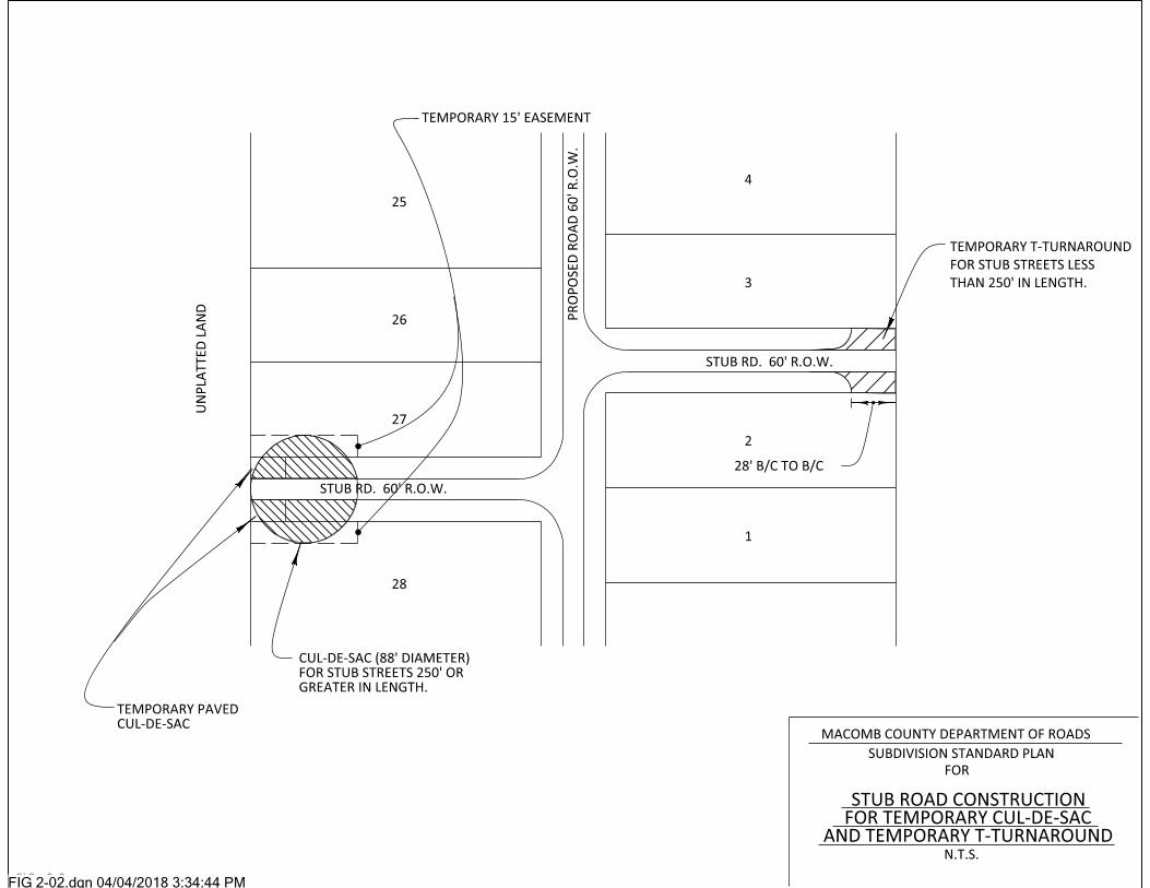
FIG 2-02.dgn 04/04/2018 3:34:44 PM

FIG 2-03.dgn 04/04/2018 3:36:14 PM

FIG 2-04.dgn 04/05/2018 10:41:54 AM

FIG 2-05.dgn 04/05/2018 10:40:05 AM

FIG 2-06.dgn 04/05/2018 10:34:29 AM

FIG 3-01.dgn 04/05/2018 10:43:17 AM

FIG 3-02.dgn 04/05/2018 10:44:44 AM

FIG 3-03.dgn 04/05/2018 10:46:15 AM

FIG 3-04.dgn 04/05/2018 10:47:16 AM

FIG 3-05.dgn 04/05/2018 10:49:47 AM

FIG 3-06.dgn 04/05/2018 10:51:07 AM

FIG 3-07.dgn 04/05/2018 10:53:24 AM

FIG 3-08.dgn 04/05/2018 10:54:50 AM

FIG 4-01.dgn 04/05/2018 10:55:56 AM

FIG 4-02.dgn 04/05/2018 11:01:55 AM

FIG 4-03.dgn 04/05/2018 11:02:51 AM

FIG 4-04.dgn 04/05/2018 11:06:11 AM

FIG 4-05.dgn 04/05/2018 11:06:58 AM

FIG 4-06.dgn 04/05/2018 11:08:02 AM

FIG 4-07.dgn 04/05/2018 11:09:29 AM

FIG 4-08.dgn 04/05/2018 11:10:44 AM

FIG 4-09.dgn 04/05/2018 11:12:03 AM

FIG 4-10.dgn 04/05/2018 11:12:54 AM
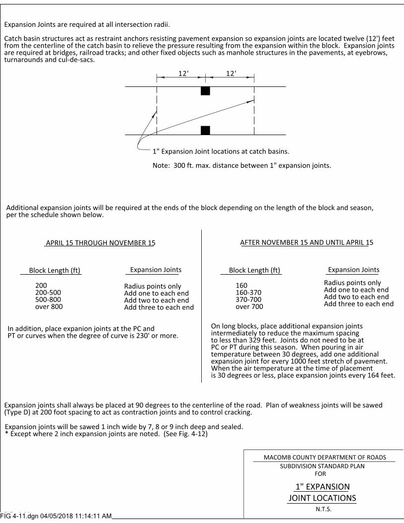
FIG 4-11.dgn 04/05/2018 11:14:11 AM

FIG 4-12.dgn 04/05/2018 11:15:09 AM

FIG 4-13.dgn 04/05/2018 11:16:17 AM

APPENDIX B (Forms)
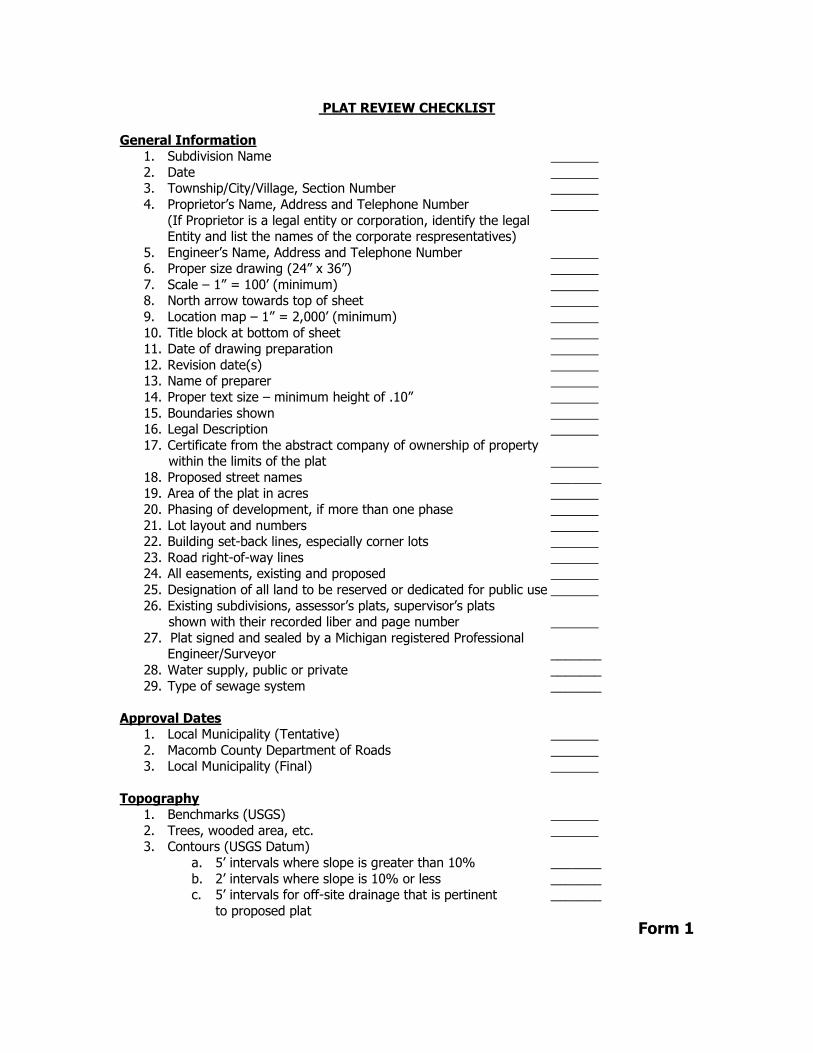
PLAT REVIEW CHECKLIST
General Information 1. Subdivision Name
2. Date 3. Township/City/Village, Section Number
4. Proprietor’s Name, Address and Telephone Number
(If Proprietor is a legal entity or corporation, identify the legal Entity and list the names of the corporate respresentatives)
5. Engineer’s Name, Address and Telephone Number 6. Proper size drawing (24” x 36”)
7. Scale – 1” = 100’ (minimum) 8. North arrow towards top of sheet
9. Location map – 1” = 2,000’ (minimum)
10. Title block at bottom of sheet 11. Date of drawing preparation
12. Revision date(s) 13. Name of preparer
14. Proper text size – minimum height of .10”
15. Boundaries shown 16. Legal Description
17. Certificate from the abstract company of ownership of property within the limits of the plat
18. Proposed street names _______ 19. Area of the plat in acres
20. Phasing of development, if more than one phase
21. Lot layout and numbers 22. Building set-back lines, especially corner lots
23. Road right-of-way lines 24. All easements, existing and proposed
25. Designation of all land to be reserved or dedicated for public use
26. Existing subdivisions, assessor’s plats, supervisor’s plats shown with their recorded liber and page number
27. Plat signed and sealed by a Michigan registered Professional Engineer/Surveyor _______
28. Water supply, public or private _______
29. Type of sewage system _______
Approval Dates 1. Local Municipality (Tentative)
2. Macomb County Department of Roads 3. Local Municipality (Final)
Topography 1. Benchmarks (USGS)
2. Trees, wooded area, etc. 3. Contours (USGS Datum)
a. 5’ intervals where slope is greater than 10% _______
b. 2’ intervals where slope is 10% or less _______ c. 5’ intervals for off-site drainage that is pertinent _______
to proposed plat
Form 1

4. Location of streams, lakes and swamps with directional drainage
arrows and elevations
5. Location, width and names of all platted streets, railroad, military rights-of-way, public areas, permanent buildings or structures
6. Municipal corporation lines within or adjacent to the tract 7. Cemeteries
8. Parks 9. State and Federal Highways
10. Existing Private Roads
11. Wetland areas 12. Electrical transmission lines and towers
13. Gas and oil lines and pump stations 14. Existing water lines and pump stations
15. Existing sanitary sewers and pump stations
16. Radio and Television towers 17. Other pertinent factors
Drainage
1. Location map showing upstream watershed area contributing to the flow into the subdivision
2. Existing drainage course showing culverts, bridges and dams
(private, township, county, other) 3. Mean surface elevation of lakes and streams
4. General drainage plan and outlet within the subdivision 5. Proposed/existing drainage easements on-site and off-site
6. 100-year Flood Plain Limits
7. On-site detention/retention plan, if applicable
Roads 1. Proposed rights-of-way in accordance with MCDOR standards
2. Road alignment data
3. Typical road cross-sections 4. Proposed utility locations in conformance with MCDOR
Standards 5. Layout of streets, alleys and public crosswalks, if any, with
width notes, and cross-sections (Street layout is subject to approval of MCDOR)
6. Sight distance information at entrance to existing main road
7. Connections to existing roads 8. Stubs to plat limits for extension to adjoining undeveloped
areas 9. Treatment of dead end streets with permanent cul-de-sacs
or temporary turnarounds
10. Soil types per Soil Conservation Service Maps
Form 1 (continued)

ENGINEERING PLAN REVIEW CHECKLIST
Date ____________________________________
Subdivision Information
Subdivision Name ________________________________________________________________
Section # __________________________ City/Twp/Village _____________________________
Engineer’s Information Engineer’s Name _________________________________________________________________
Engineer’s Firm __________________________________________________________________ Address ________________________________________________________________________
City _________________________________ State _____________ Zip ___________________
Telephone # ____________________________ Fax # _________________________________
Proprietor’s Information Proprietor’s Name ________________________________________________________________
Address ________________________________________________________________________
City _________________________________ State _____________ Zip ___________________ Telephone # ____________________________ Fax # _________________________________
Note: If the Proprietor is a legal entity or corporation, identify the legal entity and list the names of the corporate representatives.
General Information
1. Cover Sheet (signed and sealed by a Michigan Registered Professional Engineer) ______
2. Typical Cross-Section Quantity Sheet and General Notes ______ 3. Overall Utility Sheet ______
4. Existing Topography Sheet ______ 5. Sanitary Sewer and Watermain Plan and Profile ______
6. Storm Sewer Plan and Profile ______
7. Offsite Drainage Plan and Profile ______ 8. Paving Plan and Profile ______
9. Storm Sewer Drainage Area, Storm Sewer Design Calculations ______ 10. Approach an Intersection Detail Sheet (1” = 20’) ______
11. Grading Plan ______
12. Pavement Details Sheet ______ 13. Drawing on proper sheet size (24” x 36”) ______
14. Plan date/revision date ______ 15. North arrow towards top of sheet ______
16. Permanent B.M. Elevations (USGS Datum) ______ 17. Title block in lower right hand corner of plans ______
18. Contours
a. 5’ intervals where slope is greater than 10% ______ b. 2’ intervals where slope is 10% or less ______
c. 5’ intervals for offsite drainage area ______ 19. Topography ______
20. Street Names ______
21. Lot Layout and Numbering ______ 22. Phasing of Development ______
23. Legal Description of proposed Subdivision ______
Form 2

Drainage
(Note – Storm sewer draining pavements must be located in the road right-of-way)
1. Existing drainage courses and structures ______ 2. Design surface elevation of lakes and streams (including storm sewer outlets) ______
3. Drainage plan layout (show watershed area to each structure, including ______ off-site area entrance points)
4. Retention/Detention Basin along with calculations, if applicable ______ 5. Easements
a. Off-site ______ (width) ______
b. On-site ______ (width) ______ 6. Ditch cross-section(s)
a. Profile minimum grade of 0.20% ______ b. Slope protection ______
7. Culverts size (12” minimum)
a. Inverts _______ ______ 8. MDOT designation of structure covers ______
9. Proper catch basin spacing ______ 10. Proper manhole spacing ______
11. Plan and profile of storm sewers showing watermain crossings, sanitary and other utility clearances (minimum 1.5’ of vertical clearance between utilities) ______
12. Hydraulic gradients of storm sewers shown on profiles ______
13. Clean-out profile of existing off-site drainage ditches ______ 14. Maintenance jurisdiction of off-site drains (Macomb County Public Works,
Township, MCDOR, City, Private or Other) ______ 15. Macomb County Public Works approval of county drain connection ______
16. Compacted sand trench backfill under and within 3’ of pavement ______
17. 6” PVC edge drain along both sides of back of curb (located 1’ from back of curb ______ to centerline of edge drain). Drop inverts 0.1’ at sewer size changes or 90o
turns. Keep hydraulic gradient at least 1’ below the profile’s finish grade. 18. Storm sewer structures (manholes and catch basins) minimum of 4’ diameter ______
19. Sufficient slope to obtain at least 2.5 FPS velocity ______
20. Size, slope, type of pipe, sewer inverts and rim elevations at all storm structures ______ 21. Structure spacing
a. 300’ maximum spacing for catch basins/manholes with pipe diameter of 30” or less ______
b. 500’ maximum spacing for catch basins/manholes with pipe diameter of 36” or greater ______
Paving and Grading 1. Topographic Survey Plan (show existing ground contour lines) ______
2. Off-site elevations (100’ beyond each property line) ______ 3. Pavement cross-sections shown per MCDOR standards ______
4. Curb detail shown per MCDOR standards. Asphalt curbs not allowed. ______
5. Proposed elevations in boxes ______ 6. Maintain 0.30’ min. – 0.50’ max. drop around curb returns at all intersections. ______
7. Show top of curb and gutter elevations ______
Form 2 (continued)

8. Sidewalks
a. Along existing public rights-of-way ______
b. Along both sides of all proposed rights-of-way ______ c. Within a site, as necessary ______
d. Cross-section shown – 4” concrete minimum (8” concrete at drive crossings) ______
9. On-site and off-site pavement quantities (i.e., LF curb, pavement area, ______ sidewalk area, etc.) shown on plan
10. Proposed pavement drainage slopes (longitudinal slopes and cross-slopes) ______
11. Adequate handicap access per ADA standards ______
Roads 1. Proposed right-of-way width ______
2. Road alignment (survey data) horizontal curve data ______
3. Intersection alignment ______ 4. Turnarounds for temporary and permanent cul-de-sac details (1” = 20’) ______
5. Plan and profile elevations and grades (including existing ground elevations) ______ 6. Curb return elevations and radii ______
7. Provide vertical curve data, if grade change exceeds 2% ______ 8. Provide intersection, eyebrow and cul-de-sac details (1” = 20’) (elevations, ______
dimensions and drainage scheme)
9. Cul-de-sacs – maximum length 800’ ______ 10. Provide road profiles for all proposed subdivision roads ______
11. Show centerline curve data ______ 12. Show stationing left to right ______
13. Adequate sight distance ______
14. Soil boring data (400’ maximum spacing and 10’ below proposed grade or existing ground, whichever is deeper, to be shown on plan and profile sheets),
if applicable ______ 15. Deceleration/acceleration lane(s), taper(s), by-pass lane(s) ______
16. Pavement cross-section(s) indicated ______
17. Concrete end headers at end of stub streets ______ 18. Standard “road ends” treatment at end of stub streets ______
19. Steel beam guardrail per MDOT Standards, if applicable ______
Form 2 (continued)

ENGINEER’S and SURVEYOR’S CERTIFICATION LETTER Macomb County Department of Roads 117 South Groesbeck Highway Mt. Clemens, MI 48043 Attention: Permits and Local Roads Department Manager Ladies and Gentlemen: RE: , Section , Township I hereby certify that all roads and road drainage improvements within are complete and within MCDOR allowable tolerances for with the vertical and horizontal alignments as shown on the approved engineering plans and specifications as filed with the Macomb County Department of Roads, and that all monuments related to the road right-of-way as shown on the plat are in place and were in good condition at the time of placement or that proper requirements in accordance with Section 125 of the Subdivision Control Act of 1967 have been provided for. Proprietor’s Engineer/Surveyor Professional Seal of a Michigan Registered Civil Engineer/Land Surveyor
Form 3