transport and main roads specifications mrts206 provision...
TRANSCRIPT
Technical Specification Transport and Main Roads Specifications MRTS206 Provision of Variable Speed Limit and Lane Control Signs July 2017

Transport and Main Roads Specifications, July 2017
Copyright
http://creativecommons.org/licenses/by/3.0/au/
© State of Queensland (Department of Transport and Main Roads) 2017
Feedback: Please send your feedback regarding this document to: [email protected]

Technical Specification, MRTS206 Provision of Variable Speed Limit and Lane Control Signs
Transport and Main Roads Specifications, July 2017 i
Contents
1 Introduction ....................................................................................................................................4
2 Definition of terms .........................................................................................................................4
3 Reference documents ...................................................................................................................5
4 Quality system requirements .......................................................................................................6
4.1 Samples for acceptance ................................................................................................................. 6
5 Functional requirements ...............................................................................................................7
5.1 Scope .............................................................................................................................................. 7
5.2 General ........................................................................................................................................... 7
5.3 Control methods.............................................................................................................................. 8
5.4 Site controller .................................................................................................................................. 8
5.5 Frame display time ......................................................................................................................... 9
5.6 Flashing display control .................................................................................................................. 9
5.7 Communications timeout ................................................................................................................ 9
5.8 Permissible Frame Combinations (PFC) and rules ........................................................................ 9
5.9 Unique hardware identifiers .......................................................................................................... 10
5.10 Configuration management .......................................................................................................... 10
5.11 Sign fault management ................................................................................................................. 10
5.12 Local event logging ....................................................................................................................... 11
5.13 Watchdog ...................................................................................................................................... 11
5.14 Time synchronisation .................................................................................................................... 11
6 Mechanical and physical requirements .................................................................................... 11
6.1 General ......................................................................................................................................... 11
6.2 Sign enclosure .............................................................................................................................. 11 6.2.1 Doors ........................................................................................................................... 12 6.2.2 Front cover .................................................................................................................. 12 6.2.3 Front cover retention method ...................................................................................... 12
6.3 Mounting structure ........................................................................................................................ 12
6.4 Telecommunications field cabinets ............................................................................................... 12
7 Operational requirements of sign displays .............................................................................. 13
7.1 General ......................................................................................................................................... 13
7.2 Display technology ........................................................................................................................ 13
7.3 LED output .................................................................................................................................... 13
7.4 Character formats ......................................................................................................................... 13
7.5 Display changes............................................................................................................................ 14
7.6 Display colour ............................................................................................................................... 14
7.7 Default display .............................................................................................................................. 14
7.8 Red annulus .................................................................................................................................. 15
7.9 Red cross display ......................................................................................................................... 15
Technical Specification, MRTS206 Provision of Variable Speed Limit and Lane Control Signs
Transport and Main Roads Specifications, July 2017 ii
7.10 White arrow displays ..................................................................................................................... 15
7.11 Flashing display elements ............................................................................................................ 16 7.11.1 Flashing partial annulus .............................................................................................. 16
7.12 Bitmap display............................................................................................................................... 16
7.13 Conspicuity devices ...................................................................................................................... 16
7.14 Internal clock ................................................................................................................................. 16
8 Optical performance ................................................................................................................... 16
8.1 Test procedures ............................................................................................................................ 16
8.2 Luminance .................................................................................................................................... 17
8.3 Luminance intensity half angle ..................................................................................................... 17
8.4 Sun phantom................................................................................................................................. 17
9 Site controller control system ................................................................................................... 17
9.1 General ......................................................................................................................................... 17
9.2 Maintenance communications port ............................................................................................... 18
9.3 Control communications ports ...................................................................................................... 19
9.4 Product Host Control System – control/diagnostics software ....................................................... 19
9.5 LED intensity control ..................................................................................................................... 20
9.6 Temperature control ..................................................................................................................... 20
9.7 Communication protocol ............................................................................................................... 20
9.8 Bus arbitration ............................................................................................................................... 20
10 Sign control system ................................................................................................................... 20
10.1 General ......................................................................................................................................... 20
10.2 Sign maintenance communications port ....................................................................................... 21
10.3 Sign control communications port................................................................................................. 21
10.4 LED intensity control ..................................................................................................................... 21
10.5 Temperature control ..................................................................................................................... 21
10.6 Bus arbitration ............................................................................................................................... 21
11 Installation requirements ........................................................................................................... 21
12 Environmental ............................................................................................................................. 22
13 Electrical ...................................................................................................................................... 22
14 ITS network telecommunications.............................................................................................. 22
15 Testing and commissioning ...................................................................................................... 22
15.1 General ......................................................................................................................................... 22
15.2 Factory acceptance tests .............................................................................................................. 22
15.3 Test VSLS and/or VSL/LCS .......................................................................................................... 23
15.4 Configuring frames ....................................................................................................................... 23
16 Documentation ............................................................................................................................ 23
17 Training ........................................................................................................................................ 23
18 Maintenance ................................................................................................................................ 23
Technical Specification, MRTS206 Provision of Variable Speed Limit and Lane Control Signs
Transport and Main Roads Specifications, July 2017 iii
19 Handover ..................................................................................................................................... 23
Appendix A: Allocation of functionality between TMS and site controller ................................... 24
Appendix B: Referenced variables and default settings ................................................................. 29
Appendix C: Full listing of frame designations ................................................................................ 30
Technical Specification, MRTS206 Provision of Variable Speed Limit and Lane Control Signs
Transport and Main Roads Specifications, July 2017 4
1 Introduction
This Technical Specification defines the design, supply, installation, testing and commissioning, performance, documentation, training, maintenance and handover requirements for Variable Speed Limit Signs (VSLS), Variable Speed Limit and Lane Control Signs (VSL/LCS) and associated site controllers.
These signs may be used as:
• part of an overall traffic management system to detect, monitor, manage and control traffic on the road network by altering the posted speed limit and/or lane control status throughout a defined zone, and as
• a standalone device able to be controlled manually during commissioning, maintenance and/or special operating activities.
This Technical Specification shall be read in conjunction with MRTS01 Introduction to Technical Specifications, MRTS50 Specific Quality System Requirements and other Technical Specifications as appropriate.
This Technical Specification forms part of the Transport and Main Roads Specifications Manual.
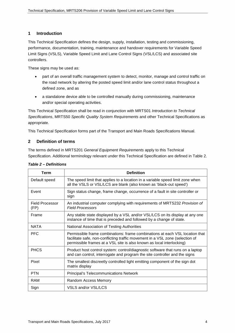
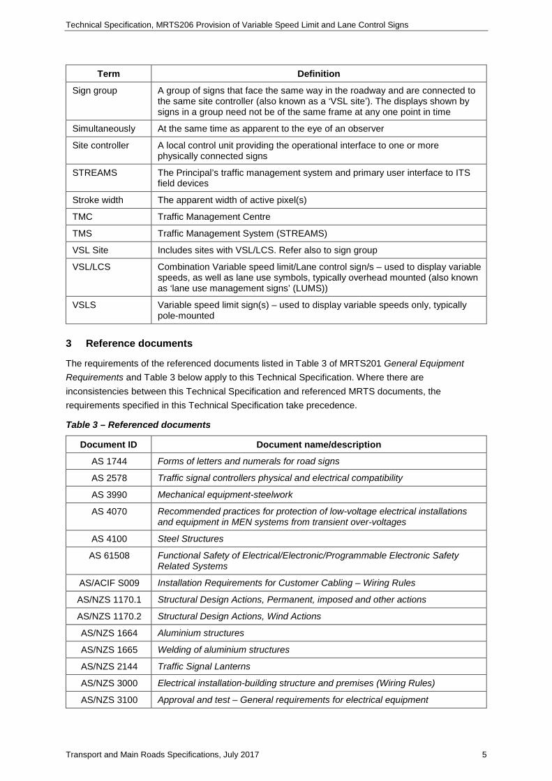
2 Definition of terms
The terms defined in MRTS201 General Equipment Requirements apply to this Technical Specification. Additional terminology relevant under this Technical Specification are defined in Table 2.
Table 2 – Definitions
Term Definition
Default speed The speed limit that applies to a location in a variable speed limit zone when all the VSLS or VSL/LCS are blank (also known as ‘black-out speed’)
Event Sign status change, frame change, occurrence of a fault in site controller or sign
Field Processor (FP)
An industrial computer complying with requirements of MRTS232 Provision of Field Processors
Frame Any stable state displayed by a VSL and/or VSL/LCS on its display at any one instance of time that is preceded and followed by a change of state.
NATA National Association of Testing Authorities
PFC Permissible frame combinations: frame combinations at each VSL location that facilitate safe, non-conflicting traffic movement in a VSL zone (selection of permissible frames at a VSL site is also known as local interlocking)
PHCS Product host control system: control/diagnostic software that runs on a laptop and can control, interrogate and program the site controller and the signs
Pixel The smallest discreetly controlled light emitting component of the sign dot matrix display
PTN Principal’s Telecommunications Network
RAM Random Access Memory
Sign VSLS and/or VSL/LCS
Technical Specification, MRTS206 Provision of Variable Speed Limit and Lane Control Signs
Transport and Main Roads Specifications, July 2017 5
Term Definition
Sign group A group of signs that face the same way in the roadway and are connected to the same site controller (also known as a ‘VSL site’). The displays shown by signs in a group need not be of the same frame at any one point in time
Simultaneously At the same time as apparent to the eye of an observer
Site controller A local control unit providing the operational interface to one or more physically connected signs
STREAMS The Principal’s traffic management system and primary user interface to ITS field devices
Stroke width The apparent width of active pixel(s)
TMC Traffic Management Centre
TMS Traffic Management System (STREAMS)
VSL Site Includes sites with VSL/LCS. Refer also to sign group
VSL/LCS Combination Variable speed limit/Lane control sign/s – used to display variable speeds, as well as lane use symbols, typically overhead mounted (also known as ‘lane use management signs’ (LUMS))
VSLS Variable speed limit sign(s) – used to display variable speeds only, typically pole-mounted
3 Reference documents
The requirements of the referenced documents listed in Table 3 of MRTS201 General Equipment Requirements and Table 3 below apply to this Technical Specification. Where there are inconsistencies between this Technical Specification and referenced MRTS documents, the requirements specified in this Technical Specification take precedence.
Table 3 – Referenced documents
Document ID Document name/description
AS 1744 Forms of letters and numerals for road signs
AS 2578 Traffic signal controllers physical and electrical compatibility
AS 3990 Mechanical equipment-steelwork
AS 4070 Recommended practices for protection of low-voltage electrical installations and equipment in MEN systems from transient over-voltages
AS 4100 Steel Structures
AS 61508 Functional Safety of Electrical/Electronic/Programmable Electronic Safety Related Systems
AS/ACIF S009 Installation Requirements for Customer Cabling – Wiring Rules
AS/NZS 1170.1 Structural Design Actions, Permanent, imposed and other actions
AS/NZS 1170.2 Structural Design Actions, Wind Actions
AS/NZS 1664 Aluminium structures
AS/NZS 1665 Welding of aluminium structures
AS/NZS 2144 Traffic Signal Lanterns
AS/NZS 3000 Electrical installation-building structure and premises (Wiring Rules)
AS/NZS 3100 Approval and test – General requirements for electrical equipment

Technical Specification, MRTS206 Provision of Variable Speed Limit and Lane Control Signs
Transport and Main Roads Specifications, July 2017 6
Document ID Document name/description
EN 12966 Road Vertical Signs- Variable Message Traffic Signs Part 1 Product Standards
MRTS01 Introduction to Technical Specifications
MRTS50 Specific Quality System Requirements
MRTS201 General Equipment Requirements
MRTS210 Provision of Mains Power Supply
MRTS232 Provision of Field Processors
MRTS91 Pits and Ducts
MUTCD Queensland Manual of Uniform Traffic Control Devices
TC1785_1&2 Variable Speed Limit Sign LED display – Square/Rectangle
TRUM Manual Traffic & Road Use Management Manual: Network Operations “Guidelines for the Placement of Variable Speed Limit and Lane Control Signs for Motorways, Long Bridges and Tunnels"
TSI-SP-003/ NSW RTA
Communications Protocol For Roadside Devices
VSL Concept of Operations
Transport and Main Roads Variable Speed Limit System Requirements, Design Criteria and Concept of Operations Document
4 Quality system requirements
The quality system requirements defined in MRTS201 General Equipment Requirements apply to this Technical Specification. Additional quality system requirements relevant under this Technical Specification are defined in Table 4.
Table 4 – Hold Points, Witness Points and Milestones
Clause Hold Point Witness Point Milestone
4.1 1. Samples for acceptance (design)
2. Optical performance certification
6.3 3. Location of mounting structure
8.1 1. Optical performance test
11 Submission of civil works design documentation
15.2 2. Factory Acceptance Test
4.1 Samples for acceptance
Requirements of MRTS201 apply to this Technical Specification. Detailed designs of the sign layout, fabrication and assembly drawings, calculations, Technical Specifications and certifications of the VSLS and/or VSL/LCS components (signed by the Contractor’s RPEQ) must be submitted to the Principal via the Administrator for verification prior to manufacture. These components include the site controller, sign face, LEDs, LED matrix boards, pixel arrangements showing horizontal and vertical

Technical Specification, MRTS206 Provision of Variable Speed Limit and Lane Control Signs
Transport and Main Roads Specifications, July 2017 7
pitch and total number of pixels, power supply (including surge protection and back-up batteries), communication ports, cable termination, enclosure and mounting accessories. Hold Point 1
Optical performance test methodology and NATA certification confirming the VSL/LCS performance requirements specified in this Technical Specification must be submitted before delivery to site. Hold Point 2
5 Functional requirements
5.1 Scope
This Technical Specification is limited to the functionality relating to:
i) Site controller and signs at each VSL site. The site controller and associated signs form part of a broader TMS. The overall VSL and Lane Use Management functions are described in the VSL Concept of Operations Document. The breakdown of the functionality of the components of this system and functional allocation between the TMS and site controller is described in Appendix A of this Technical Specification. Responsibility of the functionality ascribed to the Traffic Management System (TMS) is by others.
ii) Interface (device driver) and physical connection of the site controller to the TMS/Field Processor (FP).
5.2 General
The VSLS and/or VSL/LCS shall generally be managed from the Traffic Management Centre (TMC) in accordance with the Concept of Operations via the TMS variable speed limits software service. In normal operation, a site controller shall provide the operational interface of the signs with the Principal’s TMS. Connection of the site controller to the TMS shall be via an FP. In certain situations, the site controller may be required to operate independently of STREAMS. Ramp and mainline sign groups shall each be provided with a separate site controller.
The primary function of each sign will be to display a speed limit message as per the regulatory sign as defined by Transport Operations (Road Use Management – Road Rules) Regulation 1999. The sign must comply with the speed restriction sign (R4-1 specified in the MUTCD), except:
i) with illuminated white numerals within an illuminated red annulus on a matte black background as shown in Figure 5.2-A, and
ii) the sign enclosure may be square (provided the sign display elements comply with R4-1 Technical Specification).
Figure 5.2-A – Example speed limit
Technical Specification, MRTS206 Provision of Variable Speed Limit and Lane Control Signs
Transport and Main Roads Specifications, July 2017 8
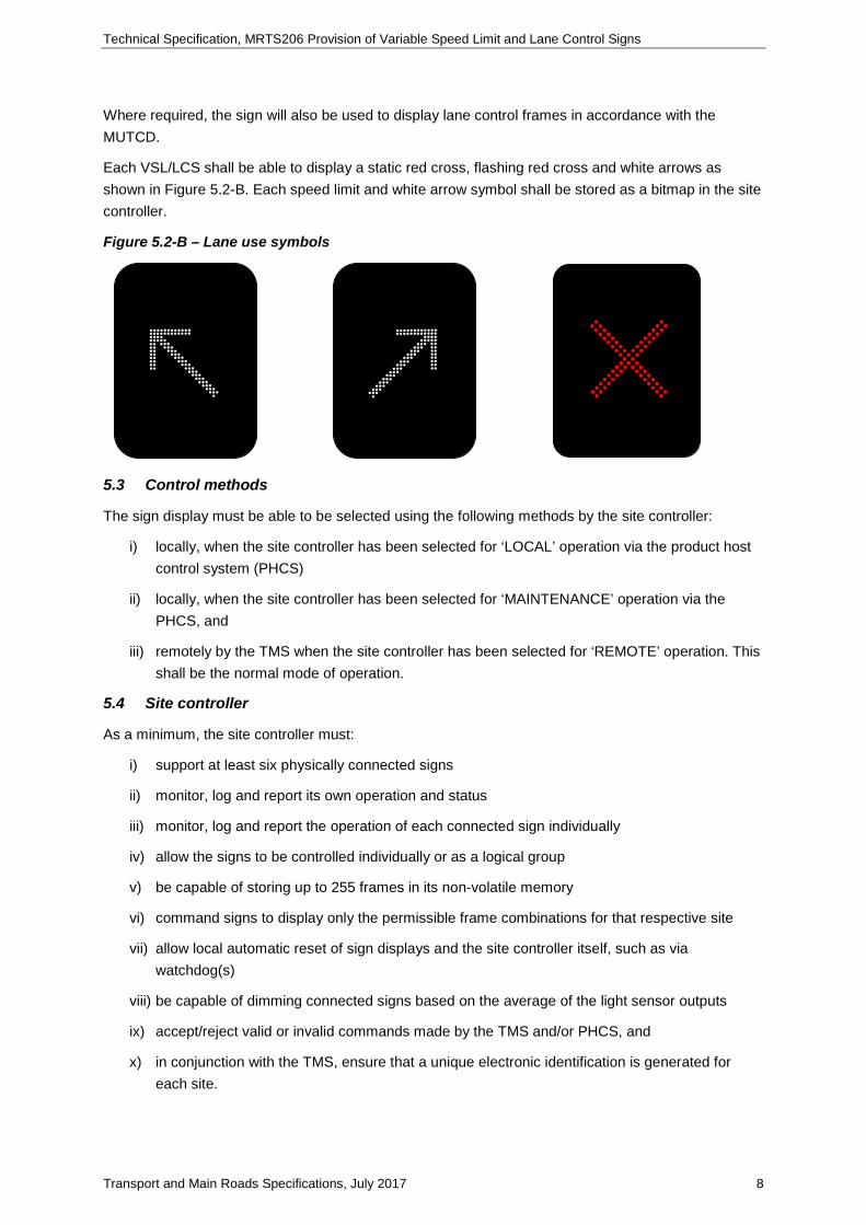
Where required, the sign will also be used to display lane control frames in accordance with the MUTCD.
Each VSL/LCS shall be able to display a static red cross, flashing red cross and white arrows as shown in Figure 5.2-B. Each speed limit and white arrow symbol shall be stored as a bitmap in the site controller.
Figure 5.2-B – Lane use symbols
5.3 Control methods
The sign display must be able to be selected using the following methods by the site controller:
i) locally, when the site controller has been selected for ‘LOCAL’ operation via the product host control system (PHCS)
ii) locally, when the site controller has been selected for ‘MAINTENANCE’ operation via the PHCS, and
iii) remotely by the TMS when the site controller has been selected for ‘REMOTE’ operation. This shall be the normal mode of operation.
5.4 Site controller
As a minimum, the site controller must:
i) support at least six physically connected signs
ii) monitor, log and report its own operation and status
iii) monitor, log and report the operation of each connected sign individually
iv) allow the signs to be controlled individually or as a logical group
v) be capable of storing up to 255 frames in its non-volatile memory
vi) command signs to display only the permissible frame combinations for that respective site
vii) allow local automatic reset of sign displays and the site controller itself, such as via watchdog(s)
viii) be capable of dimming connected signs based on the average of the light sensor outputs
ix) accept/reject valid or invalid commands made by the TMS and/or PHCS, and
x) in conjunction with the TMS, ensure that a unique electronic identification is generated for each site.
Technical Specification, MRTS206 Provision of Variable Speed Limit and Lane Control Signs
Transport and Main Roads Specifications, July 2017 9
Additional information and functionality of the site controller required is described in the following sections.
5.5 Frame display time
The minimum display duration of each frame shall be configurable and accessible via the PHCS. The time range and factory default settings are shown in Appendix B.
5.6 Flashing display control
The site controller shall command inner rings of the annulus to flash when speeds other than the site’s default speed (as confirmed by the Principal) are displayed. Where two or more signs are connected to the same site controller, the flashing elements of all signs at that site (including red cross) must flash in synchronisation. The site controller shall also provide the functionality to command a VSL/LCS to display a flashing cross. The flash rate and display cycle shall be configurable and factory default settings are shown in Appendix B.
5.7 Communications timeout
The site controller must be capable of monitoring loss of communications with the TMS and timeout after a specified period. When the site controller is in the ‘REMOTE’ mode, expiry of this time period must cause the site controller to blank all physically connected signs. This period shall be a configurable parameter and is denoted ‘Session timeout’. The range and factory default settings of session timeout are shown in Appendix B. The site controller must also be capable of monitoring communications with the signs connected to it and timeout after a specified period when such communication is lost. Communications timeout check shall be performed periodically as shown in Appendix B. In ‘LOCAL’ mode, the session timeout check with the TMS shall be ignored.
5.8 Permissible Frame Combinations (PFC) and rules
The site controller shall store only those frames permitted to be displayed at its respective site. It shall ensure that only permissible combinations of frames for that site are displayed on its respective signs.
The site controller shall generate, log and report an alarm if a frame display request by the TMS is for non-permissible frame(s) and/or combination of frames.
The site controller shall allow:
a) the PHCS to read and write its permitted frames and permitted frame combinations (PFC)
b) the TMS to read its stored frames and PFC, and
c) its stored frames to be downloaded to the sign(s) only as required to be displayed.
The permissible frames and PFC for each site shall be confirmed with the Principal. This includes the default, maximum and minimum speeds allowed at the respective VSL site.
The PFC at each site shall be determined in accordance with the following rules:
a) signs displaying speed must display the same speed
b) exit arrows shall not point towards each other
c) exit arrows are only allowed at the VSL site immediately upstream of an exit ramp
d) a left exit arrow may only be shown in the left lane(s), corresponding to the respective exit lane(s) available

Technical Specification, MRTS206 Provision of Variable Speed Limit and Lane Control Signs
Transport and Main Roads Specifications, July 2017 10
e) a right exit arrow may only be shown in the right lane(s), corresponding to the respective exit lane(s) available, and
f) generally, a VSL site shall not be blanked upon a fault on one or more signs, provided that there is a working sign adjacent to each faulty sign. However, a sign displaying a lane use symbol shall not be blanked even if there is no working sign adjacent to it.
5.9 Unique hardware identifiers
Each VSL site must be uniquely identifiable. A unique site hardware identifier must be implemented physically, external to the site controller, such as by jumper settings, dip switch, soldered bits or otherwise. The unique ID shall be permanently attached to the field cabinet. This ID must be able to be translated electronically through the site controller. A checksum unique to each site shall be computed based on the permitted frames, PFC and hardware site identifier to form the unique VSL site ID identifiable by the TMS.
The checksum shall be available for confirmation by the TMS that the permitted frames and PFC at each VSL site are the same as those stored at the TMC. The checksum shall be verified periodically and recomputed each time the permitted frames and/or PFC is changed and/or that the site controller is reset/rebooted.
5.10 Configuration management
All settings in the site controller, including settings included in Appendix B, the permissible frames and PFC must be accessible using the PHCS. The configuration shall be site-specific and must ensure that only the site controller with the correct configuration for the respective VSL site is allowed to control its respective VSL site.
The site-specific permitted frames, PFC and other user configurable settings shall be stored in non-volatile memory, such that they can be altered and downloaded from the PHCS without requiring any change to the site controller firmware.
5.11 Sign fault management
The site controller shall monitor and log the following sign conditions:
• loss of communication with the sign
• high sign enclosure temperature
• illumination faults, and
• other faults relating to the sign.
The log shall identify the sign and its respective fault.
Upon establishing connection to sign(s), power up, or after a mains power failure, the site controller shall immediately blank the respective sign(s) for a specified period and re-transmit the respective frame(s) to be displayed. The ‘Power recovery delay time’ shall be configurable and the range and factory default settings are shown in Appendix B.
The site controller must allow each sign’s display to remain blank for a minimum time once the display has been blanked irrespective of the cause. This minimum blank time and range is also shown in Appendix B.

Technical Specification, MRTS206 Provision of Variable Speed Limit and Lane Control Signs
Transport and Main Roads Specifications, July 2017 11
5.12 Local event logging
The site controller shall log in non-volatile memory all operational and fault events, such as speed changes, lane closure, hardware resets, establishment or discontinuation of communications, local manual operations and clearance of faults. Each event must be date and time stamped, accurate to at least one hundredth of a second. Once a fault has occurred and been logged, a recurrence of the same fault need not be logged again until after the fault has been cleared.
The event log shall have space for at least 255 entries. Where separate logs are used for operational and fault events, each log shall have space for at least 255 entries. The oldest event record shall be overwritten first when this allocated space has been exceeded.
All log entries must be available for upload from any and all communication ports upon request from the TMC and/or PHCS. The log shall be uploaded in order of most recent to oldest record. A request by the TMS for the event log shall provide for no less than 20 entries at a time.
Events shall be retained in the log even after retrieval by the PHCS and/or TMS.
5.13 Watchdog
The sign and site controller must each monitor the state of its respective processor and blank the respective display/s if processor failure occurs.
The site controller shall generate an alarm and blank all signs (including lane use symbols) if the integrity of the firmware or configuration is breached.
5.14 Time synchronisation
The site controller must allow synchronisation of its system clock in response to a TMS and/or PHCS command.
6 Mechanical and physical requirements
6.1 General
The mechanical and physical requirements defined in MRTS201 General Equipment Requirements apply to this Technical Specification. Additional mechanical and physical requirements for equipment provided under this Technical Specification are described below.
The sign and site controller must be constructed from durable materials to enable installation and reliable operations in the intended roadside and/or tunnel environment.
Unless otherwise specified, the design life of components must be as follows:
• LEDs/pixels: a minimum of five years
• other electrical systems: a minimum of 10 years
• sign enclosure: a minimum of 20 years, and
• structural supports: a minimum of 40 years.
6.2 Sign enclosure
The sign enclosure must house the sign displays and associated control electronics, and comply with the requirements of MRTS201 General Equipment Requirements. Where installed in a tunnel, the enclosure must be made of marine-grade aluminium.
Technical Specification, MRTS206 Provision of Variable Speed Limit and Lane Control Signs
Transport and Main Roads Specifications, July 2017 12
6.2.1 Doors
Access to the sign enclosure must be from the front. Rear doors may be provided on signs mounted on a traversable gantries to allow maintenance insitu without need for traffic control. Doors shall be hinged on the side and open, preferably from right to left.
6.2.2 Front cover
A protective front cover must be fitted to the VSLS and/or VSL/LCS enclosure to form a viewing window. The front cover material must be a single, clear Lexan® sheet or equivalent and have a non-reflective finish. The sheeting must be manufactured from sign-grade material SG300, with a thickness at least equal to that recommended by the manufacturer, with an absolute minimum of 4.5 mm. The viewing window must be such that when installed, the sides and bottom edges of the display face are fully visible at viewing angles of ± 45° (horizontal) and ± 60° (vertical) to the axis perpendicular to the front plane of the display.
The front cover must include a clear, non-reflective polycarbonate front screen. Suitable means must be provided to demist the front screen.
6.2.3 Front cover retention method
The front cover must be able to be removed for maintenance without requiring removal of internal components.
The front cover retention and seal design must allow for thermal expansion properties of the front cover material. The front cover surrounding framework and cover strips must provide the required weather proofing and strength for both positive and negative wind pressures, and, where applicable, tunnel deluge systems.
6.3 Mounting structure
Each VSLS must be capable of being pole-mounted in the verge or on the concrete barrier. Mounting on bridge/overpass structures shall be to the acceptance of the Principal’s representative.
Each VSL/LCS must be capable of being mounted centrally above each lane either on a cantilevered structure, a gantry or from a tunnel roof.
Where signs are mounted above a carriageway, the vertical clearance from the lowest surface of sign and the associated mounting structure must be a minimum of 6.1 metres or as otherwise specified in the design requirements.
The location and type of mounting structure to be provided for each site controller, sign and/or each group of signs must be shown on the design documentation. Mounting arrangements must provide means to adjust the vertical and/or horizontal alignment of each sign during commissioning and subsequent maintenance activities. Sign mounting components must allow replacement of the sign within five minutes. The mounting structure must comply with MRTS201.
Final footing, support structure design and locations as shown in design documentation shall be submitted to the Principal’s representative for acceptance before fabrication. Hold Point 3
6.4 Telecommunications field cabinets
All equipment associated with the site controller must be installed in a suitable roadside enclosure that complies with MRTS201 installed:
• as a ground mounted cabinet
Technical Specification, MRTS206 Provision of Variable Speed Limit and Lane Control Signs
Transport and Main Roads Specifications, July 2017 13
• as an integral enclosure installed on the mounting structure (VSL/LCS only), or
• in the case of tunnels, in a stainless steel or marine grade aluminium field cabinet mounted in accordance with the design documentation.
Pits and conduit must be installed in accordance with MRTS91 to provide cable access from the sign to the cabinet.
7 Operational requirements of sign displays
7.1 General
The operational requirements defined in MRTS201 General Equipment Requirements apply to this Technical Specification. Additional operational requirements for equipment provided under this Technical Specification are described below.
The sign numeric and/or arrow displays must be based on a series of pixels forming a dot matrix display system. The horizontal and vertical pitch of the pixels in the matrix must be the same. The Lane Closed ‘X’ and annulus display elements may be specifically arranged. The apparent width of all displayed elements, including text, must match the respective sign display defined in the MUTCD.
The display pixels must be provided in modules of a size capable of being removed and installed in situ by hand via the access door(s).
The type, A, B, C or D as defined by the MUTCD of sign required must be as specified on the design documentation. The display must be physically capable of displaying speeds from 20 km/h up to the maximum speed for the VSL site in 10 km/h increments. The actual speed range for each site must be confirmed with the Principal during the commissioning activities and retained as part of the non-volatile information stored in the site controller. Only those frames permitted to be displayed at the site of installation shall be programmed into the site controller.
7.2 Display technology
The display technology must be light emitting diode (LED). To achieve the required sign luminance levels, the display pixels may be formed by arranging one or more LEDs in a cluster.
7.3 LED output
Each individual LED must be driven with a continuous current, with no peak and/or magnitudes exceeding 70% of the LED manufacturer's maximum continuous rating.
7.4 Character formats
The display of numerals for the purpose of speed regulation and information must comply as much as practicable with the fonts defined in MUTCD. Numerals must meet the fonts defined for use on a Regulatory Sign R4-1.
The annulus must not be less in size than that required for an equivalent static sign.
The minimum legibility (sight) distance and character height must be as indicated in Table 7.4 for both daytime and night-time viewing. This distance does not reduce the absolute minimum clear sight distance as described in TRUM Manual.
Technical Specification, MRTS206 Provision of Variable Speed Limit and Lane Control Signs
Transport and Main Roads Specifications, July 2017 14
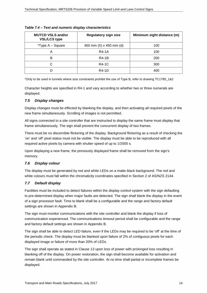
Table 7.4 – Text and numeric display characteristics
MUTCD VSLS and/or VSL/LCS type
Regulatory sign size Minimum sight distance (m)
*Type A – Square 450 mm (h) x 450 mm (d) 100
A R4-1A 100
B R4-1B 200
C R4-1C 300
D R4-1D 400 *Only to be used in tunnels where size constraints prohibit the use of Type B, refer to drawing TC1785_1&2 Character heights are specified in R4-1 and vary according to whether two or three numerals are displayed.
7.5 Display changes
Display changes must be effected by blanking the display, and then activating all required pixels of the new frame simultaneously. Scrolling of images is not permitted.
All signs connected to a site controller that are instructed to display the same frame must display that frame simultaneously. The sign shall prevent the concurrent display of two frames.
There must be no discernible flickering of the display. Background flickering as a result of checking the ‘on’ and ‘off’ pixel status must not be visible. The display must be able to be reproduced with all required active pixels by camera with shutter speed of up to 1/2000 s.
Upon displaying a new frame, the previously displayed frame shall be removed from the sign’s memory.
7.6 Display colour
The display must be generated by red and white LEDs on a matte black background. The red and white colours must fall within the chromaticity coordinates specified in Section 2 of AS/NZS 2144.
7.7 Default display
Facilities must be included to detect failures within the display control system with the sign defaulting to pre-determined display when major faults are detected. The sign shall blank the display in the event of a sign processor fault. Time to blank shall be a configurable and the range and factory default settings are shown in Appendix B.
The sign must monitor communications with the site controller and blank the display if loss of communication experienced. The communications timeout period shall be configurable and the range and factory default settings are shown in Appendix B.
The sign shall be able to detect LED failure, even if the LEDs may be required to be ‘off’ at the time of the periodic check. The display must be blanked upon failure of 2% of contiguous pixels for each displayed image or failure of more than 20% of LEDs.
The sign shall operate as stated in Clause 13 upon loss of power with prolonged loss resulting in blanking off of the display. On power restoration, the sign shall become available for activation and remain blank until commanded by the site controller. At no time shall partial or incomplete frames be displayed.
Technical Specification, MRTS206 Provision of Variable Speed Limit and Lane Control Signs
Transport and Main Roads Specifications, July 2017 15
Single LED failure, provided that the cumulative LED loss remains below the 2% and/or 20% thresholds described above or VSL/LCS light sensor failure, should not result in blanking of the display.
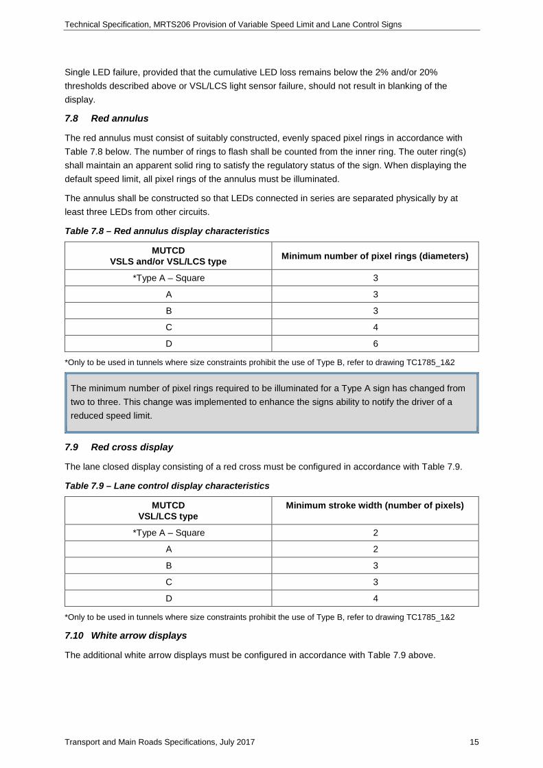
7.8 Red annulus
The red annulus must consist of suitably constructed, evenly spaced pixel rings in accordance with Table 7.8 below. The number of rings to flash shall be counted from the inner ring. The outer ring(s) shall maintain an apparent solid ring to satisfy the regulatory status of the sign. When displaying the default speed limit, all pixel rings of the annulus must be illuminated.
The annulus shall be constructed so that LEDs connected in series are separated physically by at least three LEDs from other circuits.
Table 7.8 – Red annulus display characteristics
MUTCD VSLS and/or VSL/LCS type Minimum number of pixel rings (diameters)
*Type A – Square 3
A 3
B 3
C 4
D 6
*Only to be used in tunnels where size constraints prohibit the use of Type B, refer to drawing TC1785_1&2
The minimum number of pixel rings required to be illuminated for a Type A sign has changed from two to three. This change was implemented to enhance the signs ability to notify the driver of a reduced speed limit.
7.9 Red cross display
The lane closed display consisting of a red cross must be configured in accordance with Table 7.9.
Table 7.9 – Lane control display characteristics
MUTCD VSL/LCS type
Minimum stroke width (number of pixels)
*Type A – Square 2
A 2
B 3
C 3
D 4
*Only to be used in tunnels where size constraints prohibit the use of Type B, refer to drawing TC1785_1&2
7.10 White arrow displays
The additional white arrow displays must be configured in accordance with Table 7.9 above.
Technical Specification, MRTS206 Provision of Variable Speed Limit and Lane Control Signs
Transport and Main Roads Specifications, July 2017 16
7.11 Flashing display elements
The sign shall allow selectable flashing of the whole and/or part of the display via all the communications ports. The flash rate parameters must be configurable and also be selectable via all of the communications ports as specified in Appendix B.
7.11.1 Flashing partial annulus
The red annulus must be designed so that the inner diameter(s) of the annulus can be flashed as an independent event.
When displaying other than the normal speed, the outer ring of the red annulus shall always be static to satisfy the regulatory status of the sign, while all the other inner rings shall be flashing.
The above changes in 7.11.1 have been agreed to by Transport and Main Roads and the Austroads review committee: (Project No: NS1929, Review of Sign Size for Electronic Regulatory Speed Signs, 008558 – August 2014)
The change has been made on the basis that the more rings that flash, the more likely drivers’ attention would be drawn to the sign.
7.12 Bitmap display
The bitmap matrix for different fonts must be white in colour. Only fonts accepted by the Principal’s Representative shall be used.
7.13 Conspicuity devices
No conspicuity devices or lanterns are required. However, the sign shall allow conspicuity devices to be added in future if desired.
7.14 Internal clock
Each sign must be provided with a 24-hour internal clock. The clock must be able to be synchronised with the system clock derived from the site controller and/or PHCS. The clock must synchronise after hard restart, soft reboot or communications reestablishment.
8 Optical performance
8.1 Test procedures
The optical performance must be determined by measurement under laboratory conditions of the following parameters listed in Tables 8.2 and 8.3:
• minimum luminance ratio
• minimum and maximum luminance and luminous intensity uniformity
• viewing angle, and
• colour as per AS/NZS 2144.
The performance of the VSLS and VSL/LCS displays must meet or exceed the parameters listed in Table 8.2. Witness Point 1
Technical Specification, MRTS206 Provision of Variable Speed Limit and Lane Control Signs
Transport and Main Roads Specifications, July 2017 17
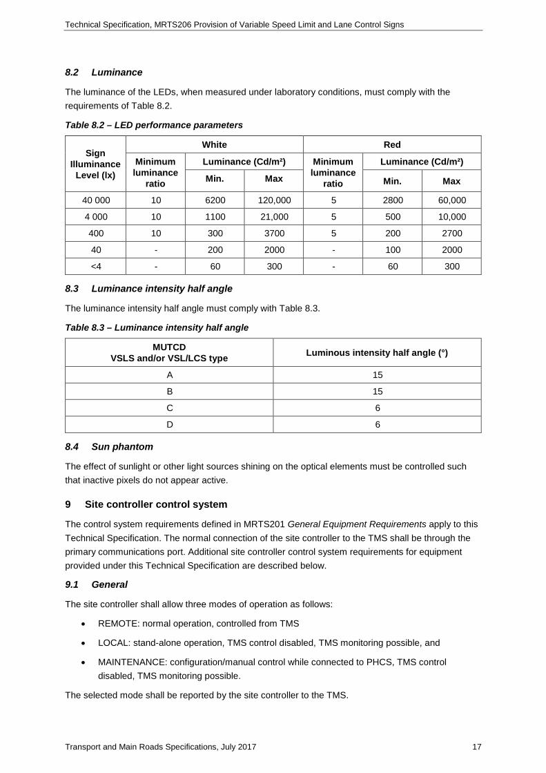
8.2 Luminance
The luminance of the LEDs, when measured under laboratory conditions, must comply with the requirements of Table 8.2.
Table 8.2 – LED performance parameters
Sign Illuminance
Level (lx)
White Red
Minimum luminance
ratio
Luminance (Cd/m²) Minimum luminance
ratio
Luminance (Cd/m²)
Min. Max Min. Max
40 000 10 6200 120,000 5 2800 60,000
4 000 10 1100 21,000 5 500 10,000
400 10 300 3700 5 200 2700
40 - 200 2000 - 100 2000
<4 - 60 300 - 60 300
8.3 Luminance intensity half angle
The luminance intensity half angle must comply with Table 8.3.
Table 8.3 – Luminance intensity half angle
MUTCD VSLS and/or VSL/LCS type Luminous intensity half angle (°)
A 15
B 15
C 6
D 6
8.4 Sun phantom
The effect of sunlight or other light sources shining on the optical elements must be controlled such that inactive pixels do not appear active.
9 Site controller control system
The control system requirements defined in MRTS201 General Equipment Requirements apply to this Technical Specification. The normal connection of the site controller to the TMS shall be through the primary communications port. Additional site controller control system requirements for equipment provided under this Technical Specification are described below.
9.1 General
The site controller shall allow three modes of operation as follows:
• REMOTE: normal operation, controlled from TMS
• LOCAL: stand-alone operation, TMS control disabled, TMS monitoring possible, and
• MAINTENANCE: configuration/manual control while connected to PHCS, TMS control disabled, TMS monitoring possible.
The selected mode shall be reported by the site controller to the TMS.
Technical Specification, MRTS206 Provision of Variable Speed Limit and Lane Control Signs
Transport and Main Roads Specifications, July 2017 18
Upon restoration of power after a power loss and/or reset, the site controller shall revert to the mode to which it was previously selected.
When the PHCS is connected, the site controller shall automatically change to ‘MAINTENANCE’ mode and blank all signs. The PHCS operator must enter an electronic password in order to select desired ‘LOCAL’/’REMOTE’ operation, change the site controller configuration and/or sign displays. A one-time password shall be generated at the TMC and conveyed verbally to authorised field personnel at the VSL site.
Once the PHCS operator has successfully logged on, the signs shall remain blanked unless specifically requested through the PHCS.
Upon disconnection of the PHCS, the site controller shall blank all signs and revert to the previously selected mode of operation, unless a different mode had been selected during the PHCS session. Where the site controller is selected (or reverts) to ‘LOCAL mode’, then the signs shall display the required frames. Where the site controller is selected (or reverts) to ‘REMOTE’ mode, the signs shall remain blank until the TMS commands otherwise.
Sign displays must comply with the respective PFC in all modes of operation.
Unless otherwise advised by the Principal, the site controller and sign shall be programmed with the factory defaults shown in Appendix B.
The site controller shall be controlled in the following order of priority when the ‘REMOTE’ mode is selected:
1. Maintenance communications port: once connected, the port has priority over the primary and secondary control communications ports. While the PHCS is connected, the primary control communications port or secondary control communications port must have the ability to eavesdrop, but not control, the VSL site.
2. Secondary control communications port: a session through the secondary control communications port has priority over the primary control port. Control reverts to the primary control port when a session via the secondary control port is terminated.
3. Primary Control communications port
a. Software must be provided in accordance with Clause 9.4.
9.2 Maintenance communications port
It must be possible to control and interrogate the site controller and signs via the site controller EIA/RS-232 maintenance communications port locally or remotely using the PHCS. This port shall also support remote connection to the TMC in case of failure of both communications ports.
Where specified in the project specific requirements, a modem must be provided with each site controller for remote data communications. The modem(s) must comply with MRTS201 General Equipment Requirements.
If the site controller is in the ‘MAINTENANCE’ mode, disconnection of the PHCS must not require further interaction from the user, nor in anyway interrupt operation or require rebooting of the site controller.
Technical Specification, MRTS206 Provision of Variable Speed Limit and Lane Control Signs
Transport and Main Roads Specifications, July 2017 19
The hardware handshaking lines of the EIA/RS-232 interface shall be used such that connection/ disconnection of the maintenance PC (either locally or by modem) results in the immediate initiation/ termination respectively of the maintenance port communications session with the site controller.
The site controller communications software must be capable of operating at all possible modem connection and/or serial port speeds.
9.3 Control communications ports
It must be possible to control and interrogate the site controller via either of two EIA/RS-422 control communications ports, the primary and secondary. The secondary control communications port shall generally have a higher priority than the primary communication port. Each control communications port must allow local connection of a field processor/modem for communication with the TMS.
Where specified in the project specific requirements, a modem must be provided with each site controller for remote data communications. The modem(s) must comply with MRTS201 General Equipment Requirements. The Contractor must provide an EIA/RS-422 interface to connect to the modem(s) as necessary.
The site controller communications software must be capable of operating at all possible modem connection and/or serial port speeds.
While the PHCS is connected to the site controller, control of the site controller via the control ports must be inhibited. However, status and diagnostic interrogation by the TMS via the control ports must remain possible.
Complete control and monitoring by the TMS shall be possible through either and/or both control communications ports as determined by telecommunications infrastructure provided at each site.
Where communications equipment is connected to both control communications ports, the secondary port shall be used for control commands to/from the TMC. The primary port shall be automatically selected to communicate with the TMC upon failure or disconnection of the secondary communications port. In case of failure of the maintenance communications port, the PHCS shall be able to communicate with the site controller via the primary and/or secondary communications ports.
9.4 Product Host Control System – control/diagnostics software
A PHCS shall be supplied with the site controller and signs for the purpose of site controller and sign configuration, commissioning and maintenance activities. The PHCS shall also allow setting of the site controller mode of operation. The PHCS must fully implement all site controller and sign functions as required by Clause 9.7 for each of the maintenance communications and control communications ports.
The PHCS shall be configured to request passwords as part of the signs controller access and configuration authorisation process.
The PHCS shall be hosted on a Microsoft Windows® operating system environment from XP to those industry standards current at the time of use. Any software provided must be capable of operating on all such operating systems.
The PHCS must be able to present to the user a graphic image of the site controller and the signs connected to it with icons or features that indicate whether there are any alarms or faults on any of the devices.
The software must prompt the user to confirm a change to the site controller’s mode of operation.
Technical Specification, MRTS206 Provision of Variable Speed Limit and Lane Control Signs
Transport and Main Roads Specifications, July 2017 20
The PHCS shall be capable of suggesting ranges for each parameter as applicable when programming and not allow these limits to be exceeded. The PHCS shall allow batch processing of site controller configuration for the respective VSL sites.
The PHCS shall have a test program to facilitate testing of all the essential sign features, including ability to activate, deactivate all pixels and vary LED brightness. Capability to display and store on file a mimic of the sign showing defective LEDs is required.
The software must allow querying of events according to set criteria, such as by sign(s), time, date, event type or by duration.
9.5 LED intensity control
The site controller must be able to vary the sign display brightness based on the output of the light sensors connected to it or based on the average of the light sensor outputs of the signs connected to it. It must allow a bias to be applied to attempt matching, such that signs connected to the same site controller appear to have the same brightness irrespective of age/condition of the LEDs.
The site controller must also provide the ability to manually control sign LED brightness as directed by the TMS. Section 10.4 contains more information on LED intensity control.
9.6 Temperature control
The site controller must have the ability to provide to the TMS temperature readings obtained from the signs connected to it.
9.7 Communication protocol
Communication between the field processor and the site controller must comply with TSI-SP-003 or other protocol accepted by the Principal’s Representative and the requirements of MRTS201 General Equipment Requirements. The site controller must have session management ability in order to protect the system against unauthorised access via the communications ports.
9.8 Bus arbitration
The site controller must act as slave to the FP/modem bus.
10 Sign control system
The control system requirements defined in MRTS201 General Equipment Requirements apply to this Technical Specification. Additional control system requirements for equipment provided under this Technical Specification are described below.
10.1 General
Each sign shall be directly connected to the site controller using a unique EIA/RS-422 serial communications port. Tool-free connectors offering physical security as that offered by RJ-45 connectors or better must be used for this purpose. The connectors must be rated to at least IP56 with mechanical latching or strain relief.
The sign communications port must provide all the functionality required for the sign to be controlled and monitored by the site controller.
Where a maintenance communication port is provided in the sign, it shall have higher priority over the sign’s control communications port. Control shall revert to the control communications port once its
Technical Specification, MRTS206 Provision of Variable Speed Limit and Lane Control Signs
Transport and Main Roads Specifications, July 2017 21
maintenance port is not in use. Each sign must have the ability to self-monitor pixel faults, temperature and service status requests from the site controller.
10.2 Sign maintenance communications port
The maintenance communications port must allow interrogation and of the sign using the PHCS.
10.3 Sign control communications port
The sign shall be connected to the site controller using this port. The communications protocol must be such that full functionality of the site controller as described above is supported.
10.4 LED intensity control
The LED intensity must be controlled to provide constant apparent brightness and maximum legibility distance for the complete range of ambient light under which each sign must operate.
Each sign must be capable of providing automatic brightness variation where the sign determines the LED brightness level using a light sensor reading and a predefined set of light sensor values. In addition, each sign must allow brightness variation to be set by the site controller to which it is connected. In this case, each sign shall make available the light sensor output to the site controller to facilitate dimming of signs as a group.
The sign must have at least 16 brightness levels. The brightness levels must be in units of percentage of maximum brightness.
Each sign must provide at least two light sensors to detect ambient light levels. These sensors must be located as follows:
• one sensor facing forward perpendicular to the sign face, and
• one sensor facing backward perpendicular to the sign face.
The sign shall be capable of reporting light sensor fault to the site controller. A sign mounted directly against a gantry or in a tunnel where provision of more than one sensor may not result in additional benefits, may be equipped with one sensor.
10.5 Temperature control
Each sign must provide at least one temperature sensor to measure the temperature inside the enclosure at points of high thermal stress. The sensor must not be mounted directly against the top face of the enclosure. The temperature reading data must be transmitted to the communications port. The temperature must be in units of (°C).
10.6 Bus arbitration
The sign must act as a slave on the site controller EIA/RS-422/modem bus.
11 Installation requirements
The installation requirements defined in MRTS201 General Equipment Requirements apply to this Technical Specification. Additional installation requirements relevant under this Technical Specification are described below.
a) The general layout, positions, reduced level for the footing (where applicable), and speed zones for the VSLS and/or VSL/LCS and details of the barrier and other mounting requirements must be as shown on the design documentation.

Technical Specification, MRTS206 Provision of Variable Speed Limit and Lane Control Signs
Transport and Main Roads Specifications, July 2017 22
b) The position of in-ground mounting structures must comply with the requirements of the MUTCD.
c) The positioning of VSLS and/or VSL/LCS must provide sight distances as described in the TRUM Manual.
d) The VSLS and/or VSL/LCS location must be verified by site inspection and must be shown on the design documentation. The design documentation must be submitted to the Administrator not less than seven days prior to the commencement of civil works for the VSLS and/or VSL/LCS foundations. Milestone
Before installation, the Contractor must confirm the final VSLS and/or VSL/LCS location and the type, location and positioning of the mounting arrangements and/or protection barrier as shown in the design documentation to the Administrator.
12 Environmental
The environmental requirements defined in MRTS201 General Equipment Requirements apply to this Technical Specification.
13 Electrical
The electrical requirements defined in MRTS201 General Equipment Requirements apply to this Technical Specification.
The sign must be able to operate normally even with voltage variation of -13% to +10% in the 230V mains supply. Momentary voltage loss of 50 ms shall not have any effect on the sign display and/or site controller.
Battery back-up shall be provided for the real-time clock and processor to allow orderly power down in the case of loss of power supply.
Power supply and control wiring connection/disconnection shall be possible by all personnel without the requirement of holding an electrical licence to perform this task.
14 ITS network telecommunications
The telecommunications requirements defined in MRTS201 General Equipment Requirements apply to this Technical Specification.
15 Testing and commissioning
15.1 General
The testing and commissioning requirements defined in MRTS201 General Equipment Requirements apply to this Technical Specification. Additional testing and commissioning requirements relevant under this Technical Specification are described below.
15.2 Factory acceptance tests
Compliance with the optical performance requirements must be determined by measurement under laboratory conditions of the parameters listed in Table 8.2 and Table 8.3 as detailed in Clause 8. Witness Point 2
Technical Specification, MRTS206 Provision of Variable Speed Limit and Lane Control Signs
Transport and Main Roads Specifications, July 2017 23
15.3 Test VSLS and/or VSL/LCS
A test VSLS and/or VSL/LCS complete with site controller must be provided to the Principal as part of the STREAMS Acceptance Test Plan (SAT) for testing of software components used to control the VSLS and/or VSL/LCS within the ITS Network. Provision of the test VSLS and/or VSL/LCS will not be necessary if a test VSLS and/or VSL/LCS has previously passed a SAT or if the Principal specifies otherwise.
The test sign for the STREAMS Acceptance Test Plan may be a smaller version of the sign to be supplied under the contract. It must, however, be functionally equivalent with identical communications interface and operations.
15.4 Configuring frames
Permissible frame combinations shall be configured as part of the commissioning process. The maximum speed limits for speeds set in local control mode shall not exceed the otherwise statically signed speed limit for that location.
16 Documentation
The documentation requirements defined in MRTS201 General Equipment Requirements apply to this Technical Specification.
17 Training
The training requirements defined in MRTS201 General Equipment Requirements apply to this Technical Specification.
18 Maintenance
The maintenance requirements defined in MRTS201 General Equipment Requirements apply to this Technical Specification.
19 Handover
The handover requirements defined in MRTS201 General Equipment Requirements apply to this Technical Specification.
Technical Specification, MRTS206 Provision of Variable Speed Limit and Lane Control Signs
Transport and Main Roads Specifications, July 2017 24
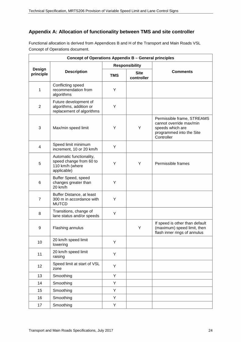
Appendix A: Allocation of functionality between TMS and site controller
Functional allocation is derived from Appendices B and H of the Transport and Main Roads VSL Concept of Operations document.
Concept of Operations Appendix B – General principles
Design principle Description
Responsibility Comments
TMS Site controller
1 Conflicting speed recommendation from algorithms
Y
2 Future development of algorithms, addition or replacement of algorithms
Y
3 Max/min speed limit Y Y
Permissible frame, STREAMS cannot override max/min speeds which are programmed into the Site Controller
4 Speed limit minimum increment, 10 or 20 km/h Y
5
Automatic functionality, speed change from 60 to 110 km/h (where applicable)
Y Y Permissible frames
6 Buffer Speed, speed changes greater than 20 km/h
Y
7 Buffer Distance, at least 300 m in accordance with MUTCD
Y
8 Transitions, change of lane status and/or speeds Y
9 Flashing annulus Y If speed is other than default (maximum) speed limit, then flash inner rings of annulus
10 20 km/h speed limit lowering Y
11 20 km/h speed limit raising Y
12 Speed limit at start of VSL zone Y
13 Smoothing Y
14 Smoothing Y
15 Smoothing Y
16 Smoothing Y
17 Smoothing Y
Technical Specification, MRTS206 Provision of Variable Speed Limit and Lane Control Signs
Transport and Main Roads Specifications, July 2017 25
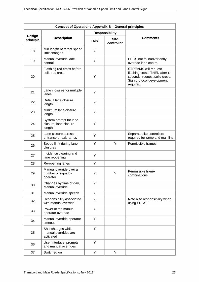
Concept of Operations Appendix B – General principles
Design principle Description
Responsibility Comments
TMS Site controller
18 Min length of target speed limit changes Y
19 Manual override lane control Y PHCS not to inadvertently
override lane control
20
Flashing red cross before solid red cross
Y
STREAMS will request flashing cross, THEN after x seconds, request solid cross. Sign protocol development required
21 Lane closures for multiple lanes Y
22 Default lane closure length Y
23 Minimum lane closure length Y
24 System prompt for lane closure, lane closure length
Y
25 Lane closure across entrance or exit ramps Y Separate site controllers
required for ramp and mainline
26 Speed limit during lane closures
Y Y Permissible frames
27 Incidence clearing and lane reopening Y
28 Re-opening lanes Y
29 Manual override over a number of signs by operator
Y Y Permissible frame combinations
30 Changes by time of day, Manual override
Y
31 Manual override speeds Y
32 Responsibility associated with manual override
Y Note also responsibility when using PHCS
33 Power of the manual operator override
Y
34 Manual override operator timeout
Y
35 Shift changes while manual overrides are activated
Y
36 User interface, prompts and manual overrides
Y
37 Switched on Y Y
Technical Specification, MRTS206 Provision of Variable Speed Limit and Lane Control Signs
Transport and Main Roads Specifications, July 2017 26
Concept of Operations Appendix B – General principles
Design principle Description
Responsibility Comments
TMS Site controller
38 Manage different directions separately
Y
39 Appropriate sign displays for safety
Y Permissible frame combinations
40 Confirmation that sign display has changed
Y Y Sign protocol
41 Generic plans for incident management
Y
42 Sign interlocking, mainline/entrance ramp
Y Ramp signs to have own controller
43 Queuing object Y
44 Auditing email account Y
45 Calibration, fine tuning of algorithms
Y
46 Management of parameters
Y
47
Interaction with STREAMS incident management system (SIMS)
Y
48 Differential lane speeds n/a Possible
future (by others)
Permissible frame combinations
49 Sign spacing Y
50 Optimum location beyond on ramp taper
Y
51 Unobstructed viewing distance
Y
52 Default speed limit (when VSL system is not available)
n/a n/a Static signs
Concept of Operations Appendix H – Fault Management
Design principle Description
Responsibility Comments
TMS Site controller
1 VSL/LCS displays incorrect symbol
Y
2 Inability to determine VSL/LCS display
Y Watchdog timer
3 System operator alert Y Protocol to allow
Technical Specification, MRTS206 Provision of Variable Speed Limit and Lane Control Signs
Transport and Main Roads Specifications, July 2017 27
Concept of Operations Appendix H – Fault Management
Design principle Description
Responsibility Comments
TMS Site controller
4 Failure of pole-mounted VSL at VSL zone entry
Y Y Solution will now be through the hardware (Previously in STREAMS)
5 Failure of pole-mounted VSL where upstream VSL site displays same speed
Y
6
Failure of pole-mounted VSL where upstream VSL site displays slower speed than the faulty site
Y
7
Failure of pole-mounted VSL where upstream VSL site displays faster speed than the faulty site
Y
8 Failure of gantry-mounted VSL signs (at VSL zone entry)
Y Y Solution now to be through hardware (site controller)
9
Failure of gantry-mounted VSL signs where upstream VSL site displays same speed
Y
10
Failure of gantry-mounted VSL signs where upstream VSL site displays slower speed
Y
11
Failure of gantry-mounted VSL signs where upstream VSL site displays faster speed than faulty site
Y
12 Maximum uptime without communications
Y Y Set in STREAMS
13 Power recover delay time Y Hardware waits for instruction from STREAMS
14 Sign display minimum downtime
Y
15 Maximum rollback Y
16 Non-consecutive faulty sites
Y
17 Rollback onto upstream motorways
Y
18 Rollback scheme for lane closure
Y
19 Rollback scheme for lane closure zone
Y
Technical Specification, MRTS206 Provision of Variable Speed Limit and Lane Control Signs
Transport and Main Roads Specifications, July 2017 28
Concept of Operations Appendix H – Fault Management
Design principle Description
Responsibility Comments
TMS Site controller
20 Failure of interlocked signs, mainline entry ramp
Y
Technical Specification, MRTS206 Provision of Variable Speed Limit and Lane Control Signs
Transport and Main Roads Specifications, July 2017 29
Appendix B: Referenced variables and default settings
Reference Description Range of values
Factory default
Device(s), systems affected
5.5 Frame display time 1 -5 seconds 5 s Site controller/sign
5.6 Flashing display elements 10-90% lit 1 s cycle time 60% lit (40% unlit)
Site controller/sign
5.7 Session timeout – (site controller /TMS)
1-600 seconds 60 s Site controller /TMC
5.7 Communications check with sign
0-30 seconds Once every 5 s
Site controller
5.11 Power recovery delay time 1-600 seconds 60 Site controller/sign
5.11 Minimum blank time 1-120 seconds 30 Site controller/sign
7.7 Sign processor fault blank time 0.5-3 seconds 1 s Sign
7.7 Communication timeout – (sign/ site controller)
1-600 60 Sign
10.4 LED intensity control 1-16 levels Dimming by SC
Site controller/sign
Technical Specification, MRTS206 Provision of Variable Speed Limit and Lane Control Signs
Transport and Main Roads Specifications, July 2017 30
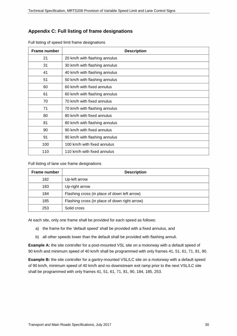
Appendix C: Full listing of frame designations
Full listing of speed limit frame designations
Frame number Description
21 20 km/h with flashing annulus
31 30 km/h with flashing annulus
41 40 km/h with flashing annulus
51 50 km/h with flashing annulus
60 60 km/h with fixed annulus
61 60 km/h with flashing annulus
70 70 km/h with fixed annulus
71 70 km/h with flashing annulus
80 80 km/h with fixed annulus
81 80 km/h with flashing annulus
90 90 km/h with fixed annulus
91 90 km/h with flashing annulus
100 100 km/h with fixed annulus
110 110 km/h with fixed annulus Full listing of lane use frame designations
Frame number Description
182 Up-left arrow
183 Up-right arrow
184 Flashing cross (in place of down left arrow)
185 Flashing cross (in place of down right arrow)
253 Solid cross At each site, only one frame shall be provided for each speed as follows:
a) the frame for the ‘default speed’ shall be provided with a fixed annulus, and
b) all other speeds lower than the default shall be provided with flashing annuli.
Example A: the site controller for a post-mounted VSL site on a motorway with a default speed of 90 km/h and minimum speed of 40 km/h shall be programmed with only frames 41, 51, 61, 71, 81, 90.
Example B: the site controller for a gantry-mounted VSL/LC site on a motorway with a default speed of 90 km/h, minimum speed of 40 km/h and no downstream exit ramp prior to the next VSL/LC site shall be programmed with only frames 41, 51, 61, 71, 81, 90, 184, 185, 253.