specification for helical anchorage€¦ · web viewthis document was developed by the helical...
TRANSCRIPT

MODEL SPECIFICATION
HELICAL PILE FOUNDATIONSCOMPRESSION APPLICATIONS
Prepared by theHelical Foundations and Tiebacks Committee
ofThe Deep Foundations Institute
First Edition1st Printing, 2015
Deep Foundations Institute326 Lafayette Avenue
Hawthorne, New Jersey 07506 USAwww.dfi.org
Copyright, 2015Deep Foundations Institute
Printed in USA
PREFACE AND ACKNOWLEDGEMENTS
This document was prepared by the Deep Foundations Institute (DFI) Helical Piles and Tiebacks Committee. If you have received this document from a source other than by purchase from DFI, please contact DFI at (973) 423-4030 to officially purchase this document and support the future
foundation developments of DFI. It is a violation of the copyright to distribute this document to others.
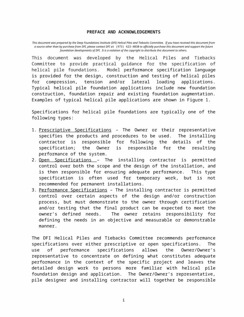
This document was developed by the Helical Piles and Tiebacks Committee to provide practical guidance for the specification of helical pile foundations. Model performance specification language is provided for the design, construction and testing of helical piles for compression, tension and/or lateral loading applications. Typical helical pile foundation applications include new foundation construction, foundation repair and existing foundation augmentation. Examples of typical helical pile applications are shown in Figure 1.
Specifications for helical pile foundations are typically one of the following types:
1. Prescriptive Specifications – The Owner or their representative specifies the products and procedures to be used. The installing contractor is responsible for following the details of the specification; the Owner is responsible for the resulting performance of the system.
2. Open Specifications – The installing contractor is permitted control over both the scope and the design of the installation, and is then responsible for ensuring adequate performance. This type specification is often used for temporary work, but is not recommended for permanent installations.
3. Performance Specifications – The installing contractor is permitted control over certain aspects of the design and/or construction process, but must demonstrate to the owner through certification and/or testing that the final product can be expected to meet the owner’s defined needs. The owner retains responsibility for defining the needs in an objective and measurable or demonstrable manner.
The DFI Helical Piles and Tiebacks Committee recommends performance specifications over either prescriptive or open specifications. The use of performance specifications allows the Owner/Owner’s representative to concentrate on defining what constitutes adequate performance in the context of the specific project and leaves the detailed design work to persons more familiar with helical pile foundation design and application. The Owner/Owner’s representative, pile designer and installing contractor will together be responsible for the tasks associated with the design, installation, acceptance and performance of the helical pile. It is important to clearly define the roles and responsibilities of every party on each project to promote good communication and reduce potential for contractual misunderstandings.
The installation of helical pile foundations requires specialized equipment, techniques and appropriate workmanship. To specify every important detail of the work would be both burdensome for the specifier and oppressive for the installing contractor. The Owner’s needs can be more effectively served by specifying the required performance, selecting competent helical pile designers and installing contractors to carry out the work, and auditing the work with an appropriate level of testing. The following Model Specification is written as a performance specification, but can be modified to an open or prescriptive specification if necessary.
The Helical Piles and Tiebacks Committee acknowledges former chairmen Dr. Samuel Clemence, Robert Hoyt, and Dr. Howard Perko for their leadership and contributions in the writing and editing of this specification.
Gary L. Seider, P.E., Chair, DFI Helical Piles and Tiebacks Committee
i

a) b)
c) d)
Figure 1. Examples of helical pile foundation applications (a) structural support for walkway/bridge, c) structural support for new building construction, c) foundation repair/retrofit,
d) structural support compression of tower/signage foundation,
ii

2015 Deep Foundations InstituteHelical Piles and Tiebacks Committee
Chair:Gary L. Seider, P.E. Hubbell Power Systems, Inc. / Chance®
Immediate Past Chair:Howard A. Perko, Ph.D. P.E. Magnum Piering Inc.
Trustee Liaison:Alan Roach Berkel and Company Contractors, Inc.
Current Members:Yasser Abdelghany, P.Eng., Ph.D Ministry of Transportation & InfrastructureSalah Al Dilimi Road and Transport Authority (RTA)Garett D. Bell Patriot Foundation SystemsLuis Berrospid Helical Anchors Inc.Bill Bonekemper Helical Pile World LLCJohn Boulware, Jr. Brackett Foundation Support Systems Inc.Tom Bradka, M.Eng., P.Eng Helical Pier SystemsDavid A. Bruce Hubbell Power Systems, Inc. / ChanceMark Bryant, EIT Maclean Power Systems Civil Products GroupJames A. Cherry, P.E.Samuel P. Clemence, Ph.D. Syracuse UniversityFrank D'Angelo Danbro DistributorsSteve Davidow P.E., S.E. Crux Subsurface Inc.Don Deardorff, P.E. Foundation Supportworks Inc.Bernard Dwyer, Jr. Magnum Piering Inc.Raja El-Awar P.E. FES Group, LLCMohamed Elkasabgy, Ph.D., P.Eng. AMEC E&INick Farkas Grip-Tite Mfg. Co. LLCMatt Houliston Magnum Piering Inc.Mike Jennings Maclean Power Systems Civil Products GroupKevin Kaufman Piertech SystemsGreg Keefer Helical TechnologyTed Kimmel K & G Helical PilesDimitrios Konstantakos P.E. Deep Excavation LLCJeff Kortan, P.E. Foundation Supportworks Inc.Wei-Chung Lin, P.E. MacLean Power Systems Civil Products GroupJinyuan Liu, Ph.D., P.E., P.Eng. Dept of Civil Eng @ Ryerson UnivMichael Melworm Premium Technical ServicesKyle Olson, P.E. Foundation Supportworks Inc.John S. Pack, P.E. Intl Marketing & Research, Inc./HELI- PILE®Michael Perlow Jr. P.E. Ideal GroupFrank Queen Foundation Technologies Inc.Randy E. Robertson, P. Eng. Cyntech Helical PilesRanjith Samuel Rosenberk, Ph.D. Ram Jack SystemsRajan S.N. B.E. Larsen & Toubro Ltd - L&T GeostructureMohammed Sakr, P.Eng., Ph.D. Iron Brothers LtdNick Salisbury Crux Subsurface Inc.Lito Santos P.E. Magnum Piering Inc.
iii
Moncef S. Souissi CTL Thompson Inc.Giovanni Spagnoli, Ph.D. BAUER Maschinen GmbHWayne Thompson CTL | Thompson, Inc.Dave Thrasher Foundation Supportworks Inc.Robert Tucker Maclean Power Systems Civil Products GroupJeff Warchall, P.E. Maclean Power Systems Civil Products GroupDarin Willis, P.E. Ram Jack Systems
iv

TABLE OF CONTENTS
1. SCOPE....................................................................................................................................1
2. DEFINITIONS..........................................................................................................................1
3. DESIGN AND PERFORMANCE REQUIREMENTS................................................................4
4. PLACEMENT REQUIREMENTS.............................................................................................5
5. PRECONSTRUCTION SUBMITTALS.....................................................................................5
6. DESIGN DOCUMENTATION SUBMITTALS...........................................................................6
7. PILE INSTALLATION...............................................................................................................7
8. TERMINATION CRITERIA......................................................................................................8
9. INSTALLATION RECORD SUBMITTALS...............................................................................9
10. PILE TESTING.......................................................................................................................10
11. CLEANUP..............................................................................................................................11
12. MEASUREMENT AND PAYMENT........................................................................................11
v
MODEL SPECIFICATION FOR HELICAL PILE FOUNDATIONSCOMPRESSION APPLICATIONS
This model specification includes sample text shown in normal font with commentary in italics. The commentary is intended to highlight project-specific items the specification writer should consider during development of the specification. In some sections, typical values are presented to indicate common practice, and these values may be changed to reflect project-specific requirements. The commentary should be removed before using the specification for a project.
1. SCOPE
The work consists of designing, furnishing, installing, and testing helical piles used to support foundation loads (compression, tension and lateral), and any ancillary materials (e.g., load transfer devices, etc.) according to the project plans provided and these specifications. Unless otherwise noted, the installing contractor shall provide all labor, tools, equipment and materials necessary to install the required piles.
The parties referred to in this specification are as follows: The Owner is the property owner. The Owner’s representative is the individual or firm hired by the Owner to design and
oversee the overall project. The pile designer is the individual or firm generally hired by the installing contractor to
design the helical piles. Installing contractor installs and tests (if necessary) the helical piles, and possibly tasks
associated with the project.
It is important to clearly define the roles and responsibilities of every party on each project to promote good communication and reduce potential for contractual misunderstandings. Different types of contractual vehicles (design-build, value engineering, etc.) require different roles and responsibilities for the various parties, which should be considered in specification development.
The Owner will provide suitable access to the construction site for the installing contractor’s personnel and equipment. Unless specifically noted otherwise in the contract documents, the Owner will remove and replace any structures, utilities, pavements, landscaping or other surficial improvements in the work area as necessary to facilitate the work. The Owner will be responsible for overall construction oversight to minimize potential for developing unsafe conditions. The work may include post-construction monitoring of pile performance if required by the Owner or the pile designer to confirm performance of the piles subsequent to their installation. The work may also include installation of additional piles if the initial installation does not meet specified capacity or performance requirements. Responsibility for providing subsurface investigation shall be addressed in the bid documents. The Owner is responsible for providing to the installing contractor all available subsurface soils, rock and groundwater information and geotechnical testing data.
2. DEFINITIONS
A schematic drawing of a helical pile showing pile components is provided as Figure 2. Several commonly used design and construction terms are defined below. Helical piles are installed by screwing the pile assembly into the soil with crowd to resist applied loads through
1
bearing of the helical plates and skin friction on the shaft (as applicable) in the soil or highly weathered rock in which they are embedded. When rotated in the ground, the helical shape provides thrust along its longitudinal axis thus aiding in pile installation.
Figure 2. Typical helical pile components.
2
Bearing Stratum: The soil or highly weathered rock layer which provides the axial tension resistance for the installed helical pile. Crowd: Axial compressive force or pressure applied to the helical pile as needed during installation to ensure the pile advances into the ground a minimum of 80% of the distance equal to the helix pitch for each revolution.
Deflection: the axial displacement of the pile as measured at the pile head at applied load.
Effective Torsional Resistance: The average installation torque typically taken over a distance equal to the last three diameters of penetration of the largest helix plate as close to or in the specified bearing stratum.
Extension Section: Helical pile component that connects the lead section to the load transfer device. Extension sections may be plain (without helix plates) or helical (including one or more helix plates).
Factored Load: Service load times the required load factor.
Geotechnical Capacity (a.k.a. Ultimate Soil Capacity): The maximum load that can be resisted through the bearing of the helix plates and skin friction on the shaft (as applicable) in the soil or highly weathered rock in which they are embedded (as characterized by the available subsurface soils, rock and groundwater information and geotechnical testing data) without exceeding the specified performance criteria.
Helical Pile (a.k.a. helical pier or screw pile): Consists of 1) one or more helix plates attached to a central shaft and 2) load transfer device for attachment to a structure. May also include surface coating or other corrosion protection means.
Helix Plate (Helices): Generally round steel plate formed into a helical spiral and welded to the central steel shaft. Installation Angle: angle of inclination between the longitudinal axis of the helical pile and the horizontal.
Lead Section: The first helical pile component installed into the soil. It consists of one or more helical plates welded to the central steel shaft.
Limit State: A condition beyond which a helical pile component or interface becomes no longer useful for its intended function (serviceability limit state) or to be unsafe (strength limit state).
Loads: Forces or other actions as defined by the Owner/Owner’s representative that must be resisted by the piles. Permanent loads are those loads in which variations over time are rare or of small magnitude. All other loads are variable loads (see also Service Load below).
Load Factor: A factor that accounts for deviations of the actual load from the service load (Load Resistance Factor Design).
Load Test: A procedure to test the capacity and relation of load to deflection by applying a load (compression, tension and/or lateral) on the helical pile.
3
Mechanical Strength: The maximum compressive, tension and/or lateral load that can be resisted by the structural elements of a helical pile.
Reveal: The distance from ground surface to the end of the last installed extension of a pile, measured along the pile’s longitudinal axis.
Pitch: The distance measured along the axis of the shaft between the leading and trailing edges of the helix plate.
Safety Factor: The ratio of the ultimate resistance to the service load used for the design of any helical pile component or interface (Allowable Stress Design).
Service Load: The total magnitude of the un-factored loads determined by the Owner’s representative that must be resisted by the piles.
Torque: The measure of the rotational force times the moment arm needed to overcome the shear strength of the soil (ft-lb, N-m]. Torque is used in an empirical approach for predicting the ultimate capacity of a helical pile.
Ultimate Resistance: Limit state based on the lesser of mechanical strength or geotechnical capacity of the helical pile defined as the point at which no additional load can be applied without exceeding the specified performance criteria.
3. DESIGN AND PERFORMANCE REQUIREMENTS
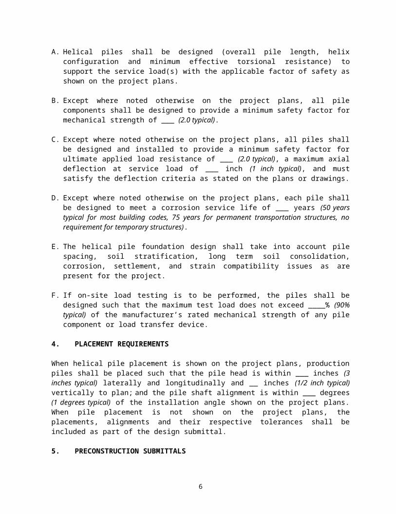
A. Helical piles shall be designed (overall pile length, helix configuration and minimum effective torsional resistance) to support the service load(s) with the applicable factor of safety as shown on the project plans.
B. Except where noted otherwise on the project plans, all pile components shall be designed to provide a minimum safety factor for mechanical strength of ___ (2.0 typical).
C. Except where noted otherwise on the project plans, all piles shall be designed and installed to provide a minimum safety factor for ultimate applied load resistance of ___ (2.0 typical), a maximum axial deflection at service load of ___ inch (1 inch typical), and must satisfy the deflection criteria as stated on the plans or drawings.
D. Except where noted otherwise on the project plans, each pile shall be designed to meet a corrosion service life of ___ years (50 years typical for most building codes, 75 years for permanent transportation structures, no requirement for temporary structures).
E. The helical pile foundation design shall take into account pile spacing, soil stratification, long term soil consolidation, corrosion, settlement, and strain compatibility issues as are present for the project.
F. If on-site load testing is to be performed, the piles shall be designed such that the maximum test load does not exceed ____% (90% typical) of the manufacturer’s rated mechanical strength of any pile component or load transfer device.
4. PLACEMENT REQUIREMENTS
4

When helical pile placement is shown on the project plans, production piles shall be placed such that the pile head is within ___ inches (3 inches typical) laterally and longitudinally and __ inches (1/2 inch typical) vertically to plan; and the pile shaft alignment is within ___ degrees (1 degrees typical) of the installation angle shown on the project plans. When pile placement is not shown on the project plans, the placements, alignments and their respective tolerances shall be included as part of the design submittal.
5. PRECONSTRUCTION SUBMITTALS
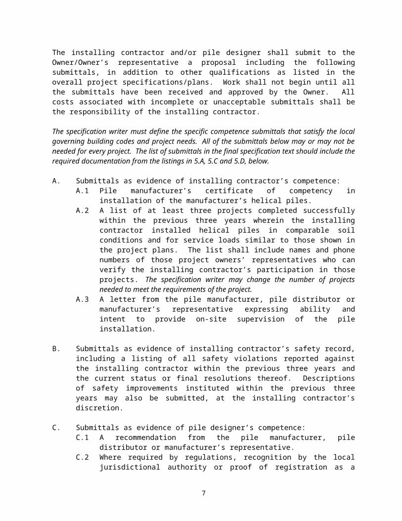
The installing contractor and/or pile designer shall submit to the Owner/Owner’s representative a proposal including the following submittals, in addition to other qualifications as listed in the overall project specifications/plans. Work shall not begin until all the submittals have been received and approved by the Owner. All costs associated with incomplete or unacceptable submittals shall be the responsibility of the installing contractor.
The specification writer must define the specific competence submittals that satisfy the local governing building codes and project needs. All of the submittals below may or may not be needed for every project. The list of submittals in the final specification text should include the required documentation from the listings in 5.A, 5.C and 5.D, below.
A. Submittals as evidence of installing contractor’s competence:A.1 Pile manufacturer’s certificate of competency in installation of the
manufacturer’s helical piles.A.2 A list of at least three projects completed successfully within the previous three
years wherein the installing contractor installed helical piles in comparable soil conditions and for service loads similar to those shown in the project plans. The list shall include names and phone numbers of those project owners’ representatives who can verify the installing contractor’s participation in those projects. The specification writer may change the number of projects needed to meet the requirements of the project.
A.3 A letter from the pile manufacturer, pile distributor or manufacturer’s representative expressing ability and intent to provide on-site supervision of the pile installation.
B. Submittals as evidence of installing contractor’s safety record, including a listing of all safety violations reported against the installing contractor within the previous three years and the current status or final resolutions thereof. Descriptions of safety improvements instituted within the previous three years may also be submitted, at the installing contractor’s discretion.
C. Submittals as evidence of pile designer’s competence:C.1 A recommendation from the pile manufacturer, pile distributor or manufacturer’s
representative.C.2 Where required by regulations, recognition by the local jurisdictional authority or
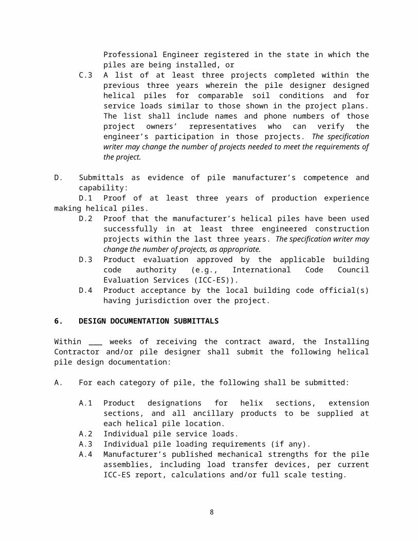
proof of registration as a Professional Engineer registered in the state in which the piles are being installed, or
C.3 A list of at least three projects completed within the previous three years wherein the pile designer designed helical piles for comparable soil conditions and for service loads similar to those shown in the project plans. The list shall include names and phone numbers of those project owners’ representatives who can verify the engineer’s participation in those projects. The specification
5
writer may change the number of projects needed to meet the requirements of the project.
D. Submittals as evidence of pile manufacturer’s competence and capability:D.1 Proof of at least three years of production experience making helical piles.D.2 Proof that the manufacturer’s helical piles have been used successfully in at
least three engineered construction projects within the last three years. The specification writer may change the number of projects, as appropriate.
D.3 Product evaluation approved by the applicable building code authority (e.g., International Code Council Evaluation Services (ICC-ES)).
D.4 Product acceptance by the local building code official(s) having jurisdiction over the project.
6. DESIGN DOCUMENTATION SUBMITTALS
Within ___ weeks of receiving the contract award, the Installing Contractor and/or pile designer shall submit the following helical pile design documentation:
A. For each category of pile, the following shall be submitted:
A.1 Product designations for helix sections, extension sections, and all ancillary products to be supplied at each helical pile location.
A.2 Individual pile service loads.A.3 Individual pile loading requirements (if any).A.4 Manufacturer’s published mechanical strengths for the pile assemblies,
including load transfer devices, per current ICC-ES report, calculations and/or full scale testing.
A.5 Calculated geotechnical capacity of piles based on geotechnical information.A.6 Minimum effective torsional resistance criteria.A.7 Maximum allowable installation torque of pile.A.8 Minimum and/or maximum embedment depth/length requirements as
appropriate for site soil profiles and site-specific minimum embedment depth/length. (Depth and length may be defined separately for inclined piles.)
A.9 Inclination angle and location tolerance requirements.
B. Drawings showing the proposed pile placements and placement tolerances (if pile placements are not depicted on the project plans). Known Rights of Way and obstructions (provided by the Owner) shall be identified to demonstrate how the piles will be installed to miss these items.
C. Proposed production quality control plan, including method and equipment to be used to measure torsional resistance during installation.
D. Procedures and acceptance criteria for any proposed performance and/or proof testing.
E. A design submittal prepared by the helical pile foundation designer which shows that the selected piles can be installed to achieve the performance requirements (Section 3) of the project plans and this specification. Typically, the Owner is responsible for defining acceptance criteria and any post-construction requirements. However, if the
6
pile designer defines the acceptance criteria for the Owner, all criteria should be outlined in the design submittal.
F. Copies of certified calibration reports for torque measuring equipment and load measuring equipment (if required) to be used on the project. The calibrations shall be performed within 12 months of the proposed starting date for helical pile installation or as recommended by the equipment manufacturer based on the proposed starting date.
7. PILE INSTALLATION
A. Before entering a construction site to begin work, the Installing Contractor shall provide proof of insurance coverage as stated in the general specifications and/or contract.
B. Installing Contractor shall furnish and install all helical piles per the project plans and pile design documentation approved by the Owner. In the event of conflict between the project plans and the approved pile design documentation, the Installing Contractor shall not begin construction on any affected items until such conflict has been resolved.
C. The Installing Contractor shall conduct construction operations in a manner to ensure the safety of persons and property in the vicinity of the work. Personnel shall comply with safety procedures that are both in accordance with OSHA standards and specified in established project safety plan.
D. The Installing Contractor or Owner shall request marking of underground utilities by an underground utility location service (as required by law) and shall avoid contact with all marked underground facilities. It is the responsibility of the Owner of site to provide to the Installing Contractor all private utility information.
E. The portion of the construction site occupied by the Installing Contractor, his equipment and his material stockpiles shall be kept reasonably clean and orderly.
F. Installation of helical piles may be observed by representatives of the Owner for quality assurance purposes. The Installing Contactor shall notify the Owner’s representative at least 24 hours prior to pile installation operations. All helical pile sections and ancillary products shall be marked as necessary to allow correlation with the pile design documentation before shipment from the manufacturer.
G. The helical pile installation technique shall be such that it is consistent with the geotechnical, logistical, environmental, and load carrying conditions of the project. The lead section shall be positioned at the location as shown on the pile design drawings. Inclined helical piles can be positioned perpendicular to the ground to assist in initial advancement into the soil before the required installation angle shall be established. After initial penetration, the required installation angle shall be established. The helical pile sections shall be engaged and advanced into the soil in a smooth, continuous manner at a rate of rotation of 5 to 25 rpm. Sufficient crowd shall be applied to uniformly advance the helical pile sections a minimum of 80% of the distance equal to the pitch of the helix plate (pitch is typically 3 inches) per revolution. The rate of rotation and magnitude of crowd shall be adjusted for different soil conditions and depths. Extension sections shall be provided to obtain the required minimum overall depth/length and minimum effective torsional resistance as shown on the project plans.
7
8. TERMINATION CRITERIA
The specified minimum overall depth/length criteria and minimum effective torsional resistance criterion must be satisfied prior to terminating the helical pile installation. In the event any helical pile fails to meet these production quality control criteria, the following pre-qualified remedies are authorized:
A. If the installation fails to meet the minimum effective torsional resistance criterion at the minimum embedment depth/length:
A.1. Continue the installation to greater depth/length in the specified bearing stratum until the effective torsional resistance criterion is met, provided that continued installation does not exceed specified maximum length (if applicable). Or
A.2. Demonstrate acceptable pile performance through load testing. Or,A.3. Replace the pile with one having a different helix configuration. The
replacement pile must not exceed any applicable maximum embedment length and either (A) be embedded to a length that places its last helix at least three times its own diameter beyond the position of the first helix of the replaced pile and meet the minimum effective torsional resistance criterion, or (B) pass load testing.
B. If the torque measured during installation reaches the helical pile’s allowable torque rating (as defined in the design submittal) prior to reaching the minimum embedment depth/length criterion, with approval from the Owner/Owner’s representative, terminate the installation then proceed with one of the following recommended actions:
B.1. Replace the pile with one having a shaft with a higher torsional strength rating. This replacement pile must be installed to satisfy the minimum embedment depth/length criterion. It must also be embedded to a depth/length that places its last helix at least three times its own diameter beyond the position of the first helix of the replaced pile without exceeding any applicable maximum embedment depth/length requirements and it must meet the minimum effective torsional resistance criterion. Or,
B.2. Replace or modify the pile with one having a different helix configuration. This replacement or modified pile must be installed to satisfy the minimum embedment depth/length criterion. It must also be embedded to a depth/length that places its last helix at least three times its own diameter beyond the position of the first helix of the replaced pile without exceeding any applicable maximum embedment depth/length requirements, and it must meet the minimum effective torsional resistance criterion. Or,
B.3. If allowed or approved by the Owner/Owner’s representative, remove and reinstall the pile at a position at least three times the diameter of the largest helix away from the initial location. Original minimum embedment depth/length and effective torsional resistance criteria must be met for the repositioned pile. This pile repositioning may require the installation of additional helical piles with service loads adjusted for these spacing changes.
C. If the installation reaches a specified maximum embedment depth/length without achieving the minimum effective torsional resistance criterion:
8
C.1. If approved by the Owner/Owner’s representative, remove and reinstall the pile at a position at least three times the diameter of the largest helix away from the initial location. Original minimum installation depth/length and effective torsional resistance criteria must be met for the repositioned pile. This pile repositioning may require the installation of additional helical piles with service loads adjusted for these spacing changes. Or,
C.2. Demonstrate acceptable pile performance through proof testing, Or C.3. Reduce the load capacity of the helical pile and install additional pile as
necessary. The reduced capacity and additional pile location shall be subject to the approval of the Owner/Owner’s representative. Or,
C.4. Replace the pile with one having a different helix configuration. This replacement pile must be embedded to a depth/length that places its last helix at least three times its own diameter beyond the position of the first helix of the replaced pile. This replacement pile must be installed to satisfy the minimum embedment depth/length criterion and it must meet the minimum effective torsional resistance criterion.
D. If a helical pile fails to meet acceptance criteria in a performance or proof test:
D.1. Install the pile to a greater depth/length and installation torque and re-test provided that the maximum embedment depth/length criterion (if applicable) is not exceeded. Or
D.2. Replace the pile with one having more and/or larger helix plates. It must be embedded to a depth/length that places its last helix at least three times its own diameter beyond the position of the first helix of the replaced pile without exceeding any applicable maximum embedment depth/length requirements. This replacement pile must be re-tested. Or,
D.3 If approved by the Owner’s representative, de-rate the load capacity of the helical pile and install additional piles. Additional piles must be installed at positions that are at least three times the diameter of the largest helix away from any other pile locations and are approved by the Owner’s representative. Piles installed in cohesive soils shall not be spaced closer than four helix diameters.
Load testing to qualify a helical pile under any of the remedial actions outlined in Section 8 shall not be used to satisfy load testing frequency requirements shown in the project plans or the approved design submittals.
If a helical pile fails a production quality control criterion for any other reason (including damage during installation), any proposed remedy must be approved by the Owner/Owner’s representative prior to implementation.
9. INSTALLATION RECORD SUBMITTALS
The installing contractor shall provide the Owner, or his authorized representative, copies of individual helical pile installation records within 24 hours after each installation is completed. Formal copies shall be submitted (insert time frequency). These installation records shall include, but are not limited to, the following information:
A. Date and time of installation.B. Installation equipment type and operator name.C. Plan location of helical pile.
9
D. Pile reveal.E. As-built helical pile type and configuration.F. Total length of installed pile.G. As-built installation angle of pile.H. Torque measurements at 1 foot intervals over the for the last ___ feet (5 to 10 feet
typical but not less than 3 times the diameter of the largest helix plate) of installed length, at a minimum.
I. Effective torsional resistance and calculated geotechnical capacity based on effective torsional resistance and/or as derived from the pre-production test program.
J. Comments pertaining to interruptions, obstructions, or other relevant information.
10. PILE TESTING
If pile testing is required, the Installing Contractor shall furnish all labor, equipment and pre-production helical piles necessary to accomplish the testing as shown in the previously submitted and approved pile design submittals. The installing contractor shall apply the specified loads for the specified durations and record the specified data, for the specified number of piles. No deviations from the test plan(s) will be allowed without explicit approval in writing from the Owner/Owner’s representative. Pile testing shall be in accordance with the load-testing procedures and performance requirements deemed suitable for the application by the Owner/Owner’s representative, or pile designer.
Installing Contractor shall provide the Owner, or Owner’s representative, copies of field test data or reports within 24 hours after completion of each load test. Formal test reports shall be submitted within (insert amount of time) following test completion. Formal test reports shall include, but are not limited to, the following information:
A. Name of project and installing contractor.B. Name of installing contractor’s supervisor during installation.C. Name of third party test agency, if any.D. Type of test (pre-production or production test)E. Date, time, and duration of test.F. Unique identifier and location of helical pile tested.G. Test criteria (performance or proof).H. Description of calibrated testing equipment and test set-up.I. Testing equipment calibration data.J. Actual helical pile type and configuration.K. Reaction frame/pile installation and verification data, as required by Owner or Pile
Designer. -L. Steps and duration of each load increment.M. Incremental and cumulative pile-head movement at each load step.N. Signatures as required by local jurisdiction
10

11. CLEANUP
Within (insert time period) of completion of the work, the installing contractor shall remove any and all material, equipment, tools, building materials, concrete forms, debris, or other items belonging to the Installing Contractor or used under the Installing Contractor’s direction.
12. MEASUREMENT AND PAYMENT
Helical piles can be paid for in different ways, and the following items should be defined by the Owner/Owner’s Representative:
QUANTITY DESCRIPTION UNIT1 Mobilization/Demobilization Lump sum
As required Helical Trial Piles Per pile
As required Obstructions (Pay items as defined in Contract)
Per hour or Force Account
As required Helical Pile Installation Per foot (meter) or per pile
As required Production Load Test Program Lump sum or per test
11