single level of tiebacks - soil pressure
TRANSCRIPT
Terracon Consultants, Inc. 21905 – 64 th Avenue West, Suite 100 Mount lake Ter race, Washington 98043
P [425] 771 3304 F [425] 771 3549 terracon.com
April 6, 2021
Malcolm Drilling Company
8701 S 192nd St
Kent, WA 98031
Attn: Adam Running, Project Manager E: [email protected]
P: (253) 395-3300
Re: Response to SDCI Cycle 3 Structural Corrections
SDCI #6693268-CN
Seattle, Washington 98109
Terracon Project Number 81195208
Dear Adam:
As requested, Terracon Consultants, Inc. (Terracon) is providing responses to the cycle 3
structural corrections by Seattle Department of Construction and Inspection (SDCI) on the
shoring design for 701 Dexter Ave. North, Seattle, Washington. Correction Notice #3 is dated
December 29, 2020. The structural reviewer is Ben Enfield. The following are the corrections that
apply to the shoring design and our responses.
Correction 6: Single level of tiebacks - soil pressure
3/SH4.0 - The loading diagrams from the geotechnical engineer are only for multi-level tiebacks,
but NP21+ are single level tiebacks. Clarify the application of the multi-level tieback loading with
the single level of tiebacks.
Response to Correction 6: The geotechnical engineer has provided a loading diagram for single
row of tiebacks. The loading diagram is now included on Sheet SH1.0 of the shoring design
drawings and is the same that Terracon used in their design.
Correction 7: North wall - force at west edge of existing building
SH3.0 NP-14 - At the west edge of the existing building there is a discontinuity in force design of
the piles. NP-13 is designed for 22H, and NP-14 is designed for 28h+surcharge. The previous
iteration of this wall's design only had about 10' of retained soil below the existing building, so
28h+surcharge was similar to the adjacent 22H load. In this new design there is about 20' below
the adjacent building, so the 28h+surcharge for the lower anchor appears to be decently lower
than the 22H on the adjacent pile. Coordinate with the geotechnical engineer the force that NP-14
and NP-15 are to be designed for.
Response to SDCI Cycle 3 Structural Corrections–701 Dexter Ave N Malcolm Drilling Company ■ Kent, WA April 6, 2021 ■ Terracon Project Number 81195208
Responsive ■ Resourceful ■ Reliable 2
Response to Correction 7: Terracon has coordinated with the geotechnical engineer of record,
Hart Crowser, and the tieback loading is correct as presented with the exception of the increased
tieback loads in response to correction 8.
Correction 8: North wall - existing building interior footing surcharge loading
SH3.0 NP-X - The new design has about 10 additional feet of depth, and thus interior footings
may add pressure to the shoring wall. Verify that footings within h of the shoring have been
accounted for in the loads on the shoring, including the orthogonal basement walls loading up
strip footings at grids 5.3 and 1.1.
Response to Correction 8. Where the column footings are located within 1H:1V
(horizontal:vertical) slope of the shoring wall, the column footing loads are now included in the
building surcharge pressures. Where the orthogonal basement wall is adjacent to the shoring
wall, the footing loads are now included in the building surcharge pressure. The soldier pile sizes
did not change; however, the tieback loads increased. Calculations are attached for the revised
north shoring wall design.
The revisions to the drawings in response to the review comments are clouded. In addition, the
as built SCL Vault information was provided to Terracon. Based on the SCL vault as built
information, the tieback elevations required lowering to provide clearance below the vault.
Lowering the tieback increased the tieback loads. The calculations for the south shoring wall
revision in response to the SCL as built information are attached to this letter. The shoring
drawing release in response to the cycle 3 comments and the SCL Vault as built information is
revision 3, dated 4-6-2021.
If you have any questions or comments regarding our comment responses, please contact us.
Sincerely,
Terracon Consultants, Inc.
Richard D. Luark, P.E. Trey Benson, EIT
Principal Field Engineer
Attachments: North Shoring Wall Calculations in Response to the Cycle 3 Corrections Revised South Shoring Wall Calculations at As Built Vault Location
701 Dexter Soldier Pile and Tieback Shoring – Revision 3 1 14 81195208 4/6/2021 R. Luark T. Benson
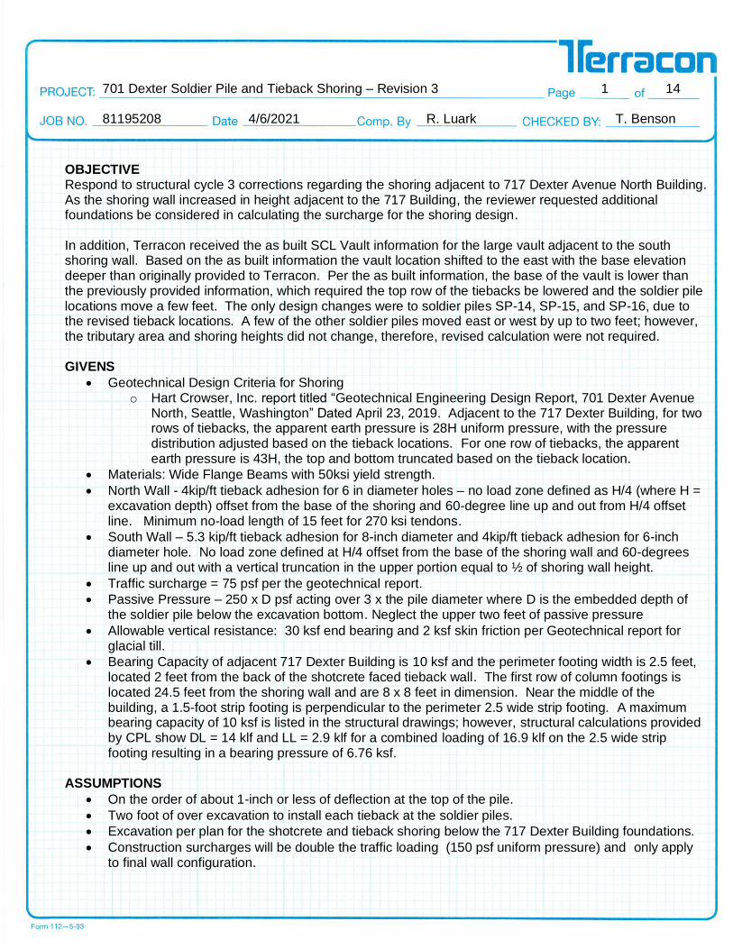
OBJECTIVE Respond to structural cycle 3 corrections regarding the shoring adjacent to 717 Dexter Avenue North Building. As the shoring wall increased in height adjacent to the 717 Building, the reviewer requested additional foundations be considered in calculating the surcharge for the shoring design. In addition, Terracon received the as built SCL Vault information for the large vault adjacent to the south shoring wall. Based on the as built information the vault location shifted to the east with the base elevation deeper than originally provided to Terracon. Per the as built information, the base of the vault is lower than the previously provided information, which required the top row of the tiebacks be lowered and the soldier pile locations move a few feet. The only design changes were to soldier piles SP-14, SP-15, and SP-16, due to the revised tieback locations. A few of the other soldier piles moved east or west by up to two feet; however, the tributary area and shoring heights did not change, therefore, revised calculation were not required. GIVENS
• Geotechnical Design Criteria for Shoring o Hart Crowser, Inc. report titled “Geotechnical Engineering Design Report, 701 Dexter Avenue
North, Seattle, Washington” Dated April 23, 2019. Adjacent to the 717 Dexter Building, for two rows of tiebacks, the apparent earth pressure is 28H uniform pressure, with the pressure distribution adjusted based on the tieback locations. For one row of tiebacks, the apparent earth pressure is 43H, the top and bottom truncated based on the tieback location.
• Materials: Wide Flange Beams with 50ksi yield strength.
• North Wall - 4kip/ft tieback adhesion for 6 in diameter holes – no load zone defined as H/4 (where H = excavation depth) offset from the base of the shoring and 60-degree line up and out from H/4 offset line. Minimum no-load length of 15 feet for 270 ksi tendons.
• South Wall – 5.3 kip/ft tieback adhesion for 8-inch diameter and 4kip/ft tieback adhesion for 6-inch diameter hole. No load zone defined at H/4 offset from the base of the shoring wall and 60-degrees line up and out with a vertical truncation in the upper portion equal to ½ of shoring wall height.
• Traffic surcharge = 75 psf per the geotechnical report.
• Passive Pressure – 250 x D psf acting over 3 x the pile diameter where D is the embedded depth of the soldier pile below the excavation bottom. Neglect the upper two feet of passive pressure
• Allowable vertical resistance: 30 ksf end bearing and 2 ksf skin friction per Geotechnical report for glacial till.
• Bearing Capacity of adjacent 717 Dexter Building is 10 ksf and the perimeter footing width is 2.5 feet, located 2 feet from the back of the shotcrete faced tieback wall. The first row of column footings is located 24.5 feet from the shoring wall and are 8 x 8 feet in dimension. Near the middle of the building, a 1.5-foot strip footing is perpendicular to the perimeter 2.5 wide strip footing. A maximum bearing capacity of 10 ksf is listed in the structural drawings; however, structural calculations provided by CPL show DL = 14 klf and LL = 2.9 klf for a combined loading of 16.9 klf on the 2.5 wide strip footing resulting in a bearing pressure of 6.76 ksf.
ASSUMPTIONS
• On the order of about 1-inch or less of deflection at the top of the pile.
• Two foot of over excavation to install each tieback at the soldier piles.
• Excavation per plan for the shotcrete and tieback shoring below the 717 Dexter Building foundations.
• Construction surcharges will be double the traffic loading (150 psf uniform pressure) and only apply to final wall configuration.
701 Dexter Soldier Pile and Tieback Shoring – Revision 3 2 14 81195208 4/6/2021 R. Luark T. Benson
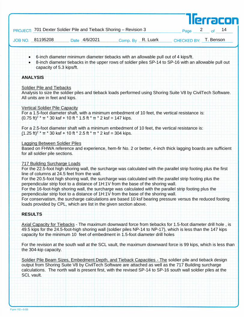
• 6-inch diameter minimum diameter tiebacks with an allowable pull out of 4 kips/ft.
• 8-inch diameter tiebacks in the upper rows of soldier piles SP-14 to SP-16 with an allowable pull out capacity of 5.3 kips/ft.
ANALYSIS Soldier Pile and Tiebacks Analysis to size the soldier piles and tieback loads performed using Shoring Suite V8 by CivilTech Software. All units are in feet and kips. Vertical Soldier Pile Capacity For a 1.5-foot diameter shaft, with a minimum embedment of 10 feet, the vertical resistance is: (0.75 ft)2 * π * 30 ksf + 10 ft * 1.5 ft * π * 2 ksf = 147 kips. For a 2.5-foot diameter shaft with a minimum embedment of 10 feet, the vertical resistance is: (1.25 ft)2 * π * 30 ksf + 10 ft * 2.5 ft * π * 2 ksf = 304 kips. Lagging Between Soldier Piles Based on FHWA reference and experience, hem-fir No. 2 or better, 4-inch thick lagging boards are sufficient for all soldier pile sections. 717 Building Surcharge Loads For the 22.5-foot high shoring wall, the surcharge was calculated with the parallel strip footing plus the first line of columns at 24.5 feet from the wall. For the 20.5-foot high shoring wall, the surcharge was calculated with the parallel strip footing plus the perpendicular strip foot to a distance of 1H:1V from the base of the shoring wall. For the 16-foot-high shoring wall, the surcharge was calculated with the parallel strip footing plus the perpendicular strip foot to a distance of 1H:1V from the base of the shoring wall. For conservatism, the surcharge calculations are based 10 ksf bearing pressure versus the reduced footing loads provided by CPL, which are list in the given section above. RESULTS Axial Capacity for Tiebacks - The maximum downward force from tiebacks for 1.5-foot diameter drill hole , is 49.5 kips for the 24.5-foot-high shoring wall (soldier piles NP-14 to NP-17), which is less than the 147 kips capacity for the minimum 10 feet of embedment in 1.5-foot diameter drill holes For the revision at the south wall at the SCL vault, the maximum downward force is 99 kips, which is less than the 304-kip capacity.
Soldier Pile Beam Sizes, Embedment Depth, and Tieback Capacities - The soldier pile and tieback design output from Shoring Suite V8 by CivilTech Software are attached as well as the 717 Building surcharge calculations. The north wall is present first, with the revised SP-14 to SP-16 south wall soldier piles at the SCL vault.
701 Dexter Soldier Pile and Tieback Shoring – Revision 3 3 14 81195208 4/6/2021 R. Luark T. Benson
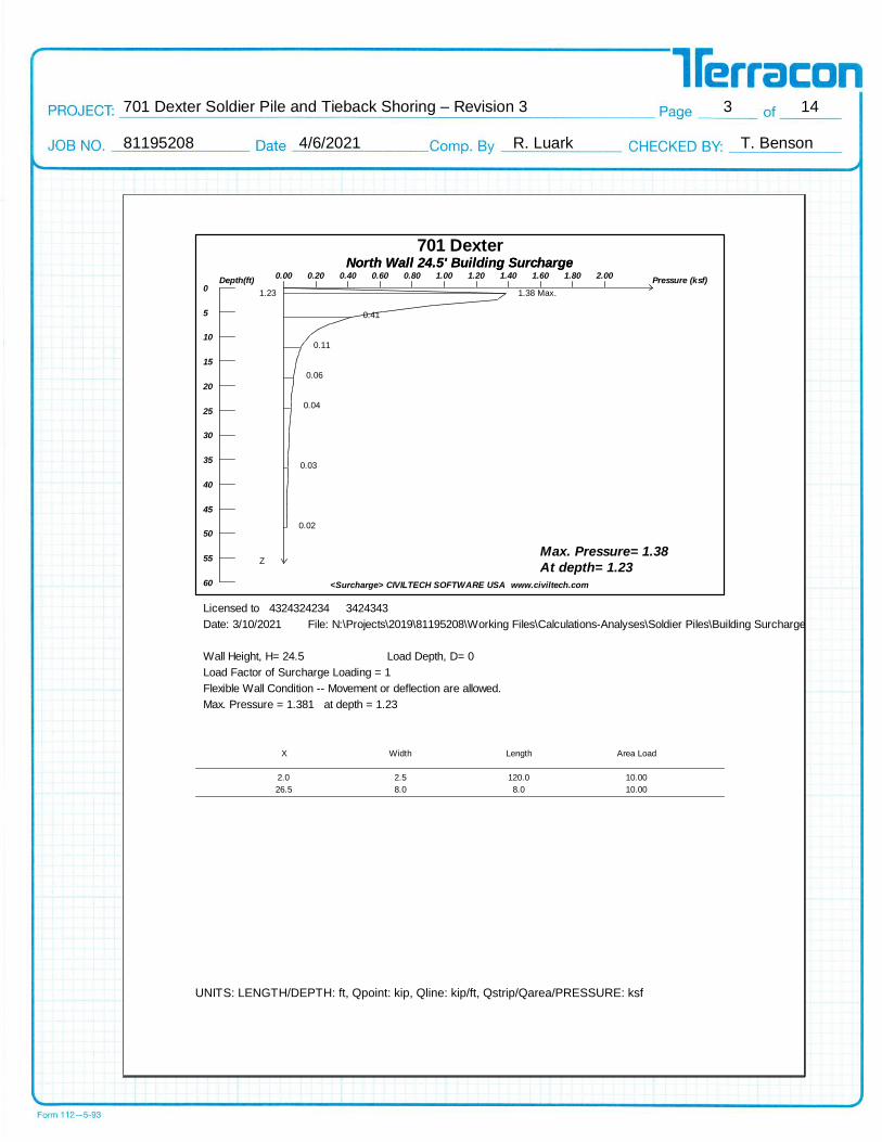
701 DexterNorth Wall 24.5' Building SurchargeNorth Wall 24.5' Building Surcharge
<Surcharge> CIVILTECH SOFTWARE USA www.civiltech.com
Pressure (ksf)0.00 0.20 0.40 0.60 0.80 1.00 1.20 1.40 1.60 1.80 2.00
Depth(ft)0
5
10
15
20
25
30
35
40
45
50
55
60
Max. Pressure= 1.38
At depth= 1.23Z
0.41
0.11
0.06
0.04
0.03
0.02
1.23 1.38 Max.
Licensed to 4324324234 3424343
Date: 3/10/2021 File: N:\Projects\2019\81195208\Working Files\Calculations-Analyses\Soldier Piles\Building Surcharge\R3\24.5 ft north wall - strip plus column.lp8
Wall Height, H= 24.5 Load Depth, D= 0
Load Factor of Surcharge Loading = 1
Flexible Wall Condition -- Movement or deflection are allowed.
Max. Pressure = 1.381 at depth = 1.23
X Width Length Area Load
2.0 2.5 120.0 10.00
26.5 8.0 8.0 10.00
UNITS: LENGTH/DEPTH: ft, Qpoint: kip, Qline: kip/ft, Qstrip/Qarea/PRESSURE: ksf
701 Dexter Soldier Pile and Tieback Shoring – Revision 3 4 14 81195208 4/6/2021 R. Luark T. Benson
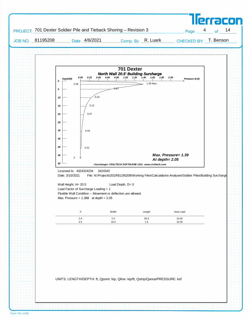
701 DexterNorth Wall 20.5' Building SurchargeNorth Wall 20.5' Building Surcharge
<Surcharge> CIVILTECH SOFTWARE USA www.civiltech.com
Pressure (ksf)0.00 0.20 0.40 0.60 0.80 1.00 1.20 1.40 1.60 1.80 2.00
Depth(ft)0
5
10
15
20
25
30
35
40
45
50
Max. Pressure= 1.39
At depth= 2.05Z
0.67
0.24
0.12
0.07
0.03
0.01
2.05 1.39 Max.
Licensed to 4324324234 3424343
Date: 3/10/2021 File: N:\Projects\2019\81195208\Working Files\Calculations-Analyses\Soldier Piles\Building Surcharge\R3\20.5 ft north wall - strip plus perpindicular strip.lp8
Wall Height, H= 20.5 Load Depth, D= 0
Load Factor of Surcharge Loading = 1
Flexible Wall Condition -- Movement or deflection are allowed.
Max. Pressure = 1.388 at depth = 2.05
X Width Length Area Load
2.0 2.5 50.0 10.00
4.5 16.0 1.5 10.00
UNITS: LENGTH/DEPTH: ft, Qpoint: kip, Qline: kip/ft, Qstrip/Qarea/PRESSURE: ksf

701 Dexter Soldier Pile and Tieback Shoring – Revision 3 5 14 81195208 4/6/2021 R. Luark T. Benson
701 DexterNorth Wall 16' Building SurchargeNorth Wall 16' Building Surcharge
<Surcharge> CIVILTECH SOFTWARE USA www.civiltech.com
Pressure (ksf)0.00 0.20 0.40 0.60 0.80 1.00 1.20 1.40 1.60 1.80 2.00
Depth(ft)0
5
10
15
20
25
30
35
40
Max. Pressure= 1.39
At depth= 1.60Z
0.88
0.32
0.15
0.09
0.03
0.02
1.60 1.39 Max.
Licensed to 4324324234 3424343
Date: 3/10/2021 File: N:\Projects\2019\81195208\Working Files\Calculations-Analyses\Soldier Piles\Building Surcharge\R3\16 ft north wall - strip plus perpindicular Footing.lp8
Wall Height, H= 16 Load Depth, D= 0
Load Factor of Surcharge Loading = 1
Flexible Wall Condition -- Movement or deflection are allowed.
Max. Pressure = 1.390 at depth = 1.60
X Width Length Area Load
2.0 2.5 50.0 10.00
4.5 11.5 1.5 10.00
UNITS: LENGTH/DEPTH: ft, Qpoint: kip, Qline: kip/ft, Qstrip/Qarea/PRESSURE: ksf
701 Dexter Soldier Pile and Tieback Shoring – Revision 3 6 14 81195208 4/6/2021 R. Luark T. Benson
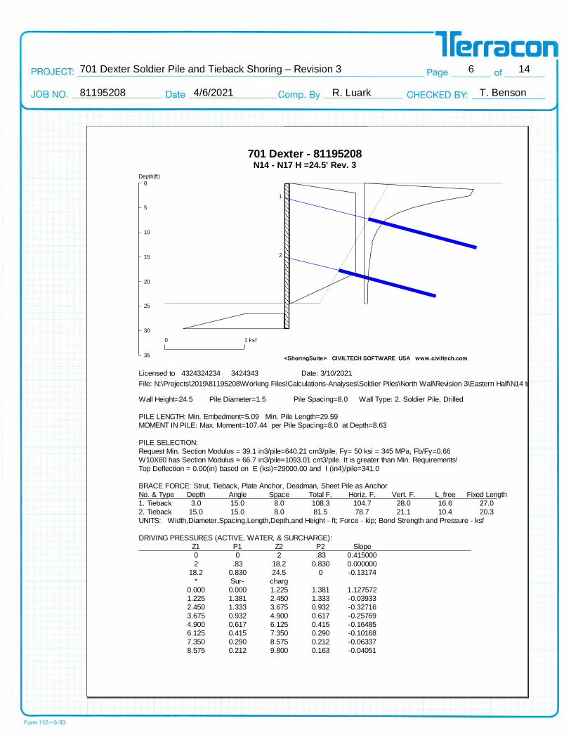
701 Dexter - 81195208N14 - N17 H =24.5' Rev. 3
<ShoringSuite> CIVILTECH SOFTWARE USA www.civiltech.com
1
2
Depth(ft)
0
5
10
15
20
25
30
35
0 1 ksf
Licensed to 4324324234 3424343 Date: 3/10/2021
File: N:\Projects\2019\81195208\Working Files\Calculations-Analyses\Soldier Piles\North Wall\Revision 3\Eastern Half\N14 to N17 h = 24.5'.sh8
Wall Height=24.5 Pile Diameter=1.5 Pile Spacing=8.0 Wall Type: 2. Soldier Pile, Drilled
PILE LENGTH: Min. Embedment=5.09 Min. Pile Length=29.59
MOMENT IN PILE: Max. Moment=107.44 per Pile Spacing=8.0 at Depth=8.63
PILE SELECTION:
Request Min. Section Modulus = 39.1 in3/pile=640.21 cm3/pile, Fy= 50 ksi = 345 MPa, Fb/Fy=0.66
W10X60 has Section Modulus = 66.7 in3/pile=1093.01 cm3/pile. It is greater than Min. Requirements!
Top Deflection = 0.00(in) based on E (ksi)=29000.00 and I (in4)/pile=341.0
BRACE FORCE: Strut, Tieback, Plate Anchor, Deadman, Sheet Pile as Anchor
No. & Type Depth Angle Space Total F. Horiz. F. Vert. F. L_free Fixed Length
1. Tieback 3.0 15.0 8.0 108.3 104.7 28.0 16.6 27.0
2. Tieback 15.0 15.0 8.0 81.5 78.7 21.1 10.4 20.3
UNITS: Width,Diameter,Spacing,Length,Depth,and Height - ft; Force - kip; Bond Strength and Pressure - ksf
DRIVING PRESSURES (ACTIVE, WATER, & SURCHARGE):
Z1 P1 Z2 P2 Slope
0 0 2 .83 0.415000
2 .83 18.2 0.830 0.000000
18.2 0.830 24.5 0 -0.13174
* Sur- charg
0.000 0.000 1.225 1.381 1.127572
1.225 1.381 2.450 1.333 -0.03933
2.450 1.333 3.675 0.932 -0.32716
3.675 0.932 4.900 0.617 -0.25769
4.900 0.617 6.125 0.415 -0.16485
6.125 0.415 7.350 0.290 -0.10168
7.350 0.290 8.575 0.212 -0.06337
8.575 0.212 9.800 0.163 -0.04051
701 Dexter Soldier Pile and Tieback Shoring – Revision 3 7 14 81195208 4/6/2021 R. Luark T. Benson
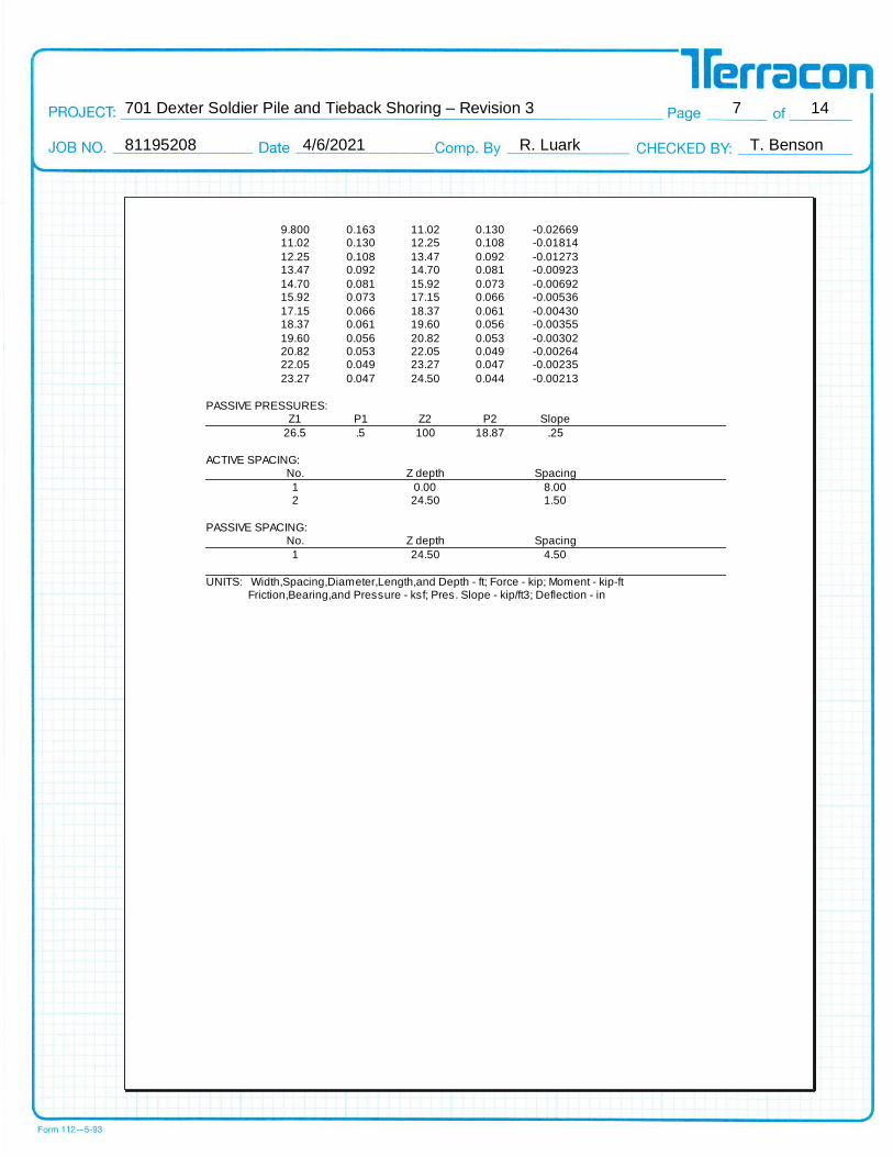
9.800 0.163 11.02 0.130 -0.0266911.02 0.130 12.25 0.108 -0.01814
12.25 0.108 13.47 0.092 -0.0127313.47 0.092 14.70 0.081 -0.00923
14.70 0.081 15.92 0.073 -0.0069215.92 0.073 17.15 0.066 -0.00536
17.15 0.066 18.37 0.061 -0.0043018.37 0.061 19.60 0.056 -0.00355
19.60 0.056 20.82 0.053 -0.0030220.82 0.053 22.05 0.049 -0.0026422.05 0.049 23.27 0.047 -0.00235
23.27 0.047 24.50 0.044 -0.00213
PASSIVE PRESSURES: Z1 P1 Z2 P2 Slope
26.5 .5 100 18.87 .25
ACTIVE SPACING:No. Z depth Spacing
1 0.00 8.002 24.50 1.50
PASSIVE SPACING:No. Z depth Spacing
1 24.50 4.50
UNITS: Width,Spacing,Diameter,Length,and Depth - ft; Force - kip; Moment - kip-ft Friction,Bearing,and Pressure - ksf; Pres. Slope - kip/ft3; Deflection - in
701 Dexter Soldier Pile and Tieback Shoring – Revision 3 8 14 81195208 4/6/2021 R. Luark T. Benson
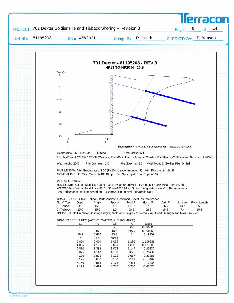
701 Dexter - 81195208 - REV 3NP18 TO NP20 H =20.5'
<ShoringSuite> CIVILTECH SOFTWARE USA www.civiltech.com
1
2
Depth(ft)
0
5
10
15
20
25
0 1 ksf
Licensed to 4324324234 3424343 Date: 3/10/2021
File: N:\Projects\2019\81195208\Working Files\Calculations-Analyses\Soldier Piles\North Wall\Revision 3\Eastern Half\N18 to N20 H = 20.5'.sh8
Wall Height=20.5 Pile Diameter=1.5 Pile Spacing=8.0 Wall Type: 2. Soldier Pile, Drilled
PILE LENGTH: Min. Embedment=3.79 (5~10ft is recommended!!!) Min. Pile Length=24.29
MOMENT IN PILE: Max. Moment=100.62 per Pile Spacing=8.0 at Depth=8.57
PILE SELECTION:
Request Min. Section Modulus = 36.6 in3/pile=599.60 cm3/pile, Fy= 50 ksi = 345 MPa, Fb/Fy=0.66
W10X60 has Section Modulus = 66.7 in3/pile=1093.01 cm3/pile. It is greater than Min. Requirements!
Top Deflection = 0.00(in) based on E (ksi)=29000.00 and I (in4)/pile=341.0
BRACE FORCE: Strut, Tieback, Plate Anchor, Deadman, Sheet Pile as Anchor
No. & Type Depth Angle Space Total F. Horiz. F. Vert. F. L_free Fixed Length
1. Tieback 3.0 15.0 8.0 101.3 97.8 26.2 13.7 25.3
2. Tieback 15.0 15.0 8.0 60.9 58.9 15.8 7.4 15.2
UNITS: Width,Diameter,Spacing,Length,Depth,and Height - ft; Force - kip; Bond Strength and Pressure - ksf
DRIVING PRESSURES (ACTIVE, WATER, & SURCHARGE):
Z1 P1 Z2 P2 Slope
0 0 2 .67 0.335000
2 .67 16.8 0.670 0.000000
16.8 0.670 20.5 0 -0.18108
* Sur- charg
0.000 0.000 1.025 1.196 1.166931
1.025 1.196 2.050 1.388 0.187533
2.050 1.388 3.075 1.147 -0.23539
3.075 1.147 4.100 0.876 -0.26437
4.100 0.876 5.125 0.667 -0.20385
5.125 0.667 6.150 0.519 -0.14492
6.150 0.519 7.175 0.414 -0.10236
7.175 0.414 8.200 0.338 -0.07373

701 Dexter Soldier Pile and Tieback Shoring – Revision 3 9 14 81195208 4/6/2021 R. Luark T. Benson
8.200 0.338 9.225 0.282 -0.054639.225 0.282 10.25 0.239 -0.04168
10.25 0.239 11.27 0.206 -0.0326911.27 0.206 12.30 0.179 -0.02625
12.30 0.179 13.32 0.157 -0.0215113.32 0.157 14.35 0.138 -0.01792
14.35 0.138 15.37 0.123 -0.0151315.37 0.123 16.40 0.110 -0.01292
16.40 0.110 17.42 0.098 -0.0111317.42 0.098 18.45 0.088 -0.0096618.45 0.088 19.47 0.080 -0.00844
19.47 0.080 20.50 0.072 -0.00740
PASSIVE PRESSURES: Z1 P1 Z2 P2 Slope
22.5 .5 100 19.87 .25
ACTIVE SPACING:No. Z depth Spacing
1 0.00 8.002 20.50 1.50
PASSIVE SPACING:No. Z depth Spacing
1 20.50 4.50
UNITS: Width,Spacing,Diameter,Length,and Depth - ft; Force - kip; Moment - kip-ft Friction,Bearing,and Pressure - ksf; Pres. Slope - kip/ft3; Deflection - in
701 Dexter Soldier Pile and Tieback Shoring – Revision 3 10 14 81195208 4/6/2021 R. Luark T. Benson
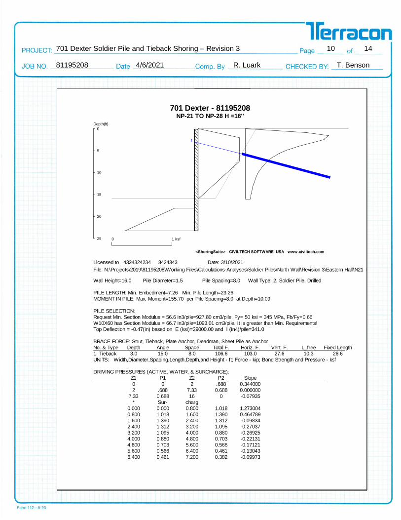
701 Dexter - 81195208NP-21 TO NP-28 H =16''
<ShoringSuite> CIVILTECH SOFTWARE USA www.civiltech.com
1
Depth(ft)
0
5
10
15
20
25 0 1 ksf
Licensed to 4324324234 3424343 Date: 3/10/2021
File: N:\Projects\2019\81195208\Working Files\Calculations-Analyses\Soldier Piles\North Wall\Revision 3\Eastern Half\N21 to N28 H = 16'.sh8
Wall Height=16.0 Pile Diameter=1.5 Pile Spacing=8.0 Wall Type: 2. Soldier Pile, Drilled
PILE LENGTH: Min. Embedment=7.26 Min. Pile Length=23.26
MOMENT IN PILE: Max. Moment=155.70 per Pile Spacing=8.0 at Depth=10.09
PILE SELECTION:
Request Min. Section Modulus = 56.6 in3/pile=927.80 cm3/pile, Fy= 50 ksi = 345 MPa, Fb/Fy=0.66
W10X60 has Section Modulus = 66.7 in3/pile=1093.01 cm3/pile. It is greater than Min. Requirements!
Top Deflection = -0.47(in) based on E (ksi)=29000.00 and I (in4)/pile=341.0
BRACE FORCE: Strut, Tieback, Plate Anchor, Deadman, Sheet Pile as Anchor
No. & Type Depth Angle Space Total F. Horiz. F. Vert. F. L_free Fixed Length
1. Tieback 3.0 15.0 8.0 106.6 103.0 27.6 10.3 26.6
UNITS: Width,Diameter,Spacing,Length,Depth,and Height - ft; Force - kip; Bond Strength and Pressure - ksf
DRIVING PRESSURES (ACTIVE, WATER, & SURCHARGE):
Z1 P1 Z2 P2 Slope
0 0 2 .688 0.344000
2 .688 7.33 0.688 0.000000
7.33 0.688 16 0 -0.07935
* Sur- charg
0.000 0.000 0.800 1.018 1.273004
0.800 1.018 1.600 1.390 0.464789
1.600 1.390 2.400 1.312 -0.09834
2.400 1.312 3.200 1.095 -0.27037
3.200 1.095 4.000 0.880 -0.26925
4.000 0.880 4.800 0.703 -0.22131
4.800 0.703 5.600 0.566 -0.17121
5.600 0.566 6.400 0.461 -0.13043
6.400 0.461 7.200 0.382 -0.09973
701 Dexter Soldier Pile and Tieback Shoring – Revision 3 11 14 81195208 4/6/2021 R. Luark T. Benson
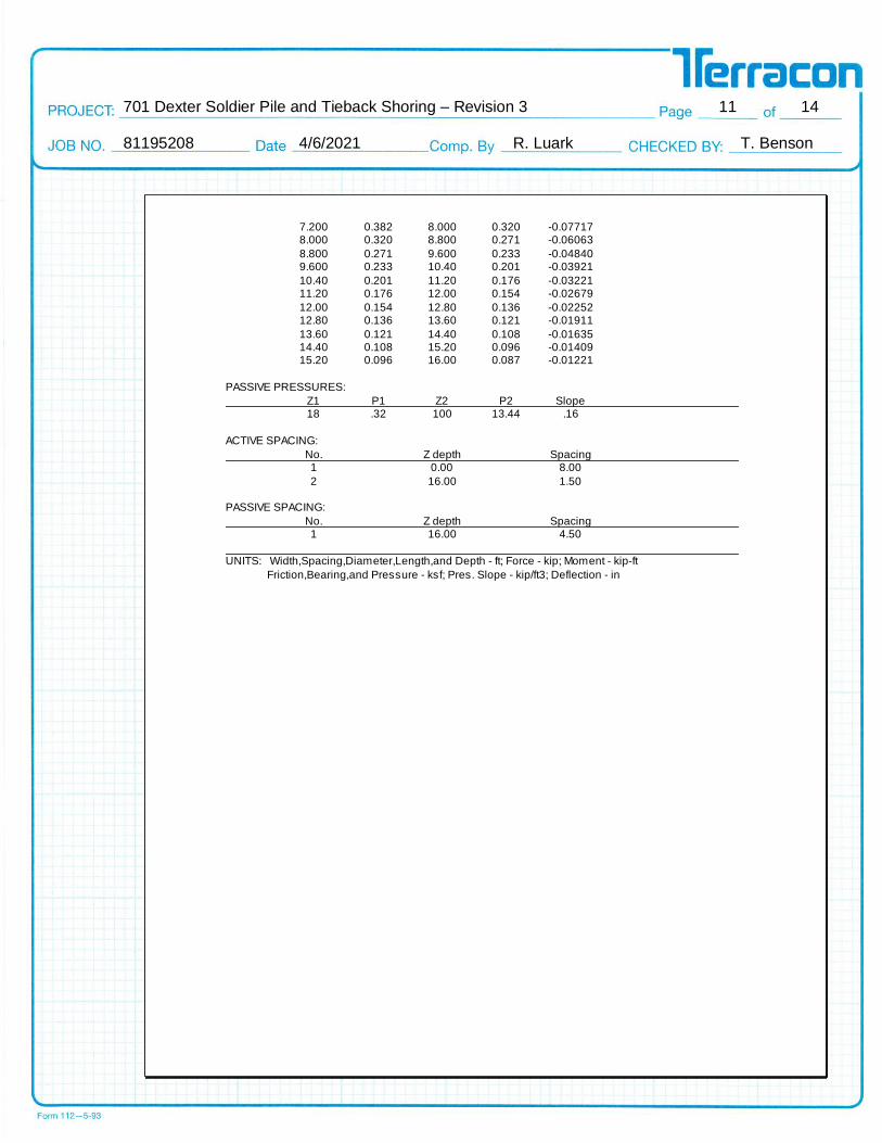
7.200 0.382 8.000 0.320 -0.077178.000 0.320 8.800 0.271 -0.06063
8.800 0.271 9.600 0.233 -0.048409.600 0.233 10.40 0.201 -0.03921
10.40 0.201 11.20 0.176 -0.0322111.20 0.176 12.00 0.154 -0.02679
12.00 0.154 12.80 0.136 -0.0225212.80 0.136 13.60 0.121 -0.01911
13.60 0.121 14.40 0.108 -0.0163514.40 0.108 15.20 0.096 -0.0140915.20 0.096 16.00 0.087 -0.01221
PASSIVE PRESSURES:
Z1 P1 Z2 P2 Slope18 .32 100 13.44 .16
ACTIVE SPACING:
No. Z depth Spacing1 0.00 8.00
2 16.00 1.50 PASSIVE SPACING:
No. Z depth Spacing1 16.00 4.50
UNITS: Width,Spacing,Diameter,Length,and Depth - ft; Force - kip; Moment - kip-ft
Friction,Bearing,and Pressure - ksf; Pres. Slope - kip/ft3; Deflection - in
701 Dexter Soldier Pile and Tieback Shoring – Revision 3 12 14 81195208 4/6/2021 R. Luark T. Benson
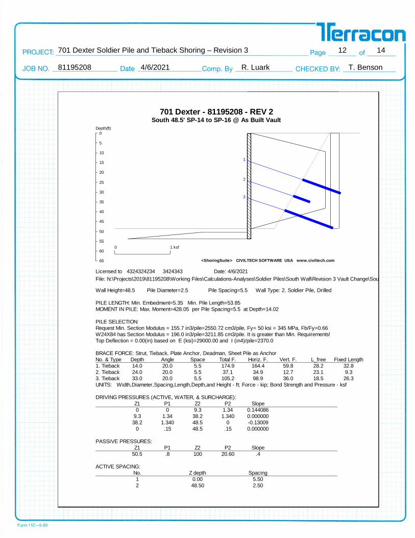
701 Dexter - 81195208 - REV 2South 48.5' SP-14 to SP-16 @ As Built Vault
<ShoringSuite> CIVILTECH SOFTWARE USA www.civiltech.com
1
2
3
Depth(ft)
0
5
10
15
20
25
30
35
40
45
50
55
60
65
0 1 ksf
Licensed to 4324324234 3424343 Date: 4/6/2021
File: N:\Projects\2019\81195208\Working Files\Calculations-Analyses\Soldier Piles\South Wall\Revision 3 Vault Change\South 48.5 ft SP-14 to SP-16 @ Electical Vault REV3.sh8
Wall Height=48.5 Pile Diameter=2.5 Pile Spacing=5.5 Wall Type: 2. Soldier Pile, Drilled
PILE LENGTH: Min. Embedment=5.35 Min. Pile Length=53.85
MOMENT IN PILE: Max. Moment=428.05 per Pile Spacing=5.5 at Depth=14.02
PILE SELECTION:
Request Min. Section Modulus = 155.7 in3/pile=2550.72 cm3/pile, Fy= 50 ksi = 345 MPa, Fb/Fy=0.66
W24X84 has Section Modulus = 196.0 in3/pile=3211.85 cm3/pile. It is greater than Min. Requirements!
Top Deflection = 0.00(in) based on E (ksi)=29000.00 and I (in4)/pile=2370.0
BRACE FORCE: Strut, Tieback, Plate Anchor, Deadman, Sheet Pile as Anchor
No. & Type Depth Angle Space Total F. Horiz. F. Vert. F. L_free Fixed Length
1. Tieback 14.0 20.0 5.5 174.9 164.4 59.8 28.2 32.8
2. Tieback 24.0 20.0 5.5 37.1 34.9 12.7 23.1 9.3
3. Tieback 33.0 20.0 5.5 105.2 98.9 36.0 18.5 26.3
UNITS: Width,Diameter,Spacing,Length,Depth,and Height - ft; Force - kip; Bond Strength and Pressure - ksf
DRIVING PRESSURES (ACTIVE, WATER, & SURCHARGE):
Z1 P1 Z2 P2 Slope
0 0 9.3 1.34 0.144086
9.3 1.34 38.2 1.340 0.000000
38.2 1.340 48.5 0 -0.13009
0 .15 48.5 .15 0.000000
PASSIVE PRESSURES:
Z1 P1 Z2 P2 Slope
50.5 .8 100 20.60 .4
ACTIVE SPACING:
No. Z depth Spacing
1 0.00 5.50
2 48.50 2.50
701 Dexter Soldier Pile and Tieback Shoring – Revision 3 13 14 81195208 4/6/2021 R. Luark T. Benson
PASSIVE SPACING:No. Z depth Spacing
1 48.50 5.50
UNITS: Width,Spacing,Diameter,Length,and Depth - ft; Force - kip; Moment - kip-ft Friction,Bearing,and Pressure - ksf; Pres. Slope - kip/ft3; Deflection - in
701 Dexter Soldier Pile and Tieback Shoring – Revision 3 14 14 81195208 4/6/2021 R. Luark T. Benson
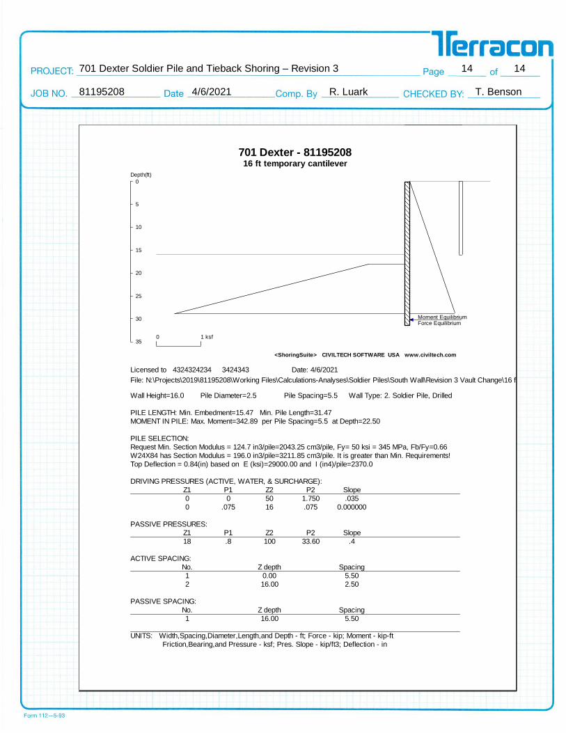
701 Dexter - 8119520816 ft temporary cantilever
<ShoringSuite> CIVILTECH SOFTWARE USA www.civiltech.com
Force EquilibriumMoment Equilibrium
Depth(ft)
0
5
10
15
20
25
30
350 1 ksf
Licensed to 4324324234 3424343 Date: 4/6/2021
File: N:\Projects\2019\81195208\Working Files\Calculations-Analyses\Soldier Piles\South Wall\Revision 3 Vault Change\16 ft temporary cantilevert.sh8
Wall Height=16.0 Pile Diameter=2.5 Pile Spacing=5.5 Wall Type: 2. Soldier Pile, Drilled
PILE LENGTH: Min. Embedment=15.47 Min. Pile Length=31.47
MOMENT IN PILE: Max. Moment=342.89 per Pile Spacing=5.5 at Depth=22.50
PILE SELECTION:
Request Min. Section Modulus = 124.7 in3/pile=2043.25 cm3/pile, Fy= 50 ksi = 345 MPa, Fb/Fy=0.66
W24X84 has Section Modulus = 196.0 in3/pile=3211.85 cm3/pile. It is greater than Min. Requirements!
Top Deflection = 0.84(in) based on E (ksi)=29000.00 and I (in4)/pile=2370.0
DRIVING PRESSURES (ACTIVE, WATER, & SURCHARGE):
Z1 P1 Z2 P2 Slope
0 0 50 1.750 .035
0 .075 16 .075 0.000000
PASSIVE PRESSURES:
Z1 P1 Z2 P2 Slope
18 .8 100 33.60 .4
ACTIVE SPACING:
No. Z depth Spacing
1 0.00 5.50
2 16.00 2.50
PASSIVE SPACING:
No. Z depth Spacing
1 16.00 5.50
UNITS: Width,Spacing,Diameter,Length,and Depth - ft; Force - kip; Moment - kip-ft
Friction,Bearing,and Pressure - ksf; Pres. Slope - kip/ft3; Deflection - in