special specification 7087 water mains and service...
TRANSCRIPT
7087
1 - 97 07-16 OTU
Special Specification 7087
Water Mains and Service Lines
1. DESCRIPTION
Provide and install a complete water main system in accordance with the plans and specifications and in compliance with the Department's Utility Accommodation Policy (UAP)(Title 43, T.A.C., Sections 21.31-21.55). The water mains shall be of the sizes, materials and dimensions shown on the plans and shall include all pipe, all joints and connections to new and existing pipes, all valves, fittings, fire hydrants, pipe joint restraint systems, blocking, and incidentals, as may be required to complete the work.
The abbreviations AWWA, ASA, ASTM, and ANSI, as used in this specification, refer to the following organizations or technical societies:
AWWA – American Water Works Association
ASA – American Standards Association
ASTM – American Society for Testing and Materials
ANSI – American National Standards Institute
NSF – National Science Foundation
Where reference is made to specifications of the above organizations, it is to be construed to mean the latest standard in effect on the date of the proposal.
2. MATERIALS
All materials used in this project are to be new and unused unless otherwise specified on the plans, specifications or the proposal. The Contractor shall submit descriptive information and evidence that the materials and equipment the Contractor proposed for incorporation into the Work are of the kind and quality that meet the material requirements listed herein. The SAWS Material Specifications are part of this specification and are available on the SAWS website at http://www.saws.org/business_center/specs/matspecs/. Contractors may, when appropriate use products that are specified in these specifications however a Submittal is still required that clearly indicates the applicable SAWS Material Specification. The products listed in the SAWS Material Specifications shall not be considered as a pre-approved list and cannot be substituted for items called out on the Drawings or on bid form.
2.1. Ductile-Iron Pipe and Fittings.
2.1.1. Ductile-Iron Pipe: 3-Inch through 64-In.
All ductile-iron pipe is to be manufactured by process of centrifugal casting and is to conform to ANSI/AWWA Standard C151/A21.51.91, “American Standard for Ductile-Iron Pipe Centrifugally Cast with push-on or mechanical joints for Water or Other Liquids,” unless otherwise modified or supplemented herein.
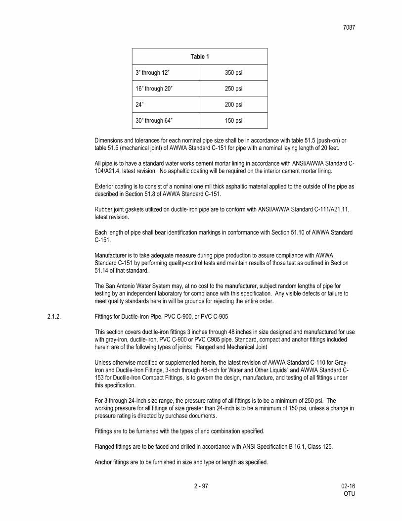
Pipe is to conform to the following pressure classes, based on Type 3 bedding conditions, a depth of bury of 6 feet and a working pressure of 150 psi:
7087
2 - 97 02-16 OTU
Table 1
3” through 12” 350 psi
16” through 20” 250 psi
24” 200 psi
30” through 64” 150 psi
Dimensions and tolerances for each nominal pipe size shall be in accordance with table 51.5 (push-on) or table 51.5 (mechanical joint) of AWWA Standard C-151 for pipe with a nominal laying length of 20 feet.
All pipe is to have a standard water works cement mortar lining in accordance with ANSI/AWWA Standard C-104/A21.4, latest revision. No asphaltic coating will be required on the interior cement mortar lining.
Exterior coating is to consist of a nominal one mil thick asphaltic material applied to the outside of the pipe as described in Section 51.8 of AWWA Standard C-151.
Rubber joint gaskets utilized on ductile-iron pipe are to conform with ANSI/AWWA Standard C-111/A21.11, latest revision.
Each length of pipe shall bear identification markings in conformance with Section 51.10 of AWWA Standard C-151.
Manufacturer is to take adequate measure during pipe production to assure compliance with AWWA Standard C-151 by performing quality-control tests and maintain results of those test as outlined in Section 51.14 of that standard.
The San Antonio Water System may, at no cost to the manufacturer, subject random lengths of pipe for testing by an independent laboratory for compliance with this specification. Any visible defects or failure to meet quality standards here in will be grounds for rejecting the entire order.
2.1.2. Fittings for Ductile-Iron Pipe, PVC C-900, or PVC C-905
This section covers ductile-iron fittings 3 inches through 48 inches in size designed and manufactured for use with gray-iron, ductile-iron, PVC C-900 or PVC C905 pipe. Standard, compact and anchor fittings included herein are of the following types of joints: Flanged and Mechanical Joint
Unless otherwise modified or supplemented herein, the latest revision of AWWA Standard C-110 for Gray-Iron and Ductile-Iron Fittings, 3-inch through 48-inch for Water and Other Liquids” and AWWA Standard C-153 for Ductile-Iron Compact Fittings, is to govern the design, manufacture, and testing of all fittings under this specification.
For 3 through 24-inch size range, the pressure rating of all fittings is to be a minimum of 250 psi. The working pressure for all fittings of size greater than 24-inch is to be a minimum of 150 psi, unless a change in pressure rating is directed by purchase documents.
Fittings are to be furnished with the types of end combination specified.
Flanged fittings are to be faced and drilled in accordance with ANSI Specification B 16.1, Class 125.
Anchor fittings are to be furnished in size and type or length as specified.
7087
3 - 97 02-16 OTU
The exterior of all fittings shall be provided with a petroleum asphaltic coating in accordance with the latest revision of AWWA Standard C110. The interior of flanged fittings supplied under this specification shall be either cement-mortar lined in accordance with the latest revision of AWWA Standard C104 or lined with a petroleum asphaltic material in accordance with the latest revision of AWWA Standard as specified. The interior of all other fittings supplied under this specification shall be cement-mortar lined in accordance with the latest revision of AWWA Standard C104.
Fittings for 2-inch size are to be manufacturer’s standard design, designed in accordance with applicable design standard of AWWA Standard C-110.
2.2. Concrete Steel Cylinder Pipe and Fittings: 20-inch and larger
This section covers prestressed reinforced-concrete water pipe with a steel cylinder and wire reinforcement in sizes 20 inches and larger.
Except as otherwise modified or supplemented herein AWWA Standard C301, "Prestressed Concrete Pressure Pipe - Steel Cylinder Type, for Water and Other Liquids" shall govern the design, component materials, manufacture, and testing of all concrete-steel cylinder pipe furnished under this specification.
Unless otherwise specified, all pipe shall be AWWA Class 150 and shall be designed for an internal working pressure of 150 psi and a minimum external load equivalent to 6 feet of earth cover. Where the depth of bury of the pipe is indicated to be greater than 6 feet in the contract specifications or on the drawings the design of the pipe shall be suitable for the earth loads indicated.
All data submitted by the contractor shall include a tabulated lay-out schedule with reference to the stationing and grade lines shown on the job plans. A design summary for each size of pipe furnished shall be provided for each pressure and depth of bury.
Each special and length of straight pipe shall have plainly marked on the inside of the bell end the class of pipe and identification marks sufficient to show the proper location of the pipe by reference to layout drawings.
Pipe 20 inches through 42 inches in size shall be furnished in nominal lengths of 20 to 32 feet; pipe 48 inches through 72 inches in size shall be furnished in nominal lengths of 16 feet except as this requirement shall be modified by design requirements of the particular job.
Each joint of pipe shall be furnished with a rubber gasket and a 12" diaper.
2.3. Steel Pipe, Fittings and Flanges
This section covers steel pipe 4-inches and larger in size and manufactured for the purpose of conveying water.
2.3.1. Steel Pipe
Steel pipe with nominal diameters from 6 through 20-in. shall conform to ASTM A 106, A 53 Grade B or A 139 Grade B standard weight class as the minimum
Steel Pipe greater than 20-inches shall conform to AWWA C-200 and AWWA M-11 except as modified herein or as required by the engineer for special circumstances.
Pipe shall be designed for a minimum of 150 psi working pressure with an additional 50% of the working pressure allowance for surge pressure unless otherwise specified. Pipe design shall be in accordance with AWWA M-11.
7087
4 - 97 02-16 OTU
Pipe shall be designed to cover conditions as shown on the plans. The design for deflection shall be in accordance with AWWA M-11.
Use of an enhanced /better soil backfill to limit deflection will be allowed with approval by the engineer. (Criteria will be based on AWWA M-11)
Pipe for use with sleeve-type couplings shall have plain ends at right angles to the axis.
Pipe length is to be nominal 50-feet lengths except for specials or as otherwise specified on the plans. Manufacturer is to prepare a lay schedule showing the location of each piece by a mark number with station and invert elevation at each bell end.
2.3.2. Fittings for Steel Pipe
Unless otherwise shown on the Plans, all specials and fittings shall conform to the dimensions of AWWA Standard C-208. Pipe material used in fittings shall be of the same material and thickness as the pipe. The minimum radius of elbows shall be 2.5 times the pipe diameter and the maximum miter angle on each section of the elbow shall not exceed 11 1/4 degrees (One cut elbow up to 22 1/2 deg.). If elbow radius is less than 2.5 x pipe diameter, stresses shall be checked per AWWA M-11 and wall thickness or yield strength increased if necessary. Fittings shall be equal in pressure design strength. Specials and fittings, unless otherwise shown on the Plans, shall be made of segmentally welded sections from hydrostatically tested pipe, with ends compatible with the type of joint or coupling specified for the pipe. All welds made after hydrostatic testing of the straight sections of pipe shall be checked per the requirements of AWWA C-200 Section 5.2.2.1.
2.3.3. Joints
2.3.3.1. Rolled-Groove Rubber Gasket Joint
The standard joint shall be rolled-groove rubber gasket joint unless otherwise noted on the plans. Rolled-grooved rubber gasket joints shall conform to AWWA C-200 Standard and as shown in Chapter 8 of AWWA M-11.
The o-ring rubber gasket shall have sufficient volume to approximately fill the area of the groove and shall conform to AWWA C-200.
The joint shall be suitable for a safe working pressure equal to the class of pipe furnished and shall operate satisfactorily with a deflection angle, the tangent of which is not to exceed 1.00/D where D is the outside diameter of the pipe in inches with a pull-out of 1 inch.
Rolled-Groove Rubber Gasket Joints may be furnished only by a manufacturer who has furnished pipe with joints of similar design for comparable working pressure. Pipe diameter, pipe length, and wall thickness that has been in successful service for a period of at least 5 years.
2.3.3.2. Lap weld
Lap field welded joints shall be used where tied joints are indicated on the plans. The standard bell shall provide for a 2 1/2-inch lap. The minimum lap shall be 1 inch. The design maximum joint deflection or offset shall be a 1" joint pull.
2.3.3.3. Mechanical Couplings
Mechanical couplings where indicated on the plans shall be Smith Blair Style 411, Baker Style 200, Brico Depend-O-Loc or equal. Insulating mechanical couplings where indicated on the plans shall be double insulated Smith Blair Style 416, Baker Style 216, or equal. Mechanical couplings shall be rated to meet or exceed the working pressures and surge pressure of the pipe.
7087
5 - 97 02-16 OTU
Couplings for buried service shall have all metal parts painted with Epoxy paint and conform to AWWA C-219.
Pipe ends for mechanical couplings shall conform to AWWA C-200 and M-11. The shop applied outside coating shall be held back as required for field assembly of the mechanical coupling or to the harness lugs or rings.
Harness lugs or rings and pipe ends shall be painted with one shop coat of epoxy conforming to AWWA C-210. The inside lining shall be continuous to the end of the pipe.
2.3.4. Steel Flanges
Flanges shall be in accordance with AWWA C207 Class D for operating pressures to 175 psi on 4 inch through 12 inch diameter, and operating pressures to 150 psi on diameters over 12 inches; or Flanges shall be AWWA C207 Class E for operating pressures up to 275 psi; or Flanges shall be AWWA C207 Class F for pressures to 300 psi. (drilling matches ANSI B 16.5 Class 250) Shop lining and coating shall be continuous to the end of the pipe or back of the flange. Flange faces shall be shop coated with a soluble rust preventive compound.
Gaskets: Full face, 1/8-inch thick, cloth-inserted rubber, Garlock 3000, John Crane Co. Style 777 or equal.
Bolts and Nuts for Flanges:
Bolts for flanges located indoors and in enclosed vaults and structures shall be carbon steel, ASTM A-307, Grade B for class B and D flanges and nuts shall be ASTM A-563, Grade A heavy hex. Bolts for class E and F flanges shall be ASTM A-193 grade B7 and nuts shall be ASTM A-194, grade 2 H, heavy hex.
Bolts for buried and submerged flanges and flanges located outdoors above ground or in open vaults in structures shall be Type 316 stainless steel conforming to ASTM A-193, Grade B8M, Class 1 for class B and D Flanges with ASTM A-194, Grade 8M nuts. For Class E and F flanges the bolts shall be ASTM A-194 grade 2H nuts with bolt and nuts to be zinc plated in accordance with ASTM B-633.
2.3.5. Linings and Coatings
2.3.5.1. Polyethylene Tape Coating
Prefabricated Multi-layer Cold Applied Tape Coating - the coating system for straight-line pipe shall be in accordance with AWWA Standard C-214. The system shall consist of three layers of polyethylene material with a nominal thickness of 80 mills when complete
2.3.5.2. Coating Repair
Coating repair shall be made using tape and primer conforming to AWWA Standard C-209, Type II. The tape and primer shall be compatible with the tape system used for straight-line pipe.
2.3.5.3. Coating of Fittings, Specials and Joints
2.3.5.3.1. General
Fittings, specials and joints which cannot be machine coated in accordance with above, shall be coated in accordance with AWWA Standard C-209. Prefabricated tape shall be Type II and shall be compatible with the tape system used for straight-line pipe. The system shall consist of 3 layers consisting of the following: Alternate coating methods for fittings specials and field joints would be Shrink sleeves per C-216, or paint per C-210, C-218, or C-222. The field coating shall completely encapsulate the joint bonds on o-ring joints.
2.3.5.3.2. Coating Repair
7087
6 - 97 02-16 OTU
Coating repair for fittings and specials shall be in accordance with the procedure described above for straight-line pipe and as recommended by the manufacturer.
2.3.5.4. Other Coating Systems
If specified shall be governed by the appropriate American Water Works Association standard.
2.3.5.5. Cement Mortar per AWWA C-205
2.3.5.5.1. Cement Mortar Lining of Steel Pipe
Except as otherwise provided in AWWA Standard C-205, interior surface of all steel pipe, fittings, and specials shall be cleaned and lined in the shop with cement-mortar lining applied centrifugally in conformity with AWWA Standard C-205.
The pipe ends shall be left bare where field joints occur as shown on the Plans. Ends of the linings shall be left square and uniform. Feathered or uneven edges will not be permitted.
Defective linings as identified in AWWA C-205 shall be removed from the pipe wall and shall be replaced to the full thickness required. Defective linings shall be cut back to a square shoulder in order to avoid feather edged joints.
Cement mortar lining shall be kept moist during storage and shipping.
2.3.5.5.2. Fittings
Fittings shall be lined and coated per AWWA C-205.
2.3.6. Steel Casing Pipe
The component materials, manufacture and testing of all steel pipe will conform to AWWA Standard C-200 for “Steel Water Pipe 6-in. and Larger”. The specified pipe size will be the actual inside diameter of the pipe, special or fitting in inches. The diameter and wall thickness of all steel pipe will conform to those shown on the plans.
Pipe will be either Grade A or Grade B, conforming to ASTM Designation A-53 or as shown on the plans.
Pipe ends will be beveled and suitable for field butt welding except as otherwise specified.
Pipe will receive a protective coating conforming to AWWA Standard C-203, “Coal-Tar Protective Coatings and Linings for Steel Pipelines – Enamel and Tape Hot Applied”.
Pipe length will be nominal 40 ft. lengths except for specials or as otherwise specified on the plans. Standard and specials will be within 1/16-in. (plus or minus) of the specified or theoretical lengths.
2.3.7. Quality Assurance
Commercial Standards (All manufacturing tolerances referenced in the below standards apply unless specifically excluded).
ANSI/AWWA C-200 Standard for Steel Water Pipe 6 Inches and Larger.
ANSI/AWWA C-205 Standard for Cement-Mortar Protective Lining and Coating for Steel Water Pipe - 4 inch and Larger-Shop Applied
ANSI/AWWA C-206 Standard for Field Welding of Steel Water Pipe.
7087
7 - 97 02-16 OTU
ANSI/AWWA C-207 Standard for Steel Pipe Flanges for Water Works Service, 4" - 144".
ANSI/AWWA C-208 Standard for Dimensions for Fabricated Steel Water Pipe Fittings.
ANSI/AWWA C-209 Standard for Cold-Applied Tape Coatings for the Exterior of Special Sections, Connections, and Fittings for Steel Water Pipelines.
ANSI/AWWA C-210 Standard for Liquid-Epoxy Coating Systems for the Interior and Exterior of Steel Water Pipelines.
ANSI/AWWA C-214 Standard for Tape Coating Systems for the Exterior of Steel Water Pipelines.
ANSI/AWWA C-216 Standard for Heat-Shrinkable Cross-Linked Polyolefin Coatings for the Exterior of Special Sections, Connections, and Fittings for Steel Water Pipelines.
ANSI/AWWA C-218 Standard for Liquid Coating the Exterior of Aboveground Steel Water Pipelines and Fittings.
ANSI/AWWA C-219 Standard for Bolted Sleeve-Type Couplings for Plain-End Pipe.
ANSI/AWWA C-222 Standard for Polyurethane Coatings for the Interior and Exterior of Steel Water Pipelines and Fittings.
AWWA M-11 Steel Pipe - A guide for Design and Installation.
ASTM A-106 Standard Specification for Seamless Carbon Steel Pipe for High-Temperature Service.
ASTM A-53 Standard Specification for Pipe, Steel, Black and Hot-Dipped, Zinc Coated Welded and Seamless.
ASTM E-165 Method for Liquid Penetrant Examination.
ASTM E-709 Guide for Magnetic Particle Examination.
ASME Section V Nondestructive Testing Examination.
ASME Section IX Welding and Brazing Qualification.
AWS B2.1 Standard for Welding Procedure and Welding Qualifications.
2.3.8. Qualifications
Manufacturers who are fully experienced, reputable, and qualified in the manufacture of the products to be furnished shall furnish all Steep pipe and fittings. The pipe and fittings shall be designed, constructed and installed in accordance with the best practices and methods and shall comply with these specifications as applicable
Pipe shall be the product of one manufacturer that has not less than five (5) years successful experience manufacturing pipe in the United States of the particular type and size indicated. All pipe manufacturing including cylinder production, lining, coating and fittings shall be produced by one manufacture. The pipe manufacturer must have a certified quality assurance program. This certified program shall be ISO 9001: 2000 or other equivalent nationally recognized program.
2.4. Polyvinyl Chloride Pipe and Fittings.
2.4.1. Polyvinyl Chloride Pipe, 4-inch through 12-inch (C-900)
7087
8 - 97 02-16 OTU
This section covers 4" through 12" diameter polyvinyl chloride (PVC) pressure pipe made from class 12454A or 12454B compounds as determined by ASTM Standard D1784 and providing for a hydrostatic test basis (HDB) of 4,000 psi. All pipe furnished shall be in conformance with AWWA Standard C900, or latest revision thereof.
Except as noted on the plans or procurement specifications for specific jobs, all C900 PVC pipe shall be Class 150 (DR 18) having a sustained pressure requirement of 500 psi (ASTM D2241) and a minimum burst pressure of 755 psi (ASTM D1599). C900 PVC pipe installed in the SAWS High Pressure Zone shall be class 200 (DR 14) having a sustained pressure requirement of 650 psi (ASTM D1598) and a minimum burst pressure of 985 psi (ASTM D1599). Pipe pressure class shall be written on the pipe and as per most current applicable AWWA standards.
Dimensions and tolerances for each nominal pipe sizes shall be in accordance with Section 2.2, Table 1 of AWWA Standard C900.
Pipe shall be furnished in standard laying lengths of 20 feet (plus or minus one inch) unless otherwise noted. Each pipe shall have an integral bell formed on the pipe end, and be designed to be at least as strong as the pipe wall (ASTM D2472).
An elastomeric gasket shall be designed with a retainer ring, which "locks" the gasket into integral bell groove and shall be installed at the point of manufacturer. Gasket shall be in conformance with ASTM F477.
Each length of pipe furnished shall bear identification markings in conformance with Section 2.6 of AWWA Standard C900.
Pipe shall be bundled in pallets for ease of handling and storage. Pipe bundles (units) shall be packaged to provide structural support to insure that the weight of upper units shall not cause deformation to pipe in lower units. No pipes bundles shall be accepted which show evidence of ultraviolet radiation "sunburn" on exposed pipe as may be caused from extended unprotected storage conditions.
The manufacturer shall take adequate measures during pipe production to assure compliance with AWWA C900 by performing quality-control tests and maintaining results of those tests as outlined in Section 3 of that Standard. Submission of product shall constitute certification of compliance with this standard.
Inductive Tracer Detection Tape shall be placed directly above the centerline of all non-metallic pipe a minimum of 12 inches below subgrade or, in areas outside the limits of pavement, a minimum of 18
inches below finished grade to aid locating pipe in the future. The tracer tape shall be encased in a protective, inert, plastic jacket and color coded according to American Public Works Association Uniform Color Code. Except for minimum depth of cover, the tracer tape shall be placed according to manufacturer’s recommendations.
A one-year warranty shall be provided for all materials sold and delivered for use and incorporated into the San Antonio water distribution system. Such warranty shall take effect on the date that the pipe is received and accepted by an authorized representative of the San Antonio Water System.
User references and a claims history shall be provided for further investigation, prior to rending a final decision on the acceptance of the product to be furnished.
The San Antonio Water System may, at no cost to the manufacturer, subject random lengths of pipe to testing by an independent laboratory for compliance with this specification. Any visible defect of failure to meet the quality standards herein will be grounds for rejecting the entire order.
2.4.2. Polyvinyl Chloride Pipe, 14-inch through 36-inch (C-905)
7087
9 - 97 02-16 OTU
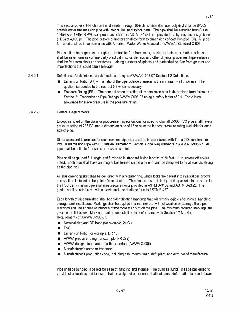
This section covers 14-inch nominal diameter through 36-inch nominal diameter polyvinyl chloride (PVC) potable water transmission pipe with integral bell and spigot joints. The pipe shall be extruded from Class 12454-A or 12454-B PVC compound as defined in ASTM D-1784 and provide for a hydrostatic design basis (HDB) of 4,000 psi. The pipe outside diameters shall conform to dimensions of cast iron pipe (CI). All pipe furnished shall be in conformance with American Water Works Association (AWWA) Standard C-905.
Pipe shall be homogenous throughout. It shall be free from voids, cracks, inclusions, and other defects. It shall be as uniform as commercially practical in color, density, and other physical properties. Pipe surfaces shall be free from nicks and scratches. Joining surfaces of spigots and joints shall be free from gouges and imperfections that could cause leakage.
2.4.2.1. Definitions. All definitions are defined according to AWWA C-905-97 Section 1.2 Definitions.
Dimension Ratio (DR) – The ratio of the pipe outside diameter to the minimum wall thickness. The
quotient is rounded to the nearest 0.5 when necessary.
Pressure Rating (PR) – The nominal pressure rating of transmission pipe is determined from formulas in
Section 5: Transmission-Pipe Ratings AWWA C905-97 using a safety factor of 2.0. There is no
allowance for surge pressure in the pressure rating.
2.4.2.2. General Requirements
Except as noted on the plans or procurement specifications for specific jobs, all C-905 PVC pipe shall have a pressure rating of 235 PSI and a dimension ratio of 18 or have the highest pressure rating available for each size of pipe.
Dimensions and tolerances for each nominal pipe size shall be in accordance with Table 2 Dimensions for PVC Transmission Pipe with CI Outside Diameter of Section 3 Pipe Requirements in AWWA C-905-97. All pipe shall be suitable for use as a pressure conduit.
Pipe shall be gauged full length and furnished in standard laying lengths of 20 feet ± 1 in. unless otherwise noted. Each pipe shall have an integral bell formed on the pipe end, and be designed to be at least as strong as the pipe wall.
An elastomeric gasket shall be designed with a retainer ring, which locks the gasket into integral bell groove and shall be installed at the point of manufacture. The dimensions and design of the gasket joint provided for the PVC transmission pipe shall meet requirements provided in ASTM D-3139 and ASTM D-2122. The gasket shall be reinforced with a steel band and shall conform to ASTM F-477.
Each length of pipe furnished shall bear identification markings that will remain legible after normal handling, storage, and installation. Markings shall be applied in a manner that will not weaken or damage the pipe. Markings shall be applied at intervals of not more than 5 ft. on the pipe. The minimum required markings are given in the list below. Marking requirements shall be in conformance with Section 4.7 Marking Requirements of AWWA C-905-97.
Nominal size and OD base (for example, 24 CI).
PVC.
Dimension Ratio (for example, DR 18).
AWWA pressure rating (for example, PR 235).
AWWA designation number for this standard (AWWA C-905).
Manufacturer’s name or trademark.
Manufacturer’s production code, including day, month, year, shift, plant, and extruder of manufacture.
Pipe shall be bundled in pallets for ease of handling and storage. Pipe bundles (Units) shall be packaged to provide structural support to insure that the weight of upper units shall not cause deformation to pipe in lower
7087
10 - 97 02-16 OTU
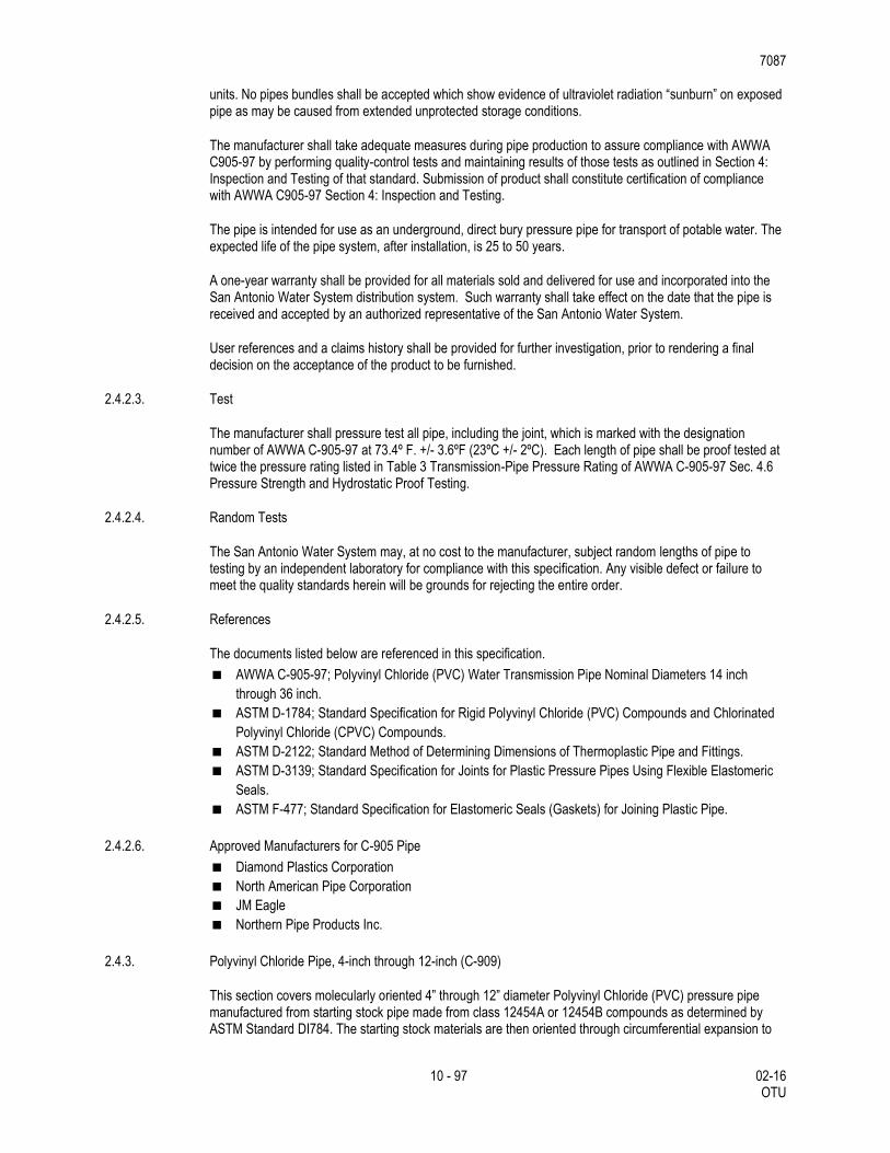
units. No pipes bundles shall be accepted which show evidence of ultraviolet radiation “sunburn” on exposed pipe as may be caused from extended unprotected storage conditions.
The manufacturer shall take adequate measures during pipe production to assure compliance with AWWA C905-97 by performing quality-control tests and maintaining results of those tests as outlined in Section 4: Inspection and Testing of that standard. Submission of product shall constitute certification of compliance with AWWA C905-97 Section 4: Inspection and Testing.
The pipe is intended for use as an underground, direct bury pressure pipe for transport of potable water. The expected life of the pipe system, after installation, is 25 to 50 years.
A one-year warranty shall be provided for all materials sold and delivered for use and incorporated into the San Antonio Water System distribution system. Such warranty shall take effect on the date that the pipe is received and accepted by an authorized representative of the San Antonio Water System.
User references and a claims history shall be provided for further investigation, prior to rendering a final decision on the acceptance of the product to be furnished.
2.4.2.3. Test
The manufacturer shall pressure test all pipe, including the joint, which is marked with the designation number of AWWA C-905-97 at 73.4º F. +/- 3.6ºF (23ºC +/- 2ºC). Each length of pipe shall be proof tested at twice the pressure rating listed in Table 3 Transmission-Pipe Pressure Rating of AWWA C-905-97 Sec. 4.6 Pressure Strength and Hydrostatic Proof Testing.
2.4.2.4. Random Tests
The San Antonio Water System may, at no cost to the manufacturer, subject random lengths of pipe to testing by an independent laboratory for compliance with this specification. Any visible defect or failure to meet the quality standards herein will be grounds for rejecting the entire order.
2.4.2.5. References
The documents listed below are referenced in this specification.
AWWA C-905-97; Polyvinyl Chloride (PVC) Water Transmission Pipe Nominal Diameters 14 inch
through 36 inch.
ASTM D-1784; Standard Specification for Rigid Polyvinyl Chloride (PVC) Compounds and Chlorinated
Polyvinyl Chloride (CPVC) Compounds.
ASTM D-2122; Standard Method of Determining Dimensions of Thermoplastic Pipe and Fittings.
ASTM D-3139; Standard Specification for Joints for Plastic Pressure Pipes Using Flexible Elastomeric
Seals.
ASTM F-477; Standard Specification for Elastomeric Seals (Gaskets) for Joining Plastic Pipe.
2.4.2.6. Approved Manufacturers for C-905 Pipe
Diamond Plastics Corporation
North American Pipe Corporation
JM Eagle
Northern Pipe Products Inc.
2.4.3. Polyvinyl Chloride Pipe, 4-inch through 12-inch (C-909)
This section covers molecularly oriented 4” through 12” diameter Polyvinyl Chloride (PVC) pressure pipe manufactured from starting stock pipe made from class 12454A or 12454B compounds as determined by ASTM Standard DI784. The starting stock materials are then oriented through circumferential expansion to
7087
11 - 97 02-16 OTU
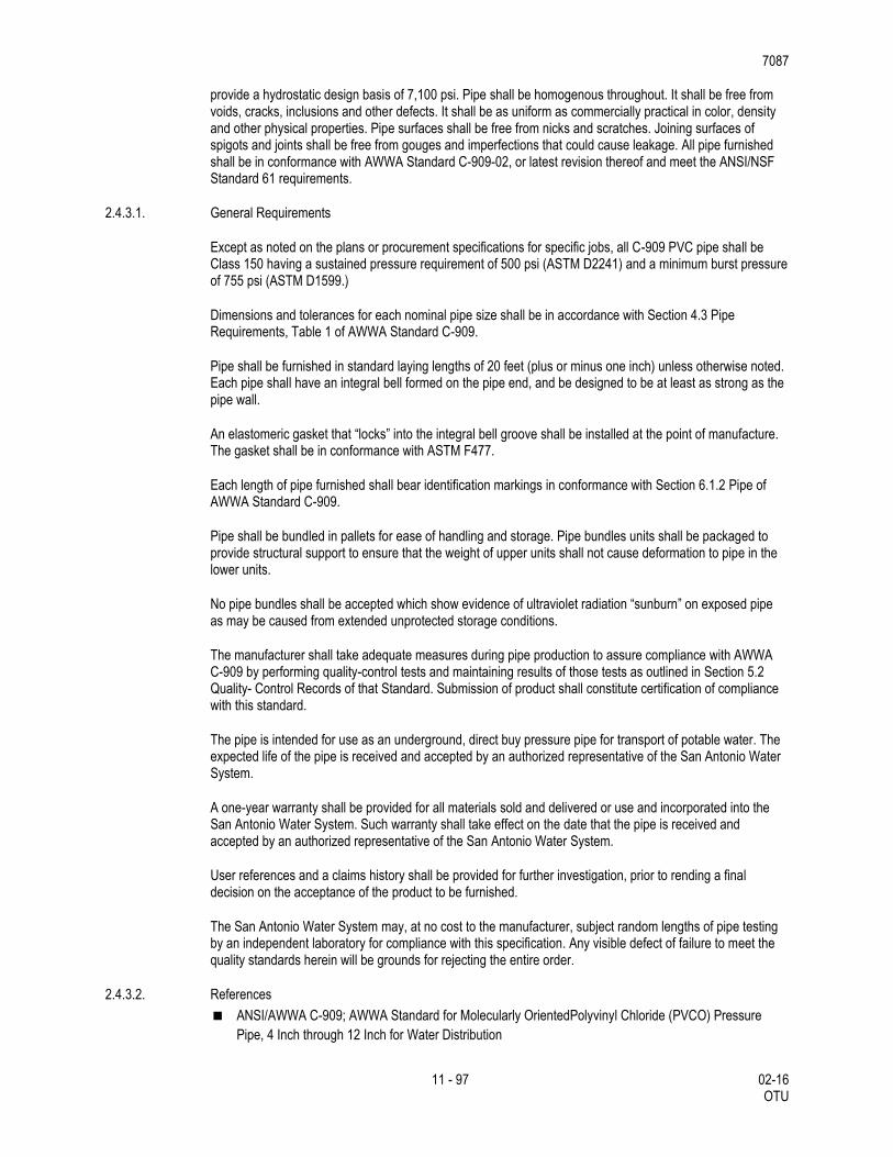
provide a hydrostatic design basis of 7,100 psi. Pipe shall be homogenous throughout. It shall be free from voids, cracks, inclusions and other defects. It shall be as uniform as commercially practical in color, density and other physical properties. Pipe surfaces shall be free from nicks and scratches. Joining surfaces of spigots and joints shall be free from gouges and imperfections that could cause leakage. All pipe furnished shall be in conformance with AWWA Standard C-909-02, or latest revision thereof and meet the ANSI/NSF Standard 61 requirements.
2.4.3.1. General Requirements
Except as noted on the plans or procurement specifications for specific jobs, all C-909 PVC pipe shall be Class 150 having a sustained pressure requirement of 500 psi (ASTM D2241) and a minimum burst pressure of 755 psi (ASTM D1599.)
Dimensions and tolerances for each nominal pipe size shall be in accordance with Section 4.3 Pipe Requirements, Table 1 of AWWA Standard C-909.
Pipe shall be furnished in standard laying lengths of 20 feet (plus or minus one inch) unless otherwise noted. Each pipe shall have an integral bell formed on the pipe end, and be designed to be at least as strong as the pipe wall.
An elastomeric gasket that “locks” into the integral bell groove shall be installed at the point of manufacture. The gasket shall be in conformance with ASTM F477.
Each length of pipe furnished shall bear identification markings in conformance with Section 6.1.2 Pipe of AWWA Standard C-909.
Pipe shall be bundled in pallets for ease of handling and storage. Pipe bundles units shall be packaged to provide structural support to ensure that the weight of upper units shall not cause deformation to pipe in the lower units.
No pipe bundles shall be accepted which show evidence of ultraviolet radiation “sunburn” on exposed pipe as may be caused from extended unprotected storage conditions.
The manufacturer shall take adequate measures during pipe production to assure compliance with AWWA C-909 by performing quality-control tests and maintaining results of those tests as outlined in Section 5.2 Quality- Control Records of that Standard. Submission of product shall constitute certification of compliance with this standard.
The pipe is intended for use as an underground, direct buy pressure pipe for transport of potable water. The expected life of the pipe is received and accepted by an authorized representative of the San Antonio Water System.
A one-year warranty shall be provided for all materials sold and delivered or use and incorporated into the San Antonio Water System. Such warranty shall take effect on the date that the pipe is received and accepted by an authorized representative of the San Antonio Water System.
User references and a claims history shall be provided for further investigation, prior to rending a final decision on the acceptance of the product to be furnished.
The San Antonio Water System may, at no cost to the manufacturer, subject random lengths of pipe testing by an independent laboratory for compliance with this specification. Any visible defect of failure to meet the quality standards herein will be grounds for rejecting the entire order.
2.4.3.2. References
ANSI/AWWA C-909; AWWA Standard for Molecularly OrientedPolyvinyl Chloride (PVCO) Pressure
Pipe, 4 Inch through 12 Inch for Water Distribution
7087
12 - 97 02-16 OTU
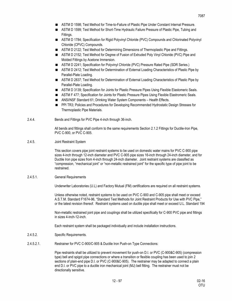
ASTM D 1598; Test Method for Time-to-Failure of Plastic Pipe Under Constant Internal Pressure.
ASTM D 1599; Test Method for Short-Time Hydraulic Failure Pressure of Plastic Pipe, Tubing and
Fittings.
ASTM D 1784; Specification for Rigid Polyvinyl Chloride (PVC) Compounds and Chlorinated Polyvinyl
Chloride (CPVC) Compounds.
ASTM D 2122; Test Method for Determining Dimensions of Thermoplastic Pipe and Fittings.
ASTM D 2152; Test Method for Degree of Fusion of Extruded Poly Vinyl Chloride (PVC) Pipe and
Molded Fittings by Acetone Immersion.
ASTM D 2241; Specification for Polyvinyl Chloride (PVC) Pressure Rated Pipe (SDR Series.)
ASTM D 2412; Test Method for Determination of External Loading Characteristics of Plastic Pipe by
Parallel-Plate Loading.
ASTM D 2837; Test Method for Determination of External Loading Characteristics of Plastic Pipe by
Parallel-Plate Loading.
ASTM D 3139; Specification for Joints for Plastic Pressure Pipes Using Flexible Elastomeric Seals.
ASTM F 477; Specification for Joints for Plastic Pressure Pipes Using Flexible Elastromeric Seals.
ANSI/NSF Standard 61; Drinking Water System Components – Health Effects.
PPI TR3; Policies and Procedures for Developing Recommended Hydrostatic Design Stresses for
Thermoplastic Pipe Materials.
2.4.4. Bends and Fittings for PVC Pipe 4-inch through 36-inch.
All bends and fittings shall conform to the same requirements Section 2.1.2 Fittings for Ductile-Iron Pipe, PVC C-900, or PVC C-905.
2.4.5. Joint Restraint System
This section covers pipe joint restraint systems to be used on domestic water mains for PVC C-900 pipe sizes 4-inch through 12-inch diameter and PVC C-905 pipe sizes 16-inch through 24-inch diameter, and for Ductile Iron pipe sizes from 4-inch through 24-inch diameter. Joint restraint systems are classified as “compression, “mechanical joint” or “non-metallic restrained joint” for the specific type of pipe joint to be restrained.
2.4.5.1. General Requirements
Underwriter Laboratories (U.L) and Factory Mutual (FM) certifications are required on all restraint systems.
Unless otherwise noted, restraint systems to be used on PVC C-900 and C-905 pipe shall meet or exceed A.S.T.M. Standard F1674-96, “Standard Test Methods for Joint Restraint Products for Use with PVC Pipe,” or the latest revision thereof. Restraint systems used on ductile pipe shall meet or exceed U.L. Standard 194
Non-metallic restrained joint pipe and couplings shall be utilized specifically for C-900 PVC pipe and fittings in sizes 4-inch-12-inch.
Each restraint system shall be packaged individually and include installation instructions.
2.4.5.2. Specific Requirements.
2.4.5.2.1. Restrainer for PVC C-900/C-905 & Ductile Iron Push-on Type Connections:
Pipe restraints shall be utilized to prevent movement for push-on D.I. or PVC (C-900&C-905) (compression type) bell and spigot pipe connections or where a transition or flexible coupling has been used to join 2 sections of plain-end pipe D.I. or PVC (C-900&C-905). The restrainer may be adapted to connect a plain end D.I. or PVC pipe to a ductile iron mechanical joint (MJ) bell fitting. The restrainer must not be directionally sensitive.
7087
13 - 97 02-16 OTU
The pipe shall be restrained by a split retainer band. The band shall be cast ductile iron, meeting or exceeding ASTM A-536-80, Grade 65-45-12. The inside face or contact surface of the band shall be of sufficient width to incorporate cast or machined non-directionally sensitive serration to grip the outside circumference of the pipe. The serration shall provide full (360 °) contact and maintain pipe roundness and avoid any localized points of stress. The split band casting shall be designed to “bottom-out” before clamping bolt forces (110ft-lb minimum torque) can over-stress the pipe, but will provide full non-directionally sensitive restraint at the rated pressures.
Bolts and nuts used to attach the split retainer ring shall comply with ANSI B-18.2/18.2.2, SAE Grade 5. Tee-bolts, nuts and restraining rods shall be fabricated from high-strength, low-alloy steel per AWWA C-111-90.
The split ring type non-directionally sensitive restrainer system shall be capable of a test pressure twice the maximum sustained working pressure listed in section D and be for both D.I. and/or PVC C-900.
Restraint systems sizes 6 through 12-inch shall be capable of use for both ductile iron and/or PVC C-900.
The restraint system may consist of 2 types: the two split retainer rings and for new construction use only the 1 split and 1 solid cast backup ring.
2.4.5.2.2. Compression Ring Fitting Restrainer for Ductile Iron Pipe & PVC C-900.
Compression ring with follower gland type of restrainer may be utilized in conjunction with Mechanical Joint (MJ) bell end ductile iron pipe fittings for restraining PVC C-900 and ductile iron pipe.
The system shall utilize a standard MJ gasket with a color-coded compression ring and replacement gland conforming to ASTM A-536-80, Grade 65-45-12.
Standard MJ fitting Tee-bolts and nuts shall be fabricated from high strength steel conforming to ANSI AWWA C-111/A-21.11 and AWWA C-153/A-21.53-88.
Standard MJ gasket shall be virgin SBR meeting ASTM D-2000 3 BA 715 or 3 BA 515.
The restraint system shall be capable of a test pressure twice the maximum sustained working pressure listed in section D.
2.4.5.2.3. Non-metallic restrained joint pipe and couplings for PVC C-900 Type Connections:
Gasketed restrained coupling connections shall join two sections of factory grooved PVC (C-900) pipe. The restrainer coupling or must not be directionally sensitive.
The coupling shall incorporate twin elastomeric sealing gaskets meeting the requirements of ASTM F-477 and shall be DR-14 Class 200 C-900 PVC in all applications, meeting or exceeding the performance requirements of AWWA C-900, latest revision. The inside face or contact surface of the coupling connection shall be of sufficient width to incorporate a factory machined non-directionally sensitive groove in both pipe and coupling to grip the outside circumference of the pipe. The couplings shall provide full (360 °) contact and maintain pipe roundness and avoid and localized points of stress. The coupling shall be designed with an internal stop to align the precision-machined grooves in the coupling and pipe prior to installation of a non-metallic thermoplastic restraint spleen, and will provide full non-directionally sensitive restraint at the rated pressures.
High-strength flexible thermoplastic spleens shall be inserted into mating precision–machined grooves in the pipe and coupling to provide full non-directional restraint with evenly distributed loading.
7087
14 - 97 02-16 OTU
The non-metallic restrained joint pipe and couplings for PVC C-900 type non-directionally sensitive restrainer system shall be capable of a test pressure twice the maximum sustained working pressure listed in Section D and be for PVC (C-900) pipe sizes 4 through 12-inch.
Non-metallic restrained joint pipe and couplings for PVC C-900 restrained systems sizes 4 through 12-inch shall be capable of use for both Class 150 (DR 18) and 4 through 8-inch for Class 200 (DR 14) PVC C-900 pipe.
The non- metallic restrained joint pipe and couplings for PVC C-900 restraint system shall consist of a pipe and couplings system produced by the same manufacturer meeting the performance qualifications of Factory Mutual (FM) and Underwriters Lab (UL).
2.4.5.2.4. Fitting Restraint for Ductile Iron Pipe (only):
Radial bolt type restrainer systems shall be limited to ductile iron pipe in conjunction with Mechanical Joint (MJ) bell end pipe of fittings. The system shall utilize a standard MJ gasket with a ductile iron replacement gland conforming to ASTM A-536-80. The gland dimensions shall conform to Standard MJ bolt circle criteria.
Individual wedge restrainers shall be ductile iron heat treated to a minimum hardness of 370 BHN. The wedge screws shall be compressed to the outside wall of the pipe using a shoulder bolt and twist-off nuts to insure proper actuating of the restraining system.
Standard MJ fitting Tee-bolts and nuts shall be high strength steel conforming to AWWA C111/A21.11and C153/A21.53-88.
Standard MJ gasket shall be virgin SBR meeting ASTM D-2000 3 BA 715 or 3 BA 515.
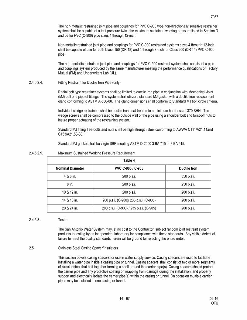
2.4.5.2.5. Maximum Sustained Working Pressure Requirement
Table 4
Nominal Diameter PVC C-900 / C-905 Ductile Iron
4 & 6 in. 200 p.s.i. 350 p.s.i.
8 in. 200 p.s.i. 250 p.s.i.
10 & 12 in. 200 p.s.i. 200 p.s.i.
14 & 16 in. 200 p.s.i. (C-900)/ 235 p.s.i. (C-905) 200 p.s.i.
20 & 24 in. 200 p.s.i. (C-900) / 235 p.s.i. (C-905) 200 p.s.i.
2.4.5.3. Tests:
The San Antonio Water System may, at no cost to the Contractor, subject random joint restraint system products to testing by an independent laboratory for compliance with these standards. Any visible defect of failure to meet the quality standards herein will be ground for rejecting the entire order.
2.5. Stainless Steel Casing Spacer/Insulators
This section covers casing spacers for use in water supply service. Casing spacers are used to facilitate installing a water pipe inside a casing pipe or tunnel. Casing spacers shall consist of two or more segments of circular steel that bolt together forming a shell around the carrier pipe(s). Casing spacers should protect the carrier pipe and any protective coating or wrapping from damage during the installation, and properly support and electrically isolate the carrier pipe(s) within the casing or tunnel. On occasion multiple carrier pipes may be installed in one casing or tunnel.
7087
15 - 97 02-16 OTU
2.5.1. General Requirements
The San Antonio Water System (SAWS) reserves the right to limit the purchase of casing spacers from the manufacturers and to the models specified as shown in paragraph 4, providing such casing spacers conform to the provisions contained herein.
Casing spacers shall be eight inches (8”) long for carrier pipes up to 16- inch diameters and twelve inches (12”) long for larger carrier pipe sizes. Manufacturer’s approval in writing shall be required for installations exceeding 300 ft. in length, carrier pipes in excess of 48- inch diameter or multiple carrier pipes in one casing or tunnel.
Casing spacers shall have a minimum 14-gauge steel band and 10 gauge steel riser when required. The band, risers and connecting studs shall be welded and cleaned at the factory before the application of a fluidized bed fusion bonded PVC coating. Stainless steel (type 304) casing spacer is an acceptable alternative.
The fluidized bed fusion bonded PVC coating shall be between 10-16 mils thickness. The PVC coating shall provide good resistance to acids and alkalize and excellent resistance under ASTM B117 salt spray tests. The coating shall have a minimum 1380volts/mil per ASTM D149-61 short time 0.010” test and a Durometer-shore A@ (10 sec) of 80 per ASTM D1706-61T. Epoxy coatings are not an acceptable alternative.
The spacers shall have a flexible PVC liner of 0.09-inch thickness with Durometer “A” 85-90 hardness and a minimum 58,000- volt dielectric strength (60,000-volt minimum Surge Test.) Moisture absorption shall not exceed 1%.
The runners shall be of high pressure molded glass reinforced polyester with a minimum compressive strength of 18,000 psi per ASTM D695, flexural strength of 25, 300 psi per ASTM D790, tensile strength of 17,600 psi per ASTM D638 and Rockwell hardness (M) of 90 per ASTM D785. The riser shall be designed and fabricated to place the runner (skid) in full contact with the inside surface of the casing pipe. This evenly distributes the load force to all support members. The ends of all runners shall be shaped to resist hanging or sticking inside casing during installation of the carrier pipe. Polyethylene runners are not acceptable.
Runners shall be a minimum of 1.0 inch in width and a minimum of 7 inches long for carrier pipes up to 16”, and a minimum of 2.0 inches in width and 11 inches long for larger carrier pipes. Bolts on runners are not acceptable. The runners shall be attached to the band or riser by 3/8 the wearing surface on the runner. The recess shall be filled with a corrosion inhibiting filler. There shall be four runners per casing spacer for carrier pipes up to 12” diameter, six runners for 14” through 36” and eight or more runners for carrier pipes over 36” diameter. Number of bottom runners shall be multiples of two. Number of top runners shall be multiples of two.
The band section shall be bolted together with 5/16” cadmium-plated studs, nuts and washers. There shall be six sets per 8” long casing spacer and eight sets per 12” long spacer. Stainless steel casing spacers shall be furnished with stainless steel studs, nuts and washers.
Casing spacers shall have ample riser height to limit vertical movement of the carrier pipe in the casing. A minimum of 1” to 2” clearance shall be provided between the top runner and the ID of the casing or tunnel.
Continuous operating temperatures for the PVC Coated Casing Spacers should not exceed 150°F. Stainless steel casing shall be used in applications where continuous operating temperatures exceed 150°F.
Unless noted otherwise, casing spacers and end seals shall be required on all carrier pipes installed in casing or tunnel applications.
2.5.2. Quality Assurance
7087
16 - 97 02-16 OTU
All casing spacers are to be manufactured in accordance to NACE International Recommend Practice RP 0286-97 (Isolation Spacers.) Each casing spacer shall be manufactured in the USA at a facility that has a Registered ISO 9002 Quality Management System or be in the process of achieving this certification by March 2005. Non-compliance to this registered commercial quality system requirement by March 2005 will result in removal of the manufacturer’s product from paragraph 4 approved manufacturers.
If on receipt of casing spacers they are found to be non-compliant, the manufacturer shall replace the defective casing spacer with a casing spacer that meets the San Antonio Water System’s specifications, at no charge to San Antonio Water System.
If San Antonio Water System audits, product inspection and performance data review in accordance to these specifications determine excessive casing spacer Noncompliance, the manufacturer will be subject to removal by the Products Standard Committee. Copy of the current ISO 9002 registration (or written documentation of being “in the process of achieving ISO registration,” prior to March 2005) shall be provided with material submittal.
2.6. Copper Tubing and Brass Fittings for Copper Service Lines.
2.6.1. Copper Tubing.
This section covers copper tubing in nominal sizes of 3/4", 1", 1-1/2" and 2”.
2.6.1.1. General Requirements
Copper service tubing shall be annealed seamless Type "K" and meet ASTM B-88 bearing NSF Standard 61 approval and be rated at 150 psi working pressure..
3/4" and 1" copper tubing shall be furnished in sixty-foot coils or one hundred- foot coil as specified; 1-1/2" shall be furnished in twenty-foot lengths, forty-foot coils or sixty-foot coils as specified, and 2" shall be furnished in twenty-foot lengths or forty foot coils as specified.
Copper tubing is the only allowable material for small service lines.
2.6.2. Brass Fittings.
This section covers waterworks brass goods, such as, corporation stops, curb stops, couplings, connectors, nipples, etc.
2.6.2.1. General Requirements
The brass composition shall conform to ASTM Specifications B-62, or latest revision thereof, fittings shall conform to ANSI/AWWA Specifications C-800, or latest revision thereof.
All brass components in contact with potable water must be “lead free” and marked by stamping, etching or casting “NL” in the main body made from either CDA/UNS Brass Alloys C89520 in accordance with ASTM B584; or C89833. Brass saddles shall be made from CDA/UNS C83600.
Any brass component not in contact with potable water shall be made of 85-5-5-5 brass as defined per ASTM B62, ASTM B584 and AWWA C-800.
All service fittings shall be certified as suitable for contact with drinking water by an ANSI accredited organization in accordance with ANSI/NSF standard 61, Drinking Water Systems Components-Health effects section 8. Proof of certification is required. The lead content of the wetted components in contact with potable water shall also be verified by an ANSI accredited testing facility.
7087
17 - 97 02-16 OTU
All brass fittings and valves shall have the manufacturers name and/or trademark integrally stamped, or cast into it indicating that the product is manufactured from the low-lead alloy as specified. Another marking such as “NL”, “EBII”,”FD” or other commonly accepted identifier, indicating the alloy as “No-lead”; shall also be cast or stamped into the fitting or valve.
Painting, printing, sticker, or decals attesting to the components “no-lead” certification shall not be permitted.
All casting shall have a natural, clean uniform and smooth surface, and be free from internal porosity.
All machining shall be done in a workmanlike manner and within the acceptable tolerances.
2.6.2.2. Design Criteria for Ball Type Curb Stops/Angle Valves
All Curb Stop, Corporation and Angle valves shall be ball valves. "Inverted/Ground Key,” type angle valves will not be accepted.
Ball type valves will not have a stop.
All ball valves, couplings and adapters will be pressure rated to 300 psi, and will be supplied with blowout proof stainless steel stems with double SBR, NBR or EPDM O-ring steam seal.
Stem and cap assembly will be two-piece design and will withstand minimum 200 ftp of torque.
Ball seats will be made with unfilled Teflon or EPDM for resilience and minimal friction.
Ball will be lead free cast brass or stainless design. Coated ball is not permitted.
All fittings shall have a lifetime guarantee against lead leachate from the casting.
The reduced port design not will be acceptable.
Pack Joints will not be accepted.
2.7. Gate Valves, Tapping Valves and Tapping Sleeves.
2.7.1. Resilient-Seated Gate and Tapping Valves ANSI/AWWA C509-01
This product specification covers resilient seated gate valves, with nominal diameters of 3 in., 4 in., 6 in., 8 in., 10 in., 12 in., 16 in., and 20 in. Sizes refer to the nominal diameter, in inches, of the waterway through the inlet and outlet connections and the closure area. All products furnished shall conform to the American National Standards Institute and American Water Works Association C509. .
2.7.1.1. Definitions
All definitions are defined according to ANSI/AWWA C509-01:
Cosmetic Defect: A blemish, which has no effect on the ability of the component to meet the structural design and production test requirements of this standard. Should the blemish or the activity of plugging, welding, grinding, or repairing of such blemish cause the component to fail these requirements, then the blemish shall be considered a structural defect.
Flanged Joint: The flanged and bolted joint as described in ANSI/AWWA C110/A21.10.
Mechanical Joint: The gasket and bolted joint as described in ANSI/AWWA C111/A21.11.
Push-on Joint: The single rubber gasket joint as described in ANSI/AWWA C111/A21.11.
7087
18 - 97 02-16 OTU
Structural Defect: A flaw that causes the component to fail the structural design or test requirement of this standard. This includes, but is not limited to imperfections that result in leakage through the walls of a casting, failure to meet the minimum wall-thickness requirement, or failure to meet production tests.
Tapping Valve: A special gate valve designed with end connections and an unobstructed waterway to provide proper alignment and positioning of a tapping sleeve, valve, and machine for tapping pipe dry or under pressure as described in AWWA C509 Section 1.2 Definitions and MSS SP-60.
2.7.1.2. General Requirements
Except as otherwise modified or supplemented herein, AWWA Standard C-509-01 or the latest revision thereof, shall govern the design, component materials, construction; manufacture and testing of all resilient seated gate valves. Valves shall be suitable for frequent operation as well as service involving long periods of inactivity. Valves shall be NSF-61 certified.
The San Antonio Water System reserves the right to limit the purchase of resilient seat gate valves from manufacturers and to the models specified, as shown in Table 15, provided such resilient seat gate valves conform to the provision contained herein.
The minimum design working water pressure for gate valves with nominal diameters of 3 in., 4 in., 6 in., 8 in., 10 in., and 12 in. shall be 200 psig unless otherwise specified.
The minimum design working water pressure for gate valves with nominal diameters of 16 in., and 20 in. shall be 150 psig unless otherwise specified.
Valves shall be resilient-seated types, bronze mounted with non-rising stems. The closure member shall be fully encapsulated by an elastomer without thin spots or voids. When open the valve shall have a clear, full-port, unobstructed waterway.
Gray iron, ductile iron, steel, brass and bronze materials shall meet or exceed the material requirements of Section 2: Materials of AWWA C-509-01.
Gaskets, O-rings, Coatings, and elastomers shall meet or exceed the material requirements of Section 2: Materials of AWWA C-509-01.
The gate valves shall be designed and constructed for installation in either a horizontal or vertical position. Valves shall be designed for buried installation with stem in the vertical position and shall be furnished for mounting in a horizontal pipeline, unless otherwise specified.
Valve components of brass or bronze shall be manufactured to ASTM recognized alloy specifications of low zinc content bronze, as shown in Table 1 of Section 2.2.4. of ANSI/AWWA Standard C-509-01 or the latest revision thereof. Materials for the stem have minimum yield strength of 40,000 psi. A minimum elongation in 2 inches of 12% and shall be made of bronze per ASTM B763, alloy number UNS C99500. A maximum zinc content of 2% as shown in Table 2 Chemical Requirements of ASTM B763-96 or the latest revision thereof. Stem nut material shall be ASTM B-62 UNS C83600 or ASTM B-584 UNS C84400. The stem shall have a visible external marking at the top to indicate low-zinc, high strength material. The marking shall include a red plastic or neoprene washer placed around the top of the stem under the operating nut.
Valve ends shall be either flanged, tapping valve, mechanical joint, push-on joint or any combination thereof, as specified. All mechanical joint valves shall be supplied with glands, bolts, and gaskets. Valve body bolts and nuts shall meet the strength requirements of ASTM A-307 with dimensions conforming to ANSI B18.2.1. The size of the bolt head shall be equal to the size of the nut and shall be stainless steel in accordance with ASTM 276.
All gate valves shall open right (clockwise), unless otherwise specified.
7087
19 - 97 02-16 OTU
The following parts of the valve shall be made of either gray or ductile iron: bonnet, body, yoke, wrench nut, O-ring packing plate or seal plate, and gland follower. The gate may be made of gray or ductile iron.
If glands and bushings are used for NRS valves they shall be made of ASTM B-763 bronze UNS C99500. The stem shall be made of cast, forged, or rolled ASTM B-763 bronze UNS C99500. The stem nut material shall be ASTM B-62 bronze UNS C83600 or ASTM B-584 bronze UNS C84400. The gate may be made of bronze ASTM B-763 bronze UNS C99500. Stem seals shall be “O” ring type. The seals shall be designed for dynamic applications.
The design shall be such that the seal above the stem collar can be replaced with the valve under full pressure in the fully open position. Materials for the “O” ring packing plate shall be in accordance with Section 4.8.3 of the ANSI/AWWA C509-01 Standard or the latest revision thereof.
Enclosed and buried valves shall be coated inside and outside with a fusion bonded epoxy having a nominal 8 mils dry film thickness, which meets or exceeds AWWA C-550-01 and to the maximum extent possible shall be free of holidays. All coatings in contact with the potable water shall be approved for potable water immersion service per ANSI/NSF Standard 61.
The bidder shall submit with his proposal three sets of certified drawings showing the principal dimensions, general construction and material specification of the valve proposed. The number of turns to open (close) shall be clearly noted in the valve information submitted with the proposal documents. The number of turns to open or close the valve shall be consistent for each valve size for each approved manufacturer.
Valves furnished under this specification shall be supplied from the San Antonio Water System approved manufacturer list. To be included on the qualified product list, the manufacturer shall provide an Affidavit of Compliance in accordance with the Section 1.5 of the ANSI/AWWA C-509-01 Standard or latest revision thereof, to include compliance with San Antonio Water System Specification No. 21-02. Records of all tests performed in accordance with Section 6.1 and Section 6.2 of the ANSI/AWWA C-509-01 Standard or latest revision thereof will be made available or provided. These records will be representative test results for Section 6.1 and certificate of testing for Section 6.2. An affidavit of testing for the valve assembly as outlined in Section 6.2.2 of the ANSI/AWWA C-509-01 Standard, (350 ft-lbs) will also be provided. A copy of the manufacturer’s Quality Assurance Program will be submitted. Blueprints and parts list for the valve shall also be provided.
All gate valve parts shall be designed to withstand the following two pressure requirements, without being structurally damaged. (1) An internal test pressure of twice the rated design working pressure of the valve. (2) The full rated internal working pressure when the closure member is cycled once from a fully open to a fully closed position against the full rated unbalanced working water pressure. In addition to these pressure requirements, the valve assembly and mechanism shall be capable of withstanding an input torque as follows: 200 ft.-lbs. for a 3-in. nominal diameter. 200 ft.-lbs. for a 4-in. nominal diameter. 300 ft.-lbs. for a 6-in. nominal diameter. 300 ft.-lbs. for a 8-in. nominal diameter. 300 ft.-lbs. for a 10- in. nominal diameter. And 300 ft.-lbs. for a 12-in. nominal diameter. For sizes larger than a 12 in. nominal diameter refer to the manufacturer’s specifications.
Resilient seats shall be applied to the gate and shall seat against a corrosion resistant surface. The non-metallic seating surface shall be applied in a manner to withstand the action of line fluids and the operation of the sealing gate under long-term service. A metallic surface shall have a corrosion resistance equivalent to or better than bronze. A non-metallic surface shall be in compliance with ANSI/AWWA C-550. The gate must be fully encapsulated by an elastomer without thin spots or voids. Resilient seats shall be bonded. ASTM D-429 either method A or method B shall prove the method used for bonding or vulcanizing. For method A, the minimum strength shall not be less than 250 psi. For method B, the peel strength shall be 75 lb./in.
Flanged Ends: The end flanges of flanged valves shall conform to dimensions and drillings of ANSI/AWWA C-110/A21.10 or ANSI B-16.1, Class 125.
Mechanical Joint Ends: Mechanical joint bell dimensions shall conform to ANSI/AWWA C-111/A21.11.
7087
20 - 97 02-16 OTU
Push-on Joints: Push-on joints shall conform to the requirements of ANSI/AWWA C-111/A21.11.
The tapping valves shall be mechanical joints with tapping flange on the other end. The tapping valves shall be furnished complete with glands, bolts, and gaskets. The tapping valve shall have a clear unobstructed waterway.
The seat rings shall be of a large diameter to the permit entry of the full diameter tapping machine cutters. The valve end which mates with the tapping sleeve shall have an alignment lip to fit the recess in the tapping sleeve flange for proper alignment. The lip will be dimensioned in accordance with MSS SP-60 for valves 20-inch nominal pipe size and smaller.
All interchangeable parts shall conform to their required dimensions and shall be free from defects that could prevent proper functioning of the valve. When assembled, valves manufactured in accordance with this standard shall be well fitted and operate smoothly. All like parts of valves of the same model and size produced by the same manufacturer shall be interchangeable.
All castings shall be clean and sound, without defects that will weaken their structure or impair their service. Plugging, welding, or repairing of cosmetic defects is allowed. Repairing of structural defects is not allowed. Repaired valves shall comply with the testing requirements of this specification after repairs have been made. Repairs within the bolt circle of any flange face are not allowed.
All gate valves shall be hydrostatically tested with twice the specified rated pressure applied to one side of the gate and zero pressure applied to the other side. The test is to be made in each direction across the gate. All tests are to be performed at the manufacturer’s plant.
All gate valves shall be operated through a complete cycle in the position for which it was designed to ensure free and proper functioning of all parts in the intended manner. Any defects in workmanship shall be corrected and the test repeated until satisfactory performance is demonstrated. All tests are to be performed at the manufacturer’s plant.
A hydrostatic test pressure equal to twice the rated working pressure of the valve shall be applied to all assembled valves with the gates in the open position. The test shall show no leakage through the metal, pressure containing joints, or stem seals. All tests are to be performed at the manufacturer’s plant.
A test shall be made from each direction at rated working pressure to prove the sealing ability of each valve from both directions of flow. The test shall show no leakage through the metal, pressure containing joints, or past the seat. All tests are to be performed at the manufacturer’s plant.
Markings shall be cast on the bonnet or body of each valve and shall show the manufacturer’s name or mark, the year the valve casting was made, the size of the valve, and the designation of working water pressure, for example “200 W”.
The San Antonio Water System may, at no cost to the Contractor, subject random valves to testing by an independent laboratory for compliance with these standards. Any visible defect or failure to meet the quality standards herein will be grounds for rejecting the entire order and removal from the approval list.
Table 15 identifies specified manufacturers that are approved.
2.7.1.3. Workmanship
All parts of the resilient seat gate valve shall be designed and manufactured to the tolerances specified in ANSI/AWWA C-509-01 or latest revision thereof and this specification.
All parts of the resilient seat gate valve manufactured by a given manufacturer shall be interchangeable with like parts from another resilient seat gate valve of the same model and size and by the same manufacturer.
7087
21 - 97 02-16 OTU
All interchangeable parts shall conform to their required dimensions and shall be free from defects that could prevent proper functioning of the valve.
All castings shall be clean and sound, without defects that will weaken their structure or impair their service. Plugging, welding, or repairing of cosmetic defects is allowed. Repairing of structural defects is not allowed. Repaired valves shall comply with the testing requirements of this specification after repairs have been made. Repairs within the bolt circle of any flange face are not allowed.
The resilient seat gate valves shall be well fitted.
Operation of the resilient seat gate valve shall be smooth.
All parts shall be free of structural defects.
The resilient seat gate valve shall be watertight.
2.7.1.4. Painting
All exterior and interior surfaces of the valve shall be coated with epoxy, N.S.F. 61 certified. The epoxy shall have a nominal dry film thickness of 8 mils, and shall be in accordance with AWWA C-550, latest revision.
Coating shall be as close to holiday free as is technologically possible.
2.7.1.5. Testing
Hydrostatic Test: Hydrostatic Test shall be performed on the valve in accordance with Section 6.1 Proof of Design Testing of ANSI/AWWA C-509-01 or latest revision thereof.
Torque Test: Torque Test for prototype valves shall be performed on the valve in accordance with Section 6.1 Proof of Design Testing of ANSI/AWWA C-509-01 or latest revision thereof.
Leakage Test: Leakage Test shall be performed on the valve in accordance with Section 6.1 Proof of Design Testing of ANSI/AWWA C-509-01 or latest revision thereof.
Pressure Test: Pressure Test shall be performed on the valve in accordance with Section 6.1 Proof of Design Testing of ANSI/AWWA C-509-01 or latest revision thereof.
Operation Test: Operation Test shall be performed on the valve in accordance with Section 6.2 Production Testing of ANSI/AWWA C-509-01 or latest revision thereof.
Shell Test: Shell Test shall be performed on the valve in accordance with Section 6.2 Production Testing of ANSI/AWWA C-509-01 or latest revision thereof.
Seat Test: Seat Test shall be performed on the valve in accordance with Section 6.2 Production Testing of ANSI/AWWA C-509-01 or latest revision thereof.
An Affidavit of Compliance certifying that all required tests have been performed shall be provided in accordance with Section 6.3 Affidavit of Compliance of ANSI/AWWA C-509-01.
The Affidavit of Compliance, the results of ASTM testing procedures and requirements for materials, Manufacturer's Quality Assurance Program, and the records of all tests performed on the valve shall be kept and provided by the supplier/manufacturer in a single hard cover bound notebook with the bid or with the shipping documents and shall be approved by the San Antonio Water System.
2.7.1.6. Quality Assurance
7087
22 - 97 02-16 OTU
Manufacturers shall have an ASME or I.S.O. 9001 registered commercial quality system or is in the process of achieving this certification by June 2001. Noncompliance to this registered commercial quality system requirement by June 2001 will result in removal of the manufacturer's product from Attachment I of this specification. If on receipt of resilient seat gate valves they are found to be non-compliant the manufacturer shall replace the defective resilient seat gate valves according to resilient seat gate valve size with a resilient seat gate valve that meets the San Antonio Water System's specifications. The defective resilient seat gate valve will be returned to the manufacturer, freight collect, and the manufacturer shall replace the resilient seat gate valve, freight prepaid.If San Antonio Water System audits, product inspection and performance data review in accordance with these specifications determine excessive resilient seat gate valve non-compliance, the manufacturer will be subject to removal by the Products Standards Committee. If the resilient seat gate valve becomes defective during the manufacturer's specified warranty period a San Antonio Water System quality assurance and manufacturer review will ensue. If the review determines manufacturing non-conformance the manufacturer shall replace the resilient seat gate valve according to size with a resilient seat gate valve that meets the San Antonio Water System's specifications. The defective resilient seat gate valve removed from the field will be returned to the manufacturer, freight collect, and the manufacturer shall replace the resilient seat gate valve, freight prepaid. If the non-conformance product amounts are excessive and result in increased product replacement by San Antonio Water System field staff the manufacturer may be subject to time and material charges.
2.7.1.7. References
American National Standards Institute and American Water Works Association Standard C-509-01 (ANSI/AWWA C-509-01).
Manufacturers Standardization Society MSS SP-60.
2.7.2. Reduced Wall, Resilient Seated Gate and Tapping Valves AWWA C515-01
This product specification covers reduced wall resilient seated gate valves, with nominal diameters of 4 in. through 48 in. Sizes refer to the nominal diameter, in inches, of the waterway through the inlet and outlet connections and the closure area. All products furnished shall conform to the American National Standards Institute and American Water Works Association C515-01 Standard (ANSI/AWWA C515-01) or latest revision thereof and Manufacturers Standardization Society Standard Practice for Connecting Flange Joint Between Tapping Sleeves and Tapping Valves MSS SP-60 or latest revision thereof.
2.7.2.1. Definitions
All definitions are defined according to ANSI/AWWA C515-01.
Cosmetic Defect: A blemish, which has no effect on the ability of the component to meet the structural design and production test requirements of this standard. Should the activity of plugging, welding, grinding, or repairing of such blemish cause the component to fail these requirements, and then the blemish shall be considered a structural defect.
Flanged Joint: The flanged and bolted joint as described inANSI/AWWA C110/A21.10 or ANSI B16.1, Class 125.
Mechanical Joint: The gasketed and bolted joint as described in ANSI/AWWA C110/A21.10, ANSI/AWWA C111/A21.11, or ANSI/AWWA C153/21.53.
Push-on Joint: The single rubber gasket joint as described in ANSI/AWWA C111/A21.11.
Structural Defect: Flaws that cause the component to fail the structural design or test requirements of this standard. This includes, but is not limited to imperfections that result in leakage through the walls of a casting, failure to meet the minimum wall- thickness requirement, or failure to meet production tests.
7087
23 - 97 02-16 OTU
Tapping Valve: A special gate valve designed with end connections and an unobstructed waterway to provide proper alignment and positioning of a tapping sleeve, valve, and machine for tapping pipe dry or under pressure.
2.7.2.2. General Requirements
Except as otherwise modified or supplemented herein, ANSI/AWWA Standard C515-01 or the latest revision thereof, shall govern the design, component materials, construction; manufacture and testing of all reduced wall resilient seated gate valves. Valves shall be suitable for frequent operation as well as service involving long periods of inactivity. Valves shall be NSF-61 certified.
The San Antonio Water System reserves the right to limit the purchase of reduced wall resilient seat gate valves from manufacturers and to the models specified, as shown on Attachment I, provided such reduced wall resilient seat gate valves conform to the provision contained herein.
The minimum design working water pressure for gate valves with nominal diameters of 4 in., 6 in., 8 in., 10 in., 12 in., 14 in. and 16 in. shall be 200 psig unless otherwise specified.
The maximum fluid velocity for flow through the valve in full open position shall be 16 ft/s.
Valves shall be reduced wall, resilient-seated types, bronze mounted with non-rising stems. The closure member shall be fully encapsulated by an elastomer without thin spots or voids. When open the valve shall have a clear, full-port, unobstructed waterway.
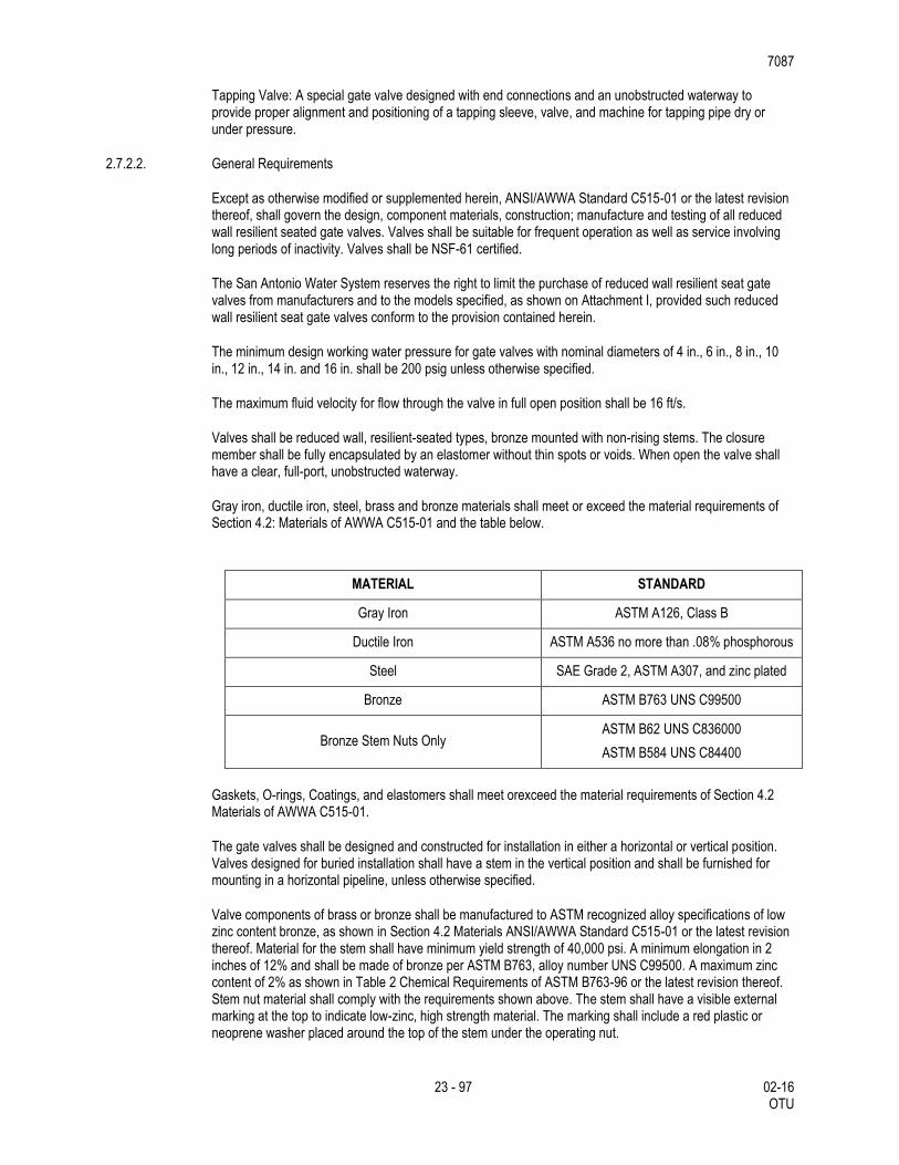
Gray iron, ductile iron, steel, brass and bronze materials shall meet or exceed the material requirements of Section 4.2: Materials of AWWA C515-01 and the table below.
MATERIAL STANDARD
Gray Iron ASTM A126, Class B
Ductile Iron ASTM A536 no more than .08% phosphorous
Steel SAE Grade 2, ASTM A307, and zinc plated
Bronze ASTM B763 UNS C99500
Bronze Stem Nuts Only ASTM B62 UNS C836000
ASTM B584 UNS C84400
Gaskets, O-rings, Coatings, and elastomers shall meet orexceed the material requirements of Section 4.2 Materials of AWWA C515-01.
The gate valves shall be designed and constructed for installation in either a horizontal or vertical position. Valves designed for buried installation shall have a stem in the vertical position and shall be furnished for mounting in a horizontal pipeline, unless otherwise specified.
Valve components of brass or bronze shall be manufactured to ASTM recognized alloy specifications of low zinc content bronze, as shown in Section 4.2 Materials ANSI/AWWA Standard C515-01 or the latest revision thereof. Material for the stem shall have minimum yield strength of 40,000 psi. A minimum elongation in 2 inches of 12% and shall be made of bronze per ASTM B763, alloy number UNS C99500. A maximum zinc content of 2% as shown in Table 2 Chemical Requirements of ASTM B763-96 or the latest revision thereof. Stem nut material shall comply with the requirements shown above. The stem shall have a visible external marking at the top to indicate low-zinc, high strength material. The marking shall include a red plastic or neoprene washer placed around the top of the stem under the operating nut.
7087
24 - 97 02-16 OTU
Valve ends shall be either flanged, tapping valve, mechanical joint, push-on joint or any combination thereof, as specified. All mechanical joint valves shall be supplied with glands, bolts, and gaskets. Valve body bolts and nuts shall meet the strength requirements of ASTM A307 with dimensions conforming to ANSI B18.2.1. The size of the bolt head shall be equal to the size of the nut and shall be stainless steel in accordance with ASTM 276.
All gate valves shall open right (clockwise), unless otherwise specified.
The following parts of the valve shall be made of ductile iron: bonnet and body. Shell thickness shall meet the minimum thickness requirements of Table 1 Minimum Thickness of Body and Bonnet of Section 4.4 Detailed Design of ANSI/AWWA C515 -01. Valves larger than sixteen-inch shall meet the performance requirements of the San Antonio Water System resilient seat reduced gate valve specification.
If glands and bushings are used for the valves shall be made of ASTM B763 bronze UNS C99500. The stem shall be made of cast, forged, or rolled ASTM B763 bronze UNS C99500. The gate may be made of bronze ASTM B763 UNS C99500. Stem seals shall be “O” ring type. The seals shall be designed for dynamic applications. The design shall be such that the seal above the stem collar can be replaced with the valve under full pressure in the fully open position. Materials for the “O” ring packing plate shall be in accordance with Section 4.4.6 Stem Sealing of the ANSI/AWWA C515-01 Standard or the latest revision thereof.
Enclosed and buried valves shall be coated inside and outside with a fusion bonded epoxy having a nominal 8 mils dry film thickness, which meets or exceeds AWWA C550-01 and to the maximum extent possible shall be free of holidays. All coatings in contact with the potable water shall be approved for potable water immersion service per ANSI/NSF Standard 61.
The bidder shall submit with his proposal three sets of certified drawings showing the principal dimensions, general construction and material specification of the valve proposed. The number of turns to open (close) shall be clearly noted in the valve information submitted with the proposal documents. The number of turns to open or close the valve shall be consistent for each valve size for each approved manufacturer.
Valves furnished under this specification shall be supplied from the San Antonio Water System approved manufacturer list.
All gate valve parts shall be designed to withstand the following two pressure requirements, without being structurally damaged. (1) An internal test pressure of twice the rated design working pressure of the valve. In no case shall the pressure be less than 500 psi without any visual deformation. (2) The full rated internal working pressure when the closure member is cycled once from a fully open to a fully closed position against the full rated unbalanced working water pressure. In addition to these pressure requirements, the valve assembly and mechanism shall be capable of withstanding an input torque as follows: 200 ft.- lbs. for a 4-in. nominal diameter. 300 ft.-lbs. for a 6-in. nominal diameter. 300 ft.-lbs. for an 8-in. nominal diameter. 300 ft.-lbs. for a 10-in. nominal diameter. 300 ft.-lbs. for a 12-in. nominal diameter. 400 ft-lbs. for a 14-inch through 20-inch nominal diameter. 600 ft-lbs. for a 24-inch nominal diameter.
Resilient seats shall be applied to the gate and shall seat againsta corrosion resistant surface. The non-metallic seating surface shall be applied in a manner to withstand the action of line fluids and the operation of the sealing gate under long-term service. A metallic surface shall have a corrosion resistance
equivalent to or better than bronze. A non-metallic surface shall be in compliance with ANSI/AWWA C550. The gate must be fully encapsulated by an elastomer without thin spots or voids. Resilient seats shall be bonded. ASTM D429 either method A or method B shall prove the method used for bonding or vulcanizing. For method A, the minimum strength shall not be less than 250 psi. For method B, the peel strength shall be 75 lb./in.
Flanged Ends: The end flanges of flanged valves shall conform to dimensions and drillings of ANSI/AWWA C110/A21.10 or ANSI B16.1, Class 125.
Mechanical Joint Ends: Mechanical joint bell dimensions shall conform to ANSI/AWWA C111/A21.11.
7087
25 - 97 02-16 OTU
Push-on Joints: Push-on joints shall conform to the requirements of ANSI/AWWA C111/A21.11.
Markings shall be cast on the bonnet or body of each valve and shall show the manufacturer’s name or mark, the year the valve casting was made, the size of the valve, the letters "C515", and the designation of working water pressure, for example “200 W”. Markings shall conform to Section 6.1 Marking of ANSI/AWWA C515-01 or latest revision thereof.
The San Antonio Water System may, at no cost to the manufacturer, subject random valves to testing by an independent laboratory for compliance with these standards. Any visible defect or failure to meet the quality standards herein will be grounds for rejecting the entire order and removal of the manufacturer from the attached approval list.
The below qualified product list identifies specified manufacturers that are approved.
The tapping valves shall be configured with a mechanical joint on one end and a tapping flange on the other end. The tapping valves shall be furnished complete with glands, bolts, and gaskets. The tapping valve shall have a clear unobstructed waterway. The seat rings shall be of a large diameter to permit the entry of the full diameter tapping machine cutters. The valve end which mates with the tapping sleeve shall have an alignment lip to fit the recess in the tapping sleeve flange for proper alignment. The lip will be dimensioned in accordance with MSS SP-60 for valves 20-inch nominal pipe size and smaller.
2.7.2.3. Workmanship
All parts of the reduced wall resilient seat gate valve shall be designed and manufactured to the tolerances specified in ANSI/AWWA C515-01 or latest revision thereof and this specification.
All parts of the reduced wall resilient seat gate valve manufactured by a given manufacturer shall be interchangeable with like parts from another reduced wall resilient seat gate valve of the same model and size and by the same manufacturer.
All interchangeable parts shall conform to their required dimensions and shall be free from defects that could prevent proper functioning of the valve.
All castings shall be clean and sound, without defects that will weaken their structure or impair their service. Plugging, welding, or repairing of cosmetic defects is allowed. Repairing of structural defects is not allowed. Repaired valves shall comply with the testing requirements of this specification after repairs have been made. Repairs within the bolt circle of any flange face are not allowed.
The reduced wall resilient seat gate valve shall be well fitted.
Operation of the reduced wall resilient seat gate valve shall be smooth.
All parts shall be free of structural defects.
The reduced wall resilient seat gate valve shall be watertight.
2.7.2.4. Painting
All exterior and interior surfaces of the valve shall be coated with epoxy, N.S.F. 61 certified. The epoxy shall have a nominal dry film thickness of 8 mils, and shall be in accordance with AWWA C550, latest revision.
Coating shall be as close to holiday free as is technologically possible.
2.7.2.5. Testing
7087
26 - 97 02-16 OTU
Hydrostatic Gate Test: Hydrostatic Gate Test shall be performed on the valve in accordance with Section 5.1 Testing of ANSI/AWWA C515-01 or latest revision thereof.
Torque Test: Torque Test for prototype valves shall be performed on the valve in accordance with Section 5.1 Testing of ANSI/AWWA C515-01 or latest revision thereof. Prototype valves larger than sixteen-inch shall meet the torque requirements of section 3q above.
Leakage Test: Leakage Test shall be performed on the valve in accordance with Section 5.1 Testing of ANSI/AWWA C515-01 or latest revision thereof.
Hydrostatic Shell Test: Hydrostatic Shell Test shall be performed on the valve in accordance with Section 5.1 Testing of ANSI/AWWA C515-01 or latest revision thereof. Valves larger than sixteen-inch shall be shell tested at twice the rated working pressure but no less than 500 psi.
Production Test: Production Test shall be performed on the valve in accordance with Section 5.1 Testing of ANSI/AWWA C515-01 or latest revision thereof. This same test shall apply to valves larger than sixteen inch.
Operation Test: Operation Test shall be performed on the valve in accordance with Section 5.1 Testing of ANSI/AWWA C515-01 or latest revision thereof.
Seat Test. Seat Test shall be performed on the valve in accordance with Section 5.1 Testing of ANSI/AWWA C515-01 or latest revision thereof.
An Affidavit of Compliance certifying that all required tests have been performed shall be provided in accordance with Section 6.3 Affidavit of Compliance of ANSI/AWWA C515-01.
The Affidavit of Compliance, the results of ASTM testing procedures and requirements for materials, Manufacturer's Quality Assurance Program, and the records of all tests performed on the valve shall be kept and provided by the supplier/manufacturer in a single hard cover bound notebook with the bid or with the shipping documents and shall be approved by the San Antonio Water System.
2.7.2.6. Quality Assurance
Manufacturers shall have an ASME or I.S.O. 9001 registered commercial quality system. If on receipt of reduced wall resilient seated gate valves they are found to be non-compliant the manufacturer shall replace the defective reduced wall resilient seated gate valves according to reduced wall resilient seated gate valve size with a reduced wall resilient seated gate valve that meets the San Antonio Water System's specifications. The defective reduced wall resilient seated gate valve will be returned to the manufacturer, freight collect, and the manufacturer shall replace the reduced wall resilient seated gate valve, freight prepaid. If San Antonio Water System audits, product inspection and data review in accordance with these specifications determine excessive reduced wall resilient seated gate valve non-compliance, the manufacturer will be subject to removal by the Products Standards Committee. If the reduced wall resilient seated gate valve becomes defective during the manufacturer's specified warranty period a San Antonio Water System quality assurance and manufacturer review will ensue. If the review determines manufacturing non- conformance the manufacturer shall replace the reduced wall resilient seated gate valve according to size with a reduced wall resilient seated gate valve that meets the San Antonio Water System's specifications. The defective reduced wall resilient seated gate valve removed from the field will be returned to the manufacturer, freight collect, and the manufacturer shall replace the reduced wall resilient seated gate valve, freight prepaid. If the non- conformance product amounts are excessive and result in increased product replacement by San Antonio Water System field staff the manufacturer may be subject to time and material charges.
2.7.2.7. References
American National standards Institute and American Water Works Association Standard C509-01 (ANSI/AWWA C509 -01). b) Manufacturers Standardization Society MSS SP-60.
7087
27 - 97 02-16 OTU
2.7.3. Tapping Valves and Tapping Sleeves
This section covers tapping sleeves installed on pipe from 4” and larger nominal pipe diameter.
2.7.3.1. General Requirements
Band shall conform to the minimum OD size ranges and lengths specified in this specification. The flange shall be manufactured in compliance with AWWA C-223.07, Class D ANSI B.16.1 drilling, recessed for tapping valves MSS_SP60. Mechanical Joint tapping sleeve outlet shall meet or exceed all material specifications as listed below and be suitable for use with Standard mechanical joint x mechanical joint resilient wedge gate valves per ANSI/AWWA C-509-94.
2.7.3.2. Tapping sleeves from 4” through 12” nominal pipe diameter shall meet the following minimum requirements:
Entire fitting to be stainless steel type 304 (18-8). The body, lug and gasket armor plate to be in compliance with ASTM A-240. The flange shall be cast stainless steel in compliance with ASTM A-743. The MJ outlet shall be one-piece casting made of stainless steel. The test plug shall be ¾” NTP in compliance with ANSI B2.1 and shall be lubricated or coated to prevent galling. All metal surfaces shall be passivated after fabrication in compliance with ASTM A-380.
The gasket is to provide a 360-sealing surface of such size and shape to provide an adequate compressive force against the pipe after assembly, to affect a positive seal under combinations of joint and gasket tolerances. The materials used shall be vulcanized natural or synthetic rubber with antioxidants and antioziant ingredients to resist set after installation. No reclaimed rubber shall be used. A heavy-gauge-type 304-stainless armor plate shall be vulcanized into the gasket to span the lug area.
The lugs are to be heliarc welded (GMAW) to the shell. Lug shall have a pass-through-bolt design to avoid alignment problems and allow tightening from either side of the main. Bolts shall not be integrally welded to the sleeve. Finger Lug designs are not approved; it is the intent of these specifications to allow tapping sleeve that has a lug design similar to the approved models.
Bolts and nuts shall be type 304 (18-8) stainless steel and lubricated or Teflon coated to prevent galling or seizing. Bent or damaged unit will be rejected.
Quality control procedures shall be employed to insure that the shell, Lug, (4” and larger nominal pipe diameter) armor plate, gasket and related hardware are manufactured to be free of any visible defects. Each unit, after proper installation, shall have a working pressure rating up to 200 psi, and a test pressure of 250 psi.
The sleeve construction shall provide a positive means of preventing gasket cold flow and/or extrusion.
Each sleeve shall be stenciled, coded or marked in a satisfactory manner to identify the size range. The markings shall be permanent type, water resistant that will not smear or become illegible.
2.7.3.3. Tapping Sleeves 16” and larger nominal pipe diameter shall meet the following minimum requirements:
The body shall be in compliance with ASTM A285 Grade C or ASTM A36. Test plug shall be ¾” NPT conforming to ANSI B2.1.
The gasket is to provide a watertight sealing surface of such size and shape to provide an adequate compressive force against the pipe. After assembly, the gasket will insure a positive seal under all combinations of joint and gasket tolerances. Gasket shall be formed from vulcanized natural or synthetic rubber with antioxidants ingredients to resist set after installation. No reclaimed rubber shall be used.
Bolts and nuts shall be type high strength, corrosion resistant, low alloy per AWWA C-111, ANSA A21.11
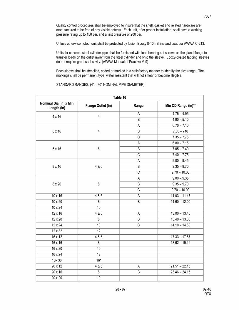
7087
28 - 97 02-16 OTU
Quality control procedures shall be employed to insure that the shell, gasket and related hardware are manufactured to be free of any visible defects. Each unit, after proper installation, shall have a working pressure rating up to 150 psi, and a test pressure of 200 psi.
Unless otherwise noted, unit shall be protected by fusion Epoxy 8-10 mil line and coat per AWWA C-213.
Units for concrete steel cylinder pipe shall be furnished with load bearing set screws on the gland flange to transfer loads on the outlet away from the steel cylinder and onto the sleeve. Epoxy-coated tapping sleeves do not require grout seal cavity. (AWWA Manual of Practive M-9)
Each sleeve shall be stenciled, coded or marked in a satisfactory manner to identify the size range. The markings shall be permanent type, water resistant that will not smear or become illegible.
STANDARD RANGES: (4” – 30” NOMINAL PIPE DIAMETER)
Table 16
Nominal Dia (in) x Min Length (in)
Flange Outlet (in) Range Min OD Range (in)**
4 x 16 4 A 4.75 – 4.95
B 4.90 – 5.10
6 x 16 4
A 6.70 – 7.10
B 7.00 – 740
C 7.35 – 7.75
6 x 16 6
A 6.80 – 7.15
B 7.05 – 7.40
C 7.40 – 7.75
8 x 16 4 & 6
A 9.00 – 9.45
B 9.35 – 9.70
C 9.70 – 10.00
8 x 20 8
A 9.00 – 9.35
B 9.35 – 9.70
C 9.70 – 10.00
10 x 16 4 & 6 A 11.03 – 11.47
10 x 20 8 B 11.60 – 12.00
10 x 24 10
12 x 16 4 & 6 A 13.00 – 13.40
12 x 20 8 B 13.40 – 13.80
12 x 24 10 C 14.10 – 14.50
12 x 32 12
16 x 12 4 & 6 17.33 – 17.87
16 x 16 8 18.62 – 19.19
16 x 20 10
16 x 24 12
16x 36 16*
20 x 12 4 & 6 A 21.51 – 22.15
20 x 16 8 B 23.46 – 24.16
20 x 20 10
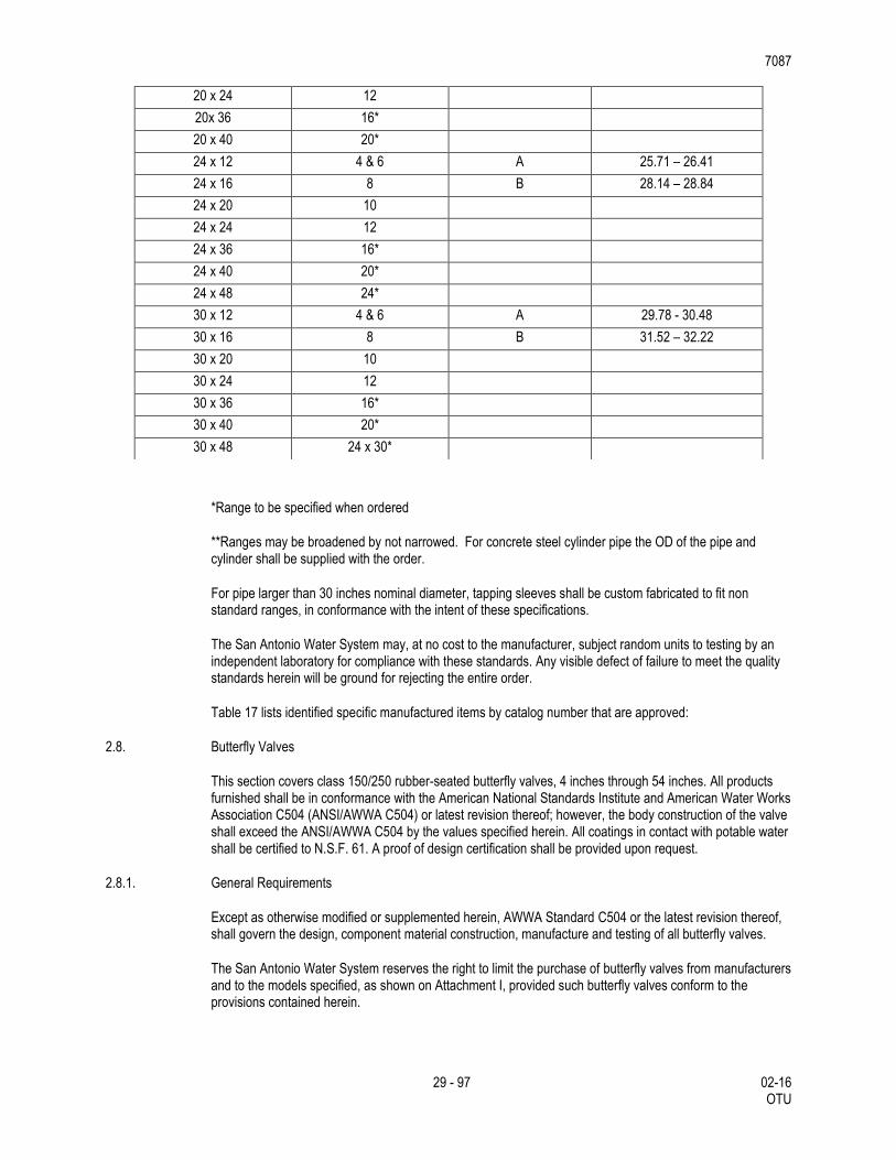
7087
29 - 97 02-16 OTU
*Range to be specified when ordered
**Ranges may be broadened by not narrowed. For concrete steel cylinder pipe the OD of the pipe and cylinder shall be supplied with the order.
For pipe larger than 30 inches nominal diameter, tapping sleeves shall be custom fabricated to fit non standard ranges, in conformance with the intent of these specifications.
The San Antonio Water System may, at no cost to the manufacturer, subject random units to testing by an independent laboratory for compliance with these standards. Any visible defect of failure to meet the quality standards herein will be ground for rejecting the entire order.
Table 17 lists identified specific manufactured items by catalog number that are approved:
2.8. Butterfly Valves
This section covers class 150/250 rubber-seated butterfly valves, 4 inches through 54 inches. All products furnished shall be in conformance with the American National Standards Institute and American Water Works Association C504 (ANSI/AWWA C504) or latest revision thereof; however, the body construction of the valve shall exceed the ANSI/AWWA C504 by the values specified herein. All coatings in contact with potable water shall be certified to N.S.F. 61. A proof of design certification shall be provided upon request.
2.8.1. General Requirements
Except as otherwise modified or supplemented herein, AWWA Standard C504 or the latest revision thereof, shall govern the design, component material construction, manufacture and testing of all butterfly valves.
The San Antonio Water System reserves the right to limit the purchase of butterfly valves from manufacturers and to the models specified, as shown on Attachment I, provided such butterfly valves conform to the provisions contained herein.
20 x 24 12
20x 36 16*
20 x 40 20*
24 x 12 4 & 6 A 25.71 – 26.41
24 x 16 8 B 28.14 – 28.84
24 x 20 10
24 x 24 12
24 x 36 16*
24 x 40 20*
24 x 48 24*
30 x 12 4 & 6 A 29.78 - 30.48
30 x 16 8 B 31.52 – 32.22
30 x 20 10
30 x 24 12
30 x 36 16*
30 x 40 20*
30 x 48 24 x 30*
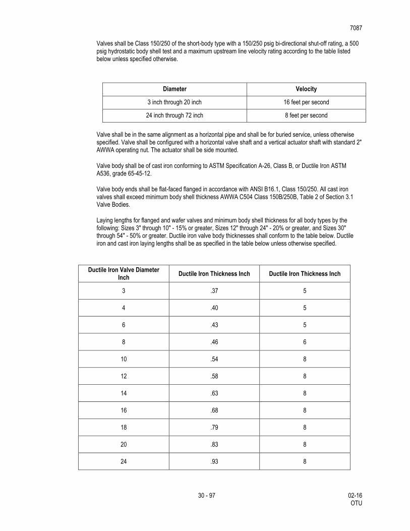
7087
30 - 97 02-16 OTU
Valves shall be Class 150/250 of the short-body type with a 150/250 psig bi-directional shut-off rating, a 500 psig hydrostatic body shell test and a maximum upstream line velocity rating according to the table listed below unless specified otherwise.
Diameter Velocity
3 inch through 20 inch 16 feet per second
24 inch through 72 inch 8 feet per second
Valve shall be in the same alignment as a horizontal pipe and shall be for buried service, unless otherwise specified. Valve shall be configured with a horizontal valve shaft and a vertical actuator shaft with standard 2" AWWA operating nut. The actuator shall be side mounted.
Valve body shall be of cast iron conforming to ASTM Specification A-26, Class B, or Ductile Iron ASTM A536, grade 65-45-12.
Valve body ends shall be flat-faced flanged in accordance with ANSI B16.1, Class 150/250. All cast iron valves shall exceed minimum body shell thickness AWWA C504 Class 150B/250B, Table 2 of Section 3.1 Valve Bodies.
Laying lengths for flanged and wafer valves and minimum body shell thickness for all body types by the following: Sizes 3" through 10" - 15% or greater, Sizes 12" through 24" - 20% or greater, and Sizes 30" through 54" - 50% or greater. Ductile iron valve body thicknesses shall conform to the table below. Ductile iron and cast iron laying lengths shall be as specified in the table below unless otherwise specified.
Ductile Iron Valve Diameter Inch
Ductile Iron Thickness Inch Ductile Iron Thickness Inch
3 .37 5
4 .40 5
6 .43 5
8 .46 6
10 .54 8
12 .58 8
14 .63 8
16 .68 8
18 .79 8
20 .83 8
24 .93 8
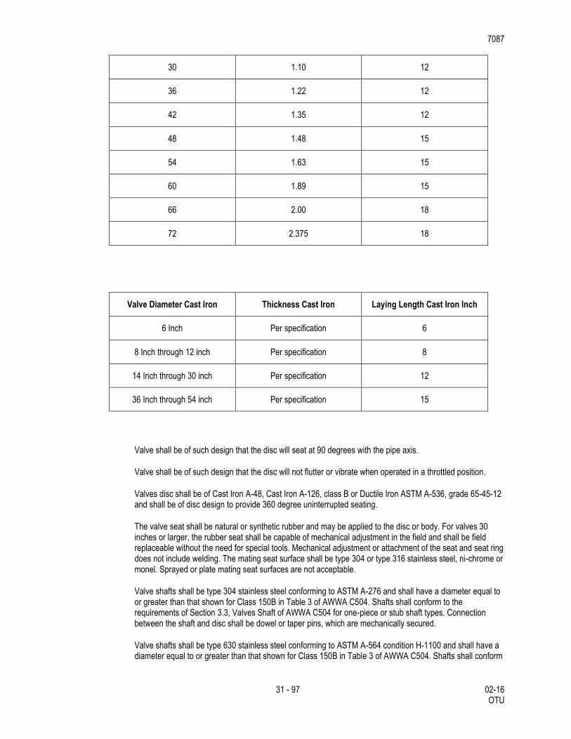
7087
31 - 97 02-16 OTU
30 1.10 12
36 1.22 12
42 1.35 12
48 1.48 15
54 1.63 15
60 1.89 15
66 2.00 18
72 2.375 18
Valve Diameter Cast Iron Thickness Cast Iron Laying Length Cast Iron Inch
6 Inch Per specification 6
8 Inch through 12 inch Per specification 8
14 Inch through 30 inch Per specification 12
36 Inch through 54 inch Per specification 15
Valve shall be of such design that the disc will seat at 90 degrees with the pipe axis.
Valve shall be of such design that the disc will not flutter or vibrate when operated in a throttled position.
Valves disc shall be of Cast Iron A-48, Cast Iron A-126, class B or Ductile Iron ASTM A-536, grade 65-45-12 and shall be of disc design to provide 360 degree uninterrupted seating.
The valve seat shall be natural or synthetic rubber and may be applied to the disc or body. For valves 30 inches or larger, the rubber seat shall be capable of mechanical adjustment in the field and shall be field replaceable without the need for special tools. Mechanical adjustment or attachment of the seat and seat ring does not include welding. The mating seat surface shall be type 304 or type 316 stainless steel, ni-chrome or monel. Sprayed or plate mating seat surfaces are not acceptable.
Valve shafts shall be type 304 stainless steel conforming to ASTM A-276 and shall have a diameter equal to or greater than that shown for Class 150B in Table 3 of AWWA C504. Shafts shall conform to the requirements of Section 3.3, Valves Shaft of AWWA C504 for one-piece or stub shaft types. Connection between the shaft and disc shall be dowel or taper pins, which are mechanically secured.
Valve shafts shall be type 630 stainless steel conforming to ASTM A-564 condition H-1100 and shall have a diameter equal to or greater than that shown for Class 150B in Table 3 of AWWA C504. Shafts shall conform
7087
32 - 97 02-16 OTU
to the requirements of Section 3.3, Valves Shaft of AWWA C504 for one-piece or stub shaft types. Connection between the shaft and disc shall be dowel, taper pins, or torque plugs, which are mechanically secured.
The valve assembly shall be furnished with a factory-set, non-adjustable disc shaft thrust bearing that insures the valve disc is centered within the valve body seat at all times.
Valve shaft bearings shall be permanent, self-lubricated bearings which provide continuous, low-friction maintenance-free operation. Shaft bearing shall be contained in integral hubs of the valve body.
Valve shaft seal shall consist of O-ring, V-type, or U-cup type packing where the shaft projects through the valve body for the actuator connection.
The valve shall be provided with a fully enclosed, permanently lubricated actuator of the traveling nut or worm gear design. The actuator shall be connected to the valve shaft by means of a key and keyway connection.
All actuators shall have adjustable, mechanical stop limits in accordance with AWWA C504 Section 3.8.2. All 4" - 54" valve actuators shall be capable of withstanding 450 ft-lbs of input torque against the open or closed stops without damage.
Valves for below ground applications shall be provided with an AWWA wrench nut. The wrench nut shall have an arrow cast thereon, indicating the direction on of opening. The wrench nut shall be suitably fastened to the actuator input shaft. If the shaft is smooth, the wrench nut shall be fastened to the input shaft by means of a minimum 5/16" diameter steel pin passing entirely through the shaft and the wrench nut. Key with keyway will be acceptable. If the shaft is splined, the wrench nut shall be formed to fit the splined shaft. The actuator shall be designed to produce the specified torque with a maximum input of 150 ft-lbs applied to the wrench nut.
Valves for aboveground applications shall be provided with a handwheel. The handwheel shall have an arrow thereon, indicating the direction of the opening. The handwheel shall be suitably fastened to the actuator input shaft. Actuators equipped with handwheels shall be designed to produce the specified torque with a maximum pull of 80 pounds of the handwheel rim.
The requirement for either wrench nut or handwheel and the direction of opening will be specified on each purchase order.
The bidder shall submit with his proposal three sets of certified drawings showing the principal dimensions, general construction and material specification of the valve proposed. The number of turns to open (close) shall be clearly noted in the valve information submitted with the proposal documents.
The supplier/manufacturer shall provide Affidavit of Compliance with applicable sections of AWWA C504 and/or San Antonio Water System Specification 21-05 to include the following: Results of ASTM testing procedures and requirements for materials will be provided to the Owner upon request, Manufacturer's Quality Assurance Program, leak-tightness testing and proof of design testing of representative actuators in accordance with AWWA C504 Section 3.8.5.2 as modified herein (450 ft.-lbs.). Compliance assurance will be required in accordance with AWWA C504 Section 5.1.2, Affidavits. Results of performance tests, proof of design test, AWWA C504 Section 5.2.4, hydrostatic test, leakage test, and Affidavit of Compliance shall be provided with the bid or with the shipping documents and shall be approved by the San Antonio Water System.
Valves furnished under this specification shall be supplied by the approved manufacturer list.
2.8.2. Workmanship
7087
33 - 97 02-16 OTU
All parts of the butterfly valve shall be designed and manufactured to the tolerances specified in ANSI/AWWA C509 or latest revision thereof and this specification.
All parts of the butterfly valve manufactured by a given manufacturer shall be interchangeable with like parts from another butterfly valve of the same model and size and by the same manufacturer.
2.8.3. Painting
All interior and exterior ferrous surfaces of the valve, including the disc, shall be coated with epoxy, N.S.F. 61 certified or fusion bonded epoxy, N.S.F.61 certified. The epoxy (or fusion bonded epoxy) shall have a nominal thickness of 8 mils, and shall be in accordance with AWWA C550, latest revision.
Coating shall be as close to holiday free as is technologically possible.
2.8.4. Testing and Inspection
Performance Tests: Performance tests shall be performed on each valve in accordance with Section 5.2.1 Testing of ANSI/AWWA C504 or latest revision thereof.
Leakage Tests: Leakage tests shall be performed on each valve in accordance with Section 5.2.2 Testing of ANSI/AWWA C504 or latest revision thereof.
Hydrostatic Tests: Hydrostatic tests shall be performed on each valve in accordance with Section 5.2.3 Testing of ANSI/AWWA C504 or latest revision thereof.
Proof-of-Design Tests: Proof-of-Design tests shall be performed on each valve in accordance with Section 5.2.4 Testing of ANSI/AWWA C504 or latest revision thereof.
An Affidavit of Compliance certifying that all required tests have been performed shall be provided.
The Affidavit of Compliance and the records of all tests performed on the valves shall be kept and provided in a single hard cover bound notebook.
2.8.5. Quality Assurance
Manufacturers shall have an ASME or I.S.O. 9001 registered commercial quality system. If on receipt of butterfly valves they are found to be noncompliant the manufacturer shall replace the defective butterfly valves according to butterfly valve size with a butterfly valve that meets the San Antonio Water System's specifications. The defective butterfly valves will be returned to the manufacturer, freight collect, and the manufacturer shall replace the butterfly valve, freight prepaid.
If San Antonio Water System audits, product inspection and performance data review in accordance with these specifications determine excessive butterfly valve non-compliance, the manufacturer will be subject to removal by the Products Standards Committee. If the butterfly valve becomes defective during the Manufacturer's specified warranty period a San Antonio Water System quality assurance and manufacturer review will ensue. If the review determines manufacturing non-conformance the manufacturer shall replace the butterfly valve according to size with a butterfly valve that meets the San Antonio Water System's specifications. The defective butterfly valve removed from the field will be returned to the manufacturer, freight collect, and the manufacturer shall replace the butterfly valve, freight prepaid. If the nonconformance product amounts are excessive and result in increased product replacement by San Antonio Water System field staff the manufacturer may be subject to time and material charges.
2.8.6. References
American National Standards Institute and American Water Works Association Standard C504 (ANSI/AWWA C504).
7087
34 - 97 02-16 OTU
2.9. Valve Boxes
This section covers cast-iron valve box assemblies.
2.9.1. General Requirements:
Each valve box assembly shall be of cast-iron and shall consist of a base, top section, and lid as shown on the plans on San Antonio Water System Standard Drawing No.DA-56-00.
Valve boxes shall be of a single size with a nominal diameter of 6 inches.
The valve box lid shall be labeled "water" and shall be so designed so that it will remain firmly seated in place when subjected to vehicular traffic.
The valve box assembly shall be of sufficient toughness and strength to withstand impact loads and shock resulting from vehicular traffic.
The valve box assembly shall be coated with a standard bituminous coating of either coal tar or asphalt basic applied to all inside and outside surfaces.
2.10. Meter Boxes
This section covers meter boxes for 5/8”, ¾”, 1”, 1-1/2”, and 2” meters.
2.10.1. General Requirements
For non-traffic bearing locations, the meter box assembly for 5/8" through 1" meters shall be made from 100% high-quality recycling plastic. The meter box and lid shall be black and constructed out of modified polyethylene material for maximum durability and corrosion resistance. The black material is for maximum UV protection. The black material shall be uniform throughout the meter box and lid for maximum longevity and not have a foaming agent that creates air pockets within the plastic wall. The body and lid shall withstand 20,500 lbs loading in a non-deliberate and incidental traffic.
For traffic bearing locations, the meter box assembly for 5/8" through 2" meters shall consist of a cast-iron rectangular box and a steel checkered plate rectangular cover with raised lug pattern as shown on the plans in San Antonio Water System Standard Drawing No. DA-11-01 (Meter size: 5/8” thru 2”).
2.10.2. Specific Requirements
2.10.2.1. Plastic Lid is to have the following:
“Water Meter” and “SAWS” molded into the lid
Seat securely and evenly inside the meter box and shall not overlap the top edge of the meter box
“Overlap” and securely and evenly on the existing SAWS cast iron meter box with like dimensions.
A diamond pattern for skid resistance and an AMR Slide Mount molded into the lid on the underneath side and off center for placement for an AMR transponder to help in the protection of the radio antenna.
A brass worn gear lock that will secure the existing SAWS cast iron meter box of like dimensions and secure the plastic meter box. See detail on plans.
A molded receptacle for placement of SAWS key.
7087
35 - 97 02-16 OTU
One (1) piece of ½” rebar secured in lid. See detail.
2.10.2.2. Plastic body is to have the following:
A crush resistant ribbing along the outside of box.
A flange around the top opening to help prevent setting and aide in adjustment to grade.
Designed to accommodate all plastic lids.
2.10.2.3. Cast Iron Rectangular box for Traffic Bearing Locations shall have the following:
Ultimate tensile strength of 25,000 psi and shall not be brittle.
“As cast” clean smooth surface and be free from internal porosity, castings that are made smooth by grinding will not be considered.
Be dipped in a coal tar at a temperature of 350 degrees and the metal shall be at a temperature of 300 degrees prior to dipping. The casting shall be dipped and cured independently and the coating shall have ceased to be "tacky" within 72 hours after dipping.
The steel checkered plate rectangular cover is to be hot dip galvanized after fabrication.
2.10.3. Quality Assurance:
If on receipt of meter box(s) or lid(s) they are found to be non-compliant, the manufacturer shall replace the defective box(s) or lid(s) with a replacement that meets the San Antonio Water System’s specifications, at no charge to San Antonio Water System. Any visible defect or failure to meet the quality standards herein will be ground for rejecting the entire order.
Product that is non-compliant will be returned to the manufacturer, freight collect and the manufacturer will replace the defective product, freight prepaid within thirty (30) days from receipt of the defective product.
2.11. Fire Hydrants
This section covers post-type, dry-barrel fire hydrants with compression shut off (opening against pressure) or gate shutoff for use in water supply service in all climates, including those where freezing occurs. All products furnished shall conform to the American National Standards Institute and American Water Works Association C502-05 Standard (ANSI/AWWA C502-05) or latest revision thereof and shall be UL approved.
Definitions:
All definitions are defined according to ANSI/AWWA C502-05.
Cosmetic Defect: A blemish that has no effect on the ability of a component to meet the structural design and production test requirements of this standard. Should the blemish or the activity of plugging, welding, grinding, or repairing such blemishes cause the component to fail these requirements, and then the blemish shall be considered a structural defect.
Structural Defect: A flaw that causes a component to fail the structural design or test requirements of this standard. This includes but is not limited to imperfections that result in leakage through the walls of a casting, failure to meet minimum wall thickness requirements, or failure to meet production tests.
Bury: The length of bury is the distance measured to the nearest ½ ft. from the bottom of the connecting pipe to the ground line of the hydrant.
7087
36 - 97 02-16 OTU
2.11.1. General Requirements
The San Antonio Water System reserves the right to limit the purchase of fire hydrants from manufacturers and to the models specified, as shown on Table 18, provided such fire hydrants conform to the provision contained herein.
Each hydrant shall be designed for a minimum working pressure of 200 psig.
All parts of the hydrant shall be designed to withstand, without being functionally impaired or structurally damaged, a hydrostatic test of not less than 400 psig or twice the rated working pressure, whichever is greater, with the hydrant completely assembled and pressurized as follows:
With the nozzle caps in place, the main valve open, the hydrant inlet capped, and the test pressure
applied to the interior of the hydrant.
With the main valve closed, the hydrant inlet capped, and the test pressure applied at the hydrant inlet.
The design safety factor of the operating mechanism shall not be less than 5 and shall be based on the
foot-pounds of torque required for the closing and opening of the hydrant at a working pressure of 200
psig. Hydrants shall be functional and capable of being opened or closed without difficulty following an
application of an operating torque of 200 lbf-ft at the operating nut in the opening direction with the
hydrant fully opened and the closing direction with the hydrant fully closed. The torque requirements
apply only to hydrants of 5-foot bury or less.
The length of bury shall be as specified but not less than 4 feet.
The fire hydrant shall have 2 hose nozzles and 1 pumper nozzle.
The nominal inside diameter of the hose nozzle shall be 2 ½ inches.
The nominal inside diameter for the pumper nozzle shall be 4 inches.
The outlet-nozzle threads are to conform to the National Fire Protection Association (NFPA) 2003, Standard for Fire Hose Connections.
The nominal diameter of the main valve opening shall be 5 ¼ inches.
The hydrant shoe shall be provided with a 6 inches mechanical joint connection to fit the connecting pipe.
The fire hydrant shall open right (clockwise).
The color of the finish paint above the ground line shall be aluminum; however, fire hydrants for private use shall be painted red.
The fire hydrant shall have a non-rising stem.
No more than one 6" stem extension shall be provided if required to make the base of the fire hydrant grade level.
The bonnet section shall be designed so all bearing surfaces and stem threads are sealed in a lubricant reservoir. If oil is used as a lubricant, the reservoir shall be designed to allow for easy filling through a fitting or plug. Where grease is used as a lubricant, the reservoir will be sealed. The reservoir will be adequately sealed with "O" rings or other suitable sealing system approved by the San Antonio Water System.
The fire hydrant shall have a safety flange or breakaway flange at the ground line as stipulated in Section 3.1 General Design of ANSI/AWWA C-502-05 or latest revision thereof.
7087
37 - 97 02-16 OTU
Fire hydrant nozzle cap chains shall be required and shall be attached permanently to the fire hydrant as stipulated in Section 3.2 Detailed Design of ANSI/AWWA C-502-05 or latest revision thereof.
Parts that require lubrication and come into contact with water shall be lubricated with a non-toxic food grade lubricant that does not pose a health hazard to the public if consumed.
2.11.2. Workmanship
All foundry and machine work shall be performed in accordance with good standard practice for the class of work involved and in conformance with accepted drawings, if required. When assembled, hydrants manufactured in accordance with this specification shall be well fitted and shall operate smoothly. The body and shaft shall be watertight.
All parts shall conform to the required dimensions and shall be free from defects that could prevent proper functioning of the hydrant.
All castings shall be clean and sound without defects that will weaken their structure or impair their service.
2.11.3. Paint
The exterior surface of the hydrant shall be coated with a coating that shall meet or exceed the requirements of Federal Specification TT-C-494b. A second coat of water based or oil based enamel paint aluminum in color will then be applied from the top of the hydrant to a point 18 to 20 inches below the center line of the pumper nozzle or down to the traffic safety flange connection at the ground line.
All interior surfaces, machined surfaces, such as the threaded portion of the stem or stem nut, which must fit closely with the adjacent parts, shall be coated with a coating that shall meet or exceed Federal Specification TT-C-494b. Stem surfaces contained within a lubricant reservoir and not in contact with potable water may be free of coating.
The interior and exterior of the hydrant shoe shall be coated with a fusion-bonded epoxy having a nominal dry film thickness of 8 mils, conforming to ANSI/AWWA C-550-05, and certified to NSF 61.
Coating shall be as close to holiday free as is technologically possible.
2.11.4. Testing and Inspection
Each assembled hydrant shall be subjected to two shop tests under a hydrostatic pressure of 400 psig or twice the rated working pressure, whichever is greater. One test shall be made with the entire interior of the hydrant under pressure and another test made with the main valve closed and the base under pressure from the inlet side. Under the test procedure, there shall be no leakage through the main valve or seals or through the castings or the joints of the assembled hydrant. Under the test conditions, the leakage through the drain valves shall not exceed 5 fl oz/min. Other leakage or other imperfections found in either test shall be corrected or the hydrant retested. The tests shall be conducted for a sufficient time to allow a check of all points of possible leakage and for a minimum of 30 seconds after all air has been exhausted.
Each assembled hydrant shall be operated through a full open-close cycle when not under pressure. The torque required for performing this operation shall not exceed 200 lbf-ft.
All fire hydrant tests and inspections shall conform to ANSI/AWWA C-502 Section 5.1 Production Testing, ANSI/AWWA C-502 Section 5.2 Prototype Testing, and ANSI/AWWA C-502-05 Section 5.3 Inspection and Rejection.
The manufacturer shall provide an Affidavit of Compliance conforming to Section 1.7 Affidavit of Compliance of ANSI/AWWA C-502-05 or latest revision thereof.
7087
38 - 97 02-16 OTU
2.11.5. Quality Assurance
Manufacturers shall have an ASME or I.S.O. 9001 registered commercial quality system or is in the process of achieving this certification by June 2001. Noncompliance to this registered commercial quality system requirement by June 2001 will result in removal of the manufacturer's product from Table 15 of this specification. If on receipt of fire hydrants they are found to be noncompliant the manufacturer shall replace the defective fire hydrants according to fire hydrant size with a fire hydrant that meets the San Antonio Water System's specifications. The defective fire hydrants will be returned to the manufacturer, freight collect, and the manufacturer shall replace the fire hydrant, freight prepaid. If San Antonio Water System audits, product inspection and performance data review in accordance with these specifications determine excessive fire hydrant non-compliance, the manufacturer will be subject to removal by the Products Standards Committee. If the fire hydrant becomes defective during the manufacturer's specified warranty period a San Antonio Water System quality assurance and manufacturer review will ensue. If the review determines manufacturing nonconformance the manufacturer shall replace the fire hydrant according to size with a fire hydrant that meets the San Antonio Water System's specifications. The defective fire hydrant removed from the field will be returned to the manufacturer, freight collect, and the manufacturer shall replace the fire hydrant, freight prepaid. If the non-conformance product amounts are excessive and result in increased product replacement by San Antonio Water System field staff the manufacturer may be subject to time and material charges.
2.11.6. References
American National Standards Institute and American Water Works Association Standard C-502-05 (ANSI/AWWA C-502-05).
American National Standards Institute and American Water Works Association Standard C-550-05 (ANSI/AWWA C-550-05).
2.12. Polyethylene Wrapping Material
This section covers polyethylene-wrapping material for use in encapsulating ductile and cast iron pipe.
2.12.1. General Requirements
Polyethylene wrapping for ductile and cast iron water mains is to consist of a 4 mil tubular section of cross-laminated high-density polyethylene, which has a high dielectric and tensile strength, for use in insulating cast-iron and ductile-iron pipe from the electrolytic action encountered in highly active soils. All iron pipe, fittings, and accessories shall be wrapped with edges overlapped and taped securely with duct tape to provide a continuous wrap to prevent contact between the pipe and the surrounding backfill. Repair all punctures with duct tape to restore the continuous protection before backfilling.
Polyethylene wrapping is to consist of opaque cross-laminated high-density polyethylene sheet continuously thermally bonded to form a tubular section. The tubes may be supplied in bulk length on rolls or in individual pre-cut lengths. See Table 21 for size and length chart, in accordance with AWWA C-105 (Table 1) for minimum requirements. When supplied in specific pipe lengths, the tubes are to contain a minimum of 4-ft. over the actual pipe length to allow for overlap.
The polyvinyl sheet of film for the tubular wrapping is to be of virgin resins meeting raw and physical properties of ASTM D-1248 and AWWA C-105, latest edition. The material is to be 4 mil cross-laminated high-density polyethylene of uniform film thickness and be free of imperfections such as pin holes, etc., after being thermally seamed into tubular form. The finished product will have a nominal thickness of 4 mils, with tolerances of minus ten percent.
The material is to have no volatile constituents, the loss of which may affect ductility. The material is also to have the following properties:
Mechanical: The polyethylene film is to have a tensile strength per latest ASTM D-882 test, of 6300 psi
min. The film is to have an elongation of not less than 100% of the test strip per latest ASTM D-882
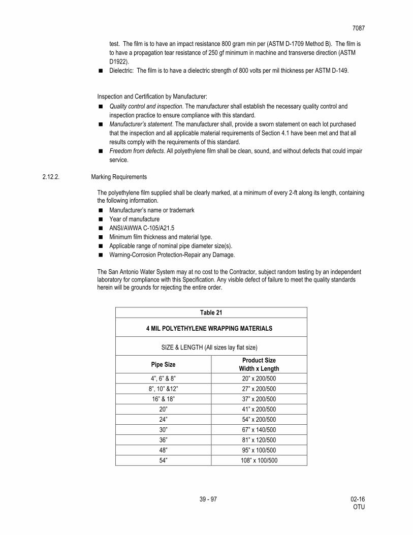
7087
39 - 97 02-16 OTU
test. The film is to have an impact resistance 800 gram min per (ASTM D-1709 Method B). The film is
to have a propagation tear resistance of 250 gf minimum in machine and transverse direction (ASTM
D1922).
Dielectric: The film is to have a dielectric strength of 800 volts per mil thickness per ASTM D-149.
Inspection and Certification by Manufacturer:
Quality control and inspection. The manufacturer shall establish the necessary quality control and
inspection practice to ensure compliance with this standard.
Manufacturer’s statement. The manufacturer shall, provide a sworn statement on each lot purchased
that the inspection and all applicable material requirements of Section 4.1 have been met and that all
results comply with the requirements of this standard.
Freedom from defects. All polyethylene film shall be clean, sound, and without defects that could impair
service.
2.12.2. Marking Requirements
The polyethylene film supplied shall be clearly marked, at a minimum of every 2-ft along its length, containing the following information.
Manufacturer’s name or trademark
Year of manufacture
ANSI/AWWA C-105/A21.5
Minimum film thickness and material type.
Applicable range of nominal pipe diameter size(s).
Warning-Corrosion Protection-Repair any Damage.
The San Antonio Water System may at no cost to the Contractor, subject random testing by an independent laboratory for compliance with this Specification. Any visible defect of failure to meet the quality standards herein will be grounds for rejecting the entire order.
Table 21
4 MIL POLYETHYLENE WRAPPING MATERIALS
SIZE & LENGTH (All sizes lay flat size)
Pipe Size Product Size
Width x Length
4”, 6” & 8” 20” x 200/500
8”, 10” &12” 27” x 200/500
16” & 18” 37” x 200/500
20” 41” x 200/500
24” 54” x 200/500
30” 67” x 140/500
36” 81” x 120/500
48” 95” x 100/500
54” 108” x 100/500
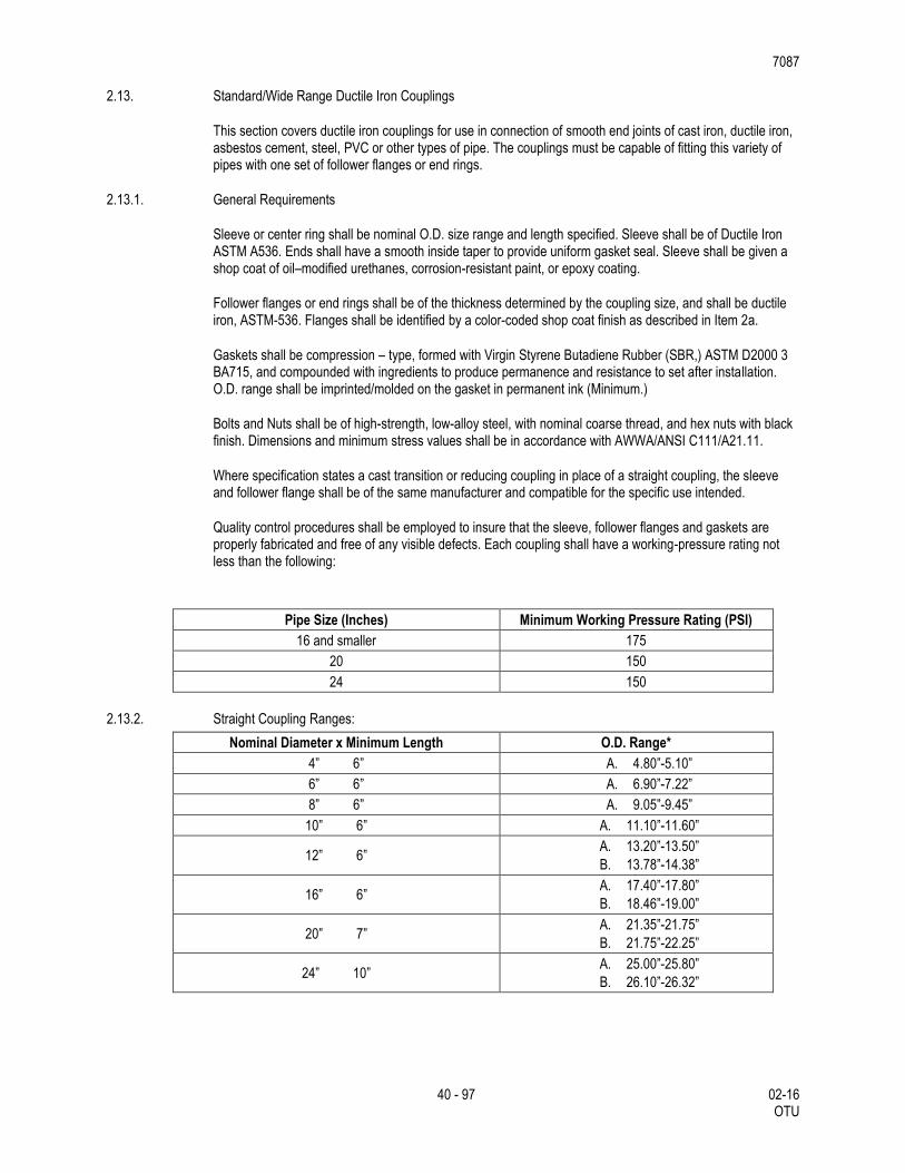
7087
40 - 97 02-16 OTU
2.13. Standard/Wide Range Ductile Iron Couplings
This section covers ductile iron couplings for use in connection of smooth end joints of cast iron, ductile iron, asbestos cement, steel, PVC or other types of pipe. The couplings must be capable of fitting this variety of pipes with one set of follower flanges or end rings.
2.13.1. General Requirements
Sleeve or center ring shall be nominal O.D. size range and length specified. Sleeve shall be of Ductile Iron ASTM A536. Ends shall have a smooth inside taper to provide uniform gasket seal. Sleeve shall be given a shop coat of oil–modified urethanes, corrosion-resistant paint, or epoxy coating.
Follower flanges or end rings shall be of the thickness determined by the coupling size, and shall be ductile iron, ASTM-536. Flanges shall be identified by a color-coded shop coat finish as described in Item 2a.
Gaskets shall be compression – type, formed with Virgin Styrene Butadiene Rubber (SBR,) ASTM D2000 3 BA715, and compounded with ingredients to produce permanence and resistance to set after installation. O.D. range shall be imprinted/molded on the gasket in permanent ink (Minimum.)
Bolts and Nuts shall be of high-strength, low-alloy steel, with nominal coarse thread, and hex nuts with black finish. Dimensions and minimum stress values shall be in accordance with AWWA/ANSI C111/A21.11.
Where specification states a cast transition or reducing coupling in place of a straight coupling, the sleeve and follower flange shall be of the same manufacturer and compatible for the specific use intended.
Quality control procedures shall be employed to insure that the sleeve, follower flanges and gaskets are properly fabricated and free of any visible defects. Each coupling shall have a working-pressure rating not less than the following:
Pipe Size (Inches) Minimum Working Pressure Rating (PSI)
16 and smaller 175
20 150
24 150
2.13.2. Straight Coupling Ranges:
Nominal Diameter x Minimum Length O.D. Range*
4” 6” A. 4.80”-5.10”
6” 6” A. 6.90”-7.22”
8” 6” A. 9.05”-9.45”
10” 6” A. 11.10”-11.60”
12” 6” A. 13.20”-13.50”
B. 13.78”-14.38”
16” 6” A. 17.40”-17.80”
B. 18.46”-19.00”
20” 7” A. 21.35”-21.75”
B. 21.75”-22.25”
24” 10” A. 25.00”-25.80”
B. 26.10”-26.32”
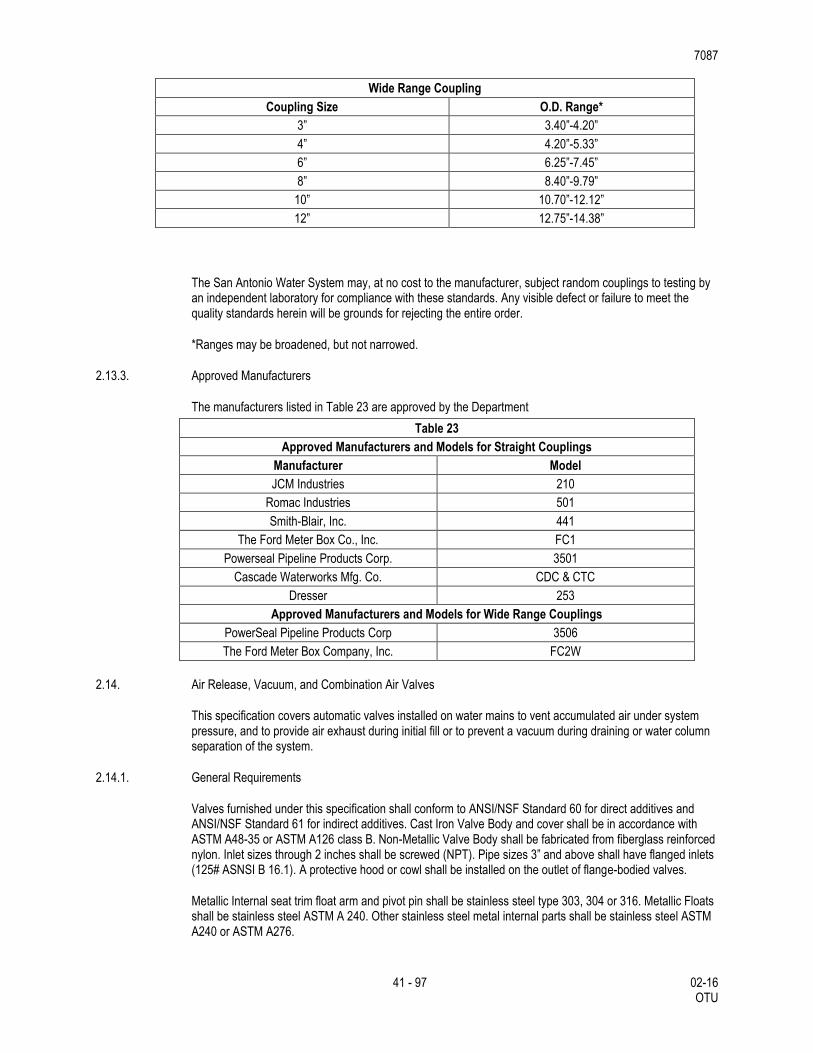
7087
41 - 97 02-16 OTU
Wide Range Coupling
Coupling Size O.D. Range*
3” 3.40”-4.20”
4” 4.20”-5.33”
6” 6.25”-7.45”
8” 8.40”-9.79”
10” 10.70”-12.12”
12” 12.75”-14.38”
The San Antonio Water System may, at no cost to the manufacturer, subject random couplings to testing by an independent laboratory for compliance with these standards. Any visible defect or failure to meet the quality standards herein will be grounds for rejecting the entire order.
*Ranges may be broadened, but not narrowed.
2.13.3. Approved Manufacturers
The manufacturers listed in Table 23 are approved by the Department
Table 23
Approved Manufacturers and Models for Straight Couplings
Manufacturer Model
JCM Industries 210
Romac Industries 501
Smith-Blair, Inc. 441
The Ford Meter Box Co., Inc. FC1
Powerseal Pipeline Products Corp. 3501
Cascade Waterworks Mfg. Co. CDC & CTC
Dresser 253
Approved Manufacturers and Models for Wide Range Couplings
PowerSeal Pipeline Products Corp 3506
The Ford Meter Box Company, Inc. FC2W
2.14. Air Release, Vacuum, and Combination Air Valves
This specification covers automatic valves installed on water mains to vent accumulated air under system pressure, and to provide air exhaust during initial fill or to prevent a vacuum during draining or water column separation of the system.
2.14.1. General Requirements
Valves furnished under this specification shall conform to ANSI/NSF Standard 60 for direct additives and ANSI/NSF Standard 61 for indirect additives. Cast Iron Valve Body and cover shall be in accordance with ASTM A48-35 or ASTM A126 class B. Non-Metallic Valve Body shall be fabricated from fiberglass reinforced nylon. Inlet sizes through 2 inches shall be screwed (NPT). Pipe sizes 3” and above shall have flanged inlets (125# ASNSI B 16.1). A protective hood or cowl shall be installed on the outlet of flange-bodied valves.
Metallic Internal seat trim float arm and pivot pin shall be stainless steel type 303, 304 or 316. Metallic Floats shall be stainless steel ASTM A 240. Other stainless steel metal internal parts shall be stainless steel ASTM A240 or ASTM A276.
7087
42 - 97 02-16 OTU
Non-metallic floats shall be foamed polyethylene with stainless steel type 316 fasteners.
Valves requiring Internal seats or orifice buttons shall be Buna-N rubber compounded for water service. For valves requiring cover gaskets, the cover gasket shall be composition type, equal to Armstrong CS-231, Garlock 3000, or Lexide NK-511. If an O-Ring is used to seal the cover, it shall be on NSF 61 certified rubber. Cover bolts shall be alloy steel. Rolling seals shall be furnished for non-metallic valves 2” and below.
Valve body shall have a test pressure rating of 300 psi and working pressure rating of 150 psi.
All components in contact with potable water must be “lead free” and marked by stamping, etching, or casting “NL” in the main body.
2.14.2. General Operation Requirements
The air release valve shall be designed to vent accumulated air automatically. The outlet orifice shall be properly sized to facilitate valve operation at pressures up to 150 psi. The air release valve shall be simple-lever, compound-lever, ball and orifice or rolling seal depending upon volume requirements and the design of the valve.
The air and vacuum valve shall be designed with the inlet and outlet of equal cross-sectional area where applicable. The valve shall be capable or automatically allowing large quantities of air to be exhausted during the filling cycle an also capable of automatically allowing air to re-enter the system to prevent a negative pressure at water column separation or during the draining cycle. The float shall be guided to minimize premature closure by air and to provide proper alignment for normal closure by floating on the water surface.
Combination air and vacuum relief valves shall provide for both automatic air release under system pressure and to allow air movement during filling or draining operations or water column separation. The combination valve may be housed in a single casting. The housing shall be designed to incorporate conventional or kinetic flow principles to properly vent the air without premature closure. Flanged sized (4 inch and larger) may be furnished in a dual housing. When dual casings are used a bronze manual isolation valve shall be installed if indicated by the manufacturer. This will allow the air release valve to be serviced when the system is under pressure. Field service of the valve may also be performed by closing the isolation valve between the air valve and the pipe connection.
2.14.3. Tests
The San Antonio Water System may, at no cost to the manufacturer, subject random valves to testing by an independent laboratory for compliance with these standards. Any visible defect or failures to meet the quality standards herein will be grounds for rejecting the entire order.
2.14.4. Quality Assurance
The manufacturers shall provide certification that products furnished under this specification are manufactured in an ISO 9001 certified facility or documentation from an accredited facility that ISO 9001 certification is in process.
2.15. Blow-off Assemblies and Jumper Connections.
The materials required for both permanent and temporary 2-in. and 4-in. blow-off assemblies and 4-in. jumper connections shall conform to the specifications contained herein and as shown on the plans.
2.16. Double Line Stop With Bypass
Under this section Contractor shall furnish all labor, materials, supervision and equipment to properly install a Line-Stop with bypass into the existing Pre-stressed Concrete Steel Cylinder water main at the locations shown on the plans.
7087
43 - 97 02-16 OTU
Fitting shall be full encirclement type, split tee. It shall consist of three steel weldments; (1) an upper flange saddle plate and (2) a lower saddle plate/or straps and (3) tapping flange and nozzle with gland sealing against internal cylinder in concrete main.
2.16.1. Material Drawings
Contractor shall submit to Engineer five (5) sets of drawings, furnished by manufacturers, fully and distinctly illustrated and describing the tapping fittings proposed to be furnished.
2.16.2. General
Manufacturer will exercise extreme care to insure that weldments are of adequate strength, properly shaped, securely reinforced and free from distortion that could stress the concrete main or its internal steel cylinder during pressure tapping.
2.16.3. Steel Weldments
All steel shall meet the requirements of ASTM A36, as a minimum. All weldments shall be braced and stress relieved.
2.16.4. Gaskets
Shall be molded from elastomer compounds that resist compression setting and are compatible with drinking water in the 32 to 140 deg. F temperature range.
2.16.5. Coating
Unless otherwise noted, all exposed steel surfaces shall be given one coat of shop prime paint.
2.16.6. Upper Flange Saddle Plate Assembly
Shall consist of a saddle plate, an anchor flange, and a cylindrical anchor neck (or nozzle).
Saddle plate shall be of 0.375” minimum thickness and shaped to concentric to the outside of the
concrete main. Grout hoppers shall be provided equally spaced across the saddle plate.
A cylindrical anchor neck of 0.375” min. wall thickness shall be securely welded to the saddle plate.
A 1.25" thick anchor flange shall be drilled and tapped to allow attachment of the gland assembly. The
anchor flange shall be securely welded to the anchor neck.
Two sets of gaskets shall be provided to retain the grout between the saddle plate and the outer coating
of the concrete main. One gasket will be placed second will lie immediately outside the neck.
2.16.7. Lower Saddle Plate
The lower saddle plate/straps opposite the tapping nozzle) shall be shaped to fit the contours of the outer coating of the concrete pipe.
2.16.8. Line-Stop Flange and Nozzle Assembly
This weldment shall consist of the Line-Stop flange and nozzle welded to a gland which shall seal against the internal cylinder in the concrete pipe.
The flange shall be drilled to match the anchor flange and Class 125 (ASA B 16.1-1960) Flange shall
also have locking pins built into retain the completion plug.
Minimum wall thickness of nozzle shall be 0.375".
The gland shall seal to the exterior of the cylinder by means of an elastomer gasket confined in a steel
retainer ring. This retainer shall be shaped by manufacturer to conform to the contour of the steel
7087
44 - 97 02-16 OTU
cylinder in the main. Contractor shall provide manufacturer with a template prepared from a section of
the main at the locations where the Tap is to be installed (See Section SP1.5.D, above).
2.16.9. Completion Plug
The completion plug shall be machined from a stress relieved carbon steel weldment. It shall contain two (2) circumferential grooves: one to receive the locking devices from the Line-Stop flange, and the second to contain a compressible "O" ring to seal pressure tight against the bore of the flange.
2.17. Backfill
2.17.1. Bedding/Initial Backfilling
The bedding and initial backfill materials for concrete steel cylinder pipe (CSC), ductile iron pipe (DI), HDPE Pipe, Wrapped Steel Pipe, and Polyvinyl Chloride Pipe (PVC) in all nominal diameters shall be composed or well graded crushed stone or gravel conforming to the following requirements unless modified by the Engineer.
Modified Grade 5 gravel:
Retained on ½” sieve 0%
Retained on 3/8” sieve 0 – 5 %
Retained on No. 4 sieve 20 - 80%
Retained on No 10 sieve 75 - 100 %
Retained on No 20 sieve 98 - 100%
The quantity and thickness of lifts and compaction of initial backfill materials is to be in accordance with subsection 3.3 of this specification.
Where services ¾” – 2” copper are installed, initial backfill shall be sand conforming to the following requirements: Natural sand or sand produced from crushed gravel or crushed rock maximum ¼-inch; 95 percent shall pass No. 4 sieve, free from clay and organic material, with a maximum 8 percent passing the No. 200 sieve. Larger services utilizing ductile iron pipe or PVC (C-900) pipe shall be backfilled the same as mains. Bedding and Initial Backfill for Water Mains.
Well graded gravels or crushed stone shall meet the requirements of Modified Grade 5 gravel.
2.17.2. Secondary Backfill for Water Mains
Secondary backfill is defined as backfill from 1 foot above the top of the pipe to the top of the trench or bottom of pavement section. Secondary backfill shall be constructed in accordance with details shown in the construction documents.
Secondary backfill shall generally consist of materials removed from the trench and shall be free of brush, debris and trash. Rock or stones having a dimension larger than 6 inches at the largest dimension shall be sifted out and removed before the material is used in the secondary backfilling zone. Secondary backfill material shall be primarily composed of compactible soil materials. The secondary backfill material shall be placed in maximum 12 inch loose lifts or as directed by the Design Engineer and/or Inspector.
2.18. Asphalt.
7087
45 - 97 02-16 OTU
All asphaltic concrete used in the replacement of pavement over the trench line is to conform to Item 341, “Dense-Graded Hot-Mix Asphalt (QC/QA), Type “C”, except when the use of 6-in. of asphalt treated base is directed., unless otherwise specified on the plans.
2.19. Concrete.
All concrete used as the trench cap and in sidewalks and blocking mains is to conform to Item 421, “Hydraulic Cement Concrete”. Class “A” concrete is to be used in sidewalks and for blocking concrete steel cylinder mains; Class “D” concrete is to be used for the trench cap and for blocking all other types, unless otherwise specified on the plans.
2.20. Reinforcing Steel.
All bar reinforcement is to be Grade 60, conforming to the requirements of Item 440, “Reinforcing Steel”.
2.21. Affidavit of Compliance.
Unless otherwise directed, the Contractor is to furnish a manufacturer's affidavit of compliance for each of the materials used in this project. The affidavit is to certify that factory inspection and all specified tests have been made and that the material furnished complies with the requirements outlined herein.
2.22. Recycled Water System
All material used in the improvement, adjustment, removal and/or construction of the recycled water system shall meet these standards (i.e., uses of CSC pipe, trenching and excavation, etc.), except as otherwise noted, and must be wrapped or painted with pantone 512 color.
7087
46 - 97 02-16 OTU
3. CONSTRUCTION METHODS
3.1. Excavation
Excavation (trenching) as required to complete the water main installation is to be performed in accordance with Item 400, “Excavation and Backfill for Structures”, as outlined herein, as shown on the plans and as directed.
3.1.1. Trenches
Trench walls shall be vertical. The practice of undercutting at the bottom or flaring at the top will not be permitted except where it is justified for safety or at the Engineer’s and/or Inspector’s direction. In special cases, where trench flaring is required, the trench walls shall remain vertical to a depth of at least 1foot above the top of the pipe.
The trench bottom shall be square or slightly curved to the shape of the trenching machine cutters. The trench shall be accurately graded along its entire length to provide uniform bearing and support for each section of pipe installed upon the bedding material. Bell holes and depressions for joints shall be dug after the trench bottom has been graded and bedding installed. The pipe shall rest upon the new bedding material for its full length
Where over-excavation occurs, the under-cut trench shall be restored to grade at no cost to the Department by replacement with a material conforming to the requirements of the bedding material or a material approved by the Engineer.
3.1.2. Width of Trench
Minimum Width of Trench. The minimum width of pipe trenches, measured at the crown of the pipe, shall be not less than 12 inches greater than the exterior diameter of the pipe, exclusive of bells. The minimum base width of such trench shall be not less than 12 inches greater than the exterior diameter of the pipe, exclusive of special structures or connections. Such minimum width shall be exclusive of trench supports and not greater than the width at the top of the trench.
Maximum Width of Trench. The maximum allowable width of trench for pipelines measured at the top of the pipe shall be the outside diameter of the pipe (exclusive of bells or collars) plus 24 inches. A trench wider than the outside diameter plus 24 inches may be used without special bedding if the Contractor, at his expense, furnishes pipe of the required strength to carry additional trench load. Such modifications shall be submitted to the Engineer and approved in writing. Whenever such maximum allowable width of trench is exceeded, except as provided for on the drawings, or in the specifications, or by the written approval of the Engineer, the Contractor, at his expense, shall encase the pipe in concrete from trench wall to trench wall, or other pipe bedding material approved by the Engineer. Any excavation wider than this maximum width or subsequent Surface or Paving work, will be done at the Contractor’s expense.
3.1.3. Classification of Excavated Materials
No classification of excavated materials will be made. Excavation and trench work is to include the removal and subsequent handling of all materials excavated in accordance with Item 400, “Excavation and Backfill for Structures”.
3.1.4. Grade of Trench Bottom
The trench is to be over-excavated to a depth of 6-in. below the grade line established for the bottom of the pipe, regardless of the type of pipe. The grade line of the pipe is to then be met by the addition of a layer of approved bedding material as directed.
7087
47 - 97 02-16 OTU
3.1.5. Excavation Below Grade
Any part of the bottom of the trench excavated below the limits specified in Section 3.1.4., “Grade of Trench Bottom”, is to be corrected with approved material and compacted by mechanical tamping or other means which shall provide a stable foundation for the pipe. Should excessive over-excavation occur, except at bell holes, the grade is to be restored in accordance with the methods described in Section 3.1.6, “Unstable Conditions at Grade”, at no cost to SAWS..
3.1.6. Unstable Conditions at Grade
Where the bottom of the trench at grade is found to be unstable or to include ashes, cinders, any type of refuse, vegetable or other organic material, or large pieces of fragments or inorganic materials which in the judgment of the Engineer should be removed, the Contractor is to excavate and remove such unsuitable material to the a depth no less than 6-inches below pipe. Before the pipe is laid the grade is to be restored by backfilling with an approved material in layers of 3-in. prior to mechanical compaction to provide stable foundation. The layers are to be slightly moistened and thoroughly compacted so as to provide a uniform and continuous bearing and support for the pipe at every point between bell or collar holes. The finished grade is to be accurately graded to provide uniform bearing and support for each section of pipe at every point along its entire length except for the portions of the pipe sections where it is necessary to excavate for bell holes and for the proper seating of pipe joints.
3.1.7. Trench Excavation Protection
All trench excavation required on this project is to be accomplished as required by the provisions of Item 402, “Trench Excavation Protection”.
3.1.8. Caution in Excavation
The Contractor is to proceed with caution in the excavation and preparation of the trench so that the exact location of underground structures and utilities may be determined whether shown on the plans or not. Machine excavation is not permitted closer than 12-in. on either side of other existing underground utilities. The Contractor is to be responsible for the repair of such structures and utilities when broken or damaged. He is also to be responsible for adjusting alignment and trench grades with reference to such structures in order to obtain specified clearance for the water main construction.
Whenever the Engineer determines that it is necessary to explore and excavate to determine the location of existing underground structures and utilities, the Contractor is to make explorations and excavations for such purposes at his expense.
3.1.9. Protection and Restoration of Underground Structures and Facilities
The Contractor is to furnish temporary support, adequate protection, and maintenance of all underground and surface structures, drains, sewers, and other obstructions encountered in the progress of the work. All underground structures and utilities which are disturbed are to be restored by the Contractor at his expense. Materials and methods used for restoration are to be in accordance with current building codes with local amendments, the Department's Utility Accommodation Policy (UAP)(Title 43, T.A.C., Sections 21.31-21.55), and the requirements of the utility agency involved.
In the event that a sanitary sewer is broken by the Contractor's operations the release of sewage into the trench is to be immediately intercepted by the insertion of a section of sheet metal tubing known as a “tin-horn” between the broken ends of the sewer. All leakage at the ends of the “tin-horn” is to be effectively stopped. The “tin-horn” is to remain in place until such time as permanent repairs can be made. It is to be the responsibility of the Contractor to determine sufficiently in advance of his trenching operations the size of all sanitary sewer lines and services which will require this treatment.
7087
48 - 97 02-16 OTU
All sanitary sewer lines crossing the excavation, whether bridged or replaced, are to have proper support consisting of sound timber supports having a minimum 2-in. nominal thickness and a minimum 6-in. nominal width placed with the width horizontal and extending a minimum of 12-in. into the trench wall on either side.
In all cases where a sewer pipe is replaced or bridged, the backfill material is to be thoroughly compacted to the bottom of the pipe and compacted by hand from this point to a distance of 6-in. above the top of the sewer line being replaced.
The locations of all sewer lines crossing excavations, whether replaced or bridged are to be properly marked, and care is to be taken to avoid damage to the pipe through the use of a hydratamping machine or other mechanical equipment. The Contractor is to be liable for the failure of such lines due to negligence or poor workmanship.
3.1.10. Backfill Material Derived from Excavation.
Any excess excavated material, not utilized after all fill requirements have been met, shall become the responsibility of the Contractor. The Contractor shall transport and dispose of it outside the limits of the rights-of-way or easements of this project and of public thoroughfares and water courses, to a permitted fill site in conformity with all applicable City, County, State and Federal codes and ordinances and without liability to SAWS or any individual.
3.1.11. Trench Restoration
The surface of the backfilled trench shall be restored to match the previous existing conditions. This shall include final grading, placement of topsoil and seeding, placement of sod (such as at homes or businesses that had maintained grass), or other unprepared and prepared surfaces.
Trenches in alleys actively being used by vehicles (such as trash pickup, vehicle parking, etc.) shall be restored by grading and compacting to 98% or higher with a minimum of 4 inches of flexbase materials for the entire width of the alley. Asphaltic materials shall have a compaction density of 95%. Alleys not actively used by vehicles shall be graded and compacted to 98% or higher from the top of the initial backfill to the bottom of the pavement section, then spread grass seed for entire width of the alley.
Trenches in paved streets shall be covered with a temporary all weather surface to allow for vehicular traffic until the final asphalt/concrete paving is complete. This surface shall be a minimum of 4 inches compacted and rolled asphaltic black base, either hot-mix or cold-mix applied. It is the Contractor’s responsibility to maintain this surface until the final street restoration is complete. Temporary street striping may also be required. This surface must be removed prior to final asphalting.
All street work shall be done in accordance with the latest TXDOT construction specifications. Included in this requirement is replacement of any curbs or sidewalks damaged or removed during the construction.
No separate payment for the surface restoration is permitted. The cost for this work must be included in the appropriate bid item.
3.1.12. Pavement.
The Contractor is to remove pavement and surfaces as a part of the trench excavation. The removal of pavement and surfaces and their restoration is to be based on the minimum trench widths as specified, plus 6-in. either side or as otherwise provided herein. The Contractor is to use such methods as sawing, drilling, or chipping to assure the breaking of the pavement along straight lines.
If the Contractor removes or damages pavement or surfaces beyond the limits specified above, such pavement and surfaces are to be restored at the expense of the Contractor.
7087
49 - 97 02-16 OTU
Where water line construction necessitates cutting through existing streets outside the limits of new street construction, said streets are to be replaced in kind as directed.
Where, in the opinion of the Engineer, it is necessary to maintain traffic across a trench, the Contractor is to install temporary metal bridges as necessary to facilitate the movement of traffic.
The street surface adjacent to the trench is to be kept free of surplus spoil. Construction materials are to be placed at locations that will minimize interference with the traveling public.
3.1.13. Concrete Sidewalks, Driveways, Etc.
All concrete sidewalks, driveways, etc., are to be cut with a concrete saw. When transverse expansion or “dummy” joints are encountered, the concrete is to be removed to the nearest transverse joint on each side of the trench and restored. The depth of cut is to be such that upon removal of the concrete, the sides of the cut are to be straight and square.
Existing reinforcing wire fabric or bars are to be cut and removed to permit completion of trench excavation, pipe laying, and backfill operations. When the backfill operations have been completed, the existing reinforcement is to be replaced in its original position and satisfactorily spliced prior to the replacement of concrete over the new trench alignment.
Transverse “dummy” joints are to be made by a jointing tool or other means acceptable, and are to match in depth and thickness in the existing transverse joints.
Expansion joint material is to be provided where new construction abuts the existing curb or driveway if the Engineer deems it necessary.
Concrete is to be spaded, tamped, and thoroughly compacted until mortar entirely covers the surface and has a monolithic finish. The top surface is to be floated, troweled, and finished to match the existing concrete surface.
Immediately after finishing, the concrete surface is to be protected by a membrane compound curing agent, or by wetted cotton or burlap mats. Either method is to be subject to approval.
3.1.14. Dewatering.
Prevent surface water and subsurface or ground water from flowing into excavations and from flooding project site and surrounding areas.
The contractor shall not allow water to accumulate in excavations or at subgrade level. Remove water to prevent softening of foundation bottoms and soil changes detrimental to stability of subgrades and foundations. Provide and maintain dewatering system components necessary to convey water from excavations.
Convey water removed from excavation and rainwater to collecting or runoff areas away from buildings and other structures. Establish and maintain temporary drainage ditches and other diversion outside excavation limits. Do not use trench excavations as temporary drainage ditches.
Dewatering devices shall be provided by the Contractor with filters to prevent the removal of fines from the soil.
Should the pumping system draw fines from the soil, the Engineer shall order immediate shutdown, and remedial measures will be responsibility of the Contractor.
Upon completion of the dewatering work, the Contractor shall remove all equipment and leave the construction area in a neat, clean, condition that is acceptable to the Owner.
7087
50 - 97 02-16 OTU
The Contractor shall maintain ground water table at least 12 inches below the finished excavation subgrade.
Dewatering Performances. Performances of the dewatering system for lowering ground water shall be measured by observation wells on piezometers installed I conjunction with the dewatering system, and these shall be documented at least daily. The Contractor shall maintain a log of these readings and submit them to the Owner.
No direct payment shall be made for costs associated with dewatering. All costs in connection therewith shall be included in the applicable contract price for the item to which the work pertains.
3.2. Pipe Laying
3.2.1. General Requirements
The Contractor is to start his work at a tie-in point, unless otherwise indicated on the plans. Pipe is to be laid with bell ends facing the direction of lying, unless otherwise authorized or directed. Under no circumstances is pipe to be laid in water and no pipe is to be laid under unsuitable weather or trench conditions. All valves and fire hydrants must be installed as soon as pipe laying reaches their established location. Pipe is to be installed to the required lines and grades with fittings, valves, and hydrants placed at the required locations.
Spigots are to be centered in bells or collars, all valves and hydrant stems are to be set plumb, and fire hydrant nozzles are to face as shown on the plans or as directed. No valve or other control on the existing system is to be operated for any purpose by the Contractor unless a representative of SAWS is present.
The Contractor is to maintain a neat and orderly work area. Complete cleanup is to be maintained at all times as closely behind the pipe laying operations as possible, but in no case is such cleanup be permitted to lag more than 1,000-ft. behind the pipe laying, unless otherwise directed.
The Contractor is to maintain service to water connections, whether connected to the existing or proposed water lines, at all times for the duration of the construction, unless directed otherwise by the Engineer.
3.2.2. Crossing other Underground Lines
New water mains crossing other utilities are to have a minimum of 30-in. of cover over the top of the pipe unless otherwise waived or modified. Excavation around other utilities is to be done by hand for at least 12-in. all around. Any damage to the protective wrap on gas lines or electrodes is to be reported immediately to CPS Energy, phone (210) 353-3333. Any damage to other utilities shall be reported to their proper governing entity.
3.2.3. Pipe Separation – Parallel Lines
Where a new potable waterline parallels an existing, non-pressure or pressure-rated wastewater main or lateral and the licensed professional engineer licensed in the State of Texas is able to determine that the existing wastewater main or lateral is not leaking, the new potable waterline shall be located at least two feet above the existing wastewater main or lateral, measured vertically, and at least four feet away, measured horizontally, from the existing wastewater main or lateral. Every effort shall be exerted not to disturb the bedding and backfill of the existing wastewater main or lateral.
Where a new potable waterline parallels an existing pressure-rated wastewater main or lateral and it cannot be determined by the licensed professional engineer if the existing line is leaking, the existing wastewater main or lateral shall be replaced with at least 150 psi pressure-rated pipe. The new potable waterline shall be located at least two feet above the new wastewater line, measured vertically, and at least four feet away, measured horizontally, from the replaced wastewater main or lateral.
Where a new potable waterline parallels a new wastewater main, the wastewater main or lateral shall be constructed of at least 150 psi pressure-rated pipe. The new potable waterline shall be located at least two
7087
51 - 97 02-16 OTU
feet above the wastewater main or lateral, measured vertically, and at least four feet away, measured horizontally, from the wastewater main or lateral.
3.2.4. Pipe Separation – Crossing Lines
Where a new potable waterline crosses an existing, non-pressure rated wastewater main or lateral, one segment of the waterline pipe shall be centered over the wastewater main or lateral such that the joints of the waterline pipe are equidistant and at least nine feet horizontally from the centerline of the wastewater main or lateral.
The potable waterline shall be at least two feet above the wastewater main or lateral. Whenever possible, the crossing shall be centered between the joints of the wastewater main or lateral. If the existing wastewater main or lateral is disturbed or shows signs of leaking, it shall be replaced for at least nine feet in both directions (18 feet total) with at least 150 psi pressure-rated pipe.
Where a new potable waterline crosses an existing, pressure-rated wastewater main or lateral, one segment of the waterline pipe shall be centered over the wastewater main or lateral such that the joints of the waterline pipe are equidistant and at least nine feet horizontally from the centerline of the wastewater main or lateral.
The potable waterline shall be at least six inches above the wastewater main or lateral. Whenever possible, the crossing shall be centered between the joints of the wastewater main or lateral. If the existing wastewater main or lateral shows signs of leaking, it shall be replaced for at least nine feet in both directions (18 feet total) with at least 150 psi pressure-rated pipe.
Where a new potable waterline crosses a new, non-pressure-rated wastewater main or lateral and the standard pipe segment length of the wastewater main or lateral is at least 18 feet, one segment of the waterline pipe shall be centered over the wastewater main or lateral such that the joints of the waterline pipe are equidistant and at least nine feet horizontally from the centerline of the wastewater main or lateral. The potable waterline shall be at least two feet above the wastewater main or lateral. Whenever possible, the crossing shall be centered between the joints of the wastewater main or lateral. The wastewater pipe shall have a minimum pipe stiffness of 115 psi at 5.0% deflection. The wastewater main or lateral shall be embedded in cement stabilized sand for the total length of one pipe segment plus 12 inches beyond the joint on each end.
Where a new potable waterline crosses a new, non-pressure-rated wastewater main or lateral and a standard length of the wastewater pipe is less than 18 feet in length, the potable water pipe segment shall be centered over the wastewater line. The materials and method of installation shall conform with one of the following options:
Within nine feet horizontally of either side of the waterline, the wastewater pipe and joints shall be
constructed with pipe material having a minimum pressure-rating of at least 150 psi. An absolute
minimum vertical separation distance of two feet shall be provided. The wastewater main or lateral shall
be located below the waterline.
All sections of wastewater main or lateral within nine feet horizontally of the waterline shall be encased
in an 18-foot (or longer) section of pipe. Flexible encasing pipe shall have a minimum pipe stiffness of
115 psi at 5.0% deflection. The encasing pipe shall be centered on the waterline and shall be at least
two nominal pipe diameters larger than the wastewater main or lateral. The space around the carrier
pipe shall be supported at five-foot (or less) intervals with spacers or be filled to the springline with
washed sand. Each end of the casing shall be sealed with watertight non-shrink cement grout or a
manufactured watertight seal. An absolute minimum separation distance of six inches between the
encasement pipe and the waterline shall be provided. The wastewater line shall be located below the
waterline.
3.2.5. Pipe Grade
7087
52 - 97 02-16 OTU
Water mains 16" or smaller shall have a minimum of 60 inches of cover from the proposed final finish ground/street elevation and 60 inches of cover when the main is installed in a parkway or under the pavement where there are no existing/proposed curb or existing drainage facilities. Water mains 20" and above shall have a minimum of 60 inches of cover over the top of the pipe from the proposed final finish ground/street elevation unless otherwise waived or modified by the Engineer.
Contractor is responsible for maintaining line grade with an electronic grade maintaining laser device. Pipe grades are to be as required on the plans, or as directed in writing. Grades are to be met as specified by Sub article 3.1, “Excavation”. If Contractor fails to maintain grade all cost to reestablish grade shall be borne by the Contractor. Care is to be taken to insure that the pipe barrel has uniform contact with the bedding material for its full length except at couplings. The coupling is not to be in contact with the original trench bottom prior to backfill. Bedding material is to be placed under the coupling and compacted by hand prior to backfilling so as to provide an even bearing surface under the coupling and pipe. Change in grade is to be made only at joints.
3.2.6. Bedding and Bedding Materials
Prior to placing pipe in a trench, the trench is to have been excavated to the proper depth as required in Subarticle 3.1, “Excavation”. Approved imported materials or Engineer-approved materials selected from suitable fines derived from the excavation shall be smoothly worked across the entire width of the trench bottom to provide a supporting cushion.
3.2.7. Structures to Support Pipe:
3.2.8. At locations whereWhere as the bottom of a trench at subgrade consists of material that is notably unstable and conditions are such that the existing material cannot be reworked to make it stable then the trench subgrade shall be overexcavated, filled with approved material and properly compacted in place to provide a suitable base to support the pipe. If it is determined by the Engineer that this method cannot be used to stabilize the trench subgrade then and cannot be removed and replaced with approved material may be properly compacted in place to support the pipe. The Contractor shall also construct a foundation for the pipe consisting of piling, concrete beams, or other supports in accordance with plans prepared by the Engineer. Extra compensation will be allowed for the Contractor for the additional work done. Coordinate with Engineer for approval of extra compensation prior to beginning work.Lowering Materials into Trench
Proper implements, tools and facilities satisfactory to the Engineer are to be approved and used by the Contractor for the safe and convenient execution of work. All pipe, fittings, valves, and hydrants are to be carefully lowered into the trench piece by piece by means of a derrick, ropes, or other suitable tools or equipment in such a manner as to prevent damage to water main materials and protective coatings and lining. Under no circumstances are water main materials to be dropped or dumped into the trench. Take care to avoid damaging polywrap films. Use of chains or slings is not allowed unless entire sling is wrapped with a protective nylon web sock.
3.2.9. Installing Pipe
Every precaution is to be taken to prevent foreign material from entering the pipe while it is being placed in the line. Under adverse trench conditions, extended period of time and/or otherwise required by the Engineer, a manufactured cap/plug is to be used to prevent any foreign type material entering. Leave the cap/plug in place until a connection is made to the adjacent pipe. Inspect the interior of each pipe for defects and reject if defects are found.
After placing a length of pipe in the trench, the jointed end is to be centered on the pipe already in place, forced into place, brought to correct line and grade, completed in accordance with the requirements specified herein. Pipe shall be installed in a continuous bedding envelope which shall extend the full trench width to a depth of at least 6 inches below the pipe and to a depth at least 12 inch above water pipe. The pipe is to be secured in place with approved bedding placed in lifts not exceeding 8 inches loose thickness and compacted thoroughly to provide uniform support for the pipe barrel and to fill all voids around the pipe . Pipe and fittings which do not allow a sufficient and uniform space for joints will be rejected and are to be replaced
7087
53 - 97 02-16 OTU
with pipe and fittings of proper dimensions. Precautions are to be taken to prevent dirt or other foreign matter from entering the joint space.
At times when pipe laying is not in progress the open end of pipe in the trench is to be closed by a watertight plug or other means approved. Pipe in the trench which cannot temporarily be jointed is to be capped or plugged at each end to make it watertight. This provision is to apply during all periods when pipe laying is not in progress. Should water enter the trench, the seal is to remain in place until the trench is completely dry. The Contractor is to provide plug & caps of various sizes required.
3.2.9.1. Steel Pipe
The Contractor shall furnish all steel piping including fittings, couplings, specials, pipe supports, eyebolts, nuts, and accessories which are shown on the plans and as required for proper connection to existing piping. The Contractor's attention is directed to the fact that the exact location and elevation of existing piping must be determined in the field prior to fabrication of connecting piping.
All steel pipe and specials may be either mill pipe or fabricated pipe and, in either case, shall be fabricated to the sizes, dimensions and shapes as indicated on the plans and as shown on the plans. Unless otherwise indicated on the plans, all steel pipe, bends, or specials shall have an outside diameter minimum wall thickness and unit weights as shown on plans.
Any pipe section, fitting, or special which shows dents, kinks, abrupt changes of curvature other than specified, or any other damage will be rejected. Any pipe section, fittings, or special section that has been dropped from a truck or crane will be rejected. The Contractor shall, at his own expense, replace or recondition each rejected section. All reconditioning procedures must first be presented to the Engineer for review and approval.
Ends of Sections: Ends of pipe sections, bends, and specials shall be beveled for field welding, unless shown otherwise on the plans.
Seams: All piping shall be made from steel plate rolled into cylinders or sections thereof, with not more than two longitudinal butt welds, or shall be spirally formed and butt welded. Girth seams shall be butt welded and not be closer than 6 feet apart except in specials and bends.
Length tolerance: Standard and special section shall be within 1/16 inch (plus or minus) of the specified or theoretical lengths.
Welded Joints: Except where ends are shown on the plans to be joined by mechanical couplings, all joints for steel pipe installed on a bridge structure and in open trench shall be welded.
Welders appointed to do welding on steel pipe shall be certified with 4F and 5G certification. All welds shall be sound, free from embedded scale and slag, shall have a tensile strength across the weld not less than that of the thinner of the connective sections, and be water tight. Use butt welds for all welded joints in line-pipe assemblies and in the fabrication of bends and other specials. All welds shall be subject to pre-manufacturing inspection and available to the Inspector and Engineer upon request.
Welding for field joints shall conform to the applicable requirements of the AWWA “Standard Specification for Field Welding of Steel Water Pipe Joints, C-206.” Parties involved in the construction of main(s) shall pay special attention to the AWWA “Standard Specification for Field Welding of Steel Water Pipe Joints, C-206, Control of Temperature Stresses.” After welding, the joints shall be prepared, primed and painted, or wrapped in accordance with this specification.
Repair leaks in welds by chipping our defective material and re-welding. Hammering is not permitted.
3.2.9.2. PVC (C-900 and C-905)
7087
54 - 97 02-16 OTU
Lay PVC mains to the depths and grades shown on plans. Lay pipe by inserting spigot end into bell flush with insertion line or as recommended by manufacturer. At no time is bell end allowed to go past “insertion line”. A gap between end of spigot and adjoining pipe is necessary to allow for expansion and contraction.
3.2.10. Defective or Damaged Material
Pipe and accessories are to be inspected for defects prior to being lowered into the trench. Any pipe section, fitting, or special which shows dents, kinks, abrupt changes of curvature other than specified, or any other damage will be rejected. Any pipe section, fittings, or special section that has been dropped from a truck or crane will be rejected. The Contractor shall, at his expense, replace or recondition each rejected section. Reconditioning procedures must be acceptable to the Engineer. Any defective, damaged, or unsound material is to be repaired or replaced as directed.
Should a damaged piece of pipe furnished by the Contractor be placed in the water main, the Contractor is to furnish, at his expense, all labor and materials required for removing and replacing the defective pipe and restoring the street to its condition just prior to the failure of the pipe. Should the Contractor damage the pipe after installation, the Engineer may permit the damaged section to be cut from the length unless it is the opinion of the Engineer that the entire length was damaged. The cost and replacement of broken pipe is to be at the expense of the Contractor.
3.2.11. Holes at Bells and Collars.
Bell holes of sufficient size are to be provided at each joint to permit the joints to be made properly. For mechanical type joints the minimum clearance between the bell and natural ground is to be 6-in. in all directions. Bell holes for concrete steel cylinder pipe are to be of sufficient size to properly joint the pipe and place the required grout. Subject to the above provisions the length of excavation for bell holes below grade of the trench bottom is to be kept to a minimum.
3.2.12. Deviations in Line or Grade.
Wherever obstructions, not shown on the plans, are encountered during the progress of the work and such obstructions interfere to such an extent that an alteration on the plan is required, the Engineer is to have the authority to change the plans and direct a deviation from the line and grade or to arrange with the owners of the structures for the removal, relocation, or reconstruction of the obstruction. Any deviation from the line is to be accomplished by the use of appropriate bends unless such requirements are specifically waived by the construction inspector.
Whenever it is necessary to deflect pipe from a straight line the deflection is to be as directed. In no case are the amounts shown in Table 24, “Maximum Deflections of Ductile-Iron Pipe”, for ductile-iron pipe, and Table 25, “Maximum Defections of Concrete-Steel Cylinder Pipe”, for concrete pipe to be exceeded.
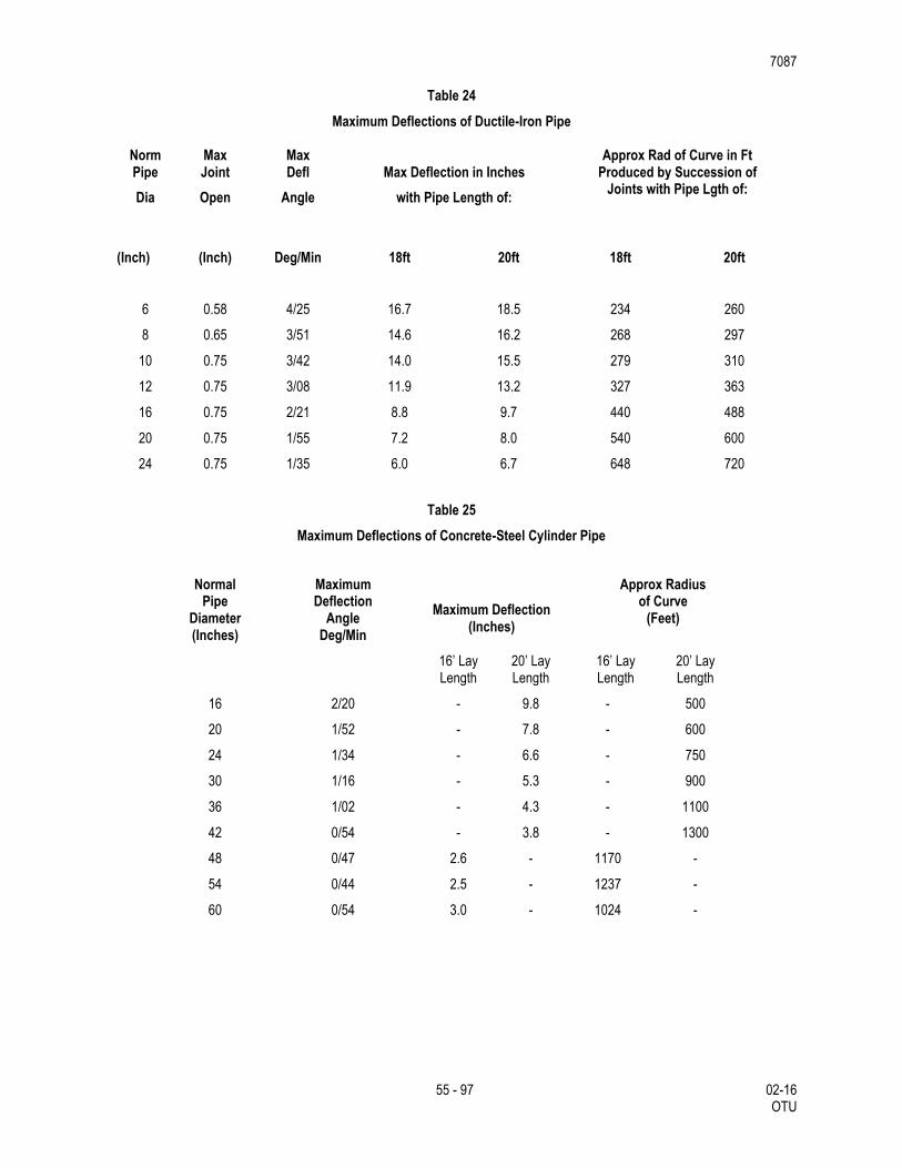
7087
55 - 97 02-16 OTU
Table 24
Maximum Deflections of Ductile-Iron Pipe
Norm Max Max Approx Rad of Curve in Ft Pipe Joint Defl Max Deflection in Inches Produced by Succession of
Dia Open Angle with Pipe Length of: Joints with Pipe Lgth of:
(Inch) (Inch) Deg/Min 18ft 20ft 18ft
20ft
6 0.58 4/25 16.7 18.5 234 260
8 0.65 3/51 14.6 16.2 268 297
10 0.75 3/42 14.0 15.5 279 310
12 0.75 3/08 11.9 13.2 327 363
16 0.75 2/21 8.8 9.7 440 488
20 0.75 1/55 7.2 8.0 540 600
24 0.75 1/35 6.0 6.7 648 720
Table 25
Maximum Deflections of Concrete-Steel Cylinder Pipe
Normal
Pipe Diameter (Inches)
Maximum Deflection
Angle Deg/Min
Maximum Deflection
(Inches)
Approx Radius of Curve
(Feet)
16’ Lay Length
20’ Lay Length
16’ Lay Length
20’ Lay Length
16 2/20 - 9.8 - 500
20 1/52 - 7.8 - 600
24 1/34 - 6.6 - 750
30 1/16 - 5.3 - 900
36 1/02 - 4.3 - 1100
42 0/54 - 3.8 - 1300
48 0/47 2.6 - 1170 -
54 0/44 2.5 - 1237 -
60 0/54 3.0 - 1024 -
7087
56 - 97 02-16 OTU
3.2.13. Cutting Pipe.
The cutting of pipe for inserting valves, fittings or closure pieces is to be accomplished so as to produce a smooth end at right angles to the axis of the pipe. Strictly follow the recommendations of the pipe manufacturer. Under no circumstances is a workman not equipped with proper safety goggles and helmet and other required safety attire permitted to engage in this work.
Asbestos-Cement (AC): No field cutting will be allowed on asbestos-cement pipe. Repairs to AC pipe shall be accomplished by removing one full joint of AC pipe and replacing with appropriate PVC or Ductile Iron pipe and fittings. Information about handling AC pipe may be obtained through the SAWS homepage at http://www.saws.org.
All cuts made on ductile-iron pipe are to be done with a torch or power saw. The cuts are to be made at right angles to the pipe axis and are to be smooth. The edges of the cut are to be finished smoothly with a hand or machine tool to remove all rough edges. The outside edge of pipe should be finished with a small taper at an angle of about 30°.
Field Cut PVC (C-900 and C-905 and C-909) using a power saw with a steel blade or abrasive disc depending on the size of pipe. If a bevel is needed after field cutting, it should be in accordance with Uni-Bell recommendations.
To facilitate future repair work on water mains, no sections less than 3 feet in length between fittings is allowed.
3.2.14. Coating and Wrapping Underground Pipe.
3.2.14.1. Steel Pipe.
Steel pipe, bends and special are to be prepared, primed, painted or wrapped in the field as follows.
Exterior Surface Above Ground: Exterior surfaces of new pipe and appurtenances installed are to be thoroughly cleaned to bare metal by high speed wire brushing, scraping or other suitable methods approved by Engineer, given a single coat of industrial grade rust inhibitive primer and two finish coats of aluminum paint.
Exterior Surfaces Underground: Exterior surface of steel pipe, bends and specials installed in open trench are to be thoroughly cleaned to bare metal by high speed wire brushing, scraping or other suitable methods approved by Engineer, given a single coat rust inhibitive primer and wrapped with polyvinyl tape in accordance with AWWA C-203-91 “Protective Coatings for Steel Water Pipelines,” (Appendix C).
The procedure for coating flanged joints and mechanical coupling joints when used with steel pipe is to be as specified.”
Field Welded Joints: After installation of pipe, bends, and specials, all ends of pipe adjacent to welded field joints, including the weld proper, shall be cleaned, primed, painted or wrapped as specified for the pipe adjacent to the weld.
Interior Surfaces: The interior surfaces of all steel pipe, fittings and specials shall be cleaned by sandblasting and then primed and coated with a cement mortar lining. Cement mortar-lined and coated steel pipe shall be used for transmission mains 16 inch and larger.
All cement-lined steel pipe shall be prepared with the following processes:
3.2.14.1.1. Steel pipe shall not be tested until the factory-applied mortar lining and coatings on all piping and specials have been in place for a minimum of 14 days. Steel piping with cement mortar field applied to the interior of
7087
57 - 97 02-16 OTU
the pipe shall not be filled with water until a minimum of 8 hours has elapsed after the final placement of cement mortar, unless otherwise approved by the Engineer.
3.2.14.1.2. (Contractor to submit details of all specials, and of the lining and coating.
3.2.14.1.3. Use lining conforming to the latest provision of AWWA C205 or most applicable approved equal provision, except as be noted otherwise in the contract documents.
3.2.14.1.4. Cement used in mortar lining shall be Portland Cement, per the latest provision of ASTM C150 or most applicable approved equal provision, Type II or V for lining.
3.2.14.1.5. Pipe shall be cement mortar lined in the shop by the centrifugal process, in accordance with the latest provision of AWWA C205 or most applicable approved equal provision.
Cement mortar-lined pipe shall be braced as required to maintain roundness during the shipping and handling activities and shall have ends capped prior to shipment. For pipe 14 inch nominal diameter and larger, the finished ID after lining shall be the nominal size. For pipe 12 inch nominal diameter and smaller, standard OD pipe sizes shall be furnished.
3.2.14.2. Ductile-Iron Pipe.
3.2.14.2.1. Open Trench
Ductile-iron pipe to be installed in a trench is to be protected in the following manner. Each pipe joint is to be covered with a 4 mil thick polyethylene sleeve that is 2-ft. longer than the pipe joint. The sleeve is to cover the full length of the pipe joint, lap over 1-ft. on each end of the adjoining pipe joints and be secured with a minimum of 2 circumferential turns of pressure sensitive polyvinyl tape. Excess material should be neatly drawn up around the pipe barrel, folded into an overlap on top of the pipe and held in place by means of pieces of pressure sensitive tape at approximately 5-ft. intervals. After assembling the joint, the polywrap tube from the previously installed pipe is to be pulled over the joint and secured by the contractor. The polywrap tube from the new joint is to be pulled over the first tube and secured to provide a double seal.
Cast iron and ductile-iron fittings are to be completely wrapped in 8 mil thick polyethylene films with a minimum of 1-ft. overlap on each end and appropriately taped. Laps are to cover joints with adjoining pipe joints or fittings when installed. Fire hydrant barrel from the surface to the valve is to be wrapped as specified herein.
Any damaged areas in the polyethylene film are to be repaired by covering the area with a sheet of polyethylene film large enough to lap over the damaged area 1-ft. minimum in any direction and appropriately taped. Take care at service to locations to insure that tape extends beyond corporation and onto service line pipe 1 foot.
Prior to placing pipe in the trench, a cushion of approved materials is to be placed in the trench as required by Section 3.3., Backfill material is to be carefully placed on the pipe so as to avoid any damage to the polyethylene sleeve.
The Contractor shall use care to protect and preserve the polyethylene wrap around ductile iron water mains when installing service corporations. The required method is to wrap pipe tape around the pipe over the polywrap in the area to be tapped. The tap is to be made through the tape and polywrap. It is not necessary to remove and replace poly wrap. All exposed pipe, the corporation, and the first 3 feet of the service shall be wrapped and taped to achieve a complete seal. In addition, a sand envelope shall extend over and around the connection to a depth of eight inches above the main.
3.2.14.2.2. In Casing
7087
58 - 97 02-16 OTU
Where ductile-iron pipe is installed in a bore, the pipe is to be to thoroughly clean down to the coal-tar enamel pipe coating by approved methods. Where damaged, a prime coat compatible to the polyvinyl tape to be used is to then be applied to the pipe. Following application of prime coat, wrap pipe with Scotchrap, trantex V-10 polyvinyl tape, or approved equal. Tape shall not be applied until prime coat is completely dry.
The tape shall be spirally and tightly wrapped on each section of the pipe with a 50% lap. The wrap shall be made to the bell on the bell end and to a point 6 inches from the spigot end. The joint shall be protected with tape 6 inches in width on pipe 12 inches or less in size and with tape 8 inches in width on pipe greater than 12inches in size.
3.2.15. Protective Coating and Wrapping on Joints.
All bolts and nuts installed for underground service on valves, fire hydrants, cast-iron mechanical joint fittings, pipe joints, and other ferrous metal appurtenances are to be packed in an approved protective coating material after installation. After the joint has been made and bolts drawn to proper tension, the joint including glands, flanges, bolt heads, and nuts are to be covered with an approved coating. Such protective coating is supplemental to anti-corrosive sand embedment. Asphaltic coatings such as Talcote is not allowed. Coating and wrapping of joints is to be considered subsidiary to the installation and will not be paid for directly.
Steel Pipe Field Welded Joints: After installation of pipe, bends and specials, all end of pipe adjacent to welded field joints, including the weld proper, shall be cleaned, primed, painted or wrapped as specified for the pipe adjacent to the weld.
3.2.16. Joint Assembly.
Rubber Ring Joints: The installation of pipe and the assembly of rubber ring joints for ductile-iron pipe, concrete-steel cylinder pipe and asbestos cement pipe, is to conform to the pipe manufacturer's assembly instructions. The method of inserting spigot ends of pipe in bells or collars known as “stabbing” is not permitted with pipe larger than 6-in.in size. Spigot ends of pipe larger than 6-in. in size must be properly inserted in the joint by means of suitable pushing or pulling devices.
Mechanical Couplings: The installation of mechanical couplings is to be assembled and installed according to the standards recommended by the manufacturer. Prior to the installation of the mechanical coupling, the pipe ends are to be cleaned by wire brush or other acceptable method to provide a smooth bearing surface for the rubber compression gasket. The pipe is to be marked to align the end of the coupling which will center it over the joint. After positioning, the nuts are to be drawn up finger tight. Uniform pressure on the gaskets is to be applied by tightening alternate bolts on the opposite side of the circle in incremental amounts. Final tensioning is to be accomplished with a torque wrench and in a manner similar to the tightening procedure. The coupling is to then be left undisturbed for 24 hours to allow the gaskets to “pack-in”. Final torque check is to then be made prior to coating and wrapping the joint. Table 21, Torque for Mechanical Couplings, sets forth the proper torque for various sized mechanical couplings and is included for the convenience of the Contractor.
Restrained Joints: Install restraint joints as shown on plans or as directed by Engineer. Install in accordance with manufacturer’s recommendations.
7087
59 - 97 02-16 OTU
Table 26
Torque for Mechanical Couplings
Coupling Size Bolt Diameter Torque
2” to 24” 5/8” 75 ft/lb
2” to 24” 3/4” 90 ft/lb
30” and 36” (1/4”x7” Middle Rings) 5/8” 65 ft/lb
30” thru 36” (3/8” & heavier Middle Rings)
5/8” 70 ft/lb
30” to 48” 3/4” 80 ft/lb
48” to 72” 3/4” 70 ft/lb
3.2.17. Gray Iron and Ductile Iron Fittings
Fittings: Fittings 6-in. through 12-in. in size are to be either mechanical joint, push-on joint short body, or push-on joint compact body unless otherwise stated on the plans. Fittings shall be installed with the thrust blocking or joint restraint shown in standard drawing DD-839 series. Fittings 16-in. through 24-in. in size are to be mechanical joint type unless otherwise specified on the plans. Adaptors are to be used where necessary to provide a transition between asbestos-cement pipe and the fittings. Restraint or thrust blocking is to be provided as specified on the plans or as directed. Anti-corrosion embedment incidental to all installed cast-iron fittings shall be provided as specified in and no separate payment will be made for this embedment.
Cleaning Ductile Iron: All lumps, blisters, and excess coal-tar coating is to be removed from the ends of ductile-iron pipe fittings. The outside of the spigot and the inside of the bell is to be wire-brushed and wiped clean, dry, and free from oil and grease before the pipe is laid. The interior of the pipe is to be blown clean with compressed air or swabbed out clean and dry as directed. Immediately prior to placing any pipe in the trench the interior is to be cleaned by an approved brush or swab or with compressed air to remove all dirt and foreign materials. All pipe and fittings are to be inspected by the Contractor for defects while suspended above ground.
3.2.18. Corrosion Protection for Ferrous Pipe, Fittings, and Valves
Except as otherwise shown on plans or as direct, anticorrosion embedment is to be provided for all ductile-iron pipe, fittings, and valves and at all valve fittings or outlets for nonferrous or reinforced concrete steel cylinder pipe. The embedding material is to be Modified Grade 5 gravel washed sand which conforms to the requirements set forth in Section 2.17.
Prepare the trench in accordance with applicable provisions of Section 3.1. After subgrade has been prepared, lay pipe to grade in accordance with plans and specification. Pipe, fitting or valve are to be firmly embedded in and surrounded by an insulating blanket of embedding material. The minimum thickness of this blanket is to be 6 inches in every direction
3.2.19. Tie-in to Existing Mains
The Contractor shall make tie-ins from new water mains to existing water mains as shown in the contract documents or as directed by the Engineer. The Contractor shall be responsible for all shutdowns and isolation of the existing mains; cutting pipe for the connection; dewatering the excavation; customer notification of the shutdown; and all other requirements as directed by the Inspector in order to provide completion of this effort in a safe and secure manner. Work performed by the Contractor on mains 16 inches and larger, will require operation of any valves by SAWS forces. Therefore ample coordination beforehand (2 work days) shall be provided by the Contractor for this interaction to occur. All tie-ins shall be done after
7087
60 - 97 02-16 OTU
normal work hours, (8am-5pm). During construction, the planned shutdown and tie-in work shall be coordinated through and approved by the Inspector with a minimum of two weeks prior notice of such activity and accomplished at a time which will be at the least inconvenience to the customers. No additional compensation will be provided for tie-ins accomplished after normal working hours.
Tie-in to existing mains of asbestos cement (AC) pipe, the Contractor shall observe and comply with all federal, state and local laws, ordinances and regulations regarding the management of asbestos containing materials. At the minimum, work involving AC pipe should be overseen by a person who has received asbestos training and is familiar with the National Emissions Standards for Hazardous Air Pollutants (NESHAP). If greater than 260 linear feet of pipe is to be removed, written notification to the Texas Department of Health (TDH) 10 days prior commencing with the removal of AC pipe is required. At each location shown in the plans and/or identified by the Contractor to involve AC pipe, the Contractor will be required to coordinate with TxDOT’s Evergreen Contractor for the removal of the necessary amount of AC pipe required to make the connection without creating any friable material. TxDOT’s Evergreen Contractor will remove whole sections of AC pipe so that the Contractor can make the tie-in at the nearest joint. TxDOT’s Evergreen Contractor will remove the AC pipe, store it in a secure Engineer approved location, and then dispose of it. Prior to requiring the services of TxDOT’s Evergreen Contractor, the Contractor shall notify the Engineer and the Owner of the Utility of the work schedule a minimum of two weeks in advance of requiring such services in order not to delay the overall project. Delays or claims made by the Contractor, resulting from the failure to provide advanced notification and schedule coordination with TxDOT’s Evergreen Contractor, will not be a basis for additional compensation.
3.2.20. Abandonment of Old Mains and Valves
Regarding planned main abandonment, the Contractor shall accomplish all cutting, capping, plugging, and blocking necessary to isolate those existing mains retained in service from those abandoned. The open ends of abandoned mains and all other openings or holes in such mains occasioned by cutting or removal of outlets shall be blocked off by manually forcing cement grout or concrete into and around the openings in sufficient quantity to provide a permanent substantially watertight seal. Abandonment of old, existing water mains will be considered subsidiary to the work required, and no direct payment will be made.
When specified or shown otherwise in the contract documents, Contractor shall remove the main and all related appurtenances that are to replaced, or will no longer be in service, and all effort to accomplish this requirement will be considered subsidiary to the work required, and no direct payment will be made.
Abandoned Valves: Valves abandoned in the execution of the work shall have the valve box and extension packed with sand to within 8 inches of the street surface. The remaining 8 inches shall be filled with 2,500 psi concrete or an equivalent sand-cement mix and finished flush with the adjacent pavement or ground surface. The valve covers shall be salvaged and returned to the Owner.
New/Existing Valves: At no time during the project work shall any valves be covered or rendered inaccessible for operation due to any activities by the Contractor. Any work during construction activities will be suspended until this requirement is met. No claims for cost or schedule delays will be accepted.
3.2.21. Jacking, Boring, or Tunneling Pipe
Jacking: Suitable pits or trenches shall be excavated for the purpose of jacking operations for placing end joints of the pipe. When trenches are cut in the side of embankment, such work shall be securely sheeted and braced. Jacking operations shall in no way interfere with the operation of railroads, streets, highways or other facilities and shall not weaken or damage such facilities. Barricades and lights shall be furnished as directed by the Engineer to safeguard traffic and pedestrians.
The pipe to be jacked shall be set on guides to support the section of pipe being jacked and to direct it in the proper line and grade. Embankment material shall be excavated just ahead of the pipe and material removed through the pipe, and the pipe forced through the opening thus provided.
7087
61 - 97 02-16 OTU
The excavation for the underside of the pipe, for at least ⅓ of the circumference of the pipe, shall conform to the contour and grade of the pipe. A clearance of not more than 2 inches may be provided for the upper half of the pipe.
The distance that the excavation shall extend beyond the end of the pipe shall depend on the character of the material, but it shall not exceed 2 feet in any case.
The pipe shall be jacked from downstream end. Permissible lateral or vertical variation in the final position of the pipe from line and grade will be as shown on the plans or as determined by the Engineer.
Any pipe that cannot be repaired to its original condition or is damaged in jacking operations shall be removed and replaced at the Contractor's expense. Jacking pits shall be backfilled immediately upon completion of jacking operations.
Excavation for "Boring" pits and installation of shoring shall be as outlined under "Jacking." Boring operations may include a pilot hole which shall be bored the entire length of crossing and shall be used as a guide for the larger hole to be bored. Water or drilling fluid may be used to lubricate cuttings. Variation in line and grade shall apply as specified under "Jacking."
Tunneling: Tunneling may be used when the size of the proposed pipe would make the use of tunneling more satisfactory than "Jacking" or "Boring." The excavation for pits and the installation of shoring shall be as specified under "Jacking." The lining of the tunnel shall be of the material shown on the plans.
Access holes for grouting annular space shall be spaced a maximum of 10 feet.
Joints: Joints for pipe for "Jacking," "Boring," or "Tunneling,” shall be as specified in these specifications, or as shown on the project plans or shop drawings as per pipe manufacturer's recommendation.
Grouting of Bores or Tunnels: Annular Space between casing pipe and limits of excavation (borehole) shall be pressure grouted, unless otherwise specified on the plans.
3.2.22. Cutting-in Valves.
The work involved in cutting a valve into an existing main is to consist of excavation and backfilling with approved selected material; hauling and disposition of surplus excavation and other materials; installation of the valve, valve box assembly, all pipe cut used to complete cut-in; reaction blocking; polyethylene wrapping where required.
3.2.23. Tapping Sleeves and Valves
Size on size taps are not permitted.
The work involved in the installation of a tapping sleeve and valve is to consist of excavation, backfilling the excavation with approved selected material, installing the tapping sleeve, reaction blocking, tapping valve, valve box assembly, concrete collar where subjected to street traffic, and a cast iron lid. New taps will not be permitted closer than 2 feet of a joint or existing tap. The use of a shell type cutter shall be required with tapping sleeves and valves. Whenever working on potable or recycled water system, disinfect the shell cutter with bleach prior to start of work. The cutting edge is to be sharp and round. Inspector will reject defective cutters.
Air test tapping sleeves to 50 psi prior to tapping main line.
The valve box shall be placed in such a manner to prevent shock or stress from being transmitted to the valve. Valve boxes shall be centered over the valve’s operating nut with the box cover flush with the finished pavement surface or located at another level as directed by the Inspector. Valve boxes located in streets or other areas subject to vehicular traffic shall be provided with concrete collars as shown in the accompanying
7087
62 - 97 02-16 OTU
standard drawings. Collars around such valve boxes shall be formed and finished off neatly and in a sound workmanlike manner.
3.2.24. Cutting-in Tees
The work involved in cutting in a tee is to consist of excavation, shut-down and isolation of existing main to which the new main is to be connected, cutting pipe for connection, dewatering the excavation, customer notification of service interruption where required, installation of all pipe used to complete the connection, all necessary tie-ins (connection to existing or new main), fittings, approved reaction blocking required and backfilling the excavation with approved selected materials or flowable backfill if required. Where the installation of a valve is required, payment will be for valve accordance with this specification.
The processes associated with disturbing and restoring pavements (any type), curbs, sidewalks, backfilling to final grade, flowable backfill (if required) and sodding for the installation of a cut-in tee will be considered subsidiary to the work and must comply with the applicable TxDOT Specification, any other governing entity’s specifications, and applicable street cut policies, ordinances, or permits.
3.2.25. Pipe Joint Restraint System
Pipe joint restraints shall be utilized to prevent movement for PVC push-on bell and spigot pipe connections. The restrainer may be adapted to connect a plain end PVC pipe to a ductile iron mechanical joint (MJ) bell fitting. Joint restraint is to be non-directional and installed to fully restrain system. All pipe and fitting systems with restrained joints shall be identified by applying an adhesive-backed warning tape to the top of the pipe and for the full length of the pipe, regardless of the type of pipe. For plastic pipes the warning tape shall be applied directly to the top of the pipe. For metal pipes and fittings the warning tape shall be applied to the top of the polyethylene film wrap.
3.2.26. Concrete Encasement, Cradles, Saddles and Collars
Concrete Encasement. When concrete encasement is shown on the plans or when directed, the trench is to be excavated and fine graded to a depth conforming to the details and sections shown on the plans. The pipe is to be supported by pre-cast concrete blocks of the same strength as the concrete for encasement and securely tied down to prevent floatation. Encasement concrete is to be placed to a depth and width conforming to details and sections shown on the plans.
Concrete Cradles. When concrete cradles are shown on the plans or when directed, the trench is to be prepared and the pipe supported in the same manner as described in Concrete Cradles, of this Section. The cradle shall be constructed in accordance with details and sections shown on the plans. Strap/Tie Downs shall be No. 4 rebar diameter minimum or better as determined by the Water System Inspector.
Concrete Saddles. When shown on the plans or when directed, pipe to receive concrete saddle is to be backfilled in accordance with Section 3.D. of this specification to the spring line and concrete placed for a depth and width conforming to details and sections shown on the plans.
Concrete Collars. When shown on the plans or when directed, concrete collars are to be constructed in accordance with details and sections shown on the plans.
3.2.27. Fire Hydrants and Miscellaneous Appurtenances
3.2.27.1. Fire Hydrants.
Hydrants are to be connected to the main as shown on the plans or as directed by the Engineer. They are to be installed in a manner which will provide complete accessibility and in a sage location where there is a minimum possibility of damage from vehicles or injury to pedestrians.
7087
63 - 97 02-16 OTU
When the hydrant is placed directly behind the curb the hydrant barrel is to be set so that no portion of the hydrant will be less than 12 inches nor more than 7-ft. from the back of the curb.
When the hydrant is set in the lawn space between the curb and the sidewalk or between the sidewalk and the property line no portion of the hydrant or nozzle cap is to be within 6-in. of the sidewalk. Setting final grade of fire hydrants to match proposed or existing field conditions is the responsibility of the contractor.
Hydrants are to be set in accordance with plans and details are to be set plumb and are to have their nozzles parallel with or at right angles to the curb with the pumper nozzle facing the curb. Drainage and concrete pad are to be provided at the base of the hydrant as shown on the plans. No fire hydrant drainage system or pit is to be connected to a storm sewer or to a sanitary sewer.
Restrained Joints: Restrained mechanical joints that require field welding or groove cuts into the pipe barrel for restrain will not be accepted. Restrained joints shall be furnished for pipe at all changes in direction at indicated on plans, details, or as directed. Restrained mechanical joints shall be locked mechanical joints. Joints shall be capable of test pressure twice the maximum sustained working pressure of 350 psi for ductile iron pipe and PVC.
Replacing and Relocating Existing Fire Hydrants: When existing fire hydrants are to be replaced or relocated, the work is to be accomplished by either of the following:
Cutting or installing a tee of the size and type indicated on plans or as directed.
Using a tapping sleeve and valve of the size and type indicated on plans to install a new fire hydrant to
an existing or new water main. Size on size taps is not permitted.
Relocating the existing fire hydrant by closing the existing fire hydrant, extending the fire hydrant branch
and installing the existing fire hydrant as specified herein.
Salvage the existing fire hydrant and other materials as designated in the field by the Construction Inspector and deliver to Water System material storage yard located at 3930 East Houston Street. Fire hydrant branches are to be abandoned by cutting and capping fire hydrant cast iron tee at the service main and surface restored to its original condition.
After the fire hydrant has been set, paint hydrant with suitable primer and finish with oil-based aluminum paint from top of hydrant to a point 18-20 inches below center line of the pumper nozzle and apply to all exposed metal surfaces above the hydrant base flange. The payment for fire hydrant painting is to be included in the unit cost for installing the fire hydrant.
Ductile iron pipe, cast iron and ductile iron fittings, and valves used in the placement of fire hydrants and connections to the main will be considered part of the fire hydrant installation and not a part of the main construction. No separate payment will be made for this pipe. Hydrants shall be connected to the mains as shown in the contract documents or as directed by the Engineer. Hydrants shall also be installed in a location where there is accessibility and in a safe location where there is a minimum possibility of damage from vehicles or injury to pedestrians.
3.2.27.2. Gate Valves, Valve Boxes, Adjustments
Gate valve installation shall include valve, reaction blocking, cast iron boot, valve box extension (having ductile iron riser pipe), valve box, concrete collar (where subjected to vehicular traffic), and valve box lid. Gate valves constructed in the terrace shall be constructed with No. 3 bars all around.
The valve box shall be placed in such a manner to prevent shock or stress being transmitted to the valve. All valves located 6 feet and deeper shall include valve key extensions inside the valve box. The Contractor has the option to install fully adjustable valve box and valve key extension systems, on all valves located between 6 feet and 13 feet. Adjustable valve box and valve key extension systems shall be centered over the valve’s operating nut with the box cover flush with the finished pavement surface or located at another level as directed by the Engineer. Valve boxes located in streets or other area subject to vehicular traffic shall be provided with concrete collars as shown in these standard drawings.
7087
64 - 97 02-16 OTU
Collars around such valve boxes shall be formed and finished off neatly and in a sound workmanlike manner. Valve pits shall be located so that the valve operating nut is readily accessible for operation through the opening in the valve box. The valve box shall be set flush with the finished pavement surface or at other finish elevations as may be specified. Pits shall be constructed in such a manner to permit minor valve repairs and provide protection to the valve and pipe from impact (where penetrating through pit walls).
In Pressure Zones 9-16, all valves 6 inches and larger shall be supported on a concrete pad in accordance with details shown in the plans.
Existing valve boxes located within the limits of new street construction which are in conflict are to be adjusted to match proposed finish grades.
Valve boxes installed as part of a new valve and mainline construction project are considered “new valves.” Adjustments to “new valves” are incidental to the installation of the valve. No separate pay will be given to adjust “new valves” to finished grade.
3.2.27.3. Air Release Assembly
Air release valves and appurtenant items are to be installed at the locations shown on the plans unless otherwise directed.
Install air release assemblies in open trench in accordance with plans and details. Assemblies include the valve, valve box, tapping saddle, pipe fittings, accessories and appurtenances. It also includes service line and tap to main. Air release assemblies installed in parkways or easements and outside of street pavement shall be installed in accordance with plans.
Air release assemblies installed on steel pipe attached to bridge structure includes the outlet on the steel pipe, valve, valve box, pipe fittings, security enclosure, accessories and appurtenances.
3.2.27.4. Blow-offs
Permanent and temporary blow-off assemblies shall be installed where shown on the plans and/or at locations designated by the Engineer/Owner and at the end of all dead end mains in accordance with the Texas Administrative Code (TAC) rules to include 30 TAC § 290.44.(d)(5), (6).
The permanent blow-off shall consist of the following: all galvanized iron pipe, valve, and fittings of the various sizes shown on the plans, 6 inch valve box assembly and concrete collar around the valve box. The temporary blow-off shall consist of the following; all galvanized iron pipe, valve and fittings of the various sizes shown on the plans. Valve box shall be raised or installed to finished grade and installed in accordance with the details.
3.2.27.5. Anchorage and Blocking
Suitable reaction blocking or anchorage is to be provided at all dead ends, plugs, caps, tees, crosses, valves and bends as shown on the plans. All mechanical restraints are to be bidirectional. Anchor blocks are to be constructed solidly behind the fitting and symmetrical with the axis of resultant thrust except where this is not possible as in the case of gravity anchorage for vertical bends. Special ties and anchor fittings may be utilized in conjunction with blocking when shown on the plans or as directed.
Thrust blocking is to be a minimum of Class “A” (3,000 psi), concrete placed between solid ground and the fitting except as otherwise shown on the plans. The area of bearing in contact with solid ground is to be that shown on the plans or as directed.
All thrust blocking placed in conjunction with mains and appurtenances constructed in Pressure Zones 9 through 15 shall be in accordance with SAWS Standard Drawings DD-839 Series as shown on the plans. In all cases, the design of thrust blocking shall be of sufficient size to withstand a soil pressure of 3000 psf,
7087
65 - 97 02-16 OTU
unless specified otherwise in the job plans or specifications. The maximum soil pressure value that will be allowed for the design of thrust blocking shall be 5000 psf. When soil pressure bearing values of 4000 psf or 5000 psf are recorded for design of thrust blocks, copies of soil tests made for determining the bearing value of the soil is question shall be submitted to the Engineer for verification.
The blocking is to be placed so that pipe and fitting joints will be accessible. Pipe polywrap is to be placed between the pipe or fitting and the concrete.
The reaction block on the unused branch of a tee is to be poured separately from the block across the back of the tee. If they are poured simultaneously, a rigid partition is to be placed between the blocks.
Valves 12-in. and larger in size are to be supported on a concrete pad extending vertically from 12-in. below the bottom of the valve to the lower quarter point of the hub and laterally from face to face of hubs and transversely from wall to wall of the trench.
3.2.27.6. Butterfly Valves
Butterfly valve installation shall include: butterfly valve, coated and wrapped steel pipe nipple with reaction stop ring, concrete reaction blocking, cast-iron boot, valve box extension (ductile iron riser pipe), valve box and lid, concrete collar where subjected to vehicular traffic, all couplings and all coupling adapters required to complete the connection. The entire valve except for the operating nut shall be coated with an approved SAWS sewer structural coating, and wrapped with Polywrap. Butterfly Valves constructed in terrace shall be constructed with No. 3 bars all around.
The valve box shall be placed in such a manner to prevent shock or stress being transmitted to the valve. All valves located 6 feet and deeper shall include valve key extensions inside the valve box. The Contractor has the option to install fully adjustable valve box and valve key extension systems on all valves located between 6 feet and 13 feet. Adjustable valve box and valve key extension systems shall be centered over the valve’s operating nut with the box cover flush with the finished pavement surface or located at another level as directed by the Engineer. Valve boxes located in streets or other areas subject to vehicular traffic shall be provided with concrete collars as shown on the plans. Collars around such valve boxes shall be formed and finished off neatly and in a workmanlike manner.
3.3. Backfill
3.3.1. Initial Backfill.
Initial backfill is defined as backfill having a thickness in its compacted state from the surface of the bedding to a point 1 foot above the top of pipe. The first lift of initial backfill is to be inspected and approved prior to placement of the second lift. The second lift of initial backfill material is to extend from the spring line of the pipe with a minimum of one foot above the top of the pipe. The second lift is to be evenly spread in a similar manner as the first lift.
For diameters 24 inches and larger, simultaneously spread initial backfill material alongside, under the lower quadrant of pipe and over the pipe in 12 inch lifts to a point sufficient to a minimum of 1 foot above the top of pipe.
Consolidate initial backfill material to assure it is incorporated. A handheld vibrator, commonly used for concrete work, can be used for this purpose. The vibrator shall be inserted every 3 feet on each side of pipe.
3.3.2. Secondary Backfill.
Secondary backfill is defined as backfill from 1 foot above the top of pipe to the top of the trench or bottom of pavement section. Secondary back fill is to be constructed in accordance with details shown on plans and these specifications.
7087
66 - 97 02-16 OTU
Secondary backfill material shall be placed in maximum 12 inch loose lifts or as directed.
3.3.3. Sand Backfilling of Cross Trenches and Open Holes.
Blow-offs, tie-ins, air release valves, and service lines, meter boxes, or other specials are to be backfilled with sand and thoroughly consolidated by saturating with water, unless otherwise directed. The use of mechanical tamping equipment for compaction of backfill will not be permitted at such locations. Disposal of surplus excavated material and placement of sand is to be considered subsidiary to trenching and backfilling and will not be paid for directly.
3.3.4. Trench Backfill Across Traffic Arteries.
Any trench in or across traffic arteries is to be backfilled immediately after the pipe is installed unless the Engineer determines unusual conditions exist that render immediate backfilling unfeasible.
3.3.5. Flowable Backfill.
Instead of normal backfill materials, the Contractor is to backfill the trench with flowable backfill with fly ash material at the locations shown on the plans and/or at locations directed. The flowable backfill material and operation is to be in accordance with Item 401, “Flowable Backfill”.
3.4. Flushing and Testing Mains
3.4.1. Flushing
Immediately upon completion of water main work, the Contractor shall flush all mains affected by the scope of the work. This flushing shall consist of completely filling sections of main between valves and then displacing such initial volumes of water by introducing clear water from existing facilities into and through the main to the point of discharge from the main being flushed. The flow-through shall continue until it is determined all dust, debris, or foreign matter that may have entered during pipe laying operations has been flushed out. All new mains shall then be left under system pressure for testing.
To avoid damage to pavement and inconvenience to the public, fire hoses shall be used to direct flushing water from the main into suitable drainage channels or sewers. The contractor is to coordinate with the Inspector prior to flushing.
3.4.2. Operation of Valves
No valve in the distribution system is to be operated by the Contractor without prior permission of the Inspector. The Contractor shall notify the Inspector when a valve is to be operated and shall only operate the valve in the presence of the Inspector.
3.4.3. Hydrostatic Tests
After the pipe has been installed and backfilled and all service laterals, fire hydrants and other appurtenances installed and connected, a hydrostatic pressure followed by a leakage test will be performed. Except in the high pressure sections of the water distribution system (Pressure Zones 9-16) where test pressures will exceed 150 psi, all new mains shall be hydrostatically field tested at a maximum test pressure of 150 psi before acceptance by the Engineer or Inspector. Where designated as "High Pressure Area," all new mains shall be hydrostatically field tested at a maximum test pressure of 200 psi before acceptance by the Engineer or Inspector. It is the intent of these Specifications that all joints be watertight and that all joints which are found to leak by observation during any test shall be made watertight by the Contractor. When repairs are required, the hydrostatic field test shall be repeated until the pipe installation conforms to the specified requirements and is acceptable to the Engineer/Inspector. The Contractor shall insure that the Engineer/Inspector be present for the duration of the pressure test.
7087
67 - 97 02-16 OTU
3.4.4. Test Procedures
After the new main has been laid and backfilled as specified, but prior to chlorination and replacement of pavement, it is to be filled with water for a minimum of 24 hours and then subjected to a hydrostatic pressure test.
The specified test pressure is to be supplied by means of a pump connected to the main in a satisfactory manner. The pump, pipe connection, and all necessary apparatus including gauges and meters are to be furnished by the Contractor. Unless otherwise specified, the Water System Company will furnish water for filling lines and making tests through existing mains. Before applying the specified test pressure, all air is to be expelled from the main. To accomplish this, taps are to be made, if necessary, at the points of highest elevation and afterwards tightly plugged at no cost to the Department. At intervals during the test, the entire route of the new main is to be inspected to locate any leaks or breaks. If any are found, they are to be stopped or repaired. The test is to be repeated until satisfactory results are obtained. The hydrostatic test is to be made so that the maximum pressure at the lowest point does not exceed the specified test pressure.
The duration of each pressure test is to be a minimum of 4 hours for new mains in excess of 1,000-ft. and a minimum of 1 hour for new mains less than 1,000-ft after the main has been brought up to test pressure. The test pressure is to be measured by means of a tested and properly calibrated pressure gauge acceptable to Engineer. All pressure tests are to be continued until the Engineer is satisfied that the new main meets the requirements of these specifications.
Should any test of pipe in place disclose leakage greater than listed in Table 27 or 28, Hydrostatic Test Leakage Allowances, the Contractor is to, at his expense, locate and repair the defective joints until the leakage is within the specified allowance. Leakage is defined as the quantity of water supplied into the newly laid main, or any valve section of it, necessary to maintain the specified leakage test pressure after the main has been filled with water and the air expelled. The Contractor is to notify the Engineer prior to beginning the test, and the Water System Company's Inspector is to be present during the pressure test.
PVC pipe leakage allowances shall conform to DI leakage allowances listed on Tables 27 and 28, Hydrostatic Test Leakage Allowances.
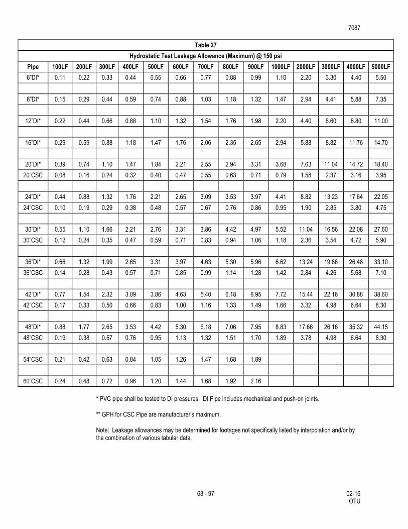
7087
68 - 97 02-16 OTU
Table 27
Hydrostatic Test Leakage Allowance (Maximum) @ 150 psi
Pipe 100LF 200LF 300LF 400LF 500LF 600LF 700LF 800LF 900LF 1000LF 2000LF 3000LF 4000LF 5000LF
6”DI* 0.11 0.22 0.33 0.44 0.55 0.66 0.77 0.88 0.99 1.10 2.20 3.30 4.40 5.50
8”DI* 0.15 0.29 0.44 0.59 0.74 0.88 1.03 1.18 1.32 1.47 2.94 4.41 5.88 7.35
12”DI* 0.22 0.44 0.66 0.88 1.10 1.32 1.54 1.76 1.98 2.20 4.40 6.60 8.80 11.00
16”DI* 0.29 0.59 0.88 1.18 1.47 1.76 2.06 2.35 2.65 2.94 5.88 8.82 11.76 14.70
20”DI* 0.39 0.74 1.10 1.47 1.84 2.21 2.55 2.94 3.31 3.68 7.63 11.04 14.72 18.40
20”CSC 0.08 0.16 0.24 0.32 0.40 0.47 0.55 0.63 0.71 0.79 1.58 2.37 3.16 3.95
24”DI* 0.44 0.88 1.32 1.76 2.21 2.65 3.09 3.53 3.97 4.41 8.82 13.23 17.64 22.05
24”CSC 0.10 0.19 0.29 0.38 0.48 0.57 0.67 0.76 0.86 0.95 1.90 2.85 3.80 4.75
30”DI* 0.55 1.10 1.66 2.21 2.76 3.31 3.86 4.42 4.97 5.52 11.04 16.56 22.08 27.60
30”CSC 0.12 0.24 0.35 0.47 0.59 0.71 0.83 0.94 1.06 1.18 2.36 3.54 4.72 5.90
36”DI* 0.66 1.32 1.99 2.65 3.31 3.97 4.63 5.30 5.96 6.62 13.24 19.86 26.48 33.10
36”CSC 0.14 0.28 0.43 0.57 0.71 0.85 0.99 1.14 1.28 1.42 2.84 4.26 5.68 7.10
42”DI* 0.77 1.54 2.32 3.09 3.86 4.63 5.40 6.18 6.95 7.72 15.44 22.16 30.88 38.60
42”CSC 0.17 0.33 0.50 0.66 0.83 1.00 1.16 1.33 1.49 1.66 3.32 4.98 6.64 8.30
48”DI* 0.88 1.77 2.65 3.53 4.42 5.30 6.18 7.06 7.95 8.83 17.66 26.16 35.32 44.15
48”CSC 0.19 0.38 0.57 0.76 0.95 1.13 1.32 1.51 1.70 1.89 3.78 4.98 6.64 8.30
54”CSC 0.21 0.42 0.63 0.84 1.05 1.26 1.47 1.68 1.89
60”CSC 0.24 0.48 0.72 0.96 1.20 1.44 1.68 1.92 2.16
* PVC pipe shall be tested to DI pressures. DI Pipe includes mechanical and push-on joints.
** GPH for CSC Pipe are manufacturer's maximum.
Note: Leakage allowances may be determined for footages not specifically listed by interpolation and/or by the combination of various tabular data.
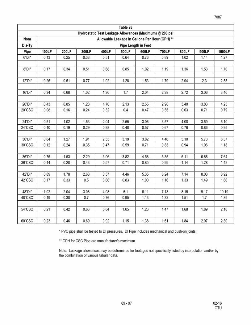
7087
69 - 97 02-16 OTU
Table 28
Hydrostatic Test Leakage Allowances (Maximum) @ 200 psi
Nom Allowable Leakage in Gallons Per Hour (GPH) **
Dia-Ty Pipe Length in Feet
Pipe 100LF 200LF 300LF 400LF 500LF 600LF 700LF 800LF 900LF 1000LF
6”DI* 0.13 0.25 0.38 0.51 0.64 0.76 0.89 1.02 1.14 1.27
8”DI* 0.17 0.34 0.51 0.68 0.85 1.02 1.19 1.36 1.53 1.70
12”DI* 0.26 0.51 0.77 1.02 1.28 1.53 1.79 2.04 2.3 2.55
16”DI* 0.34 0.68 1.02 1.36 1.7 2.04 2.38 2.72 3.06 3.40
20”DI* 0.43 0.85 1.28 1.70 2.13 2.55 2.98 3.40 3.83 4.25
20”CSC 0.08 0.16 0.24 0.32 0.4 0.47 0.55 0.63 0.71 0.79
24”DI* 0.51 1.02 1.53 2.04 2.55 3.06 3.57 4.08 3.59 5.10
24”CSC 0.10 0.19 0.29 0.38 0.48 0.57 0.67 0.76 0.86 0.95
30”DI* 0.64 1.27 1.91 2.55 3.19 3.82 4.46 5.10 5.73 6.37
30”CSC 0.12 0.24 0.35 0.47 0.59 0.71 0.83 0.94 1.06 1.18
36”DI* 0.76 1.53 2.29 3.06 3.82 4.58 5.35 6.11 6.88 7.64
36”CSC 0.14 0.28 0.43 0.57 0.71 0.85 0.99 1.14 1.28 1.42
42”DI* 0.89 1.78 2.68 3.57 4.46 5.35 6.24 7.14 8.03 8.92
42”CSC 0.17 0.33 0.5 0.66 0.83 1.00 1.16 1.33 1.49 1.66
48”DI* 1.02 2.04 3.06 4.08 5.1 6.11 7.13 8.15 9.17 10.19
48”CSC 0.19 0.38 0.7 0.76 0.95 1.13 1.32 1.51 1.7 1.89
54”CSC 0.21 0.42 0.63 0.84 1.05 1.26 1.47 1.68 1.89 2.10
60”CSC 0.23 0.46 0.69 0.92 1.15 1.38 1.61 1.84 2.07 2.30
* PVC pipe shall be tested to DI pressures. DI Pipe includes mechanical and push-on joints.
** GPH for CSC Pipe are manufacturer's maximum.
Note: Leakage allowances may be determined for footages not specifically listed by interpolation and/or by the combination of various tabular data.
7087
70 - 97 02-16 OTU
3.5. Disinfection of New Mains Utilizing Machine Chlorination.
After the new mains have successfully passed the pressure test specified in Section 3.4.3, “Hydrostatic Tests”, the San Antonio Water System will disinfect those mains shown on the plans or otherwise indicated as “Machine Chlorination”. This disinfection is to include chlorination, flushing, and placing the mains in service. All other disinfection requirements shall be accomplished by the Contractor. Disinfection by the Contractor is limited to sections of pipe less than 800 feet in length between sections.
3.5.1. Operation of Valves.
During and after disinfection of mains less than or equal to 16 inches in diameter, the Contractor shall be notified by the Inspector sufficiently in advance (2 work days) to enable the Contractor to have a competent representative present whenever valves are to be operated that will affect the pressure in any part of the work for which the Contractor is responsible.
3.5.2. Contractor's Personnel and Equipment.
The Contractor is to supply labor and equipment necessary to make all excavations required for chlorination, equipment connections, subsequent flushing, and placing the mains in service.
3.5.3. Safeguarding and Backfilling Open Holes.
The Contractor is to be responsible for safeguarding any open holes excavated or left open for flushing and disinfection purposes. Following completion of disinfection, the Contractor is to backfill such holes in accordance with appropriate provisions of Subarticle 3.3, “Backfill”.
3.5.4. Disinfection of Mains Utilizing Dry Calcium Hypochlorite.
Mains are to be disinfected with dry Calcium Hypochlorite (HTH) where shown on the plans or as directed and shall not exceed a total length of 800 feet. This method will also be followed for main repairs. Contractor shall utilize appropriate safety measures to protect personnel during disinfection operation.
3.5.5. Dosage.
The Contractor is to disinfect the new or replaced mains with Calcium Hypochlorite (HTH) of 70 percent available chlorine. Sufficient Calcium Hypochlorite (HTH) is to be used to obtain a minimum chlorine concentration of 50 ppm. The following Table 29, Chlorine Dosage, is included for the convenience of the Contractor:
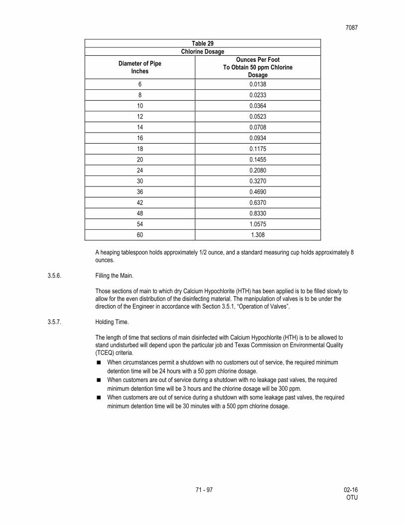
7087
71 - 97 02-16 OTU
Table 29
Chlorine Dosage
Diameter of Pipe Inches
Ounces Per Foot To Obtain 50 ppm Chlorine
Dosage
6 0.0138
8 0.0233
10 0.0364
12 0.0523
14 0.0708
16 0.0934
18 0.1175
20 0.1455
24 0.2080
30 0.3270
36 0.4690
42 0.6370
48 0.8330
54 1.0575
60 1.308
A heaping tablespoon holds approximately 1/2 ounce, and a standard measuring cup holds approximately 8 ounces.
3.5.6. Filling the Main.
Those sections of main to which dry Calcium Hypochlorite (HTH) has been applied is to be filled slowly to allow for the even distribution of the disinfecting material. The manipulation of valves is to be under the direction of the Engineer in accordance with Section 3.5.1, “Operation of Valves”.
3.5.7. Holding Time.
The length of time that sections of main disinfected with Calcium Hypochlorite (HTH) is to be allowed to stand undisturbed will depend upon the particular job and Texas Commission on Environmental Quality (TCEQ) criteria.
When circumstances permit a shutdown with no customers out of service, the required minimum
detention time will be 24 hours with a 50 ppm chlorine dosage.
When customers are out of service during a shutdown with no leakage past valves, the required
minimum detention time will be 3 hours and the chlorine dosage will be 300 ppm.
When customers are out of service during a shutdown with some leakage past valves, the required
minimum detention time will be 30 minutes with a 500 ppm chlorine dosage.
7087
72 - 97 02-16 OTU
3.5.8. Flushing.
Following the expiration of the specified holding time, the treated section of main is to be flushed thoroughly by the Contractor in accordance with the applicable provisions of Subarticle 3.4, “Flushing and Testing Mains”. Flushing is to continue until no chlorine remains detectable by taste or odor or until the chlorine residual is less than 0.3 ppm. The Contractor must make provisions for the disposal and runoff of the flushing operations in order to minimize erosion or impact to residents.
3.5.9. Preventing Reverse Flow
Valves are to be manipulated so that the strong chlorine solution in the line being treated will be flushed out of the main and will not flow back into the line supplying the water.
3.5.10. Supervision
All disinfection is to be done as be done under the general supervision of the Water System Company.
3.5.11. Additional Treatment
Should the new main fail to meet minimum public health standards for bacteriological quality after flushing, further treatment is to be as directed. If further disinfection is required, chlorination is to be done in accordance with Subarticle 3.5, “Disinfection of New Mains Utilizing Machine Chlorination”. In no case, however, is the new line to be acceptable as complete and satisfactory until the bacteriological quality of the water taken from the main meets the Standards of the TCEQ.
If an open hole is unsafe and does not have proper trench protection, owner’s chlorination crew will not chlorinate project until acceptable trench protection is provided.
3.6. Service Supply Lines
Service supply lines and fittings, meter boxes and appurtenances shall conform to material specifications and shall be installed by the contractor as specified herein, or as directed by the engineer and in accordance with plans. Service supply lines in High Pressure Zones should be installed with two strap service saddle clamps.
3.6.1. Designation of Service Supply Lines
A service supply line located between the Water main and the inlet side of the water meter is designated as a “water service line”. A service supply line located between the outlet side of the water meter to the point of connection within the limits of the Customers lot or property is designated as “Customer’s yard piping”. Services 2” and smaller are designated “small services”; services 4” and larger are designated “large services”.
Service Relays: New transfer main(s) to which services are to be relayed and are on the same side of the streets as the Customer’s meter are defined as “short relays”. New transfer main(s) to which services are to be relayed and are on the opposite side of the street from the Customer’s meter are defined as “long relays”.
Service Reconnects: New transfer main(s) to which services are to be reconnected and on the same side of the street as the old main are defined as “service reconnects”. Existing services on the opposite side of the street to the new main shall be defined as a “long reconnects”.
Service Relocates: Service Relocates are defined as services that are relocated from an alley to a side or front street. New transfer main(s) to which services are to be relocated and are on the same side of the street as the Customer’s new meter box location, are designated as “short relocates”. New transfer main(s) to which services are to be relocated and are on the opposite side of the street from the Customer’s new meter box location, are designated as “long relocates”.
7087
73 - 97 02-16 OTU
New Services: If a new main is required to be extended to provide water service for new Customers, the service lines laid to the new main shall be designated as "new services." New laid main(s) to which new services are on the same side of the street as the Customer's new meter box location, are designated as "new short services." New laid main(s) to which new services on the opposite side of the street from the Customer's new meter box location, are designated as "new long services."
New Un-metered Services: New Un-metered services are defined as services that are installed on existing mains or new mains to provide service to Customers platted vacant lots. Where the new main or existing main to which new un-metered services are being installed is on the same side of the street as the Customer's new or existing meter box location, (Inspector to set location of new meter box if no existing meter box is set), the services to be laid are designated "new un-metered short services." Where the new main or the existing water main to which new un-metered services are installed is on the opposite side of the street from the Customer's new or existing meter box location, (Inspector to set location of new meter box if no existing meter box is set), the services to be laid are designated "new un-metered long service". New un-metered long services and new un-metered short services will not include "Customer's yard piping" and no meter will be set.
Tap Holes: Tap holes are defined as excavations at existing mains, which are required in association with replacements of water service lines by pulling, boring or jacking operations.
All backfill material shall be as specified for main and service line trench excavation.
For service lines and tap holes, payment for bedding, initial backfill and secondary backfill shall be included in the various sizes of each service placed.
Service Line Installation: Unless otherwise notified, service relays, service reconnects, service relocates and new services shall be installed as described herein, and in plans. Unless otherwise indicated, existing meter and meter box relocation shall be included in the service line installation.
All service line installation shall include a dielectric union to be installed within the meter box on the outlet side of the meter, as shown in plans.
Cutting, excavation, backfill and replacement of pavement shall be done as specified herein and in accordance with applicable sections of this specification and the contract documents. The minimum trench width for small service lines shall be 8 inches, while the minimum trench width for large service Lines shall be the nominal pipe diameter plus 16 inches, except when specified otherwise by the Engineer. For ¾” to 2" Service lines, minimum bury depth shall be 3 feet. For services greater than 2”, minimum depth of bury shall be 4 feet.
All service lines shall be installed in accordance with plans, and specifications, except that two strap service saddle clamps shall be installed for all tap connections made on water mains located within boundaries of Pressure Zones (formally known as Service Levels) 9 through 16.
The Contractor shall use precaution to protect and preserve the polyethylene wrap around Ductile-Iron (DI) water mains when installing service corporations. The required method is, wrap pipe tape around the pipe, over the polywrap, in the area to be tapped. The tap shall be made through the tape and polywrap. It is not necessary to remove and replace polywrap. All exposed pipe, corporation and the first three feet of the service, shall be wrapped and taped to achieve a complete seal. In addition, a sand envelope shall extend over and around the connection to a depth of 8 inches above the main.
Small service lines shall be embedded in sand in accordance with specification
When approved by the Construction Inspector, the Contractor may lay the new service line from the corporation stop to the curb stop or angle valve. Upon completion, the Contractor shall isolate the new service line by closing the curb stop or angle valve until the meter box is set.
7087
74 - 97 02-16 OTU
Splicing: A long service line single splice may be permitted by means of a 3-part compression or flared coupling only when approved in advance by the Engineer, provided the location of the splice is not under pavement or concrete. The segment added is required to be the same material as the existing service line, unless otherwise directed by the Engineer. Splicing short service lines will not be permitted.
Boring or Jacking Service Lines: Service lines which cross paved streets may be installed at the Contractor's option by boring or jacking operations. Where it becomes necessary to widen the main trench section to accommodate a bore pit, such widening shall not extend more than one additional foot into the traffic side of the street.
Tapping Asbestos Cement (AC) Water Mains: All necessary service line tapping of AC pipe shall be completed during the period immediately before or after hydrostatic pressure testing operations so that subsequent flushing will maximize the elimination of contaminants associated with the tapping process.
Tapping of AC pipe must be done in accordance with manufacturers’ recommendation and done only with tap machine having a built in flush valve and the flush valve must be open during the entire procedure.
Abandonment of Service Lines: The Contractor shall accomplish all cutting, capping, and plugging necessary to isolate new service lines transferred to new and existing mains from those abandoned, including service lines designated on the plans as "tap plug" and "tap kill." The corporation stop for an abandoned service line tapped on a ferrous main shall be removed, and the tap at the main shall be plugged with an appropriately sized brass plug. For a non-ferrous main, the corporation stop shall not be removed from the main. Instead, the corporation stop shall be closed and the flared nut shall be removed from the corporation stop. After the appropriately sized copper disc is inserted inside the flared nut, replace the flared nut on the corporation stop. The Contractor shall salvage copper service line tubing, brass fittings, and other materials as directed by the Inspector and return them to the Owner.
Tapping PVC (C-900): Tapping of PVC must be done in accordance with Uni-Bell procedures. Direct Tapping will not be allowed. All drill cutting tools must be the "shell type" with internal teeth or double slots which will retain the coupon.
The shell cutters must be designed for C-900 pipe, thus having sufficient root depth to handle the heavier walled pipe.
Small Service Lines: Copper tubing shall be used for ¾” through 2" service lines. Brass fittings for ¾” and 1" service lines shall be of the flared or compression type for the use with Type 'K' soft annealed copper tubing. Brass fittings for 1½" and 2" lines shall be of the flared or compression type for use with type 'K' soft annealed copper tubing, except as modified by this specification.
Copper tubing shall be cut squarely by using an approved cutting tool and by avoiding excessive pressure on the cutting wheels which might bend or flatten the pipe walls. Following the copper tubing cut, but before flaring, a reamer shall be used to remove the inside rolled lip from the tubing. Flared ends shall be expanded by the use of a flaring tool using care to avoid splitting, crimping, or overstressing the metal. Pipe adjacent to the fittings shall be straight for at least 10 inches. Bending of tubing shall be accomplished by using an appropriate sized bending tool. No kinks, dents, flats, or crimps will be permitted, and should such occur, the damaged section shall be cut out and replaced. When compression fittings are used, the copper tubing shall be cut squarely prior to insertion into the fitting Final assembly shall be in accordance with the manufacturers recommendations.
Small Service Lines on New Mains: Installation of new copper service lines shall consist of all excavation through miscellaneous material encountered; trench excavation protection; drilling and tapping the new main with an approved tapping machine; setting the curb stop or angle valve at the meter; laying the new copper service line at the specified depth between the main and the meter and its tie-in at the corporation and the curb stop or the angle valve; relocating the existing meter and installing a new meter box where required in accordance with this specification, herein; backfilling the trench with approved selected material and disposal of surplus excavated material; capping the tap hole with asphalt treated base, including the outer limits of the
7087
75 - 97 02-16 OTU
main trench line with service line trench; cutting and replacing pavements, curbing and sidewalks of all types over the limits of the main line trench and the completed service line trench.
Reconnecting Service Lines: Both old and new water mains at existing service line connections as shown on the plans shall be exposed. The old main shall be exposed for the purpose of gaining access to the existing service corporation stop and the new main for the purpose of installing the new corporation stop. The new main shall be exposed for the purpose of being drilled and tapped with an approved tapping machine, a new corporation stop installed under pressure, and the trench extended laterally to expose a sufficient length of the existing service line to provide slack to bend it to position for tying to the new corporation stop. After suitable notification to the Customer, the Contractor shall “kill” the existing service by closing the corporation stop, removing the existing flare nut, inserting the existing flared nut on the corporation stop if the main is non-ferrous, or plugging the existing service line at the main if the main is ferrous. The Contractor shall then immediately open the stop and restore water service to the Customer. Where it is not possible to obtain sufficient length in the existing service to tie directly to the new main, at the direction of the Engineer, the Contractor shall splice the necessary length of new tubing and tie it to the existing service by means of a compression coupling at a point as close as practicable to the new main.
Cutting and bending of the tubing, introduction of slack to compensate for soil movement, and completion of the installation shall be as specified in this specification.
Where old and new mains are on opposite sides of the street, service lines may be installed under the street pavement by boring rather than trenching.
Relaying Service Lines: The existing or new mains shown on plans shall be exposed opposite location stakes placed on site at the direction of the Engineer. The existing or new main shall; be drilled and tapped with an approved tapping machine, a new corporation stop installed, and the trench extended laterally to the location specified for the meter box. The existing meter shall be reset and the meter box and base shall be installed at its staked location and perpendicular to the corporation stop in the water main. The meter box location shall not vary more than 24 inches in any direction from its staked location. The service line shall be installed with sufficient slack to compensate for soil movement. Where the location of the existing meter is not changed, the new service line shall be extended from the main to the existing meter, a new curb stop installed at the end of the service line, and connected to the inlet side of the meter. If disturbed, the existing meter box shall be reset to correct grade. Long service relays may be placed under the street pavement by boring or jacking rather than trenching.
Single Service Line - Dual Meters: The single service line - dual meter installation shall consist of a 1" copper service line reducing to two ¾” copper service lines at a tee which shall be set in line with the front edge of meter boxes for ⅝” and ¾” meters. A single service line with dual meters shall be installed in those new residential developments where new ⅝” and ¾” meters are required and in main replacement work where it is necessary to change the location of existing ⅝” and ¾” meters. Single service line - dual meter materials and installation requirements shall conform to requirements established herein.
Small Service Lines on Existing Mains: The work involved in the installation of new copper service lines on existing mains shall consist of jacking, boring, tunneling, and, where authorized, open trench operations all excavation through whatever material encountered; trench excavation protection; using the existing corporation when approved by the Engineer; tapping the existing main and installing the new corporation and setting the curb stop or angle valve at the meter; relocating the existing meter and installing a new meter box where required in accordance with this specification; abandoning the existing corporation stop, removing the existing flared nut, inserting inside the existing flared nut an appropriately sized copper disc and replacing the existing flared nut on the corporation stop if the main is non-ferrous, or plugging the existing service line at the main if the main is ferrous; installing the new service line at the same grade as the existing service line or at the specified grade between the main and the existing meter and its tie-in at the corporation and the curb stop; disposal of surplus excavated material; capping the tap hole with asphalt treated base including the outer limits of the main line trench and the service line trench; cutting and replacing all surfaces of whatever type encountered over the completed service line trench; restoration of the site.
7087
76 - 97 02-16 OTU
Large Service Lines: DI pipe and cast-iron fittings used for metered service lines and non-metered fire service lines larger than 2” shall be installed in accordance with the applicable provisions of this specification, except where otherwise approved by the Engineer.
Large Service Lines on New Mains: Work involved in the installation of a new metered service lines and non-metered fire service lines shall consist of all excavation through whatever material encountered; trench excavation protection, installing tees, pipe and fittings of various sizes including main line and service line valves, valve boxes, DI pipe, fittings, in accordance with plans and reaction block required; backfilling with approved selected material; cutting and replacing pavements, curbing, and sidewalks of all types over the limits of the main line trench and the completed DI service line.
Large Service Lines on Existing Mains: The work involved in the installation of the new metered service lines and non-metered fire service lines shall consist of all excavation through whatever material encountered, trench excavation protection, cutting-in tees and installing tapping sleeves and valves, pipe and fittings of various sizes including main line and service valves; valves boxes, DI pipe, fittings and reaction block required; backfilling with approved selected material; cutting and replacing pavements, curbing, and sidewalks of all types over the limits of the main line trench and the completed DI service line.
3.6.2. Meter Boxes
Physical movement of existing meters and meter boxes to new locations may be required where service lines are transferred to new mains in conjunction with main replacement work. Unless specified otherwise, the Contractor shall move existing meters and meter boxes and reconnect and adjust customer's yard piping as part of transferring service lines. A dielectric coupling PVC (schedule 80) shall be installed within the meter box between the meter and the customer's yard piping.
Round and oval meter boxes with round covers shall be salvaged and returned to the Owner by the Contractor. The Contractor shall also replace the salvaged meter boxes with the new, appropriately styled oval plastic meter box with oval cover, or rectangular meter box. Unless otherwise specified, the old service line shall be abandoned after the existing meter has been reset in the existing or new meter box.
Where meter boxes are installed in sidewalks or driveways, the Contractor shall install a number one meter box (2 pieces) as shown in the Specification and plans.
New meters will be set by the Owner where mains are extended and new services lines are installed for new or initial customer service. In lieu of the new meter, the Contractor shall furnish and install a meter template in accordance with plans .
Meter and meter box configuration, shall have the meter set horizontal, approximately 6 inches below the top of meter box, so that the meter is above the bottom of the meter box and in line with the meter box lid opening. The top of the meter box shall be flush with the existing ground surface. All excess soil above the meter coupling, meter flange and meter nuts inside the meter box shall be removed so that the meter register is clearly visible. The Contractor shall exercise special precautions during excavation at the existing meter location in order to minimize the disturbance of the customer's yard piping. However, if the existing meter elevation is low, the Contractor shall raise the existing meter to conform to the correct configuration indicated herein. Adjustment of meter to proper grade is incidental to the construction and will not be paid for separately.
Where required, pressure reducing valves shall be installed by the customer in accordance with the Uniform Plumbing Code and shall be placed beyond the outlet side of the meter, but not within the Owner's meter box. The pressure reducing valve shall be the property of the water user who will be responsible for its installation, maintenance, and replacement as required.
The meter box adjustment shall not exceed 10 linear feet from the existing box.
7087
77 - 97 02-16 OTU
3.6.3. Water Service for Fire Lines
Start of Work: Three working days notice will be given to the assigned Inspector prior to start of a project after permit has been issued. The Contractor shall start his work at a tie-in or point designated by the Engineer. Pipe shall be laid with bell ends facing in the direction of laying, unless otherwise authorized or directed by the Engineer. All valves and fire hydrants must be installed as soon as pipe laying reaches their established location. Pipe shall be installed to the required lines and grades with fittings, valves, and hydrants placed at the required locations. Spigots shall be centered in bells or collars, all valves and hydrant stems shall be set plumb, and fire hydrant nozzles shall face as shown on the plans or as directed by the Engineer. No valve or other control on the existing system shall be operated for any purpose by the Contractor unless a representative of the San Antonio Water System is present.
Crossing Other Underground Lines:
New fire line services crossing any other utilities shall have a minimum of 48 inches of cover over the top of the pipe unless otherwise waived or modified by the Engineer. Excavation around other utilities shall be done by hand for at least 12 inches all around. Any damage to other utilities shall be reported to the governing entity/owner of said utility as well as the Inspector.
Pipe Grade:
Fire line services shall have a minimum of 48 inches of cover for mains 16” and below, and 60 inches for mains 20” and above, over the top of the pipe unless otherwise waived or modified by the Engineer. Pipe grades shall be as required by the plans or as directed by the Engineer. Grades shall be met as specified. Precautions shall be taken to insure that the pipe barrel has uniform contact with the Modified Grade 5 for its full length except at couplings. Couplings shall not be in contact with the original trench bottom prior to backfilling. Modified Grade 5 material shall be placed under the coupling and compacted by hand prior to backfilling so as to provide an even bearing surface under the coupling and pipe. Changes in grade shall be made only at joints.
Modified Grade 5 Materials:
Prior to placing pipe in a trench, the trench shall have been excavated to the proper depth as required of these specifications. Approved imported materials or Engineer approved materials selected from suitable fines derived from the excavation shall be smoothly worked across the entire width of the trench bottom to provide a supporting cushion.
Structures to Support Pipe:
Where as the bottom of a trench at subgrade consist of material that is notably unstable by the Engineer and cannot be removed and replaced with approved material may be properly compacted in place to support the pipe. The Contractor shall also construct a foundation for the pipe consisting of piling, concrete beams, or other supports in accordance with plans prepared by the Engineer.
Lowering Materials into Trench:
Proper implements, tools, and facilities satisfactory to the Engineer shall be provided and used by the Contractor for the safe and convenient completion of work. All pipe, fittings, valves, and hydrants shall be carefully lowered into the trench piece by piece, by means of a derrick, ropes, or other suitable tools or equipment in such a manner as to prevent damage to water service materials and protective coatings and linings. Under no circumstances shall water service materials, pipes, fittings, etc., be dropped or dumped into the trench. Extreme care shall be taken to avoid damaging polywrap films. No chains or slings shall be allowed unless the entire sling is wrapped with a protective nylon web sock.
Laying of Pipe:
7087
78 - 97 02-16 OTU
Every precaution shall be taken to prevent foreign material from entering the pipe during its installation. Under adverse trench conditions or otherwise required by the Engineer, a heavy, tightly woven canvas bag of suitably sized shall be placed over each of the pipe.
The Canvas bag shall be left in place until a connection is made to the adjacent pipe. The interior of each pipe shall be inspected for defects, and the pipe shall be rejected if any defects are found.
After placing a length of pipe in the trench, the jointed end shall be centered on the pipe already in place, forced into place, brought to correct line and grade, and completed in accordance with the requirements of these Specifications. The pipe shall be secured in place with approved backfill material tamped around it. Pipe and fittings which do not allow a sufficient and uniform space for joints shall be rejected and shall be replaced with pipe and fittings of proper dimensions. Precautions shall be taken to prevent dirt or other foreign matter from entering the joint space.
At times when pipe laying is halted, the open end of pipe in the trench shall be closed by a watertight plug or other means approved by the Engineer. Pipe in the trench which cannot temporarily be joined shall be capped or plugged at each end to make it watertight. This provision shall apply during all periods when pipe laying is not in progress. Should water enter the trench, the seal shall remain in place until the trench is pumped completely dry. The Contractor shall provide all plugs and caps of the various sizes required.
Deviations in Line or Grade:
Wherever obstructions not shown on the plans are encountered during the progress of the work and interfere to an extent that an alteration in the plan is required, the Construction Inspector shall have the authority to change the plans and direct a deviation from the line and grade or to arrange with the owners of the structures for the removal, relocation, or reconstruction of the obstructions. Any deviation from the line shall be accomplished by the use of appropriate bends unless such requirement is specifically waived by the Construction Inspector.
Whenever it is necessary to deflect pipe from a straight line, the deflection shall be as directed by the Construction Inspector and as described herein. In no case shall the amounts exceed those shown in Table 19 "Maximum Deflections of Ductile-Iron Pipe" for ductile-iron pipe
Cutting Pipe:
The cutting of pipe for inserting valves, fittings, or closure pieces shall be accomplished in a neat manner so as to produce a smooth end at right angles to the axis of the pipe. The recommendations of the pipe manufacturer shall be strictly followed by the Contractor. Only qualified and experienced workmen shall be used and, under no circumstances, shall a workman not equipped with proper safety goggles, helmet and all other required safety attire be permitted to engage in this work.
Asbestos-Cement (AC):
No field cutting will be allowed on asbestos cement pipe. Installation of fire line services to AC pipe mains shall be accomplished by removing one full joint of AC pipe and replacing with appropriate PVC or Ductile Iron pipe and fittings. All cuts made on ductile-iron pipe shall be done with a power saw. The cuts shall be made at right angles to the pipe axis and shall be smooth. The edges of the cut shall be finished smoothly with a hand or machine tool to remove all rough edges. The outside edge of pipe should be finished with a small taper at an angle of about 30 degrees. Solid sleeves or cast couplings shall be allowed on precast/prefab vaults only. All other fire line services shall be installed with full joints of pipe.
Joint Assembly:
Rubber Ring Joints: The installation of pipe and the assembly of rubber ring joints for Ductile-Iron pipe
shall conform to the pipe manufacturer's assembly instructions. The method of inserting spigot ends of
pipe in bells or collars known as "stabbing" shall not be permitted. Spigot ends of pipe must be properly
inserted in the joint by means of suitable pushing/pulling devices or a manufacture approved method.
7087
79 - 97 02-16 OTU
Mechanical Couplings: Mechanical couplings shall be assembled and installed according to the
standards recommended by the manufacturer.
Mechanical coupling consists of a cylindrical steel middle ring, two steel follower rings, two rubber
compound gaskets, and a set of steel bolts. The middle ring is flared at each end to receive the wedge-
shaped gasket which is compressed between the middle ring flare and the outer surface of the pipe by
pressure exerted on the follower rings through the bolt circle.
Prior to the installation of the mechanical coupling, the pipe ends shall be cleaned by wire brush or other
acceptable method to provide a smooth bearing surface for the rubber compression gasket. The pipe
shall be marked to align the end of the coupling which will center it over the joint. After positioning, the
nuts shall be drawn up finger tight. Uniform pressure on the gaskets shall be applied by tightening
alternate bolts on the opposite side of the circle in incremental amounts. Soap and final tensioning shall
be accomplished with a torque wrench and in a matter similar to the tightening procedure after 15
minutes.
Restrained Joints: Restrained Joints shall be installed as shown on the plans or as directed by the
Construction Inspector. Installation shall conform to the manufacture’s recommendations.
3.7. Installation of the Nonmetallic Pipe Detection System.
The nonmetallic pipe detection system is to be installed concurrently with the proposed pipe placement. Tracer wire shall be utilized for location purposes and taped directly to the pipe. The tracer wire shall be solid core (14 gauge insulated), and shall be taper to the main in 10-inch increments. Wire shall also come up to the top of valve extensions and fire hydrant stems, as directed by the Water System Inspector.
3.8. Double Line Stop With Bypass
3.8.1. Description of Procedure
The Line-Stopping procedure is a means of temporarily plugging a pressurized pipe without disrupting pressure or service upstream of the Line-Stop. A Pressure Tap is first made into the main, allowing insertion of the Line-Stop plugging special Line-Stop fitting, the temporary valve can be later recovered after the plugging head has been removed from the main. The sequence consists of sixteen steps, two of which must be accomplished prior to placing orders for Line-Stop materials.
For Concrete pipe - determine from engineering, and/or manufacturers' records:
Make
Specification
Age
Cross Sectional Dimensions (cylinder reinforcing/pre-stressed, core and coating)
Prior to ordering material: Excavate, dewater, expose and clean the exterior of the main at location of Tap(s). If main is damaged; or if utilities will interfere with fittings, support/reaction blocking, or equipment; move location up or downstream to structurally sound pipe.
Caliper O.D. of all mains to determine ovality
Verify wall thickness and interior condition.
Remove outer coating and prepare a template of cylinder contours. This must be accomplished at the
point where Pressure Tap(s) is to be installed.
Backfill, restore as necessary.
Upon fitting delivery, re-excavate; dewater. Assemble split Line-Stop fitting(s) to the main.
7087
80 - 97 02-16 OTU
Pressure test per Engineer's specs.
Mount temporary tapping valve(s) to Line-Stop fitting(s).
Mount tapping machine; open valve; pressure tap; retract cutter; close temporary valve, remove tapping machine.
Mount Line-Stop machine, open temporary valve; insert Line-Stop plugging head into main.
If two or more Line-Stops; insert downstream plugging head first.
NOTE: No flow in main greater than 1 fps for a single (3 fps for a double) at time plugging head is
inserted into main.
Test for shutdown at drain nozzle.
Cut downstream main. Install required fittings.
Retract Line-Stop plugging head(s) close temporary valve. Remove Line-Stop machine.
Install completion machine; open valve.
Insert completion plug into nozzle of Line-Stop fitting.
Remove completion machine and temporary valve.
Repeat Par. K thru M at other Line-Stop fitting(s).
Install blind flange(s) into nozzle of Line-Stop fitting(s) and into drain fitting(s).
3.8.2. Interruption of Flow
The existing mains cannot be shut down or taken out of service. To ensure that the entire operations shall be accomplished without interruption of water service or flow, the installation shall be accomplished by Contractor personnel skilled and experienced in the procedures specific to Line-Stops of this size.
3.8.3. Reduction of Pressure
The entire operation of making the Tap(s) shall be accomplished with the line pressure operating at no more than the safety limit established by mathematical calculation of the hoop stress of the unsupported cylinder with the reinforcing (pre-stressed) wires removed. A safety factor of 80% of yield is normally used. This calculation will determine the maximum operating pressure at the time of the material installation and the Tap.
3.8.4. Preliminary Field Inspection of Mains
Dimensional, specification, and other data regarding the existing mains have been taken from records, many of which are old and/or inadequate. These data have not been verified by field inspections. Many of these mains consist of very old concrete pipe which may contain dimensional and structural flaws. In addition, it is anticipated that exterior main conditions, service connections, or presence of adjoining utilities may require relocation of proposed Taps.
It is necessary to know the exact main O.D., ovality, and cylinder diameter before Line-Stopping fittings can be manufactured.
Prior to ordering material, Contractor shall excavate at each proposed location and caliper the header O.D. along at least four (4) diameters to determine ovality.
7087
81 - 97 02-16 OTU
Contractor shall determine main wall thickness, uniformity and structural integrity by means of ultrasonic testing. Data shall be submitted to Engineer.
Contractor shall expose a section of the internal steel cylinder at the Pressure Tap location and prepare a template showing the actual contour of that cylinder. Contractor shall apply Portland cement mortar to the exposed cylinder, filling the recess flush with the O.D. of the main. Mortar will be allowed to harden before backfilling.
If, in Engineer's opinion, the proposed location is unsatisfactory he will direct excavation at another site. Excavating, dewater, inspections, backfill and restoration will be separate pay items.
3.8.5. Installation of Line-Stop Fitting, Concrete Steel Cylinder Pipe
Note: Cylinder shall have been exposed and inspected by Contractor, per Section 3.8.4, prior to ordering Line-Stop fitting. Contractor shall power wire brush and grind the exterior of the main to remove any debris, corrosion deposits, or other surface irregularities that might interfere with proper seating and sealing of each tapping fitting against each main. Any structural defects in main, service connections appurtenances, adjacent utilities, etc. that could interfere with tapping installation shall be immediately reported to Engineer.
Inspection: Contractor shall fit upper and lower saddle assemblies to main, thoroughly checking for proper fit to main.
Assembly to Main: Under no circumstances shall Contractor attempt to force, reshape or bend saddle plates by excessive tightening of saddle studs while Line-Stop fitting is assembled around the main.
Any retrofitting shall be accomplished with the fitting removed from the main.
Any damage to fitting, accessories, or main shall be repaired at Contractor's expense to the satisfaction
of Engineer.
Assemble of Saddle: Upper and lower saddle assembly shall be drawn up against the main to compress
gaskets (SP1.6.F).
The exterior surface of the nozzle half of the main be wetted thoroughly by pouring water into the grout
hoppers.
Grouting: Grouting material shall be a rich, high early strength, non-shrink, Portland cement mixture. Its' consistency shall be fluid enough to allow it to flow between the saddle plate and the surface of the main.
Upper saddle plate shall be grouted by pouring mixture into grout hoppers and vibrating saddle plate to
eliminate air pockets.
After grout has taken initial set, draw studs shall be tightened as necessary.
Exposure of Cylinder: Contractor shall chip exterior concrete coating from main to expose reinforcing cages or pre-stressed wires. Any cages not touching cylinder may be cut by torch or cold chisel. Contractor shall exercise extreme caution to avoid damage to cylinder. NOTE: Pressure in line may have to be reduced during installation of Line- Stop Fitting.
Line-Stop Flange/Nozzle Gland Assembly: Contractor shall thoroughly clean and prepare the surface of the cylinder to insure a pressure-tight seal to the gland gasket. Surface imperfections such as weld seams shall be carefully filed.
Pressure Test: Using a tapped blind flange, Contractor shall pressure test the Line-Stop fitting to verify satisfactory gland/cylinder seal. Test pressure shall not exceed recommended amount to avoid collapsing the cylinder and liner.
Nozzle Grouting: The entire volume between the Line-Stop nozzle and the anchor neck shall be filled with grouting material per Section 3.8.5 Contractor shall vibrate the nozzle to eliminate air pockets.
7087
82 - 97 02-16 OTU
Nozzle grout must thoroughly set before mounting temporary valve.
3.8.6. Thrust and Support Blocking
Prior to mounting temporary valve and pressure tapping machinery, Contractor shall install concrete thrust and support blocking as shown on the plans. Blocking shall reach a minimum cure strength specified by Engineer before any valves or machinery shall be mounted onto the Line-Stop fitting.
3.8.7. Cutting Operation
Drilling equipment shall be in good condition, and equipped with power drive to insure smooth cutting and to minimize shock and vibration. Cutting equipment shall be carbide tipped and capable of being renewed without removal from jobsite.
Tapping Equipment: Shall be mounted and blocked to temporary valve and the entire assembly pressure tested.
Upon acceptance from Engineer the Pressure Tap may be performed.
Upon completion of Tap, machine shall be retracted, with coupon, into its' housing, temporary valve
closed and equipment removed.
3.8.8. Line-Stop Machinery
The equipment shall consist of a folding plugging head that contains an elastomer sealing element. The plugging head is advanced into and from the main by means of a linear actuator. When retracted, the plugging head and carrier are housed in an adapter, bolted pressure tight between the tapping valve and the actuator.
Plugging Head: The diameter of the plugging head shall be the same as the pipe size. Plugging head shall open mechanically and sealing element is in full contact with the bore of the main when fully seated.
Sealing Element: The element shall be monolithically molded from a suitable polyurethane compound. The element shall be flat in a plane perpendicular to the flow in the main and seal against the I.D. of the main when plugging head is in the full open position.
3.8.9. Completion
The completion of the Line-Stopping shall include the installation of the Completion Plug and a Blind Flange.
Completion Plug: Test of completion plug sealing shall be accomplished through bleed-off in machinery housing.
Removal: Temporary valve shall be removed and installation of blind flange shall be completed.
3.9. High Pressure Zone
Work performed for construction of a high pressure water distribution system, including water mains, services, fire hydrants, and all related appurtenances, is to be done in accordance with this specification. This subsection applies solely to the construction of high pressure water systems and shall govern when in conflict with of subsections of this specification.
High Pressure Systems
Each water distribution system that furnishes water in Pressure Zone 9 through Pressure Zone 16 shall be designated as a high pressure system. The static water pressure in each in each Service Level shall be not less than 35 psi nor exceed 175 psi with no fire hydrants in use.
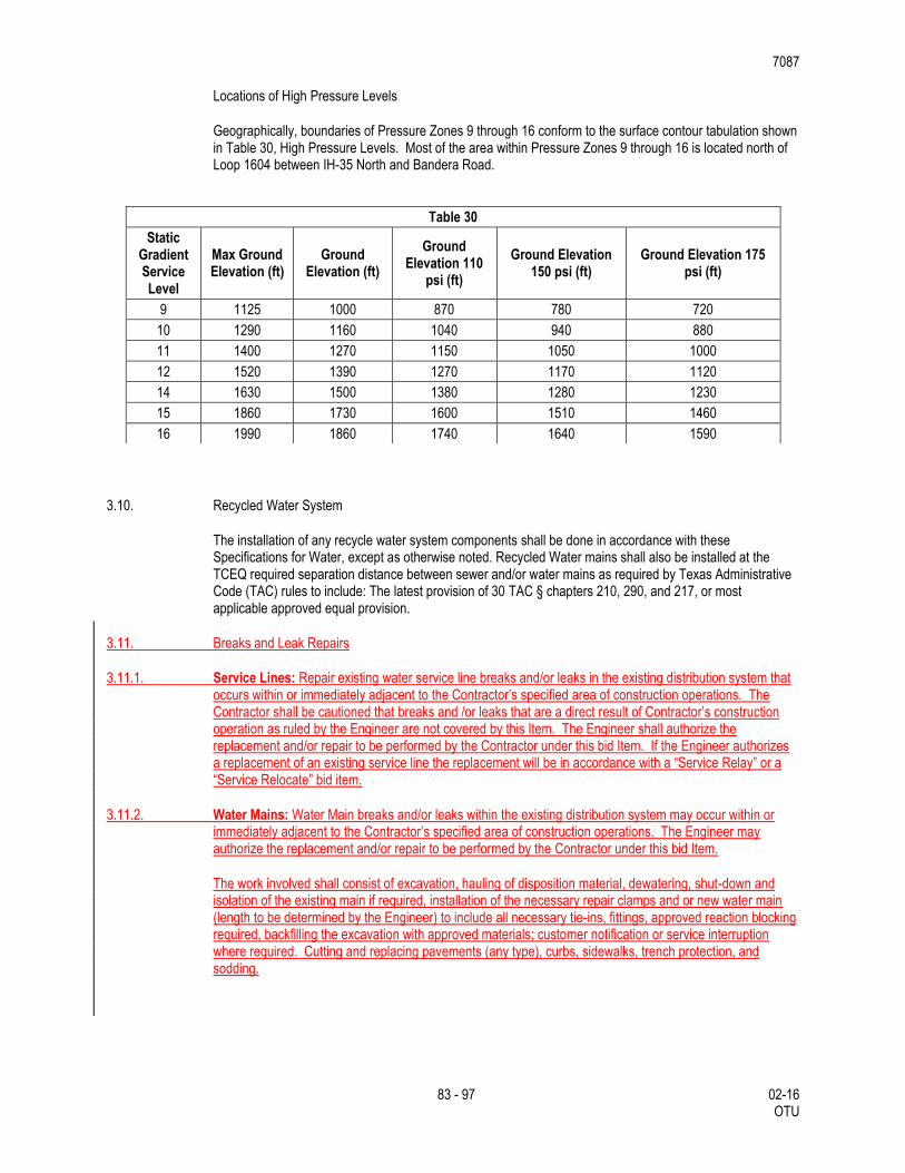
7087
83 - 97 02-16 OTU
Locations of High Pressure Levels
Geographically, boundaries of Pressure Zones 9 through 16 conform to the surface contour tabulation shown in Table 30, High Pressure Levels. Most of the area within Pressure Zones 9 through 16 is located north of Loop 1604 between IH-35 North and Bandera Road.
3.10. Recycled Water System
The installation of any recycle water system components shall be done in accordance with these Specifications for Water, except as otherwise noted. Recycled Water mains shall also be installed at the TCEQ required separation distance between sewer and/or water mains as required by Texas Administrative Code (TAC) rules to include: The latest provision of 30 TAC § chapters 210, 290, and 217, or most applicable approved equal provision.
3.11. Breaks and Leak Repairs
3.11.1. Service Lines: Repair existing water service line breaks and/or leaks in the existing distribution system that occurs within or immediately adjacent to the Contractor’s specified area of construction operations. The Contractor shall be cautioned that breaks and /or leaks that are a direct result of Contractor’s construction operation as ruled by the Engineer are not covered by this Item. The Engineer shall authorize the replacement and/or repair to be performed by the Contractor under this bid Item. If the Engineer authorizes a replacement of an existing service line the replacement will be in accordance with a “Service Relay” or a “Service Relocate” bid item.
3.11.2. Water Mains: Water Main breaks and/or leaks within the existing distribution system may occur within or immediately adjacent to the Contractor’s specified area of construction operations. The Engineer may authorize the replacement and/or repair to be performed by the Contractor under this bid Item.
The work involved shall consist of excavation, hauling of disposition material, dewatering, shut-down and isolation of the existing main if required, installation of the necessary repair clamps and or new water main (length to be determined by the Engineer) to include all necessary tie-ins, fittings, approved reaction blocking required, backfilling the excavation with approved materials; customer notification or service interruption where required. Cutting and replacing pavements (any type), curbs, sidewalks, trench protection, and sodding.
Table 30
Static Gradient Service Level
Max Ground Elevation (ft)
Ground Elevation (ft)
Ground Elevation 110
psi (ft)
Ground Elevation 150 psi (ft)
Ground Elevation 175 psi (ft)
9 1125 1000 870 780 720
10 1290 1160 1040 940 880
11 1400 1270 1150 1050 1000
12 1520 1390 1270 1170 1120
14 1630 1500 1380 1280 1230
15 1860 1730 1600 1510 1460
16 1990 1860 1740 1640 1590
7087
84 - 97 02-16 OTU
4. MEASUREMENT
This Item will be measured as follows: “Pipe Water Main (DI)”, “Pipe Water Main (PVC)”, “Pipe Water Main (PVC Casing) (Open Cut)”, and “Pipe Water Main (Steel Casing) (Open Cut)” for water pipe of the various sizes shown on the plans, will be measured by the linear foot as follows: From the centerline intersection of runs and branches of tees to the end of the valve of a dead-end run.
Between the centerline intersections of runs and branches of tees, and where the branch is plugged for future connection, the measurement will include the entire laying length of the branch or branches of the fitting.
The measurement of each line of pipe of each size will be continuous and is to include the full laying lengths of all fittings and valves installed between the ends of such line except that the laying lengths of reducers will be divided equally between the connected pipe sizes. Lines leading to a tapping connection with an existing main will be measured to the center of the main tapped.
“Fire Lines” will be measured by the linear foot for each size and type from the centerline intersection of the fire line with the main distribution line to the property line. The measurement will include the entire laying length of the branch or branches of the fitting and valves. Line leading to a tapping connection with an existing main will be measured to the center of the main tapped.
“Jacking or Boring (Water Main)” will be measured by the linear foot of bore or tunnel as measured from face to face of jacking pits.
Carrier pipe used in bores and tunnels or backed into place will be measured by the linear foot of pipe installed from end to end of pipe to the limits shown on the plans
Carrier pipe installed in open trenches, where required by the plans, will be measured by the linear foot of pipe installed from end to end of pipe to the limits shown on the plans.
Casing or liners used in bores and tunnels, where required by the plans, of the size and material required will be measured by the linear foot actually installed in accordance with plans.
Casing installed in open trenches, where required by the plans, of the size and material required will be measured by the linear foot actually installed in accordance with plans.
Split Steel Casing installed in open trenches, where required by the plans, of the size and material required will be measured by the linear foot actually installed in accordance with plans.
“Butterfly Valve and Box (Complete)” will be measured as each assembly of the various sizes installed.
“Gate Valve and Box (Complete)” will be measured as each assembly of the various sizes installed to finished grade.
“Cut-in Butterfly Valve and Box (Complete)” will be measured as each assembly of the various sizes installed to finished grade.
“Cut-in Gate Valve and Box (Complete)” will be measured as each assembly of the various sizes installed to finished grade.
“Tapping Sleeve, Valve and Box (Complete)” will be measured as each assembly of the various sizes installed.
“Cut-in Tee (Complete)” will be measured as each assembly of the various sizes of cast-iron tees cut-in to the existing water main.
7087
85 - 97 02-16 OTU
“Adjust Existing Valve Box” will be measured as each assembly adjusted to correspond to finish grade.
“Concrete Encasement, Concrete Cradles, Concrete Saddles and Concrete Collars” for pipe will be measured by the cubic yard as dimensioned on the plans, 6’ in depth measured from the outside pire diameter (0.0) or as directed. Reinforcing if required will not be measured for payment.
“Fire Hydrant with 6-in. Valve and Box” will be measured as each fire hydrant installed. Also included will be sufficient pipe, valve and fittings.
“Fire Hydrant with Tapping Sleeve, 6-inch Valve and Box” will be measured as each fire hydrant including the various sizes of tapping sleeves, valves, and boxes installed.
“Relocate Fire Hydrant” will be measured as each fire hydrant relocated.
“Permanent Blow-off (Complete)” will be measured as each assembly of the various sizes installed.
“Temporary Blow-off (Complete)” will be measured as each assembly of the various sizes installed.
“Automatic Air Release Valve (Complete)” will be measured as each assembly of the size installed.
“Trench Excavation Protection” and “Joint Trench Excavation Protection” will be measured by the linear foot along the centerline of trench where the depth of trench exceeds 5-ft.
“Tie-In (Complete)” will be measured as each of the various sizes and types completed.
“New Short Service” will be measured as each of the various sizes and types of new service lines installed.
“New Long Service” will be measured as each of the various sizes and types of new service lines installed.
“New Unmetered Short Service” will be measured as each of the various sizes and types of new unmetered service lines installed.
“New Unmetered Long Service” will be measured as each of the various sizes and types of new unmetered service lines installed.
“New Unmetered Long Service (Sleeved)” will be measured as each of the various sizes and types of new unmetered service lines installed.
“Reconnect Short Service” will be measured as each of the various sizes of service lines reconnected.
“Reconnect Long Service” will be measured as each of the various sizes of service lines reconnected.
“Relay Short Service” will be measured as each of the various sizes of service lines re-laid.
“Relay Long Service” will be measured as each of the various sizes of service lines re-laid.
“Relay Long Service (Sleeved)” will be measured as each of the various sizes of service lines re-laid.
“Relocate Short Service” will be measured as each of the various sizes of service lines relocated.
“Relocate Long Service” will be measured as each of the various sizes of service lines relocated.
“Relocate Existing Meter and Existing Meter Box” will be measured as each assembly relocated and customer's service reconnected.
7087
86 - 97 02-16 OTU
“Relocate Existing Meter and New Meter Box” will be measured as each assembly relocated and customer's service reconnected.
“Cut and Replace Concrete Sidewalk, Driveway, Etc.” will be measured by the square yard of surface area of the concrete sidewalk cut and replaced, but not to exceed the minimum trench width specified in Section 3.A.2, “Width of Trench” or as shown on plans.
“Cut and Replace Concrete Sidewalk (Asphalt)” will be measured by the square yard of surface area of concrete sidewalk to be cut and replaced with temporary asphalt (4-inch depth, Type C) pavement, but not to exceed the minimum trench width specified in Section 3.A.2, “Width of Trench” or as shown on the plans.
“Cut and Replace Asphalt Pavement” will be measured by the square yard of surface area of the asphalt pavement cut and replaced, but not to exceed the minimum trench width specified in Section 3.A.2, “Width of Trench” or as shown on plans.
“Concrete Curb” will be measured by the linear foot of the concrete curb cut and replaced, but not to exceed the minimum trench width specified in Section 3.A.2, “Width of Trench” or as shown on plans.
“Cut and Replace Asphalt Pavement with 6-in. Asphalt Treated Base” will be measured by the square yard of surface area of the asphalt pavement cut and replaced with 6-in. of asphalt treated base, but not to exceed the minimum trench width specified in Section 3.A.2, “Width of Trench” or as shown on plans.
“Hydrostatic Pressure Test” will be measured as each successful test conducted.
“Excavation” will not be measured for payment, but is to be considered subsidiary to the pipe installation.
“Flowable Backfill”. Will be measured by the cubic yard in accordance with Item 401, “Flowable Backfill”, but not to exceed the minimum trench width specified in Section 3.A.2, “Width of Trench” or as shown on the plans.
“Installation of the Nonmetallic Pipe Detection System” will not be measured for payment, but is to be considered subsidiary to the pipe installation.
“Removing and Replacing Chain-Link and/or Wire Fence” will be measured by the linear foot of fence removed and replaced, regardless of the type or height of the fence, complete in place. The existing fence materials may be reused unless, the existing materials were damaged during removal and should not be reused, the Contractor is to provide new material for the replacement work at his expense.
“Ductile Iron and Gray Iron Fittings” will be measured by the weight to the nearest one-hundredth of a ton of the various sizes of fittings installed.
“Line-Stop” will be measured as each line-stop of the various sizes installed.
“Service Line Breaks/Leak Repairs” will be measured by the location of each such assembly of the various types and sizes of service lines repaired.
“Water Main Breaks/Leak Repairs” will be measured by each leak or break repaired.
5. PAYMENT
The work performed and materials furnished in accordance with this Item and measured as provided under “Measurement” will be paid for at the unit prices bid for the items of work hereinafter described. These prices are to be full compensation for furnishing and hauling all materials; for placing or installing the materials; for inspection and testing; and for all other items of material, labor, equipment, tools and incidentals necessary to complete the work in accordance with the plans and specifications.
7087
87 - 97 02-16 OTU
Payment for “Pipe Water Main (DI)”, “Pipe Water Main (PVC)”, “Pipe Water Main (CSC)”, “Pipe Water Main (PVC Casing)(Open Cut)”, and “Pipe Water Main (Steel Casing)(Open Cut)” will be made at the unit price bid per foot of pipe of the various sizes installed by the open cut method. This price shall be full compensation for all labor, equipment, materials, tools, selected bedding, excavation, backfill materials, polyethylene sleeve, and hauling and disposition of surplus excavated materials.
Payment for “Fire Lines” installed will be made at the unit price bid for pipe of various sizes installed. This price shall be full compensation for all labor, equipment, materials, tools, excavating selected embedment material, backfill, compaction of trench backfill, testing of compaction, tie-in, polyethylene sleeve where required, hauling, disposing of surplus excavated material, and restoration of surface. All replacement mains shall include tie-in costs for existing fire lines.
Payment for “Jacking or Boring (Water Main)”, Jacking, Boring or Tunneling will be paid for at the contract unit price bid per linear foot of jacking, boring or tunneling, which price shall be full compensation for furnishing all materials (except carrier pipe, casings or liners), casing spacers, grout, labor, tools, equipment and incidentals necessary to complete the work, including excavation, grouting, backfilling, restoration to original ground conditions, and disposal of surplus materials.
Carrier pipe used in bores or tunnels shall be paid for at the contract unit price bid for "Carrier Pipe for Jacking, Boring or Tunneling" per linear foot which shall be full compensation for pipe of pipe installed and measured as prescribed above.
Carrier pipe installed in open cut trenches shall be paid for at the contract unit price bid for "Carrier Pipe for Open Cut Trench" per linear foot which shall be full compensation for pipe of casing installed and measured as prescribed above.
Casings or liners used in bores or tunnels shall be paid for at the contract unit price bid for "Casing or Liner for Jacking, Boring or Tunneling" per linear foot which shall be full compensation for pipe of casing or liner installed and measured as prescribed above.
Casings installed in open cut trenches shall be paid for at the contract unit price bid for "Casing for Open Cut Trench" per linear foot which shall be full compensation of casing installed and measured as prescribed above.
Split steel casings installed in open cut trenches will be paid for, at the unit price bid for "Casing For Open Cut Trench (Split Steel)", of the size of casing installed. This shall be full compensation for split casing installed and measured as prescribed above.
Payment for “Gate Valve and Box (Complete)”, “Tapping Sleeve, Valve and Box (Complete)”, and “Butterfly Valve and Box (Complete)” will be made at the unit price bid for each such assembly of the various sizes installed. This price shall be full compensation for all labor, equipment, materials, tools, selected embedment material, anti-corrosion embedment when specified, concrete collar at the valve box where subjected to vehicular traffic, ductile iron riser pipe, cast-iron boot, packing, tarpaper, concrete grout, concrete reaction blocking, asphaltic material for bolts, nuts and ferrous surfaces, polyethylene sleeve, hauling and disposition of excavated surplus material and backfill where required. For butterfly valves only, such payment is also to include mechanical or transition couplings, and coated and wrapped steel pipe nipples required to complete the connection.
Payment for “Cut-in Gate Valve and Box (Complete)” and “Cut-in Butterfly Valve and Box (Complete)” will be made at the unit price bid for each such assembly of the various sizes installed. This price shall be full compensation for all labor, equipment, materials, tools, backfill, installation of valve, valve box assembly, all pipe cut and used to complete cut-in, reaction blocking, and polyethylene sleeve where required.
Payment for “Cut-in Tee (Complete)” will be made at the unit price bid for each of the various sizes of cast iron tees cut-in to ductile and cast iron mains. This price shall be full compensation for all labor, equipment, materials, tools, necessary tie-ins, protective coating for bolts, nuts, ferrous surfaces, selected embedment material, anti-corrosion embedment when specified, backfill, pipe, fittings, polyethylene sleeve when
7087
88 - 97 02-16 OTU
required, concrete reaction blocking, site restoration, and any necessary hauling and disposition of surplus excavated materials.
Payment for “Adjust Existing Valve Box” will be made at the unit price bid which shall be full compensation for each valve box adjusted to finish grade including all labor, materials, and incidentals to complete the work..
Payment will be made at the unit price bid for “Concrete Encasement, Concrete Cradles, Concrete Saddles and Concrete Collars” by the cubic yard which shall be full compensation of concrete placed. Reinforcing, if required, shall not be measured separately for payment.
Payment for “Fire Hydrant with 6-in Valve and Box”, “Fire Hydrant with Tapping Sleeve, 6-inch. Valve and Box” and “Relocate Fire Hydrant” will be made at the unit prices bid which shall be full compensation for each such assemblies installed.
These payments are to include excavation, backfill, selected material, anti-corrosion embedment when specified, branch line pipe, fittings exclusive of the tee from the main line pipe, polyethylene sleeve, hauling and disposition of excavated surplus material where required, asphalted material for ferrous surfaces, joint restraints, concrete pad, restoration of existing fire hydrant sites, and removal and relocation of existing fire hydrant as specified. Payment for “Fire Hydrant with Tapping Sleeve, 6-inch. Valve and Box” shall include tapping sleeve specified on plans and 6-inch valve and box.
Payment for “Permanent Blow-off (Complete)” and “Temporary Blow-off (Complete)” will be made at the unit price bid which shall be full compensation for each such assembly installed in accordance with the details shown on the plans. Payment for the eccentric reducer will be made at the unit price bid for each ton of fittings of all types and sizes installed. Payment for the pipe nipple with reaction stop ring will be made at the unit price bid for each linear foot of pipe of the various sizes installed by the open cut method. These payments are also to include excavation, anti-corrosion when specified, the housing and disposition surplus excavated materials and approved selected backfill.
Payment for “Automatic Air Release Valve (Complete)” will be made at the unit price bid for each assembly of the various sizes installed in accordance with the details shown on the plans. This price shall be full compensation for all labor, equipment, materials, tools, selected embedment material, anti-corrosion embedment when specified, excavation and hauling and disposition of surplus excavated materials, blocking and various sizes and types of meter boxes.
Payment for “Gray Iron Fittings” and “Ductile Iron Fittings” will be made at the unit price bid for each ton of fittings of all sizes and types installed and will be based upon the weights of fittings shown in Table 25, “Weights of Ductile-Iron and Gray Cast-Iron Fittings”. This price shall be full compensation for all labor, equipment, materials, tools, excavation, selected embedment material, anti-corrosion embedment when specified, hauling and disposition of surplus excavated materials, polyethylene sleeve, asphaltic material for ferrous surfaces, all glands, nuts, bolts, gaskets and concrete reaction and thrust blocking. If compact fittings are not manufactured and other fittings are installed, Contractor will provide quantities and unit weights with pay request.
Weigh tables are estimated quantities and can be verified by vender information. Payments will be made by the lesser of the two (weights versus supplier) at the inspectors discretion.
Payment for “Trench Excavation Protection” and “Joint Trench Excavation Protection” is to be made on the basis of the unit price bid which shall be full compensation for each linear foot of “Trench Excavation Protection” and “Joint Trench Excavation Protection” in place. Payment is to include all components of the trench protection system which can include, but not limited to sloping, sheeting, trench boxes or trench shields, sheet piling, cribbing, bracing, shoring, dewatering or diversion of water to provide adequate drainage. Payment is also to include the additional excavation and backfill required, any jacking, jack removal and removal of the trench support after completion and be full compensation for all other labor, materials, tools, equipment and incidentals necessary to complete the work.
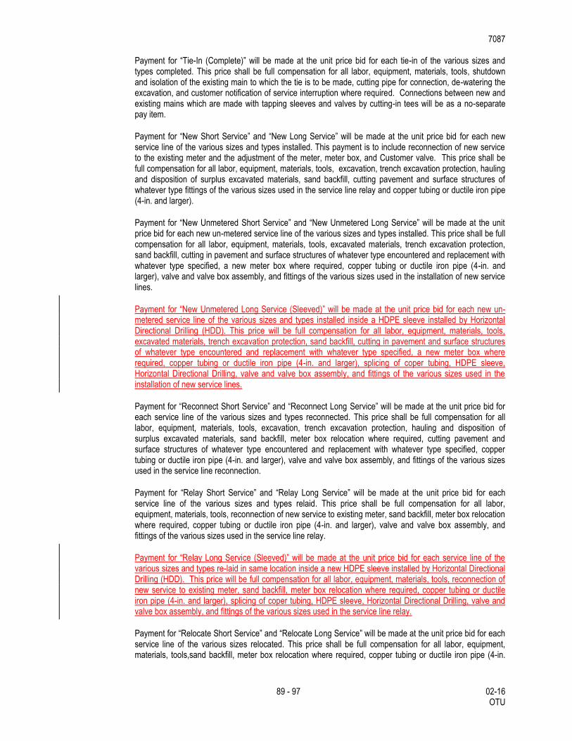
7087
89 - 97 02-16 OTU
Payment for “Tie-In (Complete)” will be made at the unit price bid for each tie-in of the various sizes and types completed. This price shall be full compensation for all labor, equipment, materials, tools, shutdown and isolation of the existing main to which the tie is to be made, cutting pipe for connection, de-watering the excavation, and customer notification of service interruption where required. Connections between new and existing mains which are made with tapping sleeves and valves by cutting-in tees will be as a no-separate pay item.
Payment for “New Short Service” and “New Long Service” will be made at the unit price bid for each new service line of the various sizes and types installed. This payment is to include reconnection of new service to the existing meter and the adjustment of the meter, meter box, and Customer valve. This price shall be full compensation for all labor, equipment, materials, tools, excavation, trench excavation protection, hauling and disposition of surplus excavated materials, sand backfill, cutting pavement and surface structures of whatever type fittings of the various sizes used in the service line relay and copper tubing or ductile iron pipe (4-in. and larger).
Payment for “New Unmetered Short Service” and “New Unmetered Long Service” will be made at the unit price bid for each new un-metered service line of the various sizes and types installed. This price shall be full compensation for all labor, equipment, materials, tools, excavated materials, trench excavation protection, sand backfill, cutting in pavement and surface structures of whatever type encountered and replacement with whatever type specified, a new meter box where required, copper tubing or ductile iron pipe (4-in. and larger), valve and valve box assembly, and fittings of the various sizes used in the installation of new service lines.
Payment for “New Unmetered Long Service (Sleeved)” will be made at the unit price bid for each new un-metered service line of the various sizes and types installed inside a HDPE sleeve installed by Horizontal Directional Drilling (HDD). This price will be full compensation for all labor, equipment, materials, tools, excavated materials, trench excavation protection, sand backfill, cutting in pavement and surface structures of whatever type encountered and replacement with whatever type specified, a new meter box where required, copper tubing or ductile iron pipe (4-in. and larger), splicing of coper tubing, HDPE sleeve, Horizontal Directional Drilling, valve and valve box assembly, and fittings of the various sizes used in the installation of new service lines.
Payment for “Reconnect Short Service” and “Reconnect Long Service” will be made at the unit price bid for each service line of the various sizes and types reconnected. This price shall be full compensation for all labor, equipment, materials, tools, excavation, trench excavation protection, hauling and disposition of surplus excavated materials, sand backfill, meter box relocation where required, cutting pavement and surface structures of whatever type encountered and replacement with whatever type specified, copper tubing or ductile iron pipe (4-in. and larger), valve and valve box assembly, and fittings of the various sizes used in the service line reconnection.
Payment for “Relay Short Service” and “Relay Long Service” will be made at the unit price bid for each service line of the various sizes and types relaid. This price shall be full compensation for all labor, equipment, materials, tools, reconnection of new service to existing meter, sand backfill, meter box relocation where required, copper tubing or ductile iron pipe (4-in. and larger), valve and valve box assembly, and fittings of the various sizes used in the service line relay.
Payment for “Relay Long Service (Sleeved)” will be made at the unit price bid for each service line of the various sizes and types re-laid in same location inside a new HDPE sleeve installed by Horizontal Directional Drilling (HDD). This price will be full compensation for all labor, equipment, materials, tools, reconnection of new service to existing meter, sand backfill, meter box relocation where required, copper tubing or ductile iron pipe (4-in. and larger), splicing of coper tubing, HDPE sleeve, Horizontal Directional Drilling, valve and valve box assembly, and fittings of the various sizes used in the service line relay.
Payment for “Relocate Short Service” and “Relocate Long Service” will be made at the unit price bid for each service line of the various sizes relocated. This price shall be full compensation for all labor, equipment, materials, tools,sand backfill, meter box relocation where required, copper tubing or ductile iron pipe (4-in.
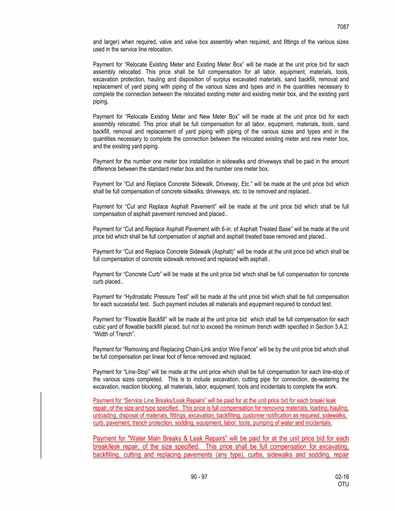
7087
90 - 97 02-16 OTU
and larger) when required, valve and valve box assembly when required, and fittings of the various sizes used in the service line relocation.
Payment for “Relocate Existing Meter and Existing Meter Box” will be made at the unit price bid for each assembly relocated. This price shall be full compensation for all labor, equipment, materials, tools, excavation protection, hauling and disposition of surplus excavated materials, sand backfill, removal and replacement of yard piping with piping of the various sizes and types and in the quantities necessary to complete the connection between the relocated existing meter and existing meter box, and the existing yard piping.
Payment for “Relocate Existing Meter and New Meter Box” will be made at the unit price bid for each assembly relocated. This price shall be full compensation for all labor, equipment, materials, tools, sand backfill, removal and replacement of yard piping with piping of the various sizes and types and in the quantities necessary to complete the connection between the relocated existing meter and new meter box, and the existing yard piping.
Payment for the number one meter box installation in sidewalks and driveways shall be paid in the amount difference between the standard meter box and the number one meter box.
Payment for “Cut and Replace Concrete Sidewalk, Driveway, Etc.” will be made at the unit price bid which shall be full compensation of concrete sidwalks, driveways, etc. to be removed and replaced..
Payment for “Cut and Replace Asphalt Pavement” will be made at the unit price bid which shall be full compensation of asphalt pavement removed and placed..
Payment for “Cut and Replace Asphalt Pavement with 6-in. of Asphalt Treated Base” will be made at the unit price bid which shall be full compensation of asphalt and asphalt treated base removed and placed..
Payment for “Cut and Replace Concrete Sidewalk (Asphalt)” will be made at the unit price bid which shall be full compensation of concrete sidewalk removed and replaced with asphalt..
Payment for “Concrete Curb” will be made at the unit price bid which shall be full compensation for concrete curb placed..
Payment for “Hydrostatic Pressure Test” will be made at the unit price bid which shall be full compensation for each successful test. Such payment includes all materials and equipment required to conduct test.
Payment for “Flowable Backfill” will be made at the unit price bid which shall be full compensation for each cubic yard of flowable backfill placed, but not to exceed the minimum trench width specified in Section 3.A.2. “Width of Trench”.
Payment for “Removing and Replacing Chain-Link and/or Wire Fence” will be by the unit price bid which shall be full compensation per linear foot of fence removed and replaced.
Payment for “Line-Stop” will be made at the unit price which shall be full compensation for each line-stop of the various sizes completed. This is to include excavation, cutting pipe for connection, de-watering the excavation, reaction blocking, all materials, labor, equipment, tools and incidentals to complete the work.
Payment for “Service Line Breaks/Leak Repairs” will be paid for at the unit price bid for each break/ leak repair, of the size and type specified. This price is full compensation for removing materials, loading, hauling, unloading, disposal of materials, fittings, excavation, backfilling, customer notification as required, sidewalks, curb, pavement, trench protection, sodding, equipment, labor, tools, pumping of water and incidentals.
Payment for "Water Main Breaks & Leak Repairs” will be paid for at the unit price bid for each break/leak repair, of the size specified. This price shall be full compensation for excavating, backfilling, cutting and replacing pavements (any type), curbs, sidewalks and sodding, repair
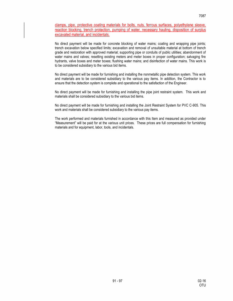
7087
91 - 97 02-16 OTU
clamps, pipe, protective coating materials for bolts, nuts, ferrous surfaces, polyethylene sleeve, reaction blocking, trench protection, pumping of water, necessary hauling, disposition of surplus excavated material, and incidentals.
No direct payment will be made for concrete blocking of water mains; coating and wrapping pipe joints; trench excavation below specified limits; excavation and removal of unsuitable material at bottom of trench grade and restoration with approved material; supporting pipe or conduits of public utilities; abandonment of water mains and valves; resetting existing meters and meter boxes in proper configuration; salvaging fire hydrants, valve boxes and meter boxes; flushing water mains; and disinfection of water mains. This work is to be considered subsidiary to the various bid items.
No direct payment will be made for furnishing and installing the nonmetallic pipe detection system. This work and materials are to be considered subsidiary to the various pay items. In addition, the Contractor is to ensure that the detection system is complete and operational to the satisfaction of the Engineer.
No direct payment will be made for furnishing and installing the pipe joint restraint system. This work and materials shall be considered subsidiary to the various bid items.
No direct payment will be made for furnishing and installing the Joint Restraint System for PVC C-905. This work and materials shall be considered subsidiary to the various pay items.
The work performed and materials furnished in accordance with this Item and measured as provided under “Measurement” will be paid for at the various unit prices. These prices are full compensation for furnishing materials and for equipment, labor, tools, and incidentals.
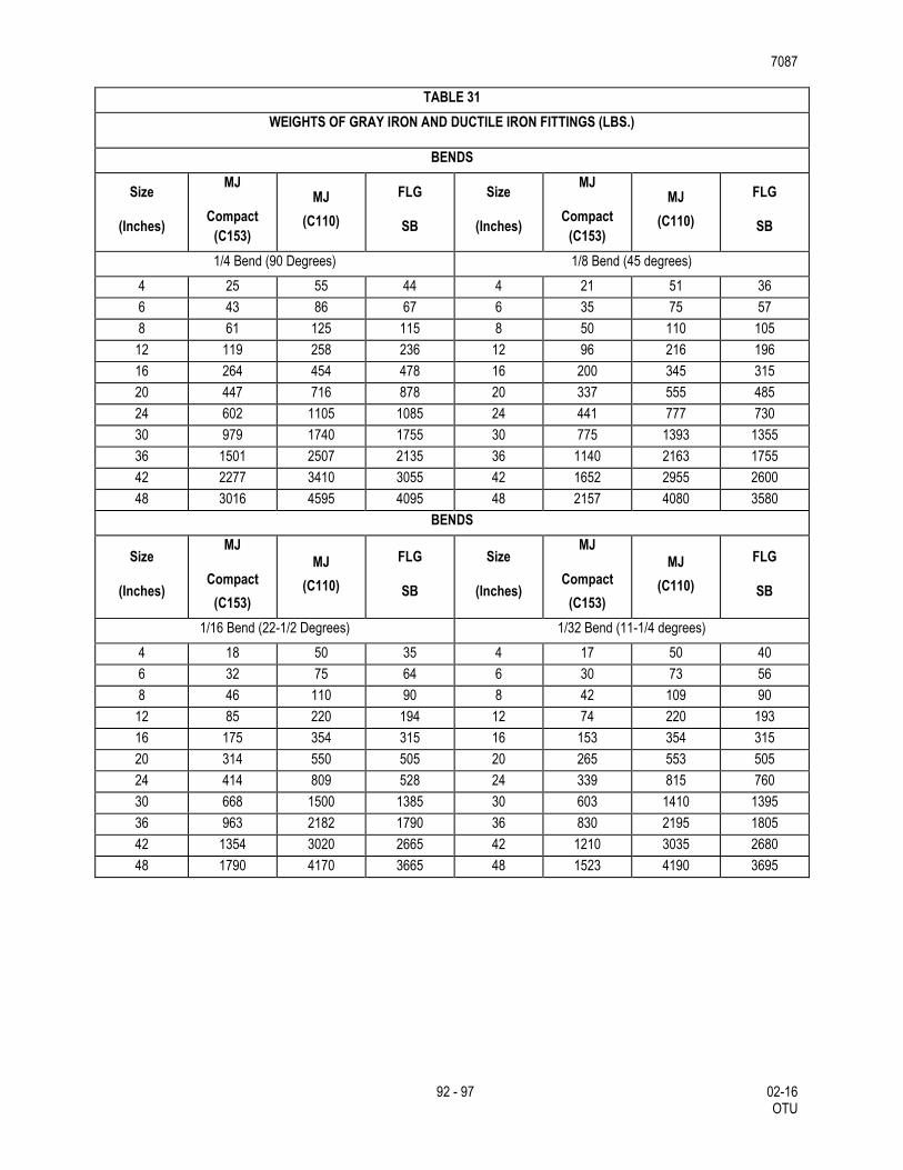
7087
92 - 97 02-16 OTU
TABLE 31
WEIGHTS OF GRAY IRON AND DUCTILE IRON FITTINGS (LBS.)
BENDS
Size
(Inches)
MJ
Compact
(C153)
MJ
(C110)
FLG
SB
Size
(Inches)
MJ
Compact
(C153)
MJ
(C110)
FLG
SB
1/4 Bend (90 Degrees) 1/8 Bend (45 degrees)
4 25 55 44 4 21 51 36
6 43 86 67 6 35 75 57
8 61 125 115 8 50 110 105
12 119 258 236 12 96 216 196
16 264 454 478 16 200 345 315
20 447 716 878 20 337 555 485
24 602 1105 1085 24 441 777 730
30 979 1740 1755 30 775 1393 1355
36 1501 2507 2135 36 1140 2163 1755
42 2277 3410 3055 42 1652 2955 2600
48 3016 4595 4095 48 2157 4080 3580
BENDS
Size
(Inches)
MJ
Compact
(C153)
MJ
(C110)
FLG
SB
Size
(Inches)
MJ
Compact
(C153)
MJ
(C110)
FLG
SB
1/16 Bend (22-1/2 Degrees) 1/32 Bend (11-1/4 degrees)
4 18 50 35 4 17 50 40
6 32 75 64 6 30 73 56
8 46 110 90 8 42 109 90
12 85 220 194 12 74 220 193
16 175 354 315 16 153 354 315
20 314 550 505 20 265 553 505
24 414 809 528 24 339 815 760
30 668 1500 1385 30 603 1410 1395
36 963 2182 1790 36 830 2195 1805
42 1354 3020 2665 42 1210 3035 2680
48 1790 4170 3665 48 1523 4190 3695
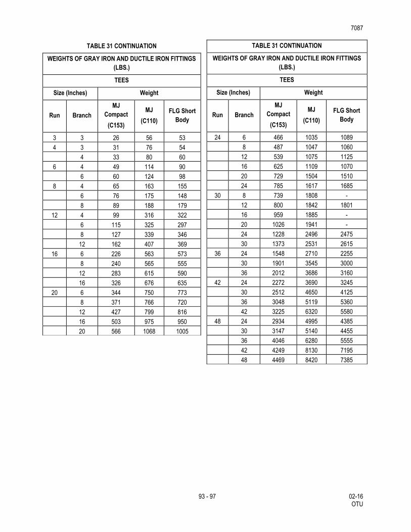
7087
93 - 97 02-16 OTU
TABLE 31 CONTINUATION
WEIGHTS OF GRAY IRON AND DUCTILE IRON FITTINGS
(LBS.)
TEES
Size (Inches) Weight
Run Branch
MJ
Compact
(C153)
MJ
(C110)
FLG Short
Body
3 3 26 56 53
4 3 31 76 54
4 33 80 60
6 4 49 114 90
6 60 124 98
8 4 65 163 155
6 76 175 148
8 89 188 179
12 4 99 316 322
6 115 325 297
8 127 339 346
12 162 407 369
16 6 226 563 573
8 240 565 555
12 283 615 590
16 326 676 635
20 6 344 750 773
8 371 766 720
12 427 799 816
16 503 975 950
20 566 1068 1005
TABLE 31 CONTINUATION
WEIGHTS OF GRAY IRON AND DUCTILE IRON FITTINGS
(LBS.)
TEES
Size (Inches) Weight
Run Branch
MJ
Compact
(C153)
MJ
(C110)
FLG Short
Body
24 6 466 1035 1089
8 487 1047 1060
12 539 1075 1125
16 625 1109 1070
20 729 1504 1510
24 785 1617 1685
30 8 739 1808 -
12 800 1842 1801
16 959 1885 -
20 1026 1941 -
24 1228 2496 2475
30 1373 2531 2615
36 24 1548 2710 2255
30 1901 3545 3000
36 2012 3686 3160
42 24 2272 3690 3245
30 2512 4650 4125
36 3048 5119 5360
42 3225 6320 5580
48 24 2934 4995 4385
30 3147 5140 4455
36 4046 6280 5555
42 4249 8130 7195
48 4469 8420 7385
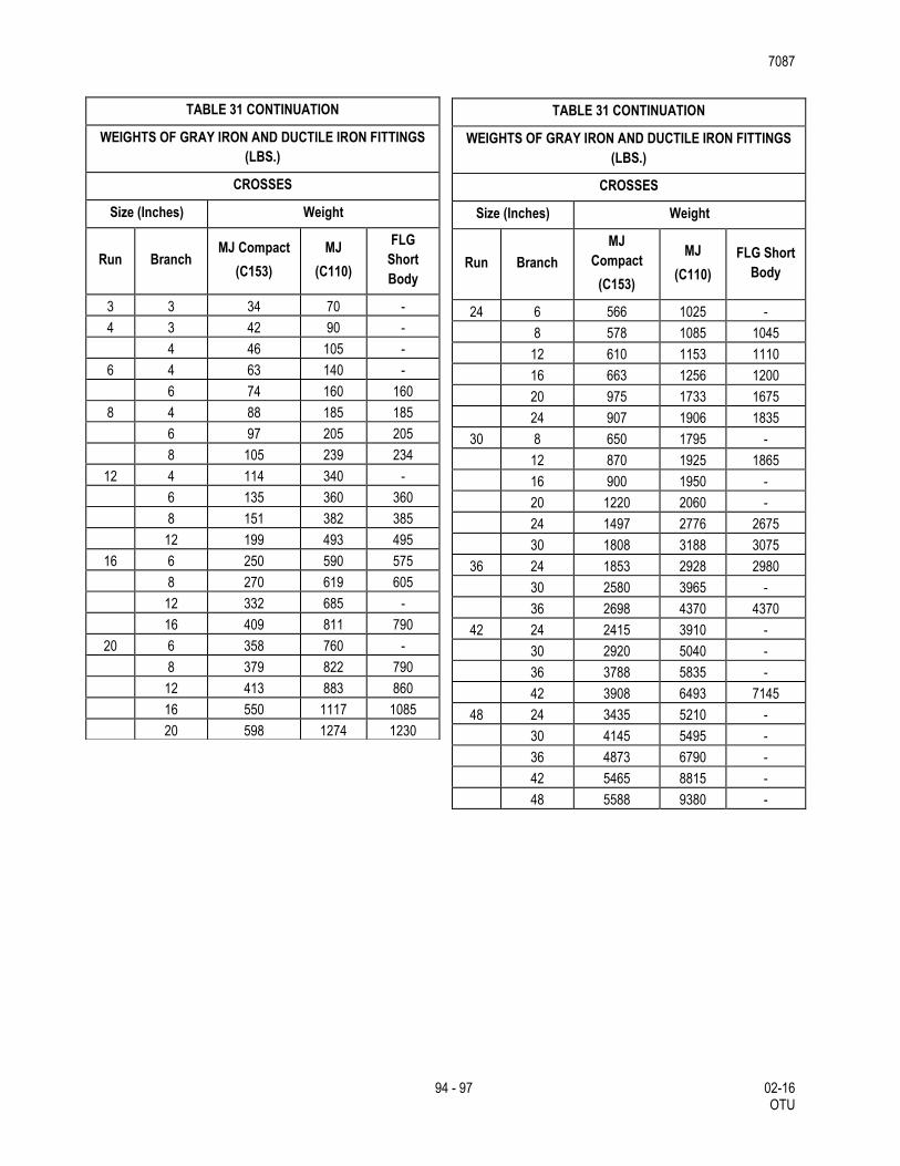
7087
94 - 97 02-16 OTU
TABLE 31 CONTINUATION
WEIGHTS OF GRAY IRON AND DUCTILE IRON FITTINGS
(LBS.)
CROSSES
Size (Inches) Weight
Run Branch MJ Compact
(C153)
MJ
(C110)
FLG
Short
Body
3 3 34 70 -
4 3 42 90 -
4 46 105 -
6 4 63 140 -
6 74 160 160
8 4 88 185 185
6 97 205 205
8 105 239 234
12 4 114 340 -
6 135 360 360
8 151 382 385
12 199 493 495
16 6 250 590 575
8 270 619 605
12 332 685 -
16 409 811 790
20 6 358 760 -
8 379 822 790
12 413 883 860
16 550 1117 1085
20 598 1274 1230
TABLE 31 CONTINUATION
WEIGHTS OF GRAY IRON AND DUCTILE IRON FITTINGS
(LBS.)
CROSSES
Size (Inches) Weight
Run Branch
MJ
Compact
(C153)
MJ
(C110)
FLG Short
Body
24 6 566 1025 -
8 578 1085 1045
12 610 1153 1110
16 663 1256 1200
20 975 1733 1675
24 907 1906 1835
30 8 650 1795 -
12 870 1925 1865
16 900 1950 -
20 1220 2060 -
24 1497 2776 2675
30 1808 3188 3075
36 24 1853 2928 2980
30 2580 3965 -
36 2698 4370 4370
42 24 2415 3910 -
30 2920 5040 -
36 3788 5835 -
42 3908 6493 7145
48 24 3435 5210 -
30 4145 5495 -
36 4873 6790 -
42 5465 8815 -
48 5588 9380 -
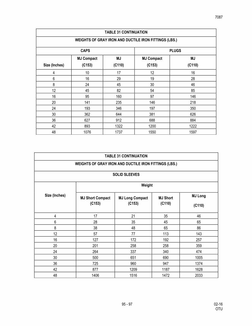
7087
95 - 97 02-16 OTU
TABLE 31 CONTINUATION
WEIGHTS OF GRAY IRON AND DUCTILE IRON FITTINGS (LBS.)
CAPS PLUGS
Size (Inches)
MJ Compact
(C153)
MJ
(C110)
MJ Compact
(C153)
MJ
(C110)
4 10 17 12 16
6 16 29 19 28
8 24 45 30 46
12 45 82 54 85
16 95 160 97 146
20 141 235 146 218
24 193 346 197 350
30 362 644 381 626
36 627 912 688 884
42 893 1322 1200 1222
48 1076 1737 1550 1597
TABLE 31 CONTINUATION
WEIGHTS OF GRAY IRON AND DUCTILE IRON FITTINGS (LBS.)
SOLID SLEEVES
Size (Inches)
Weight
MJ Short Compact
(C153)
MJ Long Compact
(C153)
MJ Short
(C110)
MJ Long
(C110)
4 17 21 35 46
6 28 35 45 65
8 38 48 65 86
12 57 77 113 143
16 127 172 192 257
20 201 258 258 359
24 264 337 340 474
30 500 651 690 1005
36 725 960 947 1374
42 877 1209 1187 1628
48 1406 1516 1472 2033
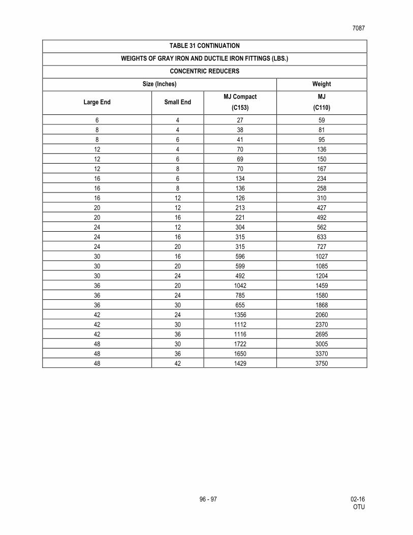
7087
96 - 97 02-16 OTU
TABLE 31 CONTINUATION
WEIGHTS OF GRAY IRON AND DUCTILE IRON FITTINGS (LBS.)
CONCENTRIC REDUCERS
Size (Inches) Weight
Large End Small End MJ Compact
(C153)
MJ
(C110)
6 4 27 59
8 4 38 81
8 6 41 95
12 4 70 136
12 6 69 150
12 8 70 167
16 6 134 234
16 8 136 258
16 12 126 310
20 12 213 427
20 16 221 492
24 12 304 562
24 16 315 633
24 20 315 727
30 16 596 1027
30 20 599 1085
30 24 492 1204
36 20 1042 1459
36 24 785 1580
36 30 655 1868
42 24 1356 2060
42 30 1112 2370
42 36 1116 2695
48 30 1722 3005
48 36 1650 3370
48 42 1429 3750
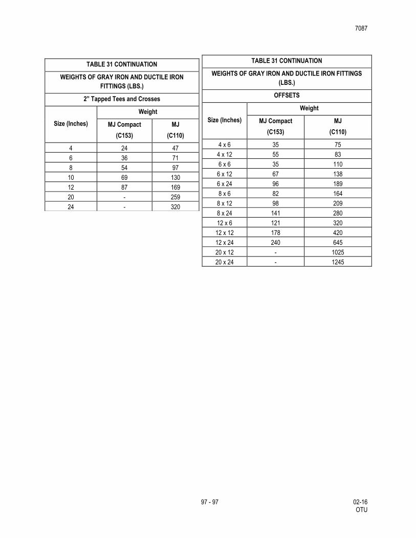
7087
97 - 97 02-16 OTU
TABLE 31 CONTINUATION
WEIGHTS OF GRAY IRON AND DUCTILE IRON
FITTINGS (LBS.)
2” Tapped Tees and Crosses
Size (Inches)
Weight
MJ Compact
(C153)
MJ
(C110)
4 24 47
6 36 71
8 54 97
10 69 130
12 87 169
20 - 259
24 - 320
TABLE 31 CONTINUATION
WEIGHTS OF GRAY IRON AND DUCTILE IRON FITTINGS
(LBS.)
OFFSETS
Size (Inches)
Weight
MJ Compact
(C153)
MJ
(C110)
4 x 6 35 75
4 x 12 55 83
6 x 6 35 110
6 x 12 67 138
6 x 24 96 189
8 x 6 82 164
8 x 12 98 209
8 x 24 141 280
12 x 6 121 320
12 x 12 178 420
12 x 24 240 645
20 x 12 - 1025
20 x 24 - 1245