speaker - indian institute of technology madras · 2016-09-06 · photoelectrons and directly probe...
TRANSCRIPT

Speaker: Sudhakar

Introduction Currently, AP-XPS is utilized in many important research fields such as heterogeneous catalysis, fuel
cell, batteries, and environmental science.
Some of the most important physical and chemical processes in nature, particularly in electrochemistry, take place at interfaces between solid-liquid phases.
Photon energies used for XPS, either by using laboratory based or synchrotron radiation sources, typically are less than 2000 eV.
Photoelectrons (PEs) generated by these soft X-ray sources have limited inelastic mean free path of only a few Angstrom (<20 Å) in solid materials. thus conventional XPS is inherently a surface sensitive characterization technique.
Conventional XPS measurements: they require ultra-high vacuum (UHV) conditions to avoid the electron scattering with gas molecules as well as the surface contaminations.
To study solid-liquid interface using AP-XPS, they have constructed a new AP-XPS system equipped with a Scienta HiPP-2electron analyzer and a three-electrode in situ electrochemistry apparatus.

Outline of this paper
“Tender” X-ray AP-XPS system
Analyzer performance
Thin film and it’s thickness
Electrochemical cell
“Dip & pull” methodSystem design and principle

The IMFP and photo-ionization cross-section are universally dependent upon electron kinetic energy and photon energy respectively for all core levels
1. Integrated area of Fe 2p for a 1 nm Fe interface layer as a function of photon energy buried under various thicknesses of carbon to illustrate the ideal photon energy region for studying interface phenomena in systems on the order of 10’s of nm in thickness.
2. The inset is a representation of the electrolyte, electrode, and electrolyte-electrode interface layer used in the SESSA simulation used to generate the data for this plot.
3. Based on this model “tender” X-ray photons with energies between 2-7 keV offer the best signal to noise ratio
“Tender” X-ray AP-XPS system and design principle

a) Schematic top view of the “tender” X-ray AP-XPS analyzer and analysis chamber.b) Detailed representation of the analysis chamber.c) Photo of the actual “tender” X-ray AP-XPS analyzer and the analysis chamber that is directly
connected to the analyzer.

(a) Au 4f spectra of Au foil in Ar gas at different pressures.
(b) integrated intensity of the Au 4f spectra relative to the vacuum condition as a function of Ar pressure.
(c) Au 4f of Au foil in Ar gas at pressure ranges from 50 Torr to 110 Torr using a 0.1 mm diameter aperture cone.
Performance of “tender” X-ray AP-XPS endstation


Verification of the thin electrolyte film thickness
The Pt 4f intensity of WE, escaping through an over-layer of thin electrolyte film is IEC.
Ip is the Pt intensity from the electrode exposed to water vapor only.
Electron escape depth is λe, θ is the angle between the escaping electron with the sample surface normal.
After several similar “dip & pull” experiments are performed, The electrolyte thickness on Pt WE is found to be in the range of 10 to 30 nm.
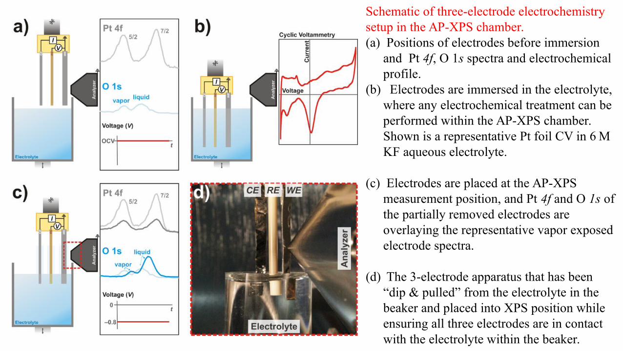
Schematic of three-electrode electrochemistry setup in the AP-XPS chamber. (a) Positions of electrodes before immersion
and Pt 4f, O 1s spectra and electrochemical profile.
(b) Electrodes are immersed in the electrolyte, where any electrochemical treatment can be performed within the AP-XPS chamber. Shown is a representative Pt foil CV in 6 M KF aqueous electrolyte.
(c) Electrodes are placed at the AP-XPS measurement position, and Pt 4f and O 1s of the partially removed electrodes are overlaying the representative vapor exposed electrode spectra.
(d) The 3-electrode apparatus that has been “dip & pulled” from the electrolyte in the beaker and placed into XPS position while ensuring all three electrodes are in contact with the electrolyte within the beaker.

(a) Pt 4f of clean Pt foil in 1 × 10 −3 Torr (grey), under 20 Torr of water vapor pressure (light blue), and under 0.8 V potential with CV treatment (dark blue).
(b) Integrated intensity of the Pt 4f spectra relative to the UHV condition at different treatment conditions.
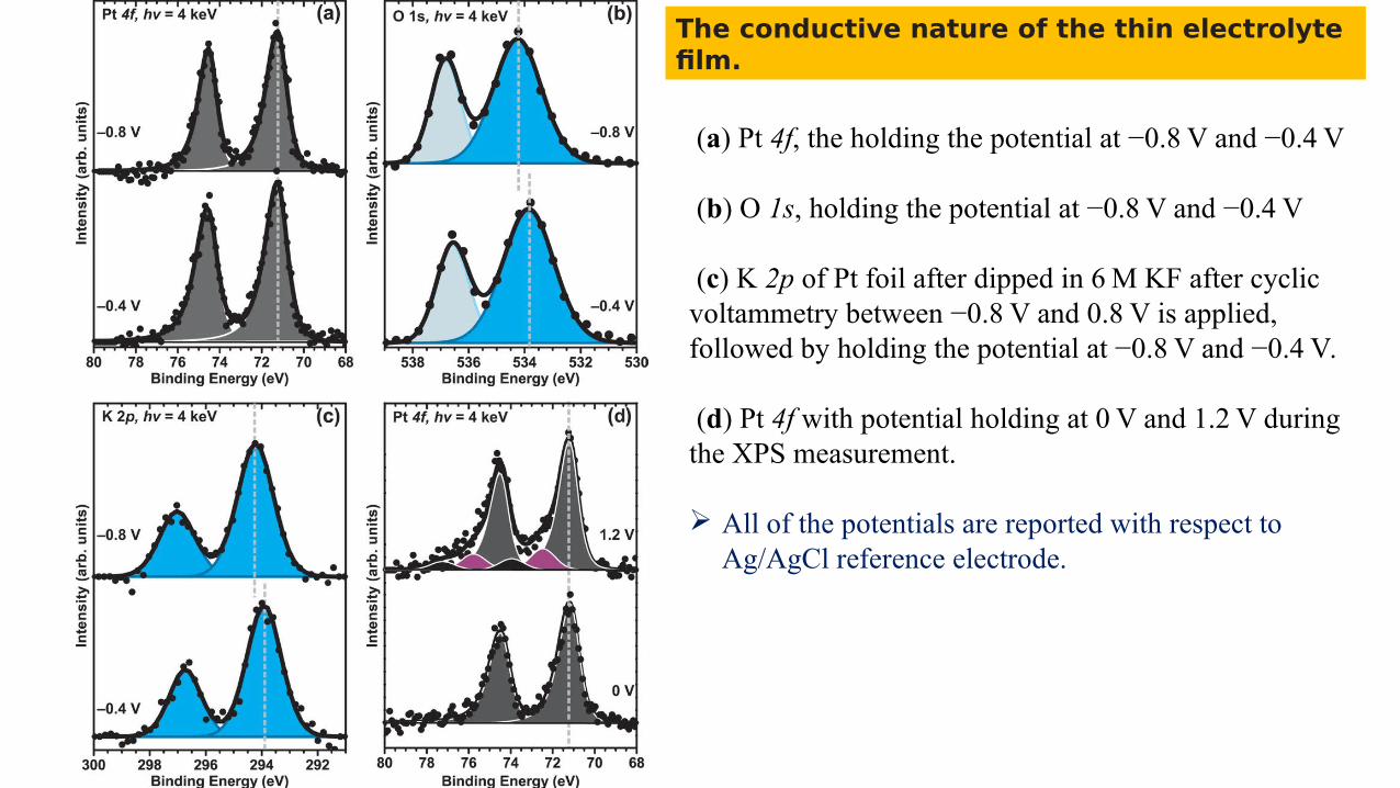
(a) Pt 4f, the holding the potential at −0.8 V and −0.4 V
(b) O 1s, holding the potential at −0.8 V and −0.4 V
(c) K 2p of Pt foil after dipped in 6 M KF after cyclic voltammetry between −0.8 V and 0.8 V is applied, followed by holding the potential at −0.8 V and −0.4 V.
(d) Pt 4f with potential holding at 0 V and 1.2 V during the XPS measurement.
All of the potentials are reported with respect to Ag/AgCl reference electrode.
The conductive nature of the thin electrolyte film.

Summary
1. They observed the formation of both Pt2+ and Pt4+ interfacial species on the Pt working electrode in situ.
2. They were able to access the interface between liquid and solid dense phases with photoelectrons and directly probe important phenomena occurring at the narrow solid-liquid interface region in an electrochemical system.
3. They can able to find out electrolyte layer thickness and it is conductive or nonconductive.
Future plan
1. To get most of Cluster information in realistic conditions.
2. Adsorption of ions on metal oxide surface.

Silly application If we apply photo electron effect to solar system
If Comet have more energy than Binding energy of Mercury , If Mercury removed from solar system.What will happen to earth?
TThank you for kind attention