Äspö hard rock laboratory · box 5864 se-102 40 stockholm sweden ... canister, rock, earth quake,...
TRANSCRIPT
Svensk Kärnbränslehantering ABSwedish Nuclear Fueland Waste Management CoBox 5864SE-102 40 Stockholm SwedenTel 08-459 84 00
+46 8 459 84 00Fax 08-661 57 19
+46 8 661 57 19
InternationalProgress Report
IPR-06-13
Äspö Hard Rock Laboratory
ROSE, ROck Shear Experiment
A feasibility study
Lennart Börgesson
Torbjörn Sandén
Lars-Erik Johannesson
Clay Technology AB
Håkan Knutsson
Fenix Engineering AB
December 2004

Report no. No.
IPR-06-13 F126KAuthor Date
Lennart Börgesson December 2004Torbjörn SandénLars-Erik JohannessonHåkan KnutssonChecked by Date
Lennart Börgesson 2006-08-16Approved Date
Anders Sjöland 2006-08-16
Keywords: Buffer, Bentonite, Canister, Rock, Earth quake, Modelling, Field test,Feasibility
This report concerns a study which was conducted for SKB. The conclusionsand viewpoints presented in the report are those of the author(s) and do notnecessarily coincide with those of the client.
Äspö Hard Rock Laboratory
ROSE, ROck Shear Experiment
A feasibility study
Lennart Börgesson
Torbjörn Sandén
Lars-Erik Johannesson
Clay Technology AB
Håkan Knutsson
Fenix Engineering AB
December 2004
1
Summary
Rock shear is one of the few processes that seriously can damage the canister. It is also a process that is easy to understand and that obviously is a threat against the integrity of the waste and by that important to demonstrate.
Fractures and fracture systems are natural components in granitic rock and can not be completely avoided in the repository areas. Displacement along such fractures caused by seismic events may intersect deposition holes and thus affect the canister. The buffer in KBS-3 is assumed to protect the canister from loosing its integrity for instant displacements up to 100 mm. The stresses in the canister and the buffer at such a major displacement have been modelled as well as analysed based on experiments in laboratory scale (small up to 1:10 scale). The results need, however, to be verified in larger scale than 1:10, if a significantly more accurate criterion shall be feasible to apply in the accepting/rejecting process.
The ROSE project aims at observing the stresses and strains in a KBS-3 canister if a displacement of 100 mm would take place in a horizontal fracture that crosses a deposition hole at canister height. Such a displacement is considered to be caused by an earthquake, and the test set-up will provide a shearing motion along the fracture that is equal to an expected shearing motion in real life. The ultimate aim is to demonstrate that the effect of a rock shear can be predicted and that it is not detrimental for the canister.
The test set-up is planned to use the site of the Äspö Pillar Stability Experiment when the rock mechanics test there has been completed. Two full scale deposition holes then exist with a rock pillar of 1 m in between. The figure below illustrates the present, schematic idea for a test set-up. The left deposition hole will be used for the buffer and canister, while the right deposition hole will be used for the shearing equipment. Half of the rock between the holes will be removed (is partly fractured after the Apse test) and replaced by a steel construction that can move horizontally along a shear planbe in an artificial fracture. Part of the left hand hole is enlarged by sawing away about 200 mm in order to make room for the shear displacement. This upper part, which shall be sheared, is surrounded by a steel cylinder, which is attached to the steel structure and is mobile in the direction of the shear. The hole will be plugged by a steel plug, which is anchored to the rock by rock anchors as in Canister Retrieval Test and Temperature Buffer Test. The fast shearing will be generated by highly pressurized nitrogen that drives hydraulic flow to 6 pressure cylinders.
The shearing should not be done before the buffer has been saturated, but this time can be reached after about two years by using highly saturated bentonite blocks with 95–98 % saturation and by lining the hole with permeable mats for artificial water supply. The planned shear speed is 0.1 m/s.

2
The feasibility study has included the following items:
• Localization of a suitable place for the test
• Modelling of the saturation phase and the shear phase for design purpose and for evaluation of expected results
• Design of the buffer material and the water saturation system in order to reach sufficient maturation of the buffer within about 2 years
• Design of the test set-up for fulfilling the requirements of the test
• Design of the shearing equipment and the pneumatic system for producing a constant rate of deformation of 0.1 m/second
• Relevant time schedule
The conclusion from the study is that the test can be accomplished with the desired demands for simulating the effect of a critical rock shear. The modelling shows that the maturation can be fulfilled in about 2 years if wetting is supplied from filter mats surrounding the buffer. The modelling also shows that the effect of the rock shear is not detrimental for the canister.
R4
C1
R1
R3
R2
R9
R5
R6
R7
R8
R10
C2Sliding plane
Shear plane
Shearing cylinder
Rear press beamFront press beamHydraulic cylinders
Steel flange
Supporting plug
Bentonite blocks
Copper canister
Illustration of the set-up of ROSE

3
Sammanfattning
Bergskjuvning är en av de få processer som allvarligt kan skada kapseln. Det är också en process som är lätt att förstå och som uppenbarligen är ett hot mot avfallets integritet och det är således viktig att visa att den inte skadar kapseln allvarligt.
Sprickor och spricksystem är naturliga beståndsdelar hos granitiskt berg och kan inte undvikas i förvarsområdet. Förskjutningar längs sådana sprickor som orsakats av seismiska händelser kan genomskära deponeringsshålet och på så sätt påverka kapseln. Bufferten i ett KBS-3 antas skydda kapseln från att förlora sin integritet vid förskjutningar på upp till 100 mm. Spänningen i kapseln och bufferten vid sådana större förskjutningar har såväl modellerats som analyserats med hjälp av experiment i laboratorieskala (upp till skalan 1:10). Resultaten behöver dock bekräftas i större skala än 1:10 för accepterande/avvisande-processen.
Syftet med ROSE-projektet är att observera spänningar och påfrestningar i en KBS-3-kapsel om ett förskjutning på 100 mm skulle äga rum i en horisontell spricka som skär genom ett förvarshål i kanisterhöjd. En sådan förskjutning antas vara förorsakad av en jordbävning, och försöksuppställningen kommer att innefatta en skjuvrörelse längs sprickan som motsvarar en förväntad verklig skjuvrörelse. Det slutliga syftet är att visa att effekten av bergskjuvning kan förutsägas och att den inte är skadlig för kapseln.
Försöksuppställningen avses förläggas på platsen för Äspö Pillar Stability Experiment när bergmekanikförsöket där har avslutats. Där finns två deponeringshål i full skala med en enmeters bergspelare mellan hållen. Figuren nedan visar den nuvarande schematiska idén till en försöksuppställning. Det vänstra deponeringshålet kommer att användas för bufferten och kapseln, medan det högra hålet kommer att användas för skjuvningsutrustningen. Minst älften av berget mellan hålen kommer att avlägnas och ersättas med en stålkonstruktion som kan flyttas horisontellt längs ett skjuvplan i en artificiell spricka. En del av det vänstra hålet förstoras genom att man sågar bort ca 20 mm för att göra plats för skjuvrörelsen. Denna övre del som ska skjuvas omges av en stålcylinder som är fäst vid stålkonstruktionen, och som är rörlig i skjuvningsriktningen. Hålet kommer att förseglas med en stålplugg som färsts vid berget med bergankare som i Canister Retrieval Test och i Temperature Buffer Test. Den snabba skjuvningen kommer att genereras av kvävgas med högt tryck som alstrar ett hydrauliskt flöde till 6 tryckcylindrar.
Skjuvningen får inte ske förrän bufferten har vattenmättats och homogenisertas, men detta kan uppnås efter ca 2 år genom att använda bentonitblock med en mättnadsgrad på 95-98% och genom att klä hålet med en permeabel matta för konstgjord vattentillförsel. Den planerade skjuvningshastigheten är 0.1 m/s.

4
Studien har innefattat följande punkter:
• Lokalisering av lämplig plats för försöket
• Modellering av mättnadsfasen och skjuvningsfasen för designändamål och för utvärdering av förväntade resultat
• Design av buffertmaterial och vattenmättnadssystem för att uppnå tllräcklig mognad hos bufferten inom ca 2 år
• Design av försöksuppställning för att uppfylla försökskraven
• Design av skjuvningsutrustning och tryckluftsssystem för att skapa en konstant deformationshastighet på 0.1 m/sekund
• Relevant tidsplan
Slutsatserna från studien är att försöket kan utföras med de önskade kraven för att simulera effekterna av en kritisk bergsskjuvning. Modelleringen visar att mognad kan uppnås på ca 2 år om bevätning tillgodoses genom filtermattor runt bufferten. Modelleringen visar också att effekten av bergsskjuvning inte är skadlig för kapseln.
R4
C1
R1
R3
R2
R9
R5
R6
R7
R8
R10
C2Sliding plane
Shear plane
Shearing cylinder
Rear press beamFront press beamHydraulic cylinders
Steel flange
Supporting plug
Bentonite blocks
Copper canister
Illustration av föreslagen försöksuppställning för ROSE

5
Contents
Summary 1
Sammanfattning 3
1 Background and purpose 6
2 Suggested design and components 7 2.1 General 7 2.2 Layout 9 2.3 Experimental site 10 2.4 Buffer material 11 2.5 Canister 14 2.6 Hydraulic press 14
2.6.1 General 14 2.6.2 Rear press beam 14 2.6.3 Front press beam 15 2.6.4 Press guides 15 2.6.5 Hydraulic system and Control system 16
2.7 Shearing cylinder 17 2.7.1 General 17 2.7.2 Shear plane 17 2.7.3 Sliding plane 18 2.7.4 Upper supporting plug 18
2.8 Instrumentation 20
3 Test procedure 24
4 Predicted outcome 26 4.1 General 26 4.2 Maturation phase 26
4.2.1 Material model 26 4.2.2 Finite element model 28 4.2.3 Calculations 28
4.3 Shear phase 34 4.3.1 General 34 4.3.2 Finite element mesh 34 4.3.3 Material models 36 4.3.4 Calculation 38 4.3.5 Results 38 4.3.6 Conclusions 39
5 Evaluation and conclusions 44
References 45
Appendices 45
6
1 Background and purpose
Rock shear is one of the few processes that seriously can damage the canister. It is also a process that is easy to understand and that obviously is a threat against the integrity of the waste and by that important to demonstrate.
The effect of a rock shear has been investigated and reported at different occasions. At the latest investigation laboratory tests were done at which bentonite samples with different density were sheared at different shear velocities up to 6 m/s. The results were used for establishing a material model. In this investigation finite element calculations were performed to model a horizontal 0.2 m long shear intersecting a deposition hole. In these calculations the magnitude of the shear displacement, the shear velocity and the buffer density were varied. The results are reported in an SKB Technical Report /1-1/ and in an article presented at the latest MRS-meeting /1-2/.
The calculations show that the influence of the buffer density and the level of the shear plane are important but also that the shearing velocity and the magnitude of the shearing have a significant influence. At the two lower densities (1950 and 2000 kg/m3) an eccentric shear plane is more dangerous but at the two higher densities (2050 and 2100 kg/m3) a centric shearing is the worst case. At the conservative combination of a shearing rate of 1 m/s, a rock displacement of 20 cm and a density of 2100 kg/cm3, the iron insert will be strongly influenced, having plastic strains up to 19%, but for the reference case with a buffer density of 2000 and a rock displacement of 10 cm, the plastic strain will be reduced to 1.6%. Accordingly there is a strong theoretically basis for analysis and a prediction of a full scale test can be done with high reliability.
A full scale test for simulating such a scenario is complicated and rather different from other tests performed in Äspö HRL:
• The saturation phase and the shear phase have completely different time scales and require different measuring techniques.
• The fast shearing requires a complicated regulation system for controlling the shear rate
• A very large force (2000 tons) must be applied in a very short time
• Part of the deposition hole must be artificial in order to both withstand the swelling pressure and make the shear movement possible
• There is only one chance for shearing, which means that everything must work from start
• The buffer must be completely water saturated and matured before shearing can take place, which means that bentonite blocks with a high degree of water saturation must be made (same as for LASGIT)
In order to investigate the possibility to perform the test and pinpoint any special problems the present feasibility study was initiated. It includes suggested design, predictions of the outcome and a cost estimate.
7
2 Suggested design and components
2.1 General After termination of the “Äspö Pillar Stability Experiment”, which has been running in the TASQ tunnel at Äspö, there will be two deposition holes available. The holes have the full diameter of 1.75 m and are located with the individual distance of 1 meter at the closest points, which yields the required space for the planned experiment.
Figure 2-1 shows a schematic drawing of the planned experiment. This layout corresponds to alternative 1. There is also another alternative with the shear plane located in level with the floor that will be presented in chapter 2.2. For layout 1 the left hole will be used for the buffer and the canister while the right hole will contain the hydraulic shear equipment. Calculations show that the worst case for the reference density is shear in the quarter point of the canister. In order to make it possible to place the shear plane there, parts of the rock between the two holes have to be excavated. The upper part of the left hole must also be enlarged in order to give free space for the shear movement.
Before installing the buffer and the canister in the left hole, a steel tube surrounding the upper part of the bentonite buffer, will be placed in the hole. The tube simulates the upper part of the borehole and will be moveable in the shear direction. The movement will be controlled by special guides fixed to the rock wall. When the buffer and the canister are positioned, a steel lid will be bolted on the top of the steel tube. A steel plug will be placed on top of this lid and be held in position with 12 rock anchors (similar technique as used in CRT, TBT and in the LASGIT projects). The setup will contain one shear plane, which will be at the bottom of the shearing tube, interfacing with a short preinstalled heavy flange fixed to the rock and one sliding plane on the top between the steel lid and the plug. In order to minimize the friction during the shearing operation, the rock anchors will be adjusted just before test start so that a small slot appears at the shear plane. On the upper sliding plane a hydraulic pressure will be applied, which will decrease the friction to a minimum.

8
R4
C1
R1
R3
R2
R9
R5
R6
R7
R8
R10
C2Sliding plane
Shear plane
Shearing cylinder
Rear press beamFront press beamHydraulic cylinders
Steel flange
Supporting plug
Bentonite blocks
Copper canister
Figure 2-1. Layout of alternative 1 of the suggested test. The picture shows a vertical section through the middle of the deposition holes. The deposition hole with the bentonite blocks and the canister is located to the left while the equipment for forcing the fast shear displacement is located in the upper part of the right hole.
In order to perform a relevant experiment, the buffer has to be saturated and matured with fully developed swelling pressure and homogenized buffer before the shearing takes place. Using the standard KBS3 bentonite blocks this could take tenths of years depending on the access to water from the rock. In order to speed up the water saturation process, bentonite blocks with a high degree of saturation will be produced. In combination with a system for artificial water supply, with filter mats on the rock walls and pumps for applying a water pressure, the time for saturation and maturation can be reduced to about two years. The same principle will be used in the LASGIT experiment. The bentonite blocks for the LASGIT experiment are already manufactured which means that the technique for producing these special blocks is already tested.
Consequently the installation of the buffer and the canister must take place about two years before the installation of the hydraulic press need to be done. The main part of the rock work i.e. excavation, installation of guides on the rock wall etc. must of course be done in advance.

9
2.2 Layout Two alternative layouts for the press equipment are presented; see Figures 2-2 and 2-3. The press equipment is in principal the same for the two proposals. Both alternatives also have a shearing cylinder covering the upper two meters of the deposition hole to replace the drilled hole in the rock. The lower horizontal end of the shearing cylinder forms the shear plane. This means that the shear plane intersects the copper canister in the upper quarter point.
In alternative 1, shown in Figure 2-2, the shear plane is located about 2 meters below tunnel floor level. The press rear beam is placed in the right borehole and supported by the rear of the hole. The rock pillar between the two holes has to be excavated down to ca 2 meters.
In alterative 2, shown in Figure 2-3, the shear plane is located just below the tunnel floor. The shear direction in this alternative is perpendicular to the tunnel direction and the press placed mainly above floor level between the hole and the tunnel wall. The press is supported by the tunnel wall. Almost 1/3 of the deposition hole is thus located in the drift above the floor. Another major difference between this solution and alternative 1 is that the lid of the shearing cylinder is not supported by rock anchors but by a pillar against the roof.
Figure 2-2. View of test layout 1 with half the set-up stripped. The shear plane is located about 2 m below the tunnel floor level. The shearing cylinder surrounding the upper two meters of the deposition hole is painted dark blue. The hydraulic press consists of a rear press beam (green), a front press beam (yellow) and 6 hydraulic cylinders (light blue).

10
Figure 2-3. View of test layout 2 with half the hole on the passive side stripped. The shear plane is located at about the same level as the tunnel floor. The bentonite blocks and the canister are seen in the front and the pressure equipment for the fast shear displacement is located behind. The black lid of the shearing cylinder (dark blue) is supported against the rock roof with a special support (pillar) painted grey in the figure.
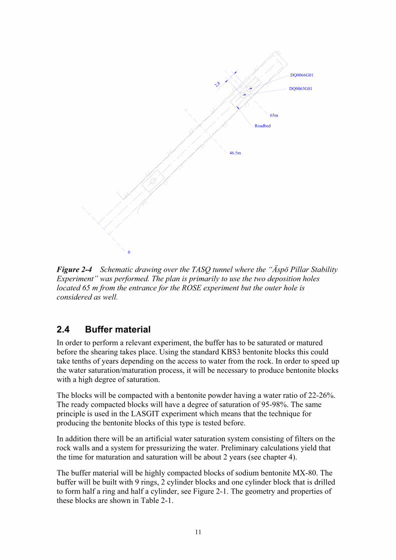
2.3 Experimental site The idea of alternative 1 is to use the two deposition holes in the TASQ tunnel. After termination of the “Äspö Pillar Stability Experiment” the two deposition holes will be available. The holes are separated by 1 meter rock, which is suitable for the space needed for the experiment. The TASQ tunnel with the two holes and the additional hole that was drilled at the same time is shown in Figure 2-4. The rock around the two inner deposition holes is rather perforated due to different bore hole tests and excavations. An alternative is to use the outer bore hole in the same tunnel with the set-up shown in Figure 2-3 (alternative 2). The bore hole is intact, which is an advantage. Both options have been considered in this study.
11
DQ0063G01
DQ0066G01
2,8
0
46.5m
65m
Roadbed
Figure 2-4 Schematic drawing over the TASQ tunnel where the “Äspö Pillar Stability Experiment” was performed. The plan is primarily to use the two deposition holes located 65 m from the entrance for the ROSE experiment but the outer hole is considered as well.
2.4 Buffer material In order to perform a relevant experiment, the buffer has to be saturated or matured before the shearing takes place. Using the standard KBS3 bentonite blocks this could take tenths of years depending on the access to water from the rock. In order to speed up the water saturation/maturation process, it will be necessary to produce bentonite blocks with a high degree of saturation.
The blocks will be compacted with a bentonite powder having a water ratio of 22-26%. The ready compacted blocks will have a degree of saturation of 95-98%. The same principle is used in the LASGIT experiment which means that the technique for producing the bentonite blocks of this type is tested before.
In addition there will be an artificial water saturation system consisting of filters on the rock walls and a system for pressurizing the water. Preliminary calculations yield that the time for maturation and saturation will be about 2 years (see chapter 4).
The buffer material will be highly compacted blocks of sodium bentonite MX-80. The buffer will be built with 9 rings, 2 cylinder blocks and one cylinder block that is drilled to form half a ring and half a cylinder, see Figure 2-1. The geometry and properties of these blocks are shown in Table 2-1.

12
Table 2-1. Bentonite blocks for the buffer
Number and type
Inner diam.
Outer diam.
Height Void ratio / dry density
Water ratio
Degree of satu-ration
Density after swelling and sat. 1)
2 full cylinders
- 1.65 m 0.5 m 0.72 / 1620 kg/m3
25.4% 98% 1990 kg/m3
9 ring 1.07 m 1.65 m 0.5 m 0.65 / 1685 kg/m3
22.2% 95% 1975 kg/m3
1 drilled cylinder
1.07 m half cyl.
1.65 m 0.5 m 0.72 / 1620 kg/m3
25.4% 98% 1971 kg/m3
1) with pellets in the 5 cm slot
The 5 cm slot between the bentonite blocks and the rock surface will be filled with pellets compacted at the water ratio 17%. The bulk density of the pellets will according to experience from other tests be 1200-1300 kg/m3. After completed installation the slot with pellets will be filled with water yielding an initial degree of saturation of the pellets filled slot of 90-95%.
The bentonite and water for the buffer blocks will be mixed with an Eirich mixer and stored in big-bags (1 ton) at Hackman-Rörstrands in Lidköping. The compaction to rings and full cylinders will be made at Hydroweld in Ystad with equipment developed and tested for the LASGIT project and other Äspö projects. After compaction the blocks will be stored in air-tight boxes, which also have been used for earlier projects.
Figure 2-5 shows a picture of the Eirich mixer at Rörstrands. Figures 2-6 and 2-7 show pictures taken during compaction and checking of a bentonite block /2-1/.
Figure 2-5. The Eirich mixer used for mixing the bentonite and water.

13
Figure 2-6. Compaction of a bentonite block at Hydroweld in Ystad.
Figure 2-7. A bentonite ring after completed compaction and dismounting.

14
2.5 Canister The canister will be obtained from the Encapsulation Project undertaken by SKB. The canister will be of BWR type. No heaters will be installed in the canister since influence of increased temperature is considered to be very small and the probability is higher that a rock shear takes place after the high temperature period than during it. The top lid of the copper canister is planned to be welded to the copper tube in order to have the most realistic design of the canister. This is in contrast to all other full scale tests at Äspö, which have the top lid bolted to the copper tube in order to facilitate the installation of heaters and sensors inside the canister. The bottom of the “ROSE-canister” should however be bolted on the same reason and cables and tubes from the inside of the canister will be led out this way. The instrumentation of the canister requires special machining of the canister (for mainly total pressure sensors and strain gauges).
2.6 Hydraulic press 2.6.1 General The design of the press and shearing cylinder is based on results from the modelling presented in chapter 4. The press is hydraulic with a press force of 23 750 kN (2 375 tons). The main parts of the press are the front and rear beams, 6 hydraulic cylinders in a 3 x 2 pattern and guidings (see Figures 2-1, 2-2 and 2-3). To get a horizontal move, the beams are vertical. The surrounding rock structure is used as press frame. To meet the asymmetry of the load caused by the difference in stiffness of the canister and the buffer, the press force centre is placed ca 125 mm lower than the centre of the shear cylinder (front beam centre). The press is powered by a set of high pressure nitrogen bottles, which generate a hydraulic pressurized flow via two or three media converters, see Figure 2-9 and Appendix 3.
Maximum hydraulic cylinder stroke:
200 mm; 100 mm for the shear stroke and 50 mm respectively for acceleration and retardation, margins for press safety included.
Press speed Forward stroke: 100 mm/sec Return stroke: 1 mm/sec
Overall dimensions of the hydraulic press:
Length: 2850 mm Width: 2100 mm Height: 2050 mm
2.6.2 Rear press beam Both press beams are made of steel and welded. The rear press beam (green in Figures 2-2 and 2-3) is mounted onto a mounting plate, anchored and cast to the rock. The six hydraulic cylinders (light blue) are mounted to the rear beam and the hydraulic pipes are placed inside the beam.

15
2.6.3 Front press beam The front press beam (yellow and grey in Figures 2-2 and 2-3) is split into two parts, the main front beam (yellow) and two spacer beams (grey). These can be separated from each other. The two spacers (grey) are mounted between the cylinder pistons and the front beam. They are 240 mm high, one for each cylinder line and may be removed to allow test runs and trimming of the press, the hydraulic and the control systems prior to the final test.
The main front beam (yellow) is shaped to fit the shear cylinder surface.
2.6.4 Press guides The front beam is mechanically guided by four guides, two on each side of the shearing cylinder. For the first lay out alternative, where the press is mounted below the floor level, the guides are mounted onto mounting plates, cast and anchored to the rock, as shown in Figure 2-8.
If the press is placed on the tunnel floor (see Figure 2-3) the guides (grey) are mounted to beams (blue) attached to the tunnel walls and floor. The upper beams are designed as consoles, connected to each other to make them stiffer.
Figure 2-8 Picture showing a 3D view of the rockwork for the planned experiment (test layout 1). The special guidings can be seen on the rock wall as well as the steel cylinder bolted to the rock and forming the lower part of the shear plane.

16
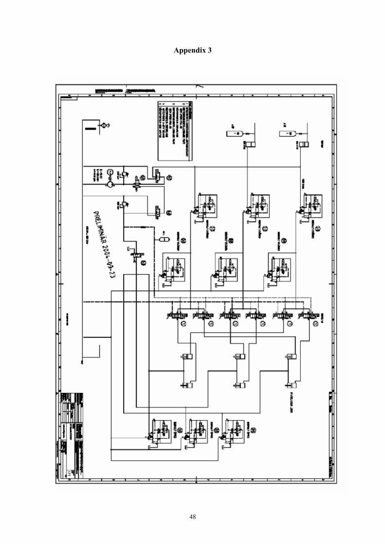
2.6.5 Hydraulic system and Control system The hydraulic system (see the technical drawing in Appendix 3 and a schematic drawing shown in Figure 2-9) is designed for 315 bar working pressure. The press is equipped with six double acting cylinders Ø400/360, arranged in two vertical rows, three in each. The cylinders are double acting to allow the press to return.
The hydraulic flow is generated by highly pressurized nitrogen. The nitrogen drives two media converters with a volume of 150 litres each. The hydraulic flow from the converters is divided into three channels, serving two press cylinders each.
The volume of the gas supply is dependent of what pressure can be allowed in the gas holders. With a starting pressure of 400 bars, the volume needs to be 1500 litres distributed on 30 tanks of 50 litres.
The nitrogen pressure is regulated by a set of TESCOM pressure regulators (4 or 6 in parallel) placed before the media converters,. They regulate the gas pressure to max 330 bars. Max incoming pressure for the regulators is 450 bars.
The gas pressure is converted to a hydraulic pressure in two large converters, 150 liters working volume each (this gives a considerable margin). The outgoing flow is divided into three main channels. The dimension of each main channel is Ø115x15 mm wall thickness.
Each channel is equipped with on/off valves and serves two press cylinders and, after being divided to totally six, parallel channels, six proportional valves are installed. These regulate the hydraulic flow to each separate cylinder. The proportional valves are controlled by stroke indicators, placed on each cylinder.
The control system cycles once every 3: rd millisecond. This guaranties a theoretical accuracy of the front press beam within 0.5 mm. In practice (including elasticity in oil and mechanics) pressure drops and other effects that appear in real performance, the accuracy is expected to be within 1 - 2 mm measured over the front beam.
A minor, electric motor powered hydraulic system is also installed. This system is used to fill up and empty the hydraulic system before and after the test. It is also needed for hydraulic pilot pressure, lubricating flow, returning the press and it will be used to load/reload the nitrogen holders.
In addition, also necessary valves, a hydraulic tank, pipes, pipe supports, filters etc to start up and run the equipment are included.

17
Figure 2-9 Picture showing a schematic view of the hydraulic equipment needed.
2.7 Shearing cylinder 2.7.1 General The shearing cylinder (dark blue in Figure 2-2 and 2-3) is a substitution for the upper part of the drilled rock hole. In reality, an earth quake powered shear movement means that a part of the deposition hole is moving very fast. In order to simulate this, the upper part of the deposit chamber will be made mobile. The shear plane will be located at the upper quarter point of the copper canister.
The shearing cylinder will be designed as a pressure vessel to withstand the swelling pressure (up to 10 MPa) from the contained buffer and the forces from the shear movement.
2.7.2 Shear plane The unmovable part of the deposition hole consists of the rock surface of the drilled hole. The upper part of this hole ends with a heavy steel flange anchored to the rock (see Figure 2-8). This flange shall remain stable during the test and forms the permanent part of the shear plane. Considerable press force will be distributed to the rock structure via this flange.
The top surface of the flange is flat and prepared for low friction. The shearing cylinder, will be placed on this flange. Also the shearing cylinder has a flange, with a flat surface facing the permanent flange. These two creates the shear plane. They are fixed to each other, not to contain the force from the expanding bentonite, but to keep the shear plane fixed and sealed during maturation. The lifting force from the buffer is taken up by the support (see the following chapters).A wedge shaped support ring seals possible leakages. The ring will remain in place during the test. The fixations will be removed prior to the test.

18
2.7.3 Sliding plane The top of the shearing cylinder is equipped with a flanged lid to allow installation of canister and buffer to the hole. The cover will be permanently screwed to the shearing cylinder flange after installation. A wedge shaped supporting ring and a sealing ring prevent leakage.
The supporting plug will be permanent during the test and when the shearing cylinder is moving during the shear test sliding will take place between the cylinder lid and the supporting plug. Since the swelling pressure inside the shearing cylinder will be high, a considerable contact pressure will be created in the sliding plane. Friction forces are, not only disturbing the test results but also difficult to handle.
To minimize these forces a fluid will be pumped into the opening between the two surfaces. The fluid is water, possibly with anticorrosion and lubricating additives. The lifting will be limited to a fraction of a millimetre by the sealing. At a certain height the seal opens and the water is drained out to a collector. The pressure is set to maximum, for example, 90 % of the shearing cylinder pressure.
The water film created, have a very low friction coefficient and the friction force will be minimized. The water flow is created by a separate high pressure water pump with a maximum flow of ca 25 litres per minute.
2.7.4 Upper supporting plug As described in chapter 2.1.1, two different layouts are possible.
Shearing cylinder and press placed below tunnel floor. In the layout of alternative 1 (Figure 2-2), which is most alike a real rock shear situation, the shearing cylinder and the buffer are placed close to their actual level in the deposition hole. The press is arranged in line with the tunnel and the rear press beam is using the rear wall of the second hole for support. The press and the shearing cylinder are located below tunnel floor level. Pre-stressing and adjustment of the downwards directed force on the shearing cylinder are produced by steel wires anchored to the rock.
The steel wires (12 wires, 1800 mm2 each) are connected to a cover beam. The maximum upwards directed force caused by the swelling pressure of the buffer is estimated to about 2400 tons. The wire anchors are designed to allow a preload of totally 2800 tons.
The cover beam and the nut system with hydraulics are designed as a welded box beam. The anchor wires are attached to the beam by a hydraulically pre stressed nut system. The cover beam, the rock anchors and the hydraulic unit are placed above the floor level.
At assembly of the shearing cylinder, the cover beam will be loaded to full load, corresponding to the expected load from the swelling pressure of the matured buffer. The preload will rest partly on the solid rock next to the hole and partly on the shearing cylinder and thus be divided between the rock bed and the shearing cylinder. The load on the shearing cylinder shall be calculated to, for example, 95% of the expected final vertical force from the buffer. The rest of the down force rests on the rock floor and will keep the cover beam fixed vertically throughout the test. Two fixation plates anchored to the tunnel floor in front of the cover beam secures the position of the cover beam in horizontal direction during the test.

19
During maturation, the rising internal pressure will partially unload the shear plane surfaces. By this method, the shear cylinder will be fixed and not move vertically. At the time for the test, the shear surfaces in the shear plane are, more or less, unloaded. In combination with the fluid sliding plane between shearing cylinder and cover beam, the friction forces may be minimized.
Advantages of this alternative: - Known technology for anchoring
- The tunnel is free and accessible - More realistic case
Disadvantages of this alternative: - The shear plane located 2 m below the floor level is difficult to inspect and adjust. - It is difficult and complicated to install the press equipment and shearing cylinder. - The rock around the two holes has been affected and partly cracked and there are bore holes in the near surroundings
Shearing cylinder and press at tunnel floor level. In the layout of alternative 2 (Figure 2-3) the press and the shearing cylinder are placed above the floor level. The press is transverse in relation to the tunnel direction. The rear press beam is supported by the tunnel wall. The rear rock hole is not used and may be filled or covered during the test or as an alternative the lonely hole at the entrance of the drift may be used.
The sliding plane, shear plane and shearing cylinder are the same as in the alternative 1. To keep the shearing cylinder in place when the bentonite buffer expands, a supporting pillar is placed between the shearing cylinder and the tunnel roof. The top of the shearing cylinder is located about 1.8 m above the floor level. A spacer beam is placed on top of the shearing cylinder.
A set of hydraulic cylinders creates the preload on the shearing cylinder supported direct by the tunnel roof via the pillar. The vertical hydraulic system consists of 8 cylinders with 400 tons capacity each. They are designed for max pressure 700 bar and 50 mm stroke and are equipped with a lock nut.
Since the shearing cylinder, the spacer beam, the hydraulics and the pillar are more elastic than the support for alternative 1 (where only the cover beam is included in the compression pile), the system has to be inspected and adjusted during maturation. This may be done by measuring the internal pressure in the shearing cylinder and the axial stroke of it. The hydraulics can be controlled by a computerized system and a flow controlled pumping system.
To prevent the cylinder to move horizontally during the shear test a support will be applied. It has a floating support surface to the spacer and is supported against the tunnel wall. As an alternative, this support may be built as a set of wires to the opposite tunnel wall.

20
Advantages of this alternative:
- Easier erection of the press, shearing cylinder and test object. - Inspections and adjustments of the shearing cylinder, shear plane and press equipment are easy. - Less rock works.
Disadvantages: - Front press beam guidings have to be supported by beams across the tunnel. –Additional frame work required. - The horizontal support to keep the column in place at the shear experiment must be built between the column and the tunnel wall. - The elastic deformation of the vertical support calls for adjustments during maturation.
2.8 Instrumentation The instruments of the ROSE experiment must be designed to measure the hydro-mechanical processes at two extremely different time scales:
• Saturation/maturation phase. This phase will last for about two years. The processes are very slow and the data collection interval will probably be set to 1 hour or less during the test period.
• Shear phase. This phase will last for about 2 seconds. Several thousands of registrations will be done during this time. This means that the demands on the data collection system and the sensors are very high.
Due to the different demands on the data collection it will be necessary to have two separate systems. Also the sensors must be of different types. Many of the sensor types, used in the other field tests at Äspö, are not suitable for the fast measurement during the shearing phase e.g. the sensors using the vibrating wire technique.
A preliminary plan of the sensor positions has been made. The main part of the sensors measuring the maturation of the bentonite will be positioned in a vertical plane perpendicular to the shear direction. The instrument plan is shown in Figure 2-10. Table 2-2 shows a compilation of those sensors. The total pressure will mainly be measured on then walls of the canister and the rock while pore water pressure mainly will be measured on the canister surface because that is where the maturation is expected to be slowest. The relative humidity will be measured with Wescor psychrometers in the centre of the buffer. The experience of Wescor psychrometers is very good at the RH-range expected (95%-100%). The load is planned to be measured in all 12 anchors since it needs to be carefully controlled just before the start of the shear test. The exact position of the sensors is not decided yet so Figure 2-10 should be considered preliminary.

21
Table 2-2. Sensors for measuring maturation of the buffer
Measurement Measuring range Number of sensors
Total pressure 0-10 MPa 14
Pore water pressure 0-2 MPa 7
Relative humidity 95-100% 28
Anchor loads 0-2000 kN 12
The sensors installed to measure during the shear phase will be positioned in a vertical plane located in the shear direction. Figure 2-11 shows the plan. Table 2-3 shows a compilation of those sensors. All measurements are for the moment planned to be made on the surface of the canister and the rock. The exact locations are yet to be decided. Changes regarding the number of sensors and their positions are likely to be done during the detailed planning of the project.
Table 2-3. Sensors for measuring processes during the shear phase
Measurement Measuring range Number of sensors
Total pressure 0-40 MPa 20
Strain on the canister 0-30% 10
Load 0-10 kN 3-6
Displacements 0-30 cm 3
Strain inside the canister Not determined Not decided

22
Filter
Total pressure (14)
Pore pressure (7)
Relative Humidity (28)
Load in anchors (12)
Measuring during maturationTime: about 2-3 years
Measurements perpendicularto shearing direction
Figure 2-10 Schematic drawing of the ROSE experiment showing the instrumentation planned for the saturation phase. The plan is preliminary.

23
Total pressure (20)
Strain gauges (10)
Load (3)
Displacement (3)
Inside canister ?
Strain gauges on rock ?
Measurings during shearing.Time: about 2 seconds
Measurements parallel toshearing direction
Figure 2-11 Schematic drawing of the ROSE experiment showing the instrumentation planned for the shear phase. The plan is preliminary.

24
3 Test procedure
The test can be divided into six quite different and well separated phases:
1. Feasibility study
2. Detailed design and planning of the test
3. Test installation
4. Maturation phase
5. Shear phase
6. Excavation and evaluation
The present report is the result of the feasibility study. The other phases are briefly described as follows:
Detailed design and planning of the test The present feasibility study will be transformed to a test plan and a number of activity plans that in detail describe the design and the equipment. They will also describe the installation procedures. This phase also includes purchase of instruments, equipment for hydraulic force generation during shearing, equipment for enclosing the sheared part of the deposition hole (shearing cylinder as described in chapter 2.5) and the plug. The manufacturing of the canister must also be prepared and ordered.
Test installation Installation of the canister, buffer, shearing cylinder and the plug will probably be done before the installation of the hydraulic force generation since the maturation time is long and can be used for the latter.
The installation must be preceded by a lot of rock work like excavation of the upper part of the rock pillar between the holes, excavation for widening the upper part of the deposition hole, drilling of the holes for the anchors and recesses for installation of instruments on the rock surface. The wetting system with filter mats must also be installed before placement of the bentonite blocks.
Several instruments are planned to be attached to the rock in advance of the buffer installation. Also the upper steel ring simulating the rock surface that is going to be displaced in the shear movement must be placed and fixed in advance.
The actual installation of the buffer and canister will be done in a similar way and sequence as planned for the LASGIT project, which is similar to the way it was done in the Canister Retrieval Test and the Prototype Repository (see e.g. /3-1/):
1. Fastening of the plastic protection sheet on the base of the deposition hole
2. Installation of the bottom bentonite block and the nine rings
3. Deposition of the canister
4. Placement of the two upper blocks

25
5. Removal of the plastic protection sheet
6. Installation of the pellets in the slot between the blocks and the rock
7. Placement of the steel lid, which will be bolted on the top of the steel tube
8. Mounting of the steel plug and locking of the anchors to the plug
9. Start wetting by filling the mats and the pellets filled slot with water
10. Installation of the hydraulic shear force equipment
The latter activity must partly be done before the installation of the buffer and canister but the major part can be done during the maturation phase since the shear equipment will not be used until the shear takes place.
Maturation phase The maturation phase will according to the calculations continue for about two years before the buffer is enough matured. During this period the hydro-mechanical processes will be followed by recording the measured results from all transducers
Shear phase When the buffer is considered to be sufficiently matured, the rock shear can be simulated. Before the shear is carried through the hydraulic shear equipment will be checked by performing a dummy test. A number of procedures will also be fulfilled e.g. for minimizing the friction between the steel lid and the plug. The shear phase will be recorded with the equipment installed for this purpose with a very fast recording rate of about 1000 measurements per second. The exact shear procedure is not decided yet but at the moment the flowing shear movement is planned:
• Shear rate: 0.1 m/second
• Total shear displacement: 0.1 m
The short duration and the fact that there is only one chance to perform the test make it absolutely necessary that the recordings and the mechanical force application work properly. On this reason it will probably be necessary to use at least two independent recording systems. Some additional pre-tests will also be considered.
Excavation and evaluation After finishing the test the equipment will be dismantled and the bentonite carefully excavated. Sampling and subsequent measurement of density and water ratio will give detailed information about the buffer after the test. The canister will be sent to the canister laboratory for investigation of how the shear has affected the canister. Comparison between results and predictions will reveal and hopefully confirm the relevance of the models and the insignificant effect of a rock shear on the canister.
26
4 Predicted outcome
4.1 General The two main phases of the test are the maturation phase and the shear phase. They have both been modelled. The main part of the modelling has been made for other purposes but adapted to the conditions of Rose.
4.2 Maturation phase The buffer conditions are identical to the conditions planned for the LASGIT project with the difference that there will be water supply from the entire rock surface in Rose as opposed to LASGIT where water will only be available at some points on the canister surface and on the rock below and above the canister.
4.2.1 Material model The bentonite has been modelled as a porous material with an initial suction equal to the suction measured for unconfined bentonite at the water ratio used for the blocks. The finite element code ABAQUS has been used for the calculation. The code is described in other reports /4-1, 4-2, 4-3/ and more in detail in the ABAQUS manuals /4-4/.
The basic for the material model is that the pore water and the structure are modelled separately and that the bulk modulus of the pore water and the bulk modulus of the structure are important parameters for the maturation process.
ABAQUS has a special material model for unsaturated soils but this model is not very accurate at high degree of saturation and is neither very good for materials that change their void ratio during the maturation evolution. On this reason an alternative material model adapted for these circumstances has been developed and tested for LASGIT, which has a buffer composition that is almost identical to the one proposed for ROSE.
Pore water (mechanical) Since the material is not saturated but has a degree of saturation of more than 95% this means that the voids in the material contain less than 5% gas. The compressibility of this water is much higher than of gas free water since the gas can be compressed. Unsaturated clay has a pore pressure that is negative. When the pores have been filled with water due to that the gas has been compressed the water can be simulated as being compressed according Eqn 4-1.
dεv=1/(1-Sr) (4-1)
where
dεv= volumetric strain of the water
Sr = degree of saturation
27
The average compressibility of the water when the pore pressure changes from u to 0 is thus
Bw = (-u)/(1-Sr) (4-2)
where
Bw = apparent compressibility of the pore water
u = initial pore pressure of the unsaturated bentonite (negative)
Equation 4-2 has been used to model the pore water.
Structure (mechanical) The clay structure is modelled with a Porous Elastic model /4-1/:
Δe = κΔlnp (4-3)
where
e = void ratio
p = average stress
The parameters for the Porous elastic model are
κ = 0.20 (porous bulk modulus)
ν= 0.4 (Poisson´s ratio)
Hydraulic flow model Darcy´s law has been used to model the water flow
v=Ki (4-4)
where
v = velocity of water
K = hydraulic conductivity
i = hydraulic gradient
The hydraulic conductivity is a function of the void ratio according to Table 4-1.
Table 4-1. Relation between hydraulic conductivity K and void ratio e
e K (m/s)
0.45 1.0⋅10-14 0.70 8.0⋅10-14 1.00 4.0⋅10-13 1.5 2.0⋅10-12 2.00 1.0.10-11
28
Initial conditions Three different bentonite materials will be used. They will have the same properties as described above but have different initial conditions. The blocks above and below the canister will have a void ratio of 0.72 while the rings around the canister will have a lower void ratio (0.65) in order to yield similar density after swelling and homogenisation. The pellets form a mass with an initial high void ratio due to the voids between the pellet granules. Table 4-2 shows the properties and initial conditions.
Table 4-2. Initial properties of the buffer
Bentonite rings (B) Bentonite blocks (A) Pellets
r = 0.525-0.825 m r = 0-0.825 m r = 0.825-0.875 m
e0 = 0.65 e0 = 0.72 e0 = 1.5
u0 = -15 000 kPa u0 = -9 000 kPa u0 = -200 kPa
Sr = 95% Sr = 98% Sr = 90%
4.2.2 Finite element model A simple axial symmetric model with one element row has been used for modelling the maturation. The mesh simulates a radial section through the buffer between the canister and the rock and another section above or below the canister. The boundaries are mechanically locked and hydraulically modelled with a constant water pressure at the rock surface.
4.2.3 Calculations The purpose of the maturation calculations has been to study the time it takes to reach full maturation of the bentonite. Full maturation means that the pore water pressure should be 0 or higher and the swelling pressure completely developed. This also means that all displacements inside the bentonite should have ended and the hydro-mechanical forces should be in equilibrium.
The two horizontal sections described in chapter 4.2.2 and shown in Figue 4-1 have been modelled.
The calculations have been run to complete equilibrium with different modelled applied water pressure at the rock surface.
29
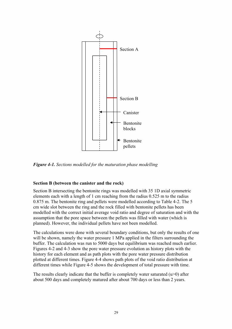
Figure 4-1. Sections modelled for the maturation phase modelling
Section B (between the canister and the rock) Section B intersecting the bentonite rings was modelled with 35 1D axial symmetric elements each with a length of 1 cm reaching from the radius 0.525 m to the radius 0.875 m. The bentonite ring and pellets were modelled according to Table 4-2. The 5 cm wide slot between the ring and the rock filled with bentonite pellets has been modelled with the correct initial average void ratio and degree of saturation and with the assumption that the pore space between the pellets was filled with water (which is planned). However, the individual pellets have not been modelled.
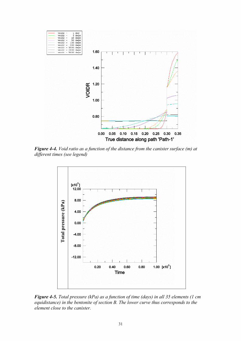
The calculations were done with several boundary conditions, but only the results of one will be shown, namely the water pressure 1 MPa applied in the filters surrounding the buffer. The calculation was run to 5000 days but equilibrium was reached much earlier. Figures 4-2 and 4-3 show the pore water pressure evolution as history plots with the history for each element and as path plots with the pore water pressure distribution plotted at different times. Figure 4-4 shows path plots of the void ratio distribution at different times while Figure 4-5 shows the development of total pressure with time.
The results clearly indicate that the buffer is completely water saturated (u>0) after about 500 days and completely matured after about 700 days or less than 2 years.
Section A
Section B
Bentonite blocks
Bentonite pellets
Canister

30
Figure 4-2. Pore water pressure (kPa) as a function of time (days) in all 35 elements (1 cm equidistance) in the bentonite of section B. The lower curve thus corresponds to the element close to the canister.
Figure 4-3. Pore water pressure (kPa) as a function of the distance from the canister surface (m) at different times (see legend)
31
Figure 4-4. Void ratio as a function of the distance from the canister surface (m) at different times (see legend)
Tot
al p
ress
ure
(kPa
)
Figure 4-5. Total pressure (kPa) as a function of time (days) in all 35 elements (1 cm equidistance) in the bentonite of section B. The lower curve thus corresponds to the element close to the canister.

32
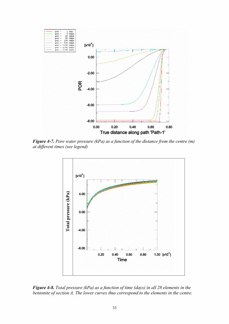
Section A (above or below the canister) Section A intersecting the bentonite blocks radially above or below the canister reaching from the radius 0 m to the radius 0.875 m was modelled with 28 1D axial symmetric elements each with varying length, of which 7 were forming the pellets filled slot and 21 the bentonite block. The bentonite block and pellets were modelled according to Table 4-2. The 5 cm wide slot between the ring and the rock filled with bentonite pellets was modelled in the same way as in section B.
Also these calculations were done with several boundary conditions, but only the results of the one with water pressure 1 MPa applied in the filters are shown. The calculation was run to 1000 days. Figures 4-6 and 4-7 show the pore water pressure evolution as history plots with the history for each element and as path plots with the pore water pressure distribution plotted at different times. Figure 4-8 shows the development of total pressure with time.
The results clearly indicate that the buffer above or below the canister is not completely water saturated or matured even after 1000 days. After 2 years, which is the planned saturation time the pore water pressure is still about -1.5 MPa in the centre above the canister. However, the calculations don’t take into account the 3D-effect that helps the saturation if filter mats are also placed on the top and bottom of the buffer.
Figure 4-6. Pore water pressure (kPa) as a function of time (days) in all 28 elements in the bentonite of section A. The lower curves thus correspond to the elements close to the centre.
33
Figure 4-7. Pore water pressure (kPa) as a function of the distance from the centre (m) at different times (see legend)
Tot
al p
ress
ure
(kPa
)
Figure 4-8. Total pressure (kPa) as a function of time (days) in all 28 elements in the bentonite of section A. The lower curves thus correspond to the elements in the centre.

34
4.3 Shear phase 4.3.1 General The shear phase has earlier been modelled in conjunction with calculations for performance assessment studies. The results are presented in an SKB technical report /1-1/ and in a paper to the MRS conference in Kalmar /1-2/. An updated model for the planned Rose test will be shown. The details of the model will not be shown in this report but can be read about in the referred report.
4.3.2 Finite element mesh The finite element mesh consists of about 500 solid 3D elements. Figure 4-9 shows the entire model of the deposition hole and the three different parts (bentonite buffer, copper canister and cast iron insert). The rock is not modelled but assumed to be completely stiff. The model is symmetric along the axial plane that cuts the deposition hole into two halves. The insert is of the BWR type with 12 channels for fuel assemblies. The shear takes place in a plane perpendicular to the axis of the hole at the ¼ point. The dimensions are the following:
• Deposition hole: diameter 1.75 m and length 6.835 m
• Copper canister: outer diameter 1.05 m and outer length 4.835 m.
• Copper wall thickness: 0.05 m.
• Cast iron insert: diameter 0.949 m and length 4.733 m
• Wall thickness between fuel assemblies: 0.05 m
The 0.5 mm slot between the copper canister and the cast iron insert is thus modelled.

35
Figure 4-9. Element mesh of (from top to bottom) the entire model, the bentonite buffer, the copper canister and the cast iron insert

36
4.3.3 Material models Three materials have been modelled.
Bentonite buffer The bentonite buffer is modelled using only total stresses that don’t include the pore water pressure, the reason being the very fast compression and shear. The stress-strain relation is in ABAQUS described with von Mises stress σj that describes the “shear stress” or deviatoric stress in three dimensions according to Equation 4-5.
σj=(((σ1- σ3)2 + (σ1- σ2)2 + (σ2- σ3)2)/2)1/2 (4-5)
where
σ1, σ2 and σ3 are the major principal stresses
The model includes an elastic part and a plastic part. Table 4-3 shows the elastic and plastic data for the test case. The shear rate 0.1 m/s and the density at saturation 2020 kg/m3 have been considered.
Table 4-3. Elastic-plastic material data for the bentonite buffer at the shear rate 0.1 m/s
Elastic part Plastic part: von Mises stress σj (MPa) at the following plastic strains (εp)
Den-sity
kg/m3 E (MPa) ν εp= 0 εp=
0.002 εp= 0.005
εp= 0.009
εp= 0.013
εp= 0.018
εp= 0.023
εp= 1.0
2020 363 0.49 3.63 4.85 5.57 5.95 6.19 6.3 6.22 6.22
The relation between Mises stress and engineering strain for the test case is shown in Figure 4-10 together with some other cases.
Cast iron and copper The properties of the copper canister and the cast iron insert are also modelled with an elastic plastic model of the Mises stresses. Table 4-4 and Figure 4-11 shows the relations.
Table 4-4. Elastic-plastic material data for the copper and cast iron
Elastic part Plastic part: von Mises stress σj (MPa) at the following plastic strains (εp)
Material
E (MPa) ν εp= 0 εp= 0.2 εp= 0.5 εp= 1.0
Copper 1.2·105 0.33 50 - 200 200
Cast iron 1.5·105 0.32 260 400 - 400

37
Figure 4-10. Material models of the buffer. Mises stress (kPa) as function of strain for the test case (case 2 with the green line) and some other densities
Figure 4-11. Mises stress (kPa) as function of strain for copper and cast iron.
38
4.3.4 Calculation The calculation has been done in two steps. At first the swelling pressure was applied, which mainly resulted in a deformation of the copper canister due to the closure of the 0.5 mm gap between the copper and cast iron. Then the shear has started and continued until a total shear displacement of 20 cm. The applied swelling pressure does not influence the shear calculation in any other respect than the initial deformation and induced stresses.
If the bentonite is modelled to be fixed to the canister by common nodes very high tension stresses will be achieved on the passive side of the canister. In reality the contact can stand very little tension and there will be a gap between the canister and the buffer if high tension is received. In order to take into account the influence of the contact properties the canister has been surrounded by contact elements that cannot withstand any tension. These elements will instead separate in the case of tension stresses. In case of compression the element have Mohr-Coulombs friction properties with the friction coefficient 0.1 (friction angle 5.7 degrees).
4.3.5 Results Effect on the canister The predicted results of the modelling of a shear of 20 cm are shown in Figures 4-12 to 4-16. Figure 4-12 shows the deformed model and a detail of the deformed copper canister. There is an obvious bending of the canister. The effect in form of plastic strain in the steel and copper is shown in Figure 4-13. The maximum plastic strain in the steel is 3-4% and about the same in the central part of the copper canister. However, the maximum plastic strain in the copper is much higher in the lid, where it is up to 20% although it is very local and not seen in the picture.
Effect on the buffer Figure 4-14 shows the plastic strain in the buffer and the average total stress in the buffer after 20 cm shear. The buffer plasticizes very much with large parts of the region around the shear plane exposed to plastic strains higher than 20%. The stresses are also very high with a total average stress higher than 40 MPa at the active part of the canister.
Stresses on the shear cylinder
Figure 4-15 shows the total force required for the shear as a function of the shear displacement. Almost 20 000 kN (2 000 tons) are required. Almost all force is required already after 5 cm shear after which the force does not increase very much due to that the buffer is largely plasticized and cannot withstand higher shear stresses.
Figure 4-16 shows the pressure on the inner surface of the shear cylinder. These relations have been used for the design of the hydraulic presses and the shear cylinder.

39
4.3.6 Conclusions The modelling of the maturation phase and the shear phase shows that
• The maturation can be finished in 2 years but that requires wetting also from mats on top of and below the buffer blocks
• Shearing of a deposition hole with a buffer material that has a density after completed saturation of 2020 kg/m3 with the shear rate 0.1 m/s causes a plastic strain on the steel insert and the copper canister of 3-4%
• Locally the copper lid seems to have a plastic strain of up to 20% (should be further studied)
• The effect of this type of shear is not expected to jeopardize the integrity of the canister
• The total force required to carry through the shearing will be about 20 000 kN
• The calculations can be used for the final design of the set-up.

40
Figure 4-12. Deformed entire model (upper) and deformed copper canister (lower) after 20 cm shear displacement. The plotted deformations of the copper canister have been increased with a factor 5 in order to visualise the effect.

41
Figure 4-13. Plastic strain in the steel insert (upper) and in the copper canister.

42
Figure 4-14. Plastic strain (upper) and average stress (kPa pressure) (lower) in the bentonite buffer. The red colour in the upper figure denotes the part of the buffer subjected to plastic strain higher than 20%. The red colour in the lower picture denotes the part of the buffer subjected to an average stress higher than 40 MPa.

43
Figure 4-15. Total force on the steel cylinder used for the shear as a function of the shear displacement
Figure 4-16. Stresses (kPa) on the inside of the shear cylinder after 20 cm shear

44
5 Evaluation and conclusions
A careful investigation of the possibility to perform a full-scale test that simulates a rock shear through a deposition hole during an earth-quake has been made in this feasibility study. The study has comprised the following investigations:
• Localization of a suitable place for the test
• Modelling of the saturation phase and the shear phase for design purpose and for evaluation of expected results
• Design of the buffer material and the water saturation system in order to reach sufficient maturation of the buffer within about 2 years
• Design of the test set-up for fulfilling the requirements of the test
• Design of the shearing equipment and the pneumatic system for producing a constant rate of deformation of 0.1 m/second
• Design of instrumentation
• Relevant time schedule
The conclusion from the study is that the test can be accomplished with the desired demands for simulating the effect of a critical rock shear. The modelling shows that the maturation can be fulfilled in about 2 years if wetting is supplied from filter mats surrounding the buffer. The modelling also shows that the effect of the rock shear is not detrimental for the canister.
The study also reveals some critical items as
• the friction between the displaced shear cylinder and the surrounding structure that is proposed to be overcome by a highly pressurised water film
• the required unsymmetrical force on the shear cylinder that will be achieved with computer controlled pressure cylinders and unsymmetrical location of the cylinders
• the fast shearing that will be generated by highly pressurized nitrogen that drives the hydraulic flow to the cylinders
Another critical part of the project is the short duration of the actual shear test, which demands that all parts of the system works from start shearing.

45
References
/1-1/ Börgesson L., Johannesson L.-E. and Hernelind J., 2003. Earthquake induced rock shear through a deposition hole. Effect on the canister and buffer. SKB TR-04-02.
/1-2/ Börgesson L., Johannesson L.-E. and Hernelind J., 2004. Earthquake induced rock shear through a deposition hole. Effect on the canister and buffer. MRS Proc. Vol. 807. MRS Kalmar, 2003.
/2-1/ Johannesson L.-E., 2002. Manufacturing of bentonite buffer for the Prototype Repository. ÄHRL IPR-02-19.
/3-1/ Börgesson L., Gunnarsson D., Johannesson L.-E., & Sandén T., 2002. Prototype Repository. Installation of buffer, canister and instaruments in Section 1. ÄHRL IPR-02-23.
/4-1/ Börgesson L, Johannesson L-E, Sandén T, Hernelind J, 1995. Modelling of the physical behaviour of water saturated clay barriers. Laboratory tests, material models and finite element application. SKB Technical Report TR 95-20, SKB, Stockholm.
/4-2/ Börgesson L., Hernelind J., 1999. Coupled thermo-hydro-mechanical calculations of the water saturation phase of a KBS-3H deposition hole. Influence of hydraulic rock properties on the water saturation phase. SKB TR-99-41.
/4-3/ Börgesson L., Hernelind J, & Ludvigsson J.-E., 2004. Modelling of FEBEX in situ test. Coupled thermo-hydro-mechanical analyses of the buffer and the rock. In print.
/4-4/ ABAQUS manuals. ABAQUS Inc.
Appendices
Appendix 1. Technical drawing of Test layout 1
Appendix 2 Technical drawing of Test layout 2
Appendix 3 Technical drawing of the hydraulic system

46
Appendix 1

47
Appendix 2
48
Appendix 3