Äspö planning report 2011
TRANSCRIPT

1

2

3
February 2011
RAPPORTNUMMER/REPORT NO. REG.NR/NO.
IPR-10-19 F50K
FÖRFATTARE/AUTHOR DATUM/DATE
Kemakta and
Rebecca Thidell
January 2011
GODKÄNT/APPROVED DATUM/DATE
Mats Ohlsson February 2011

4


6
7
Contents
1 General 9
1.1 Background 9
1.2 Goals 10 1.3 International participation in Äspö HRL 11 1.4 Allocation of experimental sites 12 1.5 Reporting 12
2 Geoscience 13
2.1 General 13 2.2 Äspö Site Descriptive Model 14
2.3 Geology 16 2.3.1 Geological Mapping and Modelling 16
2.3.2 RoCS-II – Method Development of a New Technique for Underground
Surveying 17 2.4 Hydrogeology 18
2.4.1 Hydro Monitoring Programme 18
2.5 Geochemistry 19 2.5.1 Geochemistry Monitoring Programme 20
3 Natural barriers 21
3.1 General 21
3.2 Tracer Retention Understanding Experiments 22 3.2.1 TRUE-1 Completion 23 3.2.2 Follow-up of TRUE Block Scale structures in the Tass-tunnel 23
3.2.3 Bedrock porosity concepts 24 3.3 Colloid Transport Project 25
3.4 Matrix Fluid Chemistry Continuation 28 3.5 Transport Resistance at the Buffer-Rock Interface 29
3.6 Padamot 30 3.7 Fe-oxides in Fractures 31 3.8 Sulphide in repository conditions 32
3.9 Swiw-tests with Synthetic Groundwater 33 3.10 Äspö model for radionuclide sorption 34
3.11 Task Force on Modelling of Groundwater Flow and Transport of Solutes 37 3.12 BRIE – Bentonite Rock Interaction Experiment 39
4 Engineered barriers 41
4.1 General 41 4.2 Prototype Repository 42 4.3 Long Term Test of Buffer Material 44
4.4 Alternative Buffer Materials 45 4.5 Backfill and Plug Test 46
4.6 Canister Retrieval Test 47 4.7 Temperature Buffer Test 48 4.8 KBS-3 Method with Horizontal Emplacement 50 4.9 Large Scale Gas Injection Test 52 4.10 Sealing of Tunnel at Great Depth 55 4.11 In Situ Corrosion Testing of Miniature Canisters 56 4.12 Cleaning and Sealing of Investigation Boreholes 58

8
4.13 Concrete and Clay 59
4.14 Low-pH Programme 60
4.15 Task Force on Engineered Barrier Systems 62
5 Mechanical- and system engineering 67
5.1 General 67 5.2 Technical Development at Äspö HRL 67
5.2.1 Deposition machine 68 5.2.2 Equipment for backfilling 68 5.2.3 Buffer emplacement 68
5.2.4 Multipurpose vehicle 69 5.2.5 Logistics studies 69 5.2.6 Mission control system 70 5.2.7 Transport system for buffer and backfill material 70 5.2.8 Drilling Machine for Deposition Holes 71
6 Äspö facility 73
6.1 General 73 6.2 Pre-investigation in Order for Tunnel Expansion 74 6.3 Bentonite Laboratory 75
6.3.1 Impact of Water inflow on backfill 77 6.4 Facility Operation 79
6.5 Communication Oskarshamn 81
7 Open research and technical development platform, Nova FoU 83
7.1 General 83 7.2 Nova Research and Development Projects 85
7.2.1 Lanthanoids in bedrock fractures 86 7.2.2 Fluorine in surface and ground waters 87
7.2.3 Modelling of groundwater chemistry 88 7.2.4 Geobiology of microbial mats in the Äspö tunnel 90
7.2.5 Coastal modelling 93 7.2.6 3D localisation system of persons, the Alfagate project 94 7.2.7 Integrated fire protection, the Safesite project 95
7.2.8 Utilisation of waste energy, the EoS project 95 7.2.9 Detailed fracture mineral investigations 96
7.2.10 Expert group for the harbour remediation project in Oskarshamn 96 7.2.11 Hydrochemical interaction between a tunnel and its surroundings –
development of prediction models 97
8 International co-operation 99
8.1 General 99 8.2 Andra 99
8.3 BMWi 101 8.4 CRIEPI 104
8.5 JAEA 104 8.6 NWMO 105 8.7 Posiva 106 8.8 KAERI 108 8.9 Nagra 109 8.10 RAWRA 109
9 References 113
9
1 General
1.1 Background
The Äspö Hard Rock Laboratory (HRL), located in the Simpevarp area in the
municipality of Oskarshamn, constitutes an important part of SKB‟s work with design
and construction of a deep geological repository for final disposal of spent nuclear fuel.
This work includes the development and testing of methods for use in the
characterisation of a suitable site. One of the fundamental reasons behind SKB‟s
decision to construct an underground laboratory was to create an opportunity for
research, development and demonstration in a realistic and undisturbed rock
environment down to repository depth. Most of the research is concerned with processes
of importance for the long-term safety of a future final repository and the capability to
model the processes taking place. Demonstration addresses the performance of the
engineered barriers and practical means of constructing a repository and emplacing the
canisters with spent fuel.
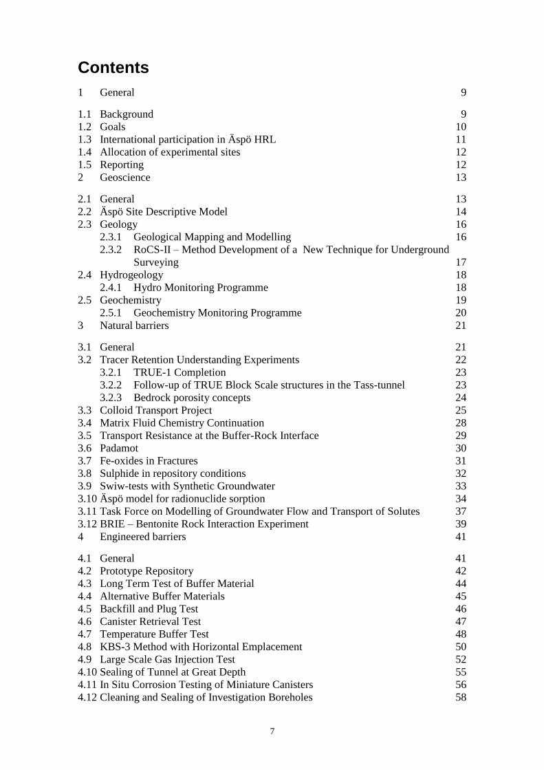
The underground part of the laboratory consists of a tunnel from the Simpevarp
peninsula to the southern part of the island Äspö where the tunnel continues in a spiral
down to a depth of 460 m, see Figure 1-1. The total length of the tunnel is 3,600 m
where the main part of the tunnel has been excavated by conventional drill and blast
technique and the last 400 m have been excavated by a tunnel boring machine (TBM)
with a diameter of 5 m. The underground tunnel is connected to the ground surface
through a hoist shaft and two ventilation shafts.
Figure 1-1. Overview of the Äspö Hard Rock Laboratory.

10
1.2 Goals
To meet the overall time schedule for SKB‟s RD&D work, the following stage goals
were initially defined for the work at the Äspö HRL:
1. Verify pre-investigation methods. Demonstrate that investigations on the ground
surface and in boreholes provide sufficient data on essential safety-related
properties of the rock at repository level.
2. Finalise detailed investigation methodology. Refine and verify the methods and
the technology needed for characterisation of the rock in the detailed site
investigations.
3. Test models for description of the barrier functions at natural conditions.
Further develop and at repository depth test methods and models for description
of groundwater flow, radionuclide migration and chemical conditions during
operation of a repository as well as after closure.
4. Demonstrate technology for and function of important parts of the repository
system. In full scale test, investigate and demonstrate the different components
of importance for the long-term safety of a final repository and show that high
quality can be achieved in design, construction and operation of repository
components.
The tasks in stage goals 1 and 2 were after completion at Äspö HRL transferred to the
Site Investigations Department of SKB. The investigation methodology has hereafter
been developed in the site investigations performed at Simpevarp/Laxemar in the
municipality of Oskarshamn and at Forsmark in the municipality of Östhammar.
In order to reach present goals (3 and 4) the following important tasks are today
performed at the Äspö HRL:
Develop, test, evaluate and demonstrate methods for repository design and
construction as well as deposition of spent nuclear fuel and other long-lived
waste.
Develop and test alternative technology with the potential to reduce costs and
simplify the repository concept without sacrificing quality and safety.
Increase the scientific understanding of the final repository‟s safety margins and
provide data for safety assessments of the long-term safety of the repository.
Provide experience and train personnel for various tasks in the repository.
Provide information to the general public on technology and methods that are
being developed for the final repository.
Participate in international co-operation through the Äspö International Joint
Committee (IJC) as well as bi- and multilateral projects.
In 2007 the inauguration of the Bentonite Laboratory took place and at the laboratory
studies on buffer and backfill materials are performed to complement the studies
performed in the rock laboratory. In addition, Äspö HRL and its resources are available
for national and international environmental research.

11
1.3 International participation in Äspö HRL
The Äspö HRL has so far attracted considerable international interest. During 2011,
eight organisations from seven countries will in addition to SKB participate in the
Äspö HRL or in Äspö HRL-related activities. For each partner the co-operation is based
on a separate agreement between SKB and the organisation in question.
The participating organisations are:
Agence Nationale pour la Gestion des Déchets Radioactifs (Andra), France.
Bundesministerium für Wirtschaft und Technologie (BMWi), Germany.
Central Research Institute of Electric Power Industry (CRIEPI), Japan.
Japan Atomic Energy Agency (JAEA), Japan.
Korea Atomic Energy Research Institute (Kaeri), Korea.
Nuclear Waste Management Organisation (NWMO), Canada.
Posiva Oy, Finland.
Radioactive Waste Repository Authority (Rawra), Czech Republic.
Andra, BMWi, CRIEPI, JAEA, NWMO and Posiva together with SKB form the Äspö
International Joint Committee (IJC), which is responsible for the co-ordination of the
experimental work arising from the international participation. Nagra left the central and
active core of participants 2003 but are nevertheless supporting the Äspö activities and
participates in specific projects. Task Forces are another form of organising the
international work. Several of the international organisations in the Äspö co-operation
participate in the two Äspö Task Forces on (I) Modelling of Groundwater Flow and
Transport of Solutes and (II) Engineered Barrier Systems. SKB also takes part in several
international EC-projects and participates in work within the IAEA framework.
12
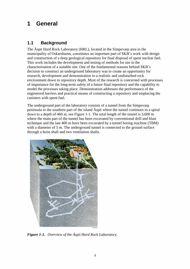
1.4 Allocation of experimental sites
The rock volume and the available underground excavations are divided between the
experiments performed in Äspö HRL. It is essential that the experimental sites are
allocated so that interference between different experiments is minimised. The allo-
cation of the experimental sites in the underground laboratory is shown in Figure 1-2. In
2011 an extension of the underground areas is planned, see Section 6.2.
Figure 1-2. Allocation of experimental sites from -220 m to -460 m level.
1.5 Reporting
SKB‟s plans for research and development of technique during the period 2011–2016
are presented in SKB‟s RD&D-Programme 2010 /SKB 2010/. The information given in
the RD&D-Programme related to Äspö is detailed in the Äspö HRL Planning Report.
This plan is revised annually and the current report gives an overview of the planned
activities for the calendar year 2011. Detailed account of achievements to date for the
activities performed at Äspö can be found in the Äspö HRL Annual Report that is
published in SKB‟s Technical Report series.
Joint international work at Äspö HRL, as well as data and evaluations for specific
experiments and tasks, has earlier been reported in Äspö International Progress Report
series. This series is now completed and the joint international work will be reported
another way. The information will as earlier be summarised in Technical Reports at
times considered appropriate for each project. SKB also endorses publications of results
in international scientific journals. Data collected from experiments and measurements
at Äspö are mainly stored in SKB‟s site characterisation database, Sicada.
13
2 Geoscience
2.1 General
Geoscientific research is a part of the activities at Äspö Hard Rock Laboratory as a
complement and an extension of the stage goals 3 and 4, see Section 1.2. Studies are
performed in both laboratory and field experiments, as well as by modelling work.
The objectives are to:
Establish and develop geoscientific models of the Äspö HRL rock mass and its
properties.
Establish and develop the knowledge of applicable measurement methods.
Experts in the fields of geology, hydrogeology and geochemistry are stationed on site at
Äspö HRL, however, there is a vacancy in rock mechanics. The responsibility of the
experts in respectively geoscientific field involves maintaining and developing the
knowledge and methods of the scientific field as well as geoscientific support to various
projects conducted at Äspö HRL.
The main task within the geoscientific field is the development of an Äspö Site
Descriptive Model (SDM), see Section 2.2. The activities further aim to provide basic
geoscientific data to the experiments and to ensure high quality of experiments and
measurements related to geosciences.
During 2011 there are no major activities planned within the field of rock mechanics
why this project not will be described further within this report.

14
2.2 Äspö Site Descriptive Model
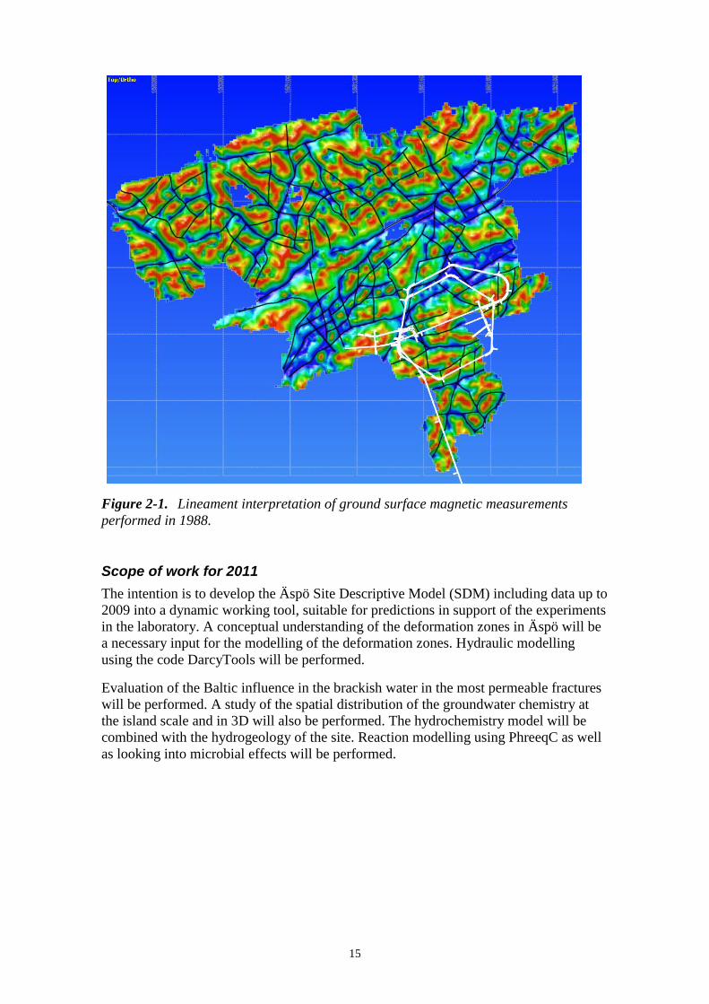
Modelling of deformation zones in Äspö HRL.
The development of an Äspö Site Descriptive Model (SDM) will facilitate the understanding of the geological, hydrogeological and geochemical conditions at the site and the evolution of the conditions during operation of the facility. The SDM also provides basic geoscientific data to support predictions and planning of experiments performed in Äspö HRL. The aim is also to ensure high quality of experiments and measurements related to geosciences.
Present status
The present, most updated descriptive model of the Äspö site includes data collected up
to 2002 and was published in a series of reports in 2005 /Berglund et al. 2003,
Vidstrand 2003, Laaksoharju and Gurban 2003 and Hakami 2003/.
The report concerning the detailed 3D structural geological and hydrogeological model
of the -450 m level is delivered for print. The model is based on available data from
earlier investigations.
Geological single hole interpretation of five surface based boreholes and eight boreholes
drilled from the tunnel has been performed. Hydrogeological single hole interpretation
was performed as well. Lineament interpretation on ground surface magnetic
measurements performed 1988 and topographic data has been performed (Figure 2-1).
All water conductive fractures and water conductive deformation zones have been
plotted in different sections along the tunnel. Hydrogeochemical monitoring data has
been analysed. Explorative analysis of the major components has been and is currently
being done. Plots of Cl, Mg, δ18
O versus depth and time during and after the tunnel
construction have been performed. Multivariate Mixing and Mass balance (M3)
modelling has been used to determine end members and what reactions that needs to be
modelled in PhreeqC.
15
Figure 2-1. Lineament interpretation of ground surface magnetic measurements
performed in 1988.
Scope of work for 2011
The intention is to develop the Äspö Site Descriptive Model (SDM) including data up to
2009 into a dynamic working tool, suitable for predictions in support of the experiments
in the laboratory. A conceptual understanding of the deformation zones in Äspö will be
a necessary input for the modelling of the deformation zones. Hydraulic modelling
using the code DarcyTools will be performed.
Evaluation of the Baltic influence in the brackish water in the most permeable fractures
will be performed. A study of the spatial distribution of the groundwater chemistry at
the island scale and in 3D will also be performed. The hydrochemistry model will be
combined with the hydrogeology of the site. Reaction modelling using PhreeqC as well
as looking into microbial effects will be performed.

16
2.3 Geology
The geological work at Äspö HRL is covering several fields. Major responsibilities are
mapping of tunnels, deposition holes and drill cores, as well as continuous updating of
the geological three-dimensional model of the Äspö rock volume.
In addition, the development of new methods in the field of geology is a major
responsibility. As a part of the latter, the continuation of the Rock Characterisation
System (RoCS) project is being conducted, see Section 2.3.2.
2.3.1 Geological Mapping and Modelling
Checking the rock types (here Ävrö granodiorite) along the open
cut of the Äspö HRL in 2010 (photo: Oskar Sigurdsson).
All rock surfaces and drill cores at Äspö are mapped. This is done in order to increase the understanding of geometries and properties of rock types and structures, which is subsequently used as input in the 3D-modelling of the rock volume together with other input data.
Present status
At present no exposed rock surfaces or drill cores from the Äspö rock volume are
unmapped. Some of the earlier mappings have not yet been entered into the rock
characterisation system TMS (Tunnel Mapping System). The work is, however,
ongoing. The report concerning the geology of the Tass-tunnel has been on review and
adjustments of the report are now in progress. Most tunnels of the Äspö HRL have
earlier been photographed with ordinary film. These analogue photos have some years
ago been converted into digital photos that are now being labelled. A new digital
camera has been mounted in the core logging facilities at Äspö HRL to enable
photography of the drill cores. The camera is connected to the computer used for the
core logging and can to some degree be operated by the latter.
Scope of work for 2011
In order to accommodate new experiments and tests in the Äspö HRL a new tunnel is
planned to be excavated. Core drilling and thus also core logging will commence in the
beginning of 2011. Excavation of the tunnel is planned to start during the beginning of
fall 2011, see Section 6.2. Geological mapping of the tunnel will be performed along
with the excavation. The work with “old” tunnel and deposition hole mappings not yet
digitised and with geological data not entered into the rock characterisation system TMS
will continue. In addition, the maintenance of the TMS will proceed as well as labelling
of photos. Delivery of drawings and data from the TMS will continue as before.

17
2.3.2 RoCS-II – Method Development of a New Technique for Underground Surveying
The company 3GSM gives instructions in the Tass-tunnel about how to use the camera equipment, fall 2010 (photo: Carljohan Hardenby).
A feasibility study concerning geological mapping techniques has been completed /Magnor et al. 2007/. Based on the knowledge from the feasibility study SKB has commenced a new phase of the RoCS project, here referred to as RoCS-II. The purpose is to investigate if a new system for rock characterisation has to be adopted when constructing a final repository. The major reasons for the project are aspects on objectivity of the data collected, traceability of the mappings performed, saving of time required for mapping and data treatment and precision in mapping. These aspects all represent areas where the present mapping technique may not be adequate. The project will concentrate on finding or constructing a new geological underground mapping system. Laser scanning in combination with digital photography and/or photogrammetry will be a part of that system. The resulting mapping system shall operate in a colour 3D environment where the xyz-coordinates are known.
Present status
The RoCS-II project is ongoing (RoCS; Rock Characterization System). After a number
of tests it was decided that photogrammetry will be used for obtaining the 3D models to
be used by the mapping system. Laser scanning in combination with digital
photography has, however, not been totally excluded. The RoCS system should be able
to handle 3D models originating from both photogrammetry and laser scanning in
combination with digital photography.
Photogrammetric equipment including adherent software has been purchased from the
company 3G Software & Measurements (3GSM) that also gave a course in how to
handle the equipment as well as basic knowledge in photogrammetry, see photo above.
The company Ergo data has been assigned to develop the software for the mapping tool
that will be based on the core logging system Boremap. A first simple test version has
already been delivered to SKB.
Scope of work for 2011
The tests of the new photogrammetric equipment will continue during 2011. The
software to be used for the geological mapping of the tunnels will be delivered
during the first half of the year. After that, tests of the whole system will take place
and hopefully it will be ready to use when the planned new tunnel is excavated
in the fall 2011.

18
2.4 Hydrogeology
The objectives of the hydrogeological work are to:
Establish and develop applicable methods for measurement, testing and analysis
for the understanding of the hydrogeological properties of the Äspö HRL rock
mass.
Maintain and develop the understanding of the hydrogeology at Äspö.
Ensure that experiments and measurements in the field of hydrogeology are
performed with high quality.
2.4.1 Hydro Monitoring Programme
The hydro monitoring programme is an important part of the hydro-geological research and a support to the experiments undertaken in Äspö HRL. The monitoring of water level in surface boreholes started in 1987 while the computerised Hydro Monitoring System (HMS) was introduced in 1992. The HMS collects data on-line of pressure, levels, flow and electrical conductivity of the groundwater. The data are recorded by numerous transducers installed in boreholes. The number of boreholes included in the monitoring programme has gradually increased, and comprise boreholes in the tunnel in the Äspö HRL as well as surface boreholes on the islands of Äspö, Ävrö, Mjälen, Bockholmen and some boreholes on the mainland at Laxemar. To date the monitoring programme comprises a total of about 140 boreholes (about 40 surface boreholes and 100 tunnel boreholes). Many boreholes are equipped with inflatable packers, dividing the borehole into sections. Water seeping into the tunnel is diverted to trenches and further to 25 weirs where the flow is measured. Weekly quality checks of preliminary groundwater head data are performed. Absolute calibration of data registered with HMS is performed three to four times annually. This work involves comparison with groundwater levels checked manually in boreholes. The data collected in HMS is transferred to SKB’s site characterisation database, Sicada.
Present status
The hydrogeological monitoring has been ongoing where the monitoring points were
maintained and performing well, particularly the equipment installed in the tunnel.
Efforts to rehabilitate borehole KAS02 have so far been unsuccessful but work on
increasing the number of measuring points along the tunnel have progressed
successfully. The refurbishment of the surface drilled boreholes KAS03 and KAS09
19
was completed and made operational. Other surface drilled Äspö boreholes are only
measured manually or discontinuously.
Part of the monitoring system from the site investigations at Oskarshamn has been
incorporated with Äspö‟s system. The production of quality assurance documents for
hydrogeological measurements has progressed with some being completed. The work
with upgrading of the Äspö site descriptive model has progressed.
Scope of work for 2011
Supporting and corrective measures for the surface borehole is continued with particular
priority of KAS02 and possibly with one of KAS06, KAS07 or KAS08. These are
positioned inside the tunnel spiral and would make a significant enhancement of the
monitoring system due to their strategically position and direction in complementing the
tunnel drilled boreholes.
The monitoring from the Äspö tunnel continues with undiminished efforts. The
monitoring work is reported quarterly through quality control documents and annually
describing the measurement system and results. The work with upgrading of the Äspö
site descriptive model will continue. The production of quality assurance documents
will continue with special emphasis on the method description.
2.5 Geochemistry
The major aims within geochemistry are to:
Establish and develop the understanding of the hydrogeochemical properties of
the Äspö HRL rock volume.
Maintain and develop the knowledge of applicable measuring and analytical
methods.
Ensure that experimental sampling programmes are performed with high quality
and meet overall goals within the field area.
There is a need to develop method descriptions for the actual sampling procedures at
field (underground, excavation of tunnel) for the hydrogeochemical work. In addition,
instructions for procedures for quality assurance of hydro-chemical data to be included
in the site characterisation database Sicada need to be established. The main task is to
develop quality control and quality assurance procedures in the field of hydrochemistry
and geochemistry.

20
2.5.1 Geochemistry Monitoring Programme
Water sampling in a tunnel at Äspö HRL.
The aim of the monitoring programme is to collect and analyse the groundwater chemistry sufficiently to cover the evolution of the hydrochemical conditions in Äspö HRL. The programme is designed to provide information to determine where within the rock mass the hydrogeochemical changes are taking place and at what time stationary conditions are established. After the completion of the site investigations in Oskarshamn, the monitoring programme for core- and percussion boreholes, precipitation, soil tubes and surface water were transferred to the Äspö water chemistry laboratory. In connection with this some sampling sites has been selected after certain criteria such as location on SKB property and satisfying boundary conditions for Äspö SDM, which has resulted in a reduced monitoring programme for the coming years.
Present status
The annual monitoring campaign for groundwater chemistry in the Äspö tunnel started
in December 2010. Cored boreholes were monitored in September and the reporting of
the results from the campaign is ongoing. Selection of percussion boreholes in the
monitoring programme is still under investigation.
Scope of work for 2011
The annual sampling campaign from the tunnel is planned to take place in October
2011. Some changes in the monitoring will take place during the year. All projects at
Äspö HRL can request additional sampling of their sites in the tunnel to be coordinated
within the monitoring programme.
Surface water, soil tubes and precipitation are planned to be sampled bimonthly in the
monitoring programme. Sampling of cored and percussion boreholes drilled from
ground surface will take place during September and October once a year.
21
3 Natural barriers
3.1 General
To meet Stage goal 3, experiments at Äspö HRL are performed at conditions that are
expected to prevail at repository depth, see Section 1.2. The natural barriers consist of
the bedrock and the physical and chemical properties defined by the rock. Emphasis is
put on obtaining data and knowledge that is relevant for the understanding of processes
in the rock which are of major importance for the long-term performance of a
repository.
Models for groundwater flow, radionuclide migration and chemical/biological processes
are developed and tested. The aim is to evaluate the usefulness of models and test
methods for determination of parameters required as input to the models.
The ongoing experiments and projects within the Natural barriers are:
Tracer Retention Understanding Experiments.
Colloid Transport Project.
Matrix Fluid Chemistry Continuation.
Transport Resistance at the Buffer-Rock Interface.
Padamot.
Fe-oxides in Fractures.
Sulphide in repository conditions.
Swiw-tests with Synthetic Groundwater.
Äspö Model for Radionuclide Sorption.
Task Force on Modelling of Groundwater Flow and Transport of Solutes.
BRIE – Bentonite Rock Interaction Experiment.
22
3.2 Tracer Retention Understanding Experiments
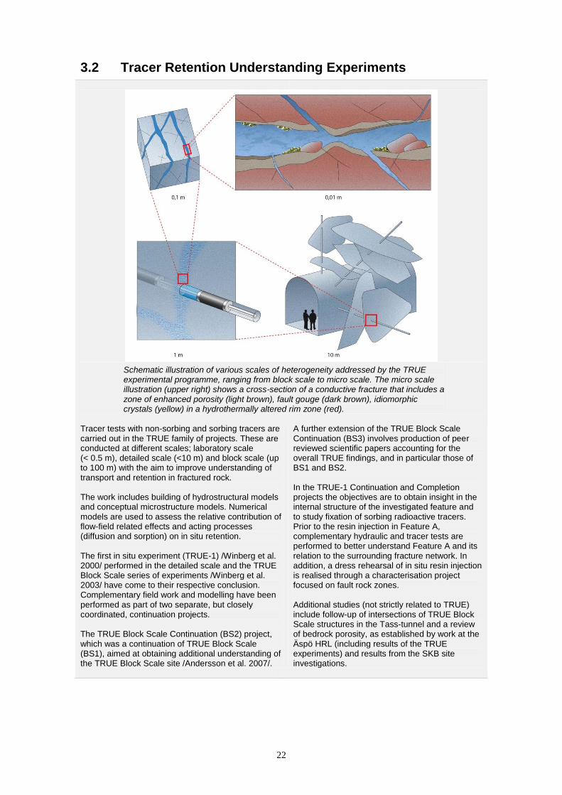
Schematic illustration of various scales of heterogeneity addressed by the TRUE experimental programme, ranging from block scale to micro scale. The micro scale illustration (upper right) shows a cross-section of a conductive fracture that includes a zone of enhanced porosity (light brown), fault gouge (dark brown), idiomorphic crystals (yellow) in a hydrothermally altered rim zone (red).
Tracer tests with non-sorbing and sorbing tracers are carried out in the TRUE family of projects. These are conducted at different scales; laboratory scale (< 0.5 m), detailed scale (<10 m) and block scale (up to 100 m) with the aim to improve understanding of transport and retention in fractured rock. The work includes building of hydrostructural models and conceptual microstructure models. Numerical models are used to assess the relative contribution of flow-field related effects and acting processes (diffusion and sorption) on in situ retention. The first in situ experiment (TRUE-1) /Winberg et al. 2000/ performed in the detailed scale and the TRUE Block Scale series of experiments /Winberg et al. 2003/ have come to their respective conclusion. Complementary field work and modelling have been performed as part of two separate, but closely coordinated, continuation projects. The TRUE Block Scale Continuation (BS2) project, which was a continuation of TRUE Block Scale (BS1), aimed at obtaining additional understanding of the TRUE Block Scale site /Andersson et al. 2007/.
A further extension of the TRUE Block Scale Continuation (BS3) involves production of peer reviewed scientific papers accounting for the overall TRUE findings, and in particular those of BS1 and BS2. In the TRUE-1 Continuation and Completion projects the objectives are to obtain insight in the internal structure of the investigated feature and to study fixation of sorbing radioactive tracers. Prior to the resin injection in Feature A, complementary hydraulic and tracer tests are performed to better understand Feature A and its relation to the surrounding fracture network. In addition, a dress rehearsal of in situ resin injection is realised through a characterisation project focused on fault rock zones. Additional studies (not strictly related to TRUE) include follow-up of intersections of TRUE Block Scale structures in the Tass-tunnel and a review of bedrock porosity, as established by work at the Äspö HRL (including results of the TRUE experiments) and results from the SKB site investigations.

23
3.2.1 TRUE-1 Completion
TRUE-1 Completion is a sub-project of the TRUE-1 Continuation project and is a
complement to already performed and ongoing projects. The main activity within
TRUE-1 Completion was the injection of epoxy with subsequent overcoring of the
fracture and following analyses of pore structure and, if possible, identification of
sorption sites. Furthermore, several complementary in situ experiments were performed
prior to the epoxy injection. These tests were aimed to secure important information
from Feature A and the TRUE-1 site before the destruction of the site.
The general objectives of TRUE-1 Completion are:
To perform epoxy injection and through the succeeding analyses improve the
knowledge of the inner structure of Feature A and to improve the description
and identification of the immobile zones that are involved in the noted retention.
To perform complementary tests with relevance to the SKB site investigation
programme, for instance in situ Kd- and Swiw-test (single well injection
withdrawal).
To improve the knowledge of the immobile zones where the main part of the
noted retention occurs. This is performed by mapping and mineralogical-
chemical characterisation of the sorption sites for Cs.
To update the conceptual micro-structural and retention models of Feature A.
Present status
All field tests, experiments and analysis within the project are completed. During 2010
the work has been focused on evaluations and writing of reports covering the three
major parts of the project; tracer tests, epoxy injection with overcoring and analyses of
core material. None of the reports are yet printed but exists in advanced drafts.
Scope of work for 2011
The plan for 2011 is to finalise a report that summarise the results and findings of
TRUE-1 Completion and to update the conceptual micro-structural and retention models
of Feature A. This report will lead to the finalisation of TRUE-1 Completion.
3.2.2 Follow-up of TRUE Block Scale structures in the Tass-tunnel
The geological and hydrogeological heterogeneity of geological structures, including
fractures and local minor deformation zones (MDZ), has been identified as a remaining
uncertainty in the hydrogeological DFN modelling performed as part of the SKB site
descriptive modelling. The TRUE Block Scale rock volume, and the intercepts of
relevant structures in the Tass-tunnel, offers an opportunity to analyse structure
heterogeneity at different scales as obtained from the TRUE Block Scale investigation
boreholes, Tass-tunnel pilot boreholes and the perimeter of intercepts in the tunnel. A
unified analysis of information from these various sources will provide an Äspö-specific
analogue for description of such heterogeneity. The results can be used as a test bench
for developing new strategies for use of borehole- and tunnel information during the
upcoming detailed characterisation stage.
24
Present status
In situ characterisation performed late 2010 included supplementary geological- and
structural mapping (supported by high dynamic range (HDR) and UV photography),
detailed fracture mineralogical mapping (including sampling and geochemical analyses)
and analysis of hydraulic pressure responses in relevant borehole arrays obtained during
drilling of the Tass pilot boreholes.
Scope of work for 2011
During 2011 focus will lay on integration of results and reporting.
3.2.3 Bedrock porosity concepts
Bedrock porosity (available void space to water or air per unit volume) is an important
entity for various characteristics and properties of crystalline bedrock (e.g. groundwater
flow, solute transport). During the past 15 years valuable contributions, both from in
situ and laboratory experiments, have been obtained on the porosity characteristics of
fractured bedrock from work at the Äspö HRL (e.g. the experiments TRUE, Long term
sorption diffusion and Matrix fluid chemistry) and from site investigations performed at
Forsmark and Oskarshamn. The former results have provided a basis for improved
conceptual descriptions and quantifications. A need has been identified for a unified
description of bedrock porosity spanning all relevant scales, also unifying
nomenclatures employed by the different geoscientific disciplines.
Present status
The planned study is expected to provide, apart from a unified description, an improved
basis for SKB‟s continued work on plans for the detailed investigations in conjunction
with repository development and associated safety assessments.
The specific objective of the planned work is to account for relevant definitions
including necessary scale dependencies. Emphasis is put on establishing bridges
between application and use of porosity concepts in various disciplines (primarily
geology, rock mechanics, hydrogeochemistry, hydrogeology and bedrock transport
properties), making use of graphical illustrations.
Scope of work for 2011
The work planned for 2011 is postponed to 2012 and involves:
Inventory of porosity concepts employed in SKB‟s characterisation and
modelling work.
Normalisation of nomenclature and identification of important concepts.
An integrated conceptualisation will be produced, sustained by supporting
illustrations followed by reporting.
25
3.3 Colloid Transport Project
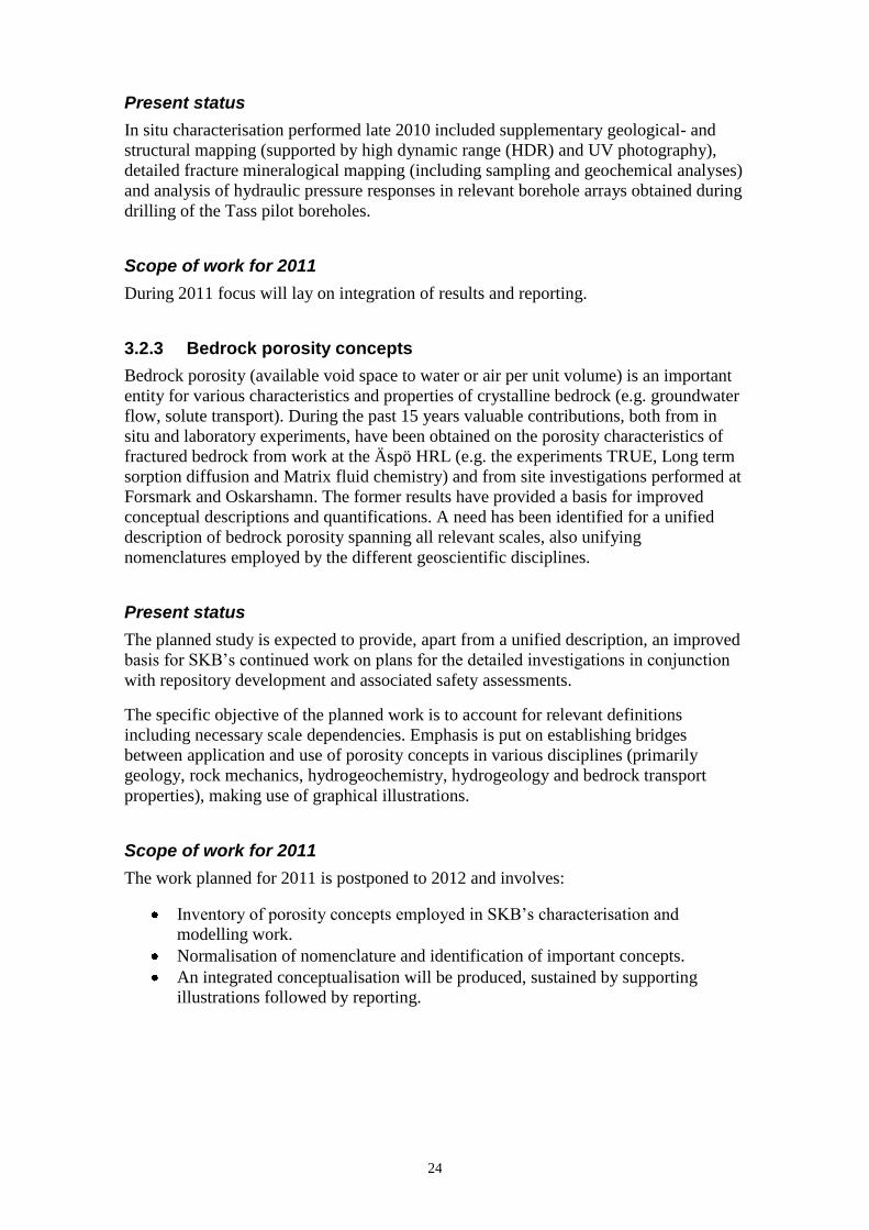
In dilute groundwater the buffer has the potential to release montmorillonite colloids with or without carrying radionuclides.
The Colloid Transport Project is part of the Colloid Formation and Migration (CFM) project steered from Switzerland. The main aim in the CFM is to investigate the ability of the bentonite barrier to release montmorillonite colloids in contact with dilute groundwater. A large bentonite erosion test will be performed at Grimsel test site. The groundwater in Grimsel can be seen as representative for glacial melt water possibly intruding to repository depth. The partners in the project contribute with experimental data from laboratory for support of the design and evaluation of the large scaled in situ test.
Other aims are to:
Study transport and retention mechanisms of montmorillonite colloids in water bearing fractures.
Develop methods for measuring colloid release from the bentonite barrier in situ.
Study sorption of radionuclides to montmorillonite colloids with focus on sorption/desorption kinetics.
Develop predictive models for colloid transport in water bearing fracture.
Present status
The Colloid Dipole Project was initiated in 2005 and continued into the Colloid
Transport project 2008. A finalisation of all the work conducted during 2005-2010 is
now summarised and will be finalised in the beginning of 2011. An extensive amount of
experimental work has been undertaken as well as modelling activities.
The influence of groundwater chemistry, temperature and exposure of -irradiation on
montmorillonite colloid stability has been investigated /Garcia-Garcia 2009; Garcia-
Garcia et al. 2006; Garcia-Garcia et al. 2007; Holmboe et al. 2009/. A short description
of the results from the investigations is given below.

26
Groundwater chemistry
The groundwater chemistry is governing the colloid stability where enhanced
concentrations of Ca2+
and Na+
decreases the time for the colloids to stay in solution. In
Ca-concentrations in the mM range and Na-concentrations in the 10 mM range
montmorillonite colloids will not be stable, but will aggregate and sediment.
Temperature
The spent nuclear fuel will, due to the radiation, heat the canisters and the surrounding
bentonite buffer. From the inner core of the bentonite a temperature gradient will form,
with the highest temperature of about 80 C after 10-100 years of the disposal of the
fuel /Karnland and Birgersson 2006/. It is not obvious from theory how the temperature
will affect colloid stability. At higher temperature the frequency of colliding with each
other will increase and thereby enhancing the chances for aggregation. On the other
hand, the movement in solution of colloids will increase, enhancing stability in solution.
The temperature effect on montmorillonite stability is complex since it will be
influenced by the pH and concentrations of Ca and Na. However, in a groundwater with
pH around 9 and mM ionic strength, the stability of montmorillonite colloids have been
shown to increase with increasing temperature in the temperature range 2-80 C.
Exposure of -irradiation
The bentonite barrier will be exposed to -irradiation due to the radioactive decay in the
spent nuclear fuel. Even though the copper canisters provide shielding, -irradiation will
reach the inner core of the bentonite buffer. This motivates studies of how the
montmorillonite colloids are affected by irradiation. It has been shown experimentally
that the colloid stability increases after exposure of -irradiation. The reasons for these
effects are now further investigated where one factor changing the stability criterion has
been found to be the ratio of Fe2+/
Fe3+
on the colloid surface.
Montmorillonite colloid concentrations outside the buffer
In contact with dilute groundwater the bentonite buffer can release colloids. The colloid
concentration outside the buffer at equilibrium has been investigated in static generation
experiments and found to be in the range of 10 mg/L in mM ionic strength /Garcia-
Garcia et al. 2009/. The same colloid concentration ranges have been found in dynamic
experiments /Vilks 2009/.
Colloid attachment to fracture filling minerals
Colloid transport experiments have been performed in columns of fracture filling
minerals packed in columns. Colloid attachment to the fracture filling minerals could be
detected even under unfavourable conditions with negatively charged minerals and
colloids. The colloid retention in transport experiments could be directly related to the
attachment /Garcia-Garcia et al. 2010/.
Modelling of colloid transport
Modelling exercises for the coming large-scale in-situ bentonite erosion experiment
have been performed as well as data fitting of experimental transport data on varying
scales. These modelling activities form a base for the understanding of the processes
involved in the colloid transport in the water bearing fractures of Grimsel. To define the
source term for colloid release is challenging as well as to describe the transport
retention processes physically and chemically.

27
Scope of work for 2011
Sorption experiments
The sorption of radionuclides to montmorillonite colloids is still an area where data is
lacking. Sorption data is available for the sorption of radionuclides to bulk bentonite
with broad size distributions. Yet, the colloids potentially transporting sorbed
radionuclides are in the lower size range. The sorption capacity is connected to the
specific surface that increases per mass unit with decreasing colloid size accordingly.
Data on sorption of radionuclides to colloids as a function of size is needed and will be
studied intensively in the year of 2011. Further, kinetic sorption data is needed.
Therefore the sorption and desorption with time will be studied. New types of
experiments with non-traditional techniques will be needed to be able to study the fast
sorption and the slower desorption with time.
Colloid transport
Colloid transport in water bearing fractures is complex and is affected by flow, aperture
distribution, surface roughness, groundwater chemistry, colloid characteristics, surface
charge and size distribution. Fracture minerals and the presence of fracture filling
material will also have an impact on the colloid transport. Colloid transport experiments
in varying conditions will therefore continue to be performed within the project to
support with data needed for design and evaluation of the large scaled bentonite erosion
experiment to be performed in Grimsel.

28
3.4 Matrix Fluid Chemistry Continuation
The main objectives of the Matrix Fluid Chemistry experiment are to understand the origin and age of fluids/groundwater in the rock matrix pore space and in micro-fractures, and their possible influence on the chemistry of the groundwater from the more highly permeable bedrock. Matrix fluids are sampled from a borehole drilled into the rock matrix. Fluid inclusions in core samples have also been studied to determine their contribution, if any, to the composition of the matrix fluids/groundwater. The first phase of the project is finalised and reported /Smellie et al. 2003/. The major conclusion is that porewater can successfully be sampled from the rock matrix and there is no major difference in chemistry compared to groundwater from more highly conductive fracture zones in the near-vicinity.
A continuation phase of the project started 2004 and the experimental phase has been completed. The aim of the project is to focus on areas of uncertainty which remain to be addressed:
The nature and extent of connected porewaters in the Äspö bedrock.
The nature and extent of the microfracture groundwaters which penetrate the rock matrix and the influence of these groundwaters on the chemistry of the porewaters.
The confirmation of rock porosity values previously measured in the earlier studies.
Present status
The experimental phase of the project has been completed and is presently being
reported and integrated with the results from the earlier Matrix Fluid Chemistry
Experiment.
Scope of work for 2011
The work during 2011 will consist of integration of results achieved in the two phases
of the project and finalisation of the reporting. A SKB technical report is envisaged.

29
3.5 Transport Resistance at the Buffer-Rock Interface
Results from preliminary tests with diffusion of dye in a 50 mm slot. The images are taken after 41 minutes, 18 hours and 67 hours, respectively. If a canister fails and radionuclides are released, they will diffuse through the bentonite buffer. If there is a fracture intersecting the deposition hole, the water flowing in the fracture will pick up radionuclides from the bentonite buffer. The transport resistance is concentrated to the interface between the bentonite buffer and the rock fracture. The mass transfer resistance due to diffusion resistance in the buffer is estimated to only 6% while the diffusion resistance in the small cross section area of the fracture in the rock is estimated to 94%. The aim of the project is to perform studies to verify the magnitude of this resistance.
Present status
Recently some simple scoping experiments were performed in a variable aperture slit
where a dye was allowed to diffuse into stagnant water. The results partially validate the
“Equivalent flowrate“ Qeq concept as the predicted expansion of the dye front into the
water in the slit agrees with what is expected using the Qeq model concept.
Based on previous experience, the equipment was modified and some new equipment
was built during the spring and summer 2010. Some additional experiments were made
and in one of the experiments a more rapidly diffusing specie were tested. New
equipment, with a 10×10 cm large slit where the dye injection chamber has been
modified in order to facilitate injection of the concentrated dye, was used in another
experiment.
Scope of work for 2011
A set of computer programs will be developed to facilitate and automate the analysis of
the hundreds of pictures taken from the dye diffusion experiment shown in the figure
above. The experimental setup will also be further improved to avoid gas bubbles.
New experiments will be performed with Carmin dye, which has been used so far. In
addition, some inorganic coloured ions will be tested to see if they can be used. The
advantage expected when using these ions is that these have a much larger diffusion
coefficient and potentially could speed up the experiments by a factor of two or more. A
test using potassium permanganate (very intensive colour) failed because it reacted with
the glue and plastic tubes in the equipment.
A model will be made to simulate the propagation of the diffusing dye in the variable
aperture fracture to in detail simulate/predict the propagation of the dye in the fracture
in the experiments.
30
3.6 Padamot
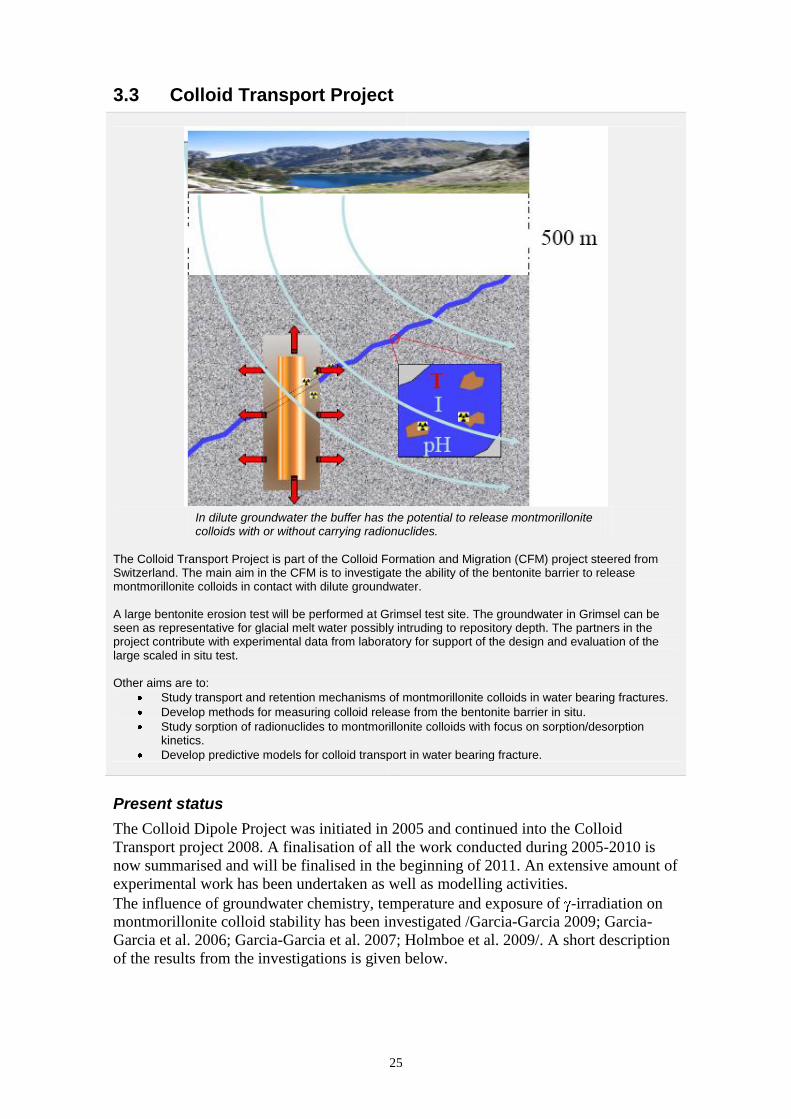
Oxygen entering the bedrock via recharge water will be consumed by organic and inorganic processes along the bedrock fractures. This transition can be detected by studies of uranium and uranium isotopes.
Padamot (Palaeohydrogeological Data Analysis and Model Testing) investigates changes in groundwater conditions as a result of changing climate. Because the long term safety of an underground repository depends on the stability of the repository environment, demonstration that climatic impacts attenuate with depth is important. Currently, scenarios for groundwater evolution relating to climate changes are poorly constrained by data and process understanding.
The EC-part of the project was finalised and reported in 2005. The Padamot continuation project comprises:
Further developments of analytical techniques for uranium series analyses applied on fracture mineral samples and inter-laboratory comparisons.
The use of these analyses for determination of the redox conditions during glacial and postglacial time.
A summary of the experiences from the palaeohydrogeological studies carried out at Äspö.
The analyses are carried out on split samples of fracture material from a surface borehole drilled at Äspö (KAS17). This borehole penetrates the large E-W fracture zone called the Mederhult zone.
Present status
As a SKB/Posiva project within the Greenland Analogue Project, studies of near surface
redox processes are presently studied using the methodology established within the
Padamot and the present Padamot continuation project.
Scope of work for 2011
The methodologies established within the Padamot projects and the results from the
performed investigations are planned to be final reported during 2011.

31
3.7 Fe-oxides in Fractures
Atomic Force Microscopy image of green rust sulphate. Image is 2.5 x 2.5 microns.
Proof of reducing conditions at repository depth is fundamental for the safety assessment of radioactive waste disposals. Fe(II) – minerals are common in the bedrock and along fracture pathways and constitute a considerable reducing capacity together with organic processes. Another area of interest is the radionuclide retention capacity provided by Fe-oxides and –oxyhydroxides in terms of sorption capacity and immobilisation. The basic idea of the project is to examine Fe-oxide fracture linings, in order to explore for suitable palaeo-indicators for their formation conditions, while at the same time learning about the behaviour of trace component uptake in general, both from the natural material as well as through testing of behaviour in controlled parametric studies in the laboratory. Following the original project, a continuation phase with the aim to establish the penetration depth of oxidising water below ground level was started. The oxidising waters may represent present-day recharge, or reflect penetration of glacial melt waters during the last glaciation.
Present status
The project investigations for the continuation phase have been completed and reporting
is the only ongoing activity in the project.
Scope of work for 2011
The work for 2011 will comprise publishing of results from the continuation phase and
to combine this report with earlier published results to produce a final report in SKB‟s
technical report series.
32
3.8 Sulphide in repository conditions
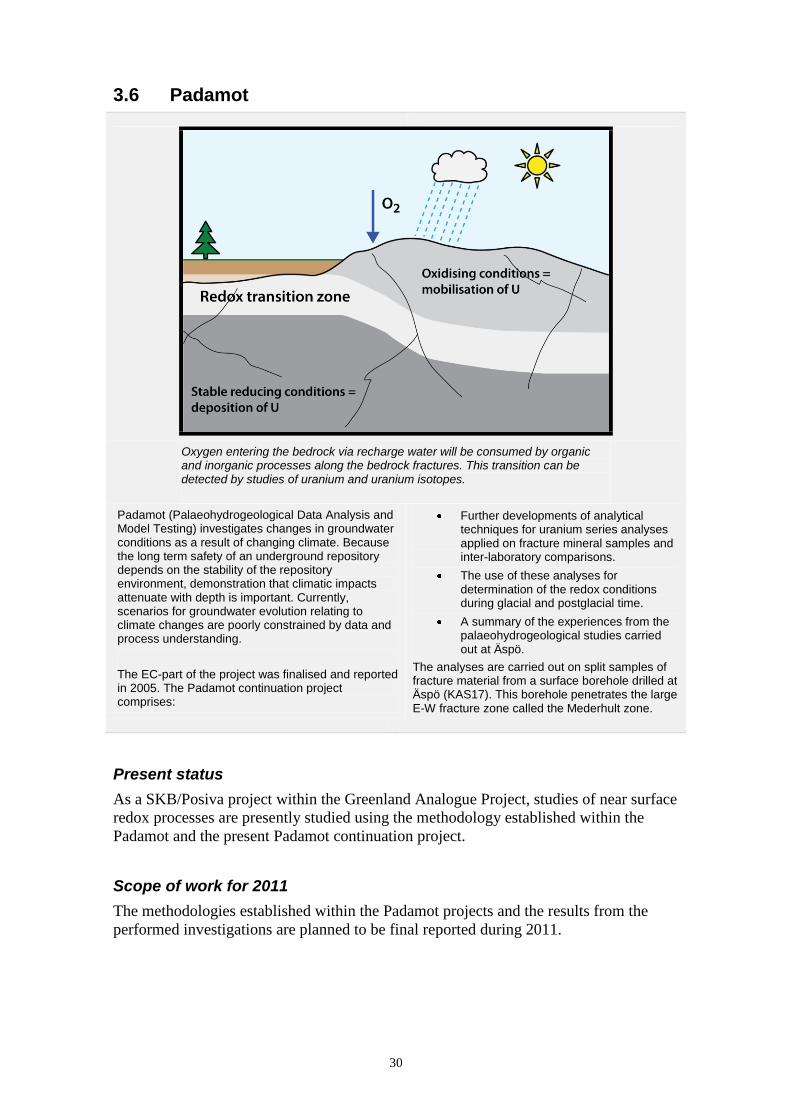
Circulation system for study of sulphide production processes in packed-off borehole sections. The section water is circulated under maintained pressure using a circulation pump located outside the borehole. Tubing ending at the two ends of the section enables circulation / mixing of water before small volumes of water samples are collected and analysed as time-series.
In a repository, knowledge of the groundwater sulphide concentration and its variability is important, since sulphide affects the stability of the copper canister. During the early pre-investigations at Äspö, the site investigations at Laxemar and Forsmark, and the subsequent monitoring programmes, variations in sulphide concentration were obtained. It has been discussed whether drilling and pumping activities and/or installation of monitoring equipment might influence the sulphide concentration. Metabolism of either dissolved organic carbon molecules, or the gases methane and hydrogen by sulphate reducing bacteria may generate sulphide in deep groundwater systems.
Methane and hydrogen are formed in deep geological processes, but hydrogen may also be produced in corrosion processes of metals. Organic carbon molecules may be produced as acetate by acetogenic bacteria from hydrogen and carbon dioxide, but may also exist in equipment materials such as plastics, rubber, etc. The aim of this project is to study the processes behind microbial sulphide production and the regulating factors for dissolved sulphide. The overall aim is to be able to predict the expected variability of the sulphide concentration in a repository environment.
Present status
Circulation experiments are performed in borehole sections KA3110A:1 and
KA3385A:1. The study focuses on analyses of sulphide and other chemical compounds,
microorganisms and dissolved gases. In addition, analyses of stable isotopes (δ2H, δ
13C
and δ18
O) in dissolved gaseous compounds (hydrogen, methane, carbon dioxide) and in
carbonate, sulphide and sulphate are performed in order to determine reaction pathways
and origin of reactants and products.

33
Scope of work for 2011
The borehole equipment (tubing, packers, pipe strings) in KA3110A and KA3385A will
be dismantled and after being visually inspected for any disintegration of plastic
material and indications of corrosion, etc, samples of groundwater will be collected and
analysed for organic carbon content, biofilms, sulphide complexes, plastic softeners and
corrosion products.
Further investigations will include investigations on composition of gases in the rock
matrix, diffusion rates and transport of gas between rock matrix and water-bearing
fractures. Also, studies of sulphide minerals in fractures will be conducted.
3.9 Swiw-tests with Synthetic Groundwater
Injection of tracer in fracture.
The Single Well Injection Withdrawal (Swiw) tests with synthetic groundwater constitute a complement to performed tests and studies on the processes governing retention, e.g. the TRUE experiments as well as Swiw tests performed within the SKB site investigation programme. The general objective of the Swiw test with synthetic groundwater is to increase the understanding of the dominating retention processes and to obtain new information on diffusion. The basic idea is to perform Swiw tests with synthetic groundwater with a somewhat altered composition.
Compared to the natural groundwater at the site chloride, sodium, calcium and potassium are replaced with nitrate, lithium and magnesium. Sorbing as well as non-sorbing tracers are also added during the injection phase of the tests. In the withdrawal phase of the tests the contents of the “natural” tracers (chloride sodium, calcium and potassium) as well as the added tracers in the pumping water is monitored. The combination of tracers, both added and natural, may then provide desired information on diffusion, for example if the diffusion in the rock matrix or in the stagnant zones dominates.
Present status
Borehole KA2858A was in December 2009 selected as the primary test site candidate
for performing Swiw-tests with synthetic groundwater. During the first half of 2010 the
borehole was prepared, re-instrumented and tested in detail with a positive result

34
regarding the suitability as a site for Swiw-tests with synthetic groundwater. A number
of pre-tests were then carried out in order to optimise the main tests. The main tests
were finalised in December 2010. However, no final results in terms of breakthrough
curves are presently available.
Scope of work for 2011
In January 2011, all field activities within the project will be finalised after the removal
of the test equipment. The remaining activities in the project, which is scheduled to take
place during the first half of 2011, are the evaluation and reporting of the tests.
3.10 Äspö model for radionuclide sorption
A chunk of the K-feldspar sample (Sanidine) used in the experiments.
SEM-image of K-feldspar particles from the 250-500 µm fraction.
Today, geochemical retention of radionuclides in the granitic environment is commonly assessed using Kd-modelling. However, this approach relies on fully empirical observations and thus to a limited degree contribute to the evaluation of the conceptual understanding of reactive transport in complex rock environments. In the literature, the process based Component Additivity (CA) approach, which relies on a linear combination of sorption properties of different minerals in a geological material, has been suggested for estimation of sorption properties of the rock. For adoption of this approach to granitic material, the particle size/surface area dependence of radionuclide sorption and effects of grain boundaries need to be resolved. Furthermore, it is desirable to verify sorption of radionuclides to specific minerals within the rock. The overall objective of this project is to formulate and test process quantifying CA models for the geochemical retention of radionuclides, in granitic environments, using a combined laboratory and modelling approach.
Present status
During 2010, the evaluation of the particle size dependency of the specific surface area
of various minerals that was initiated during 2009 has been extended. Surface area
determinations have been carried out for some aluminosilicates (biotite, chlorite,
K-feldspar, plagioclase) that are commonly found in granite, by using gas adsorption
(BET-method) on mineral samples covering a range of particle sizes, from micrometres
to centimetres. Additionally, the specific surface areas of apatite (phosphate mineral),
hornblende (aluminosilicate) and magnetite (iron oxide) have also been determined. For
35
all minerals, increasing specific surface areas with decreasing particle size was found.
The specific surface area of the centimetre-sized chunks of the minerals were in all
cases lower than predicted from the trends observed for the finer, crushed material.
A method for determining porosity of geological samples using nitrogen gas adsorption
has been adopted, tested and refined. The porosities of biotite, chlorite, K-feldspar and
magnetite have been determined for five different particle size fractions, and evaluated
in terms of pore volume and pore size. For all samples, the specific pore volume
increases with decreasing particle size.
Characterisation of the mineral samples used in the experiments has been carried out,
including XRD (X-Ray Diffractometry) examination and determination of chemical
composition during 2010. Currently, SEM (Scanning Electron Microscopy)
investigation of different particle size fractions of some of the minerals is ongoing. The
primary aim of these investigations is to establish characteristic particle forms, surface
properties (such as surface roughness) and potential presence of adhering fine particles.
A secondary aim is to qualitatively assess the particle size distribution within a particle
size fraction. Such information is needed in order to address the dependence of the
specific surface area on particle size, as observed in the BET-determinations.
Furthermore, quantitative investigations of the distribution of particle sizes within a
given particle size fraction of the mineral has been initiated with a particle analyser. In
this method, the particles are stroboscopically photographed while they fall. The
analysis gives information on both particle size distribution and of particle shape.
The planned batch sorption experiments, aiming at studying the particle size
dependency of radionuclide sorption to minerals have been postponed in order to first
gather information about the methodology from preliminary experiments. These will
start early in 2011, and aim at fine-tuning the method. The planned diffusion cell
sorption experiments have been postponed mainly because of porosity and surface area
measurements of the designated mineral pieces are still ongoing. As focus has been on
porosity and specific surface area determinations during the year, and those being
considerably more time consuming than expected, the planned autoradiographic studies
have also been postponed.
During 2010, a subset of the specific surface area data has been presented at the Water
Rock Interaction Conference (WRI-10) in Guanajuato, Mexico, 16th
-20th
of August,
2010, and an article presenting BET-data for chlorite and K-feldspar was published in
the conference proceedings /Dubois et al. 2010a/.
Furthermore, a conference proceedings article following the APSORC ‟09 conference,
which presents BET-data for magnetite and plagioclase, has been revised and accepted
for publication /Dubois et al. 2010b/.
Scope of work for 2011
During 2011, efforts will be focused on compiling the BET and porosity data for the
different minerals. Additionally, similar data will be collected for one or more granite
sample(s) from the Äspö site. Supporting information from SEM and microscopy
inspection of some of the particle size fractions and data of particle size distribution
within the fractions will be used to interpret the observed particle size dependent
specific surface area, aiming to provide predictive models for scaling of sorption
properties between different scales of laboratory experiments.

36
Experimentally, the previously planned systematic study of radionuclide sorption onto
pure minerals as a function of particle size in batch experiments will be given highest
priority. In a set of initial experiments, an appropriate sampling interval will be
determined. The aim of the preliminary set of experiments is also determine how the pH
can be kept as constant as possible in the batches, which is important for the
interpretability of the sorption results.
Subsequent systematic studies will address the Kd-value for sorption of caesium,
strontium, europium and nickel onto 5-7 particle size fractions of some of the more
important minerals in granite and a granite sample at a given pH. If possible, this pH
will be held close to neutral. In addition, it is planned that the Kd-value will be
determined for the same minerals over a range of pH values for a selected particle size
fraction. With results from these experiments, the particles size dependency of the
sorption will be addressed and coupled to the porosity and specific surface area of the
samples.
In-diffusion experiments (diffusion cell experiments) will be initiated using larger
chunks of the minerals and slices of the bore core of the granite sample. The combined
information will be used to address differences in sorption behaviour between crushed
and uncrushed samples for pure minerals and granite from Äspö. The experimental
results will also be used in the formulation of predictive models for sorption in later
stages of the project.

37
3.11 Task Force on Modelling of Groundwater Flow and Transport of Solutes
The Äspö Task Force on Modelling of Groundwater Flow and Transport of Solutes is a forum for the organisations supporting the Äspö HRL to interact in the area of conceptual and numerical modelling of groundwater flow and transport of solutes in fractured rock. The Task Force shall propose, review, evaluate and contribute to the modelling work in the project. In addition, the Task Force shall interact with the principal investigators responsible for carrying out experimental and modelling works for Äspö HRL. The work within the Task Force constitutes an important part of the international co-operation within the Äspö HRL.
Task 7 - Reduction of Performance Assessment uncertainty through modelling of hydraulic tests at Olkiluoto, Finland.
Present status
During 2010, work has been performed in Task 7 (Reduction of Performance
Assessment uncertainty through modelling of hydraulic tests at Olkiluoto, Finland) and
Task 8 (Interaction between engineered and natural barriers). The status of the specific
modelling tasks within Task 7 and Task 8 is given within brackets in Table 3-1.
Task 7 is focusing on methods to quantify uncertainties in PA-type approaches based on
SC-type information; along with being an opportunity to increase the understanding of
the role of fracture zones as boundary conditions for the fracture network and how
compartmentalisation influence the groundwater system. The possibilities to extract
more information from interference tests are also addressed. Task 7 is divided into
several sub-tasks. Updated task descriptions for the sub-tasks 7B and 7C including more
data have been sent out to the modellers.
Task 8 is a joint effort with the Task Force on Engineered Barriers, and will be
addressing the processes at the interface between the rock and the bentonite in
deposition holes. Task 8 has continued in terms of planning and scoping calculations.
The BRIE (Bentonite Rock Interaction Experiment) project, which is coupled to Task 8,
has started up, see Section 3.12.
The 26th
international Task Force meeting was held in Barcelona, Spain, in May. The
presentations were mainly addressing modelling results on sub-tasks within 7B, sub-
task 7C and scoping calculations of Task 8. The discussions on the continuation of Task
7 and also the continuation of Task 8 were constructive. Workshops on Task 7 and 8
have been held in Eurajoki in January and in Lund in December.
38
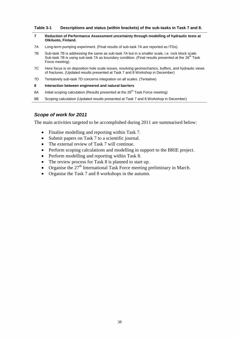
Table 3-1 Descriptions and status (within brackets) of the sub-tasks in Task 7 and 8.
7 Reduction of Performance Assessment uncertainty through modelling of hydraulic tests at Olkiluoto, Finland.
7A Long-term pumping experiment. (Final results of sub-task 7A are reported as ITDs).
7B Sub-task 7B is addressing the same as sub-task 7A but in a smaller scale, i.e. rock block scale. Sub-task 7B is using sub-task 7A as boundary condition. (Final results presented at the 26
th Task
Force meeting).
7C Here focus is on deposition hole scale issues, resolving geomechanics, buffers, and hydraulic views of fractures. (Updated results presented at Task 7 and 8 Workshop in December)
7D Tentatively sub-task 7D concerns integration on all scales. (Tentative)
8 Interaction between engineered and natural barriers
8A Initial scoping calculation (Results presented at the 26th Task Force meeting)
8B Scoping calculation (Updated results presented at Task 7 and 8 Workshop in December)
Scope of work for 2011
The main activities targeted to be accomplished during 2011 are summarised below:
Finalise modelling and reporting within Task 7.
Submit papers on Task 7 to a scientific journal.
The external review of Task 7 will continue.
Perform scoping calculations and modelling in support to the BRIE project.
Perform modelling and reporting within Task 8.
The review process for Task 8 is planned to start up.
Organise the 27th
International Task Force meeting preliminary in March.
Organise the Task 7 and 8 workshops in the autumn.

39
3.12 BRIE – Bentonite Rock Interaction Experiment
The Taso-tunnel and five boreholes (distance 1.5 m) used for initial characterisation and selection of site. BRIE (Bentonite Rock Interaction Experiment) has its focus on the common boundary at the thin interface between the bentonite clay and near-field host rock. BRIE is linked to Task 8 that is a joint effort of the Task Force on Groundwater Flow and Transport and the Task Force on Engineered Barrier Systems.
The combined projects as a whole are intended to lead to:
Scientific understanding of the
exchange of water across the
bentonite-rock interface.
Better predictions of the wetting of
the bentonite buffer.
Better characterisation methods of
the deposition holes.
The experiment is subdivided into two main parts: Part I - describing the selection and characterisation of a test site and two central boreholes.
Part II handling the installation and extraction of the bentonite buffer.
The characterisation will result in a deterministic description of the fracture network at a small scale
( 10 m). This will include all identified fractures (DFN) and the water-bearing part of the fractures (Hydro-DFN).
Present status
Presently, investigations are performed as a basis for selection of the experimental site.
This includes drilling of five boreholes, monitoring of pressure and inflow, hydraulic
tests and core mapping.
Scope of work for 2011
A decision on the suitability of the site will be taken early in 2011 and additional
boreholes will then be drilled for characterisation of the site. This will be followed
by drilling and characterisation of two central boreholes for installation of bentonite
in 2012.

40

41
4 Engineered barriers
4.1 General
To meet stage goal 4, to demonstrate technology for and function of important parts of
the repository barrier system, work is performed at Äspö HRL. This implies translation
of current scientific knowledge and state-of-the-art technology into engineering practice
applicable in a real repository.
It is important that development, testing and demonstration of methods and procedures,
as well as testing and demonstration of repository system performance, are conducted
under realistic conditions and at appropriate scale. A number of large-scale field
experiments and supporting activities are therefore conducted at Äspö HRL. The
experiments focus on different aspects of engineering technology and performance
testing and will together form a major experimental programme.
The ongoing experiments and projects within the Engineered Barriers are:
Prototype Repository.
Long Term Test of Buffer Material.
Alternative Buffer Materials.
Backfill and Plug Test.
Canister Retrieval Test.
Temperature Buffer Test.
KBS-3 method with Horizontal Emplacement.
Large Scale Gas Injection Test.
Sealing of Tunnel at Great Depth.
In Situ Corrosion Testing of Miniature Canisters.
Cleaning and Sealing of Investigation Boreholes.
Concrete and Clay.
Low-pH Programme.
Task Force on Engineered Barrier Systems.
42
4.2 Prototype Repository
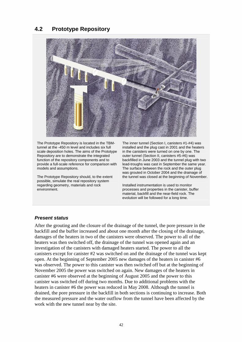
The Prototype Repository is located in the TBM-tunnel at the -450 m level and includes six full scale deposition holes. The aims of the Prototype Repository are to demonstrate the integrated function of the repository components and to provide a full-scale reference for comparison with models and assumptions. The Prototype Repository should, to the extent possible, simulate the real repository system regarding geometry, materials and rock environment.
The inner tunnel (Section I, canisters #1-#4) was installed and the plug cast in 2001 and the heaters in the canisters were turned on one by one. The outer tunnel (Section II, canisters #5-#6) was backfilled in June 2003 and the tunnel plug with two lead-troughs was cast in September the same year. The surface between the rock and the outer plug was grouted in October 2004 and the drainage of the tunnel was closed at the beginning of November. Installed instrumentation is used to monitor processes and properties in the canister, buffer material, backfill and the near-field rock. The evolution will be followed for a long time.
Present status
After the grouting and the closure of the drainage of the tunnel, the pore pressure in the
backfill and the buffer increased and about one month after the closing of the drainage,
damages of the heaters in two of the canisters were observed. The power to all of the
heaters was then switched off, the drainage of the tunnel was opened again and an
investigation of the canisters with damaged heaters started. The power to all the
canisters except for canister #2 was switched on and the drainage of the tunnel was kept
open. At the beginning of September 2005 new damages of the heaters in canister #6
was observed. The power to this canister was then switched off but at the beginning of
November 2005 the power was switched on again. New damages of the heaters in
canister #6 were observed at the beginning of August 2005 and the power to this
canister was switched off during two months. Due to additional problems with the
heaters in canister #6 the power was reduced in May 2008. Although the tunnel is
drained, the pore pressure in the backfill in both sections is continuing to increase. Both
the measured pressure and the water outflow from the tunnel have been affected by the
work with the new tunnel near by the site.

43
The data collection system comprises temperature, total pressure, porewater pressure,
relative humidity and resistivity measurements in buffer and backfill as well as
temperature and water pressure measurements in boreholes in the rock around the
tunnel. Furthermore, rock mechanical measurements are ongoing. The measurements
comprise registration of stress and strain in the rock mass around the two outer
deposition holes. The data from the readings is presented in data reports (two per year).
Chemical measurements in buffer, backfill and surrounding rock are ongoing. Tests for
evaluating the groundwater pressure and groundwater flow in the rock have also been
performed. Acoustic measurements in the rock are ongoing with the purpose to study
how the temperature evolution is affecting the properties of the rock. A thermal FEM
model for the Prototype Repository including the rock, backfill, buffer and the six
canisters has been developed.
Scope of work for 2011
During 2011 the outer plug (120 tons), the water-saturated backfill (900 tons) and the
buffer in deposition holes #6 and #5 (total of 40 tons) will be excavated while extensive
samplings are performed. Approximately 1,000 samples on the backfill and about 3,000
samples on the buffer will be taken to determine water content and density. Further
samples will be analysed in laboratories. In addition 332 installed sensors will be
dismantled, sorted out and controlled. The two canisters will be lifted up and
transported to the Canister Laboratory in Oskarshamn for additional investigations.
The main objectives of the dismantling of the outer section are:
Investigate the density and water saturation of the buffer and backfill.
Investigate the interface between buffer – backfill and between backfill – rock
surface, after 7 years wetting.
Investigate the outer plug.
Measure and examine the canisters (positions, mechanical stress, corrosion).
Investigate the bedrock after dismantling.
Study biological and chemical activities in the buffer and backfill.
Study possible changes of the buffer material caused by the temperature and the
saturation process.
Modelling of the hydraulic process in the rock mass surrounding the experiment prior to
the installation will be finalised. The THM-modelling of the buffer and backfill close to
the deposition hole #6 will be made as a task within EBS Task Force. This work will be
finalised during 2011.
Laboratory investigations of the excavated buffer and the backfill from the outer section
will start during 2011. The instrument readings and the chemical measurements in
buffer, backfill and surrounding rock for the inner section will continue.

44
4.3 Long Term Test of Buffer Material
Schematic drawing of a test parcel.
The project Long Term Test of Buffer Material (Lot) aims to validate models and hypotheses concerning mineralogy and physical properties in a bentonite buffer. Seven test parcels containing heater, central tube, clay buffer, instruments and parameter controlling equipment have been placed in boreholes with a diameter of 300 mm and a depth of around 4 m. Temperature, total pressure, water pressure and water content, are measured during the heating period. At termination of the tests, the parcels are extracted by overlapping core-drilling outside the original borehole. The water distribution in the clay is determined and subsequent well-defined mineralogical analyses and physical testing of the buffer material are made. The test parcels are also used to study other processes in bentonite such as cation diffusion, microbiology, copper corrosion and under conditions similar to those expected in a KBS-3 repository.
Present status
Four test parcels have been retrieved and analysed so far. The remaining three parcels
are well functioning and have been heated to target temperatures for almost ten years
(Table 4-1). The report concerning the A2 parcel test has been published /Karnland et
al. 2009/. The main results have been presented at international meetings in France and
in Japan. The report concerning the A0 parcel test has been finalised and will be
published in January 2011.
Scope of work for 2011
Only operation and maintenance work will be performed during 2011, and no uptake of
parcels is planned.
Table 4-1 Ongoing tests in the series Long Term Test of Buffer Material.
Type No. max T (°C) Controlled parameter Time (years) Remark
A 3 120-150 T >>5 Ongoing
S 2 90 T >5 Ongoing
S 3 90 T >>5 Ongoing
A = adverse conditions, S = standard conditions, T = temperature.

45
4.4 Alternative Buffer Materials
Installation of one of the three test parcels. The photo illustrates the mixing of different compacted buffer blocks.
In the Alternative Buffer Material test, ABM, eleven buffer materials with different amount of swelling clay minerals, smectite counter ions and various accessory minerals are tested. The test is performed in the rock at repository conditions except for the scale and the adverse conditions (the target temperature is set to 130°C). Three parcels containing heater, central tube, pre-compacted clay, buffer, instruments and parameter controlling equipment have been emplaced in vertical boreholes with a diameter of 300 mm and a depth of 3 m. Parallel to the field tests, laboratory analyses of the reference materials are going on. The project is carried out using materials that are possible as future buffer candidate materials. The main objectives are to:
Compare different buffer materials concerning mineral stability and physical properties, both in laboratory tests of the reference materials but also after exposure in field tests.
Study the interaction between metallic iron and bentonite. This is possible since the central heaters are placed in tubes made of straight carbon steel.
Present status
Three test parcels were installed and the operational phase initiated in November 2006.
Test parcel 1 was retrieved in May 2009 after about 1.5 year of operation at a
temperature of 130°C. The buffer blocks were divided and samples sent out to the
different participating organisations (Andra, BGR, JAEA, Nagra, Posiva, RAWRA and
AECL) for analysis.
The work with compiling a report describing analyses of reference materials,
termination of test parcel 1 and the performed analyses of material from this test
parcel is ongoing. The two remaining test parcels are running at the intended
temperature (130°C).
Scope of work for 2011
Further mineralogical analyses are planned to be performed on material from test
parcel 1. A special study aiming at comparing results from different laboratories
regarding cation exchange capacity (CEC) measurements is also ongoing. Reference
material from four different bentonite materials have been homogenised in laboratory
and sent out to the participating laboratories. The CU-trien method, for determining the
CEC, is described in detail in order to ensure that the management by the laboratories is
equivalent. This CEC investigation is organised by BGR.
A project meeting will be held in the beginning of May at Äspö HRL.
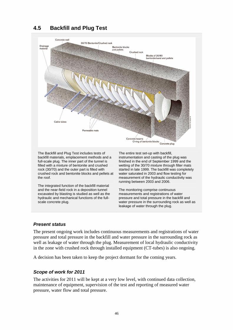
46
4.5 Backfill and Plug Test
The Backfill and Plug Test includes tests of backfill materials, emplacement methods and a full-scale plug. The inner part of the tunnel is filled with a mixture of bentonite and crushed rock (30/70) and the outer part is filled with crushed rock and bentonite blocks and pellets at the roof. The integrated function of the backfill material and the near-field rock in a deposition tunnel excavated by blasting is studied as well as the hydraulic and mechanical functions of the full-scale concrete plug.
The entire test set-up with backfill, instrumentation and casting of the plug was finished in the end of September 1999 and the wetting of the 30/70 mixture through filter mats started in late 1999. The backfill was completely water saturated in 2003 and flow testing for measurement of the hydraulic conductivity was running between 2003 and 2006. The monitoring comprise continuous measurements and registrations of water pressure and total pressure in the backfill and water pressure in the surrounding rock as well as leakage of water through the plug.
Present status
The present ongoing work includes continuous measurements and registrations of water
pressure and total pressure in the backfill and water pressure in the surrounding rock as
well as leakage of water through the plug. Measurement of local hydraulic conductivity
in the zone with crushed rock through installed equipment (CT-tubes) is also ongoing.
A decision has been taken to keep the project dormant for the coming years.
Scope of work for 2011
The activities for 2011 will be kept at a very low level, with continued data collection,
maintenance of equipment, supervision of the test and reporting of measured water
pressure, water flow and total pressure.

47
4.6 Canister Retrieval Test
The Canister Retrieval Test is aiming at demonstrating the readiness for recovering of emplaced canisters also after the time when the bentonite is fully saturated. In the Canister Retrieval Test two full-scale deposition holes have been drilled, at the -420 m level, for the purpose of testing technology for retrieval of canisters after the buffer has become saturated. These holes have been used for studies of the drilling process and the rock mechanical consequences of drilling the holes. Canister and bentonite blocks were emplaced in one of the holes in 2000 and the hole was sealed with a plug, heater turned on and artificial water supply to saturate the buffer started. In January 2006 the retrieval phase was initiated and the canister was successfully retrieved in May 2006. The saturation phase had, at that time, been running for more than five years with continuous measurements of the wetting process, temperature, stresses and strains.
Present status
The buffer analyses are completed. The aim with these analyses is to investigate
changes in material characteristics (chemical, hydraulic and mechanical) by comparing
properties of buffer samples retrieved from the Canister Retrieval Test (CRT) with those
of reference material. A report and an article describing the buffer analyses are close to
be finalised.
A manuscript, “Homogenization of engineered barriers, simulations verified against
Canister Retrieval Test data”, is accepted for being published in the proceedings of
“Clays in Natural & Engineered Barriers for Radioactive Waste Confinement” (Nantes,
27th
March – 1st April, 2010).
Scope of work for 2011
During 2011 the report and the article describing the buffer analyses will be finalised
and a report on the modelling of CRT in the EBS Task Force will be written.
Predictive modelling of the Prototype Repository has lately been, and will be, prioritised
due to the upcoming dismantling of the outer section. The modelling of the CRT in the
EBS Task Force will hopefully be continued in the second half of 2011. The aim is now
to simulate the experiment at full scale.

48
4.7 Temperature Buffer Test
The French organisation Andra carries out the Temperature Buffer Test (TBT) at Äspö HRL in co-operation with SKB. The aims of the TBT are to evaluate the benefits of extending the current understanding of the THM behaviour of engineered barriers during the water saturation transient to include high temperatures, above 100°C. The scientific background to the project relies on results from large-scale field tests on engineered barrier systems, notably Canister Retrieval Test, Prototype Repository and Febex (Grimsel Test Site). The test has been located in the same test area as the Canister Retrieval Test, which is in the main test area at the -420 m level. The experiment included two heaters in the axis of the deposition hole, one on top of the other, separated by a compacted bentonite block. The heaters were 3 m long and 610 mm in diameter and were constructed in carbon steel. Each one simulated a different type of confinement system: a bentonite buffer only (bottom section) and a bentonite buffer with inner sand shield (upper section). An artificial water pressure was applied in a slot between the buffer and rock, which was filled with sand and functioned as a filter. The test was installed during the spring 2003 and the test was dismantled during the winter of 2009/2010. Recorded data has been transferred by a link from Äspö to Andra’s head office in Paris.
Present status
The experimental setup has been characterised by stationary, well defined, boundary
conditions. Starting in March/April 2003 with 1,500 W from each heater, the power was
increased to 1,600 W in June 2006 as a compensation for the dismantling of the Canister
Retrieval Test. In order to promote chemical and mineralogical alteration processes in
the lower package, the thermal output from the heaters was changed at the end of 2007.
The lower heater was increased 2,000 W, while the upper was decreased 1,000 W.
Due to the dismantling operation, the heating and the hydration was terminated in
August 2009.
The upper part of the test, i.e. all the bentonite and sand down to Cylinder 2 as well as
the upper heater, was sampled and removed during the last two months of 2009. The
upper heater was retrieved after the sand in the shield had been removed, which could
be accomplished with an industrial vacuum cleaner after loosening the material through
mechanical means (hammer drill and core machine). The lower part of the test was
sampled and removed during the period from January to April 2010.
Core drilling (with 50 mm diameter cores) was used as the main method for sampling
and partitioning of bentonite blocks. The plan was to take core samples at 50 mm
distance in four perpendicular directions in each block. These core samples have been

49
analysed for density and water content at the Bentonite Laboratory at Äspö. In addition,
two pieces (so called big sectors) representing the entire radial distance were taken from
each block. These big sectors are devoted for the hydro-mechanical and chemical
characterisation programme, and this work is now ongoing. Several sensors have been
retrieved and tested. Two big undisturbed interface samples with bentonite and iron
have been taken; one on top of the lower heater, and one on the lower end of the vertical
side of the heater. Four cores with interface samples with bentonite/concrete were taken
from Cylinder 1 and the bottom plate.
During the course of the project the evaluation of THM processes has been made
through analysis of sensors data (for the latest report, see /Goudarzi et al. 2009/),
through numerical modelling /Hökmark et al. 2007, Åkesson 2006a/ and through
evaluation and numerical modelling of parallel lab-scale mock-up tests /Åkesson 2006b,
Åkesson 2008, Åkesson et al. 2009/. With access to the data from the dismantling
operation, the THM modelling of the field test was resumed in the end of 2010.
The following reports have been completed and are now in draft form: i) the report from
the dismantling operation, ii) the report from the base characterisation programme
(water content and density), iii) the installation report and iv) the last sensors data report
(including the reporting of the sensor function control).
Scope of work for 2011
The plan is to continue with and finalise the hydro-mechanical and chemical
characterisation programme as well as the THM modelling during the first half of 2011.
A final report will also be prepared. The draft reports listed above are ready for a review
process and will be published during 2011.

50
4.8 KBS-3 Method with Horizontal Emplacement
The possibility to modify the reference KBS-3 method and make serial deposition of canisters in long horizontal deposition holes (KBS-3H), instead of deposition of single canisters in vertical deposition holes (KBS-3V), is studied in this project. One reason for proposing the change is that the deposition tunnels in KBS-3V are not needed if the canisters are disposed in long horizontal deposition holes and the excavated rock volume and the amount of backfill can be considerably reduced. This in turn reduces the environmental impact during the construction of the repository and also the construction costs. The site for the demonstration of the method is located at -220 m level. A niche with a height of about 8 m and a bottom area of 25×15 m forms the work area.
Two horizontal deposition holes have been excavated, one short with a length of about 15 m and one long with a length of about 95 m. The deposition equipment is being tested in the long hole and the short hole will be used for testing of different drift components. The project is a joint project between SKB and Posiva. The current phase of the project; “Complementary studies of horizontal emplace-ment KBS-3H” is ongoing. The main goal of the 2011-2014 project phase “KBS-3H System design” is to reach the system design level of the KBS-3H design and produce the KBS-3H basis required to prepare a PSAR and a subsequent comparison between KBS-3H and KBS-3V.
Present status
Activities aiming at testing the KBS-3H design and components at the -220 m level
have continued during 2010. The deposition machine has been operated with good
results. To further increase reliability and robustness an analysis has been carried out
and the outcome resulted in suggestions on mechanical and sensor upgrades. The
upgrade of the machine will be done during 2011.
Testing of the compartment plug has continued with good results and the plug fulfils the
leakage criterion with a margin.
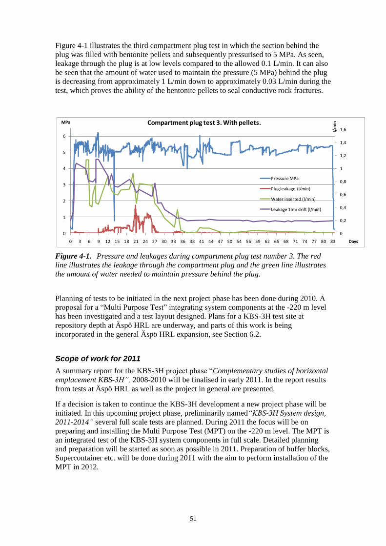
51
Figure 4-1 illustrates the third compartment plug test in which the section behind the
plug was filled with bentonite pellets and subsequently pressurised to 5 MPa. As seen,
leakage through the plug is at low levels compared to the allowed 0.1 L/min. It can also
be seen that the amount of water used to maintain the pressure (5 MPa) behind the plug
is decreasing from approximately 1 L/min down to approximately 0.03 L/min during the
test, which proves the ability of the bentonite pellets to seal conductive rock fractures.
Figure 4-1. Pressure and leakages during compartment plug test number 3. The red
line illustrates the leakage through the compartment plug and the green line illustrates
the amount of water needed to maintain pressure behind the plug.
Planning of tests to be initiated in the next project phase has been done during 2010. A
proposal for a “Multi Purpose Test” integrating system components at the -220 m level
has been investigated and a test layout designed. Plans for a KBS-3H test site at
repository depth at Äspö HRL are underway, and parts of this work is being
incorporated in the general Äspö HRL expansion, see Section 6.2.
Scope of work for 2011
A summary report for the KBS-3H project phase “Complementary studies of horizontal
emplacement KBS-3H”, 2008-2010 will be finalised in early 2011. In the report results
from tests at Äspö HRL as well as the project in general are presented.
If a decision is taken to continue the KBS-3H development a new project phase will be
initiated. In this upcoming project phase, preliminarily named“KBS-3H System design,
2011-2014” several full scale tests are planned. During 2011 the focus will be on
preparing and installing the Multi Purpose Test (MPT) on the -220 m level. The MPT is
an integrated test of the KBS-3H system components in full scale. Detailed planning
and preparation will be started as soon as possible in 2011. Preparation of buffer blocks,
Supercontainer etc. will be done during 2011 with the aim to perform installation of the
MPT in 2012.
0
0,2
0,4
0,6
0,8
1
1,2
1,4
1,6
0
1
2
3
4
5
6
0 3 6 9 12 15 18 21 24 27 30 33 36 38 41 44 47 50 54 56 59 62 65 68 71 74 77 80 83
l/m
inMPa
Days
Compartment plug test 3. With pellets.
Pressure MPa
Plug leakage (l/min)
Water inserted (l/min)
Leakage 15m drift (l/min)

52
The planned deposition machine upgrade and subsequent testing should also be initiated
during 2011 with aim to be completed well ahead of the installation of the MPT in
which the machine is needed.
Tests of KBS-3H pilot hole drilling could possibly also be incorporated in the
Äspö HRL expansion during 2011.
4.9 Large Scale Gas Injection Test
The Large-scale gas injection test (Lasgit) 420 m below ground at Äspö HRL. Current knowledge pertaining to the movement of gas in a compacted bentonite buffer is based on small-scale laboratory studies. These diagnostic tests are designed to address specific issues relating to gas migration and its long-term effect on the hydro-mechanical performance of the buffer clay. Laboratory studies have been used to develop process models to assess the likely implications of gas flow in a hard-rock repository system. While significant improvements in our understanding of the gas-buffer system have taken place, a number of important uncertainties remain. Central to these is the issue of scale and its effect on the mechanisms and process governing gas flow in compact bentonite. The question of scale-dependency in both hydration and gas phases of the test history are key issues in the development and validation of process models aimed at repository performance assessment. To address these issues, a Large Scale Gas Injection Test (Lasgit) has been initiated.
Its objectives are:
Perform and interpret a large scale gas injection test based on the KBS-3V design concept.
Examine issues relating to up-scaling and its effect on gas migration and buffer performance.
Provide information on the process of hydration and gas migration.
Provide high-quality test data to test/validate modelling approaches.
In February 2005 the deposition hole was closed and the hydration of the buffer initiated. During 2007 preliminary hydraulic and gas transport tests were performed. These were repeated in 2009-2010, giving information on the maturation of the buffer in order to examine the temporal evolution of these properties. When the buffer is fully-hydrated a comprehensive series of gas injection tests will be undertaken to examine the mechanisms governing gas flow in KBS-3 bentonite.
53
Present status
Activities in 2010 were dominated by the completion of the second series of gas and
hydraulic tests that were conducted during the ongoing hydration of the bentonite
buffer.
The first half of 2010 involved the continuation of the gas testing that was started on the
28th
of May 2009 (day 1577). As in previous gas testing histories, filter FL903 in the
lower filter array of the canister was selected. Neon was the gas injection medium so
that leakage to the host rock could be monitored. The gas injection pressure and flow
into the clay showed that the system continually over- and under-shot as the pressure
changes with time, as previously reported for laboratory experiments.
At approximately day 1810 flow into the clay increased for a second time, resulting in a
drop of pressure in filter FL903 of about 300 kPa. Gas flow reduced and pressure in
FL903 slowly increased once more to return to approximately 5,600 kPa by day 1830,
where once again pressure slowly decayed to 5,520 kPa (over- and under-shooting).
Gas flow into the clay increased for a third time, with a major flux pulse on day 1853.
This resulted in a considerable loss of filter pressure, which was aided by a leaking
valve on the injection pump. On day 1864 the valve was closed fully and the pressure in
FL903 began to rise. While this event was not planned, it was effectively a pressure
shut-in test and gave the opportunity to observe whether a gas peak similar to the gas
breakthrough on day 1767 of 5,872 kPa would occur. It was observed that the gas
pressure peaked at a pressure of approximately 5,600 kPa and did not correspond with a
significant peak in flow into the clay. Following the peak, gas pressure reached an
asymptote of 5,210 kPa.
On day 1783 sensor UB902, which is located within the bentonite, greatly increased
from 420 kPa to 4,590 kPa. The response of the sensor thereafter coincides with the
observations of the gas pressure and flow in the injection filter FL903.
Gas injection was stopped on day 1907 (25th
of April 2010) and the system underwent a
period of gas shut-in.
The highly instrumented Lasgit experiment has shown that gas has propagated within
the deposition hole. Significant pressure changes have been observed in several of the
pressure and stress sensors, giving insight into the direction and propagation of the gas,
as well as the hydromechanical response of the buffer system. As with the previous gas
test in 2007, propagation has been in a downward direction. However, the extended
period of gas injection post-breakthrough has shown that gas continues to move around
the system and has propagated to a number of locations.
Neon gas sampling in the pressure relief holes following the completion of the hydraulic
constant head testing showed that Neon was now present outside of the Lasgit
deposition hole.
A hydraulic constant head test followed the completion of the gas test filter in FL903. A
similar curve is seen in the test results before and after the second gas test. This shows
that the gas testing has had little effect on the hydraulic properties of the bentonite
buffer. Comparing the hydraulic head tests for the two gas tests conducted shows that
the buffer has continued to hydrate and mature, as seen by reduction in hydraulic
conductivity and specific storage.

54
Scope of work for 2011
The focus of activities in 2011 will be centred on gas testing filter FU910. In the early
months of 2011 the hydraulic testing of the filter will be completed and this will be
followed by a full recalibration of the system. The experimental programme will be
similar to that conducted on filter FL903 in 2010 with four stages of pressure increase
up to the point of gas entry. The smaller geometry of filter FU910 compared with
FL903 will allow comparisons to be made. Parallel activities, such as analysis of the
data will continue. The gas test is expected to take most of 2011 and will be followed by
a hydraulic test of FU910. Following gas testing, the system will revert to a third period
of artificial hydration, expected to last at least 12 months.

55
4.10 Sealing of Tunnel at Great Depth
The Tass-tunnel in Äspö HRL.
Although the repository facility will be located in rock mass of good quality with mostly relatively low fracturing, sealing by means of rock grouting will be necessary. Ordinary grouts based on cement cannot penetrate very fine fractures and due to long term safety reasons a sealing agent that produces a leachate with a pH below 11 is preferred. In the sealing project at Äspö HRL a cement-based low-pH grout and a solution grout consisting of silica sol are used and evaluated. Newly developed understanding and design methods are taken into use and evaluated. Another issue for the planned repository is the contour and status of the remaining rock after blasting. Drilling and blasting are given special attention and subsequent adjustments aim at successive improvements.
Present status
The tunnel reached its final length, 80 m, in spring 2009. The field test had a flexible
planning in order to adapt to the encountered rock conditions, results and experience
gained. The outcome was six grouting fans. During 2010 measurements of water inflow
has been carried out.
The inflow is measured in three weirs and the project target max 1 L/min and 60 m
tunnel is distributed proportionally to the length of the section measured. For section
10-34 m (fans outside the contour) the inflow, measured in weir is 0.3 L/min which
corresponds to, or is smaller than, the target set for the section, max 0.4 L/min.
For section 34-48 m (fans inside the contour and postgrouted) the inflow target was not
met. The inflow has increased during 2010. The reason for increasing inflow is now
being analysed.
Scope of work for 2011
The final reports will be published in the beginning of 2011 after which the project will
be completed.

56
4.11 In Situ Corrosion Testing of Miniature Canisters
Experimental installation for MiniCan experiment (left) and model canister assembly being lowered into support cage (right).
The MiniCan project is designed to provide information about how the environment inside a copper canister containing a cast iron insert would evolve if failure of the outer copper shell were to occur. The development of the subsequent corrosion in the gap between the copper shell and the cast iron insert would affect the rate of radionuclide release from the canister. The information obtained from the experiments will be valuable in providing a better understanding of the corrosion processes inside a failed canister. The experiment will also provide information about the behaviour of a copper canister in a repository environment.
Miniature canisters with a diameter of 14.5 cm and containing 1 mm diameter defects in the outer copper shell have been set up in five boreholes with a diameter of 30 cm and a length of 5 m at the Äspö HRL. All five canisters were installed in the beginning of 2007. The canisters are mounted in support cages, four of which contain bentonite (three with low density bentonite and one with compacted bentonite) and one with no bentonite present. Each support cage also contains a set of corrosion coupons and test electrodes for measuring the corrosion rates of copper and cast iron. The corrosion will take place in realistic oxygen-free groundwater that would be very difficult to maintain for long periods of time in the laboratory. Data are transferred regularly to the UK for analysis through an internet link. The canisters will be monitored for several years and there will be a programme of canister removal and examination to assess the effect of the repository conditions on the behaviour of the test assemblies.
Present status
Automated monitoring of the five miniature canister experiments continued during
2010. The parameters measured were corrosion potential, redox potential, Eh, corrosion
rate (through electrochemical measurements on all canisters, and electrical resistance on
two experiments) and surface strain (two assemblies only).
The electrochemical potential measurements have confirmed that the experiments are
running under anoxic conditions. The electrochemically measured values of the
corrosion rates have increased for both copper and iron electrodes, but the measured
values depend on the technique used. Linear polarisation and AC impedance
measurements give the highest rates, followed by the rates measured using
electrochemical noise and the values measured using the electrical resistance technique
(copper in two experiments only). In order to confirm the corrosion extent, one
experiment (experiment 3) will be removed and analysed in 2011 and plans have been
57
prepared for removing this experiment for analysis. Water analyses and microbial
analyses of the local environment were obtained in 2007 and 2008 and a campaign of
water sampling was carried out in December 2010. A supporting small-scale experiment
on measuring the corrosion of iron and copper in compacted bentonite in simulated
groundwater has continued at the Culham laboratory in the U.K.
Scope of work for 2011
During 2011, experiment 3 will be removed for analysis. This will involve removing the
experimental setup whilst minimising exposure to oxygen to preserve the condition of
the experiment for analysis. The experiment will be transported to the U.K. for analysis
under an inert oxygen-free environment. Once it has been transported to the U.K. it will
be carefully sectioned in an inert environment and a range of analyses will be carried
out. These analyses are made to characterise the extent of any degradation of the
miniature canister materials, the evolution of corrosion within the annulus between the
cast iron insert and the copper canister, and any compositional changes in the
surrounding bentonite matrix. Monitoring of the remaining four experiments and the
laboratory scale experiment with iron and copper in compacted bentonite will continue
during 2011. Further interpretation of the monitoring data obtained will be carried out.
This will be supported by the results and observations obtained from dismantling
experiment 3. A report on the results from the analysis of experiment 3 and the
monitoring programme during 2011 will be prepared.
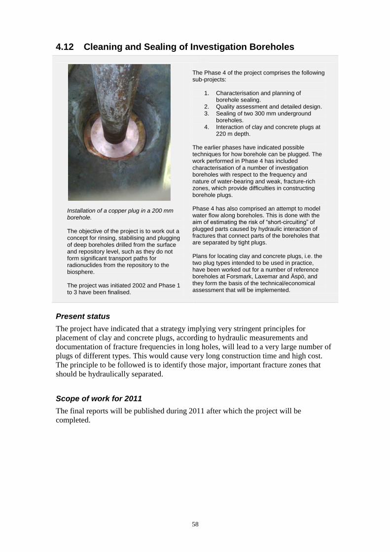
58
4.12 Cleaning and Sealing of Investigation Boreholes
Installation of a copper plug in a 200 mm borehole. The objective of the project is to work out a concept for rinsing, stabilising and plugging of deep boreholes drilled from the surface and repository level, such as they do not form significant transport paths for radionuclides from the repository to the biosphere. The project was initiated 2002 and Phase 1 to 3 have been finalised.
The Phase 4 of the project comprises the following sub-projects:
1. Characterisation and planning of borehole sealing.
2. Quality assessment and detailed design. 3. Sealing of two 300 mm underground
boreholes. 4. Interaction of clay and concrete plugs at
220 m depth. The earlier phases have indicated possible techniques for how borehole can be plugged. The work performed in Phase 4 has included characterisation of a number of investigation boreholes with respect to the frequency and nature of water-bearing and weak, fracture-rich zones, which provide difficulties in constructing borehole plugs. Phase 4 has also comprised an attempt to model water flow along boreholes. This is done with the aim of estimating the risk of “short-circuiting” of plugged parts caused by hydraulic interaction of fractures that connect parts of the boreholes that are separated by tight plugs. Plans for locating clay and concrete plugs, i.e. the two plug types intended to be used in practice, have been worked out for a number of reference boreholes at Forsmark, Laxemar and Äspö, and they form the basis of the technical/economical assessment that will be implemented.
Present status
The project have indicated that a strategy implying very stringent principles for
placement of clay and concrete plugs, according to hydraulic measurements and
documentation of fracture frequencies in long holes, will lead to a very large number of
plugs of different types. This would cause very long construction time and high cost.
The principle to be followed is to identify those major, important fracture zones that
should be hydraulically separated.
Scope of work for 2011
The final reports will be published during 2011 after which the project will be
completed.
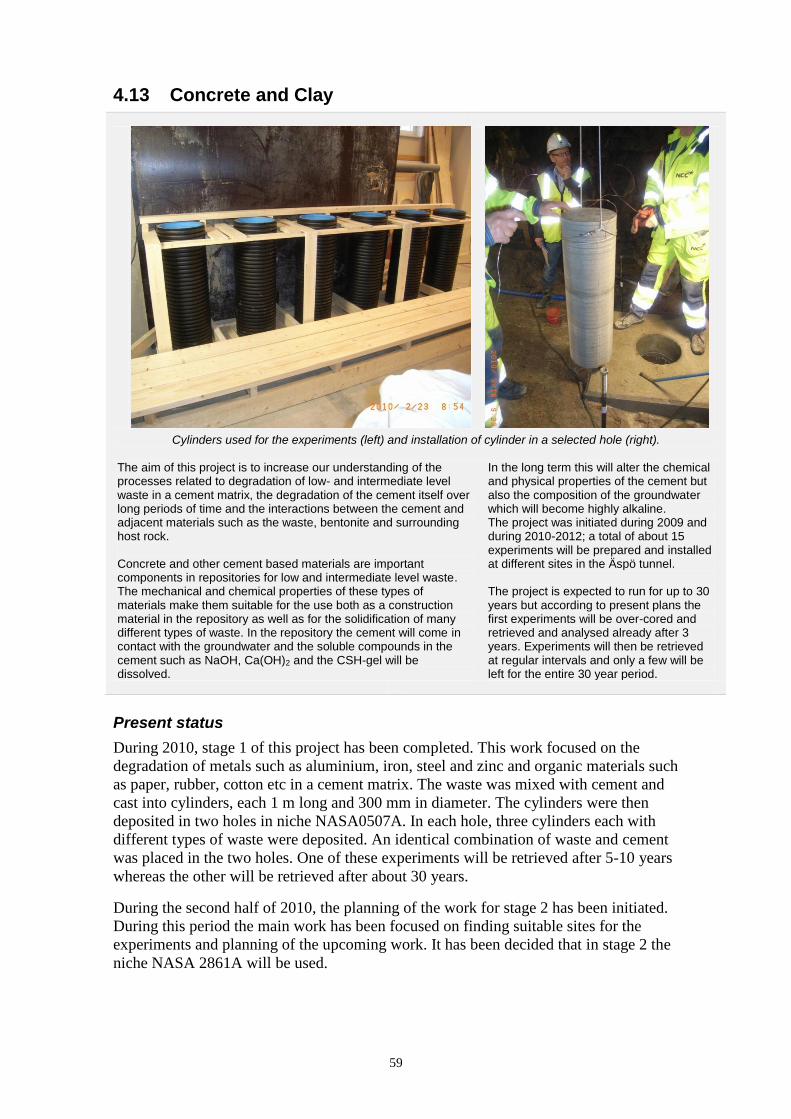
59
4.13 Concrete and Clay
Cylinders used for the experiments (left) and installation of cylinder in a selected hole (right).
The aim of this project is to increase our understanding of the processes related to degradation of low- and intermediate level waste in a cement matrix, the degradation of the cement itself over long periods of time and the interactions between the cement and adjacent materials such as the waste, bentonite and surrounding host rock. Concrete and other cement based materials are important components in repositories for low and intermediate level waste. The mechanical and chemical properties of these types of materials make them suitable for the use both as a construction material in the repository as well as for the solidification of many different types of waste. In the repository the cement will come in contact with the groundwater and the soluble compounds in the cement such as NaOH, Ca(OH)2 and the CSH-gel will be dissolved.
In the long term this will alter the chemical and physical properties of the cement but also the composition of the groundwater which will become highly alkaline. The project was initiated during 2009 and during 2010-2012; a total of about 15 experiments will be prepared and installed at different sites in the Äspö tunnel. The project is expected to run for up to 30 years but according to present plans the first experiments will be over-cored and retrieved and analysed already after 3 years. Experiments will then be retrieved at regular intervals and only a few will be left for the entire 30 year period.
Present status
During 2010, stage 1 of this project has been completed. This work focused on the
degradation of metals such as aluminium, iron, steel and zinc and organic materials such
as paper, rubber, cotton etc in a cement matrix. The waste was mixed with cement and
cast into cylinders, each 1 m long and 300 mm in diameter. The cylinders were then
deposited in two holes in niche NASA0507A. In each hole, three cylinders each with
different types of waste were deposited. An identical combination of waste and cement
was placed in the two holes. One of these experiments will be retrieved after 5-10 years
whereas the other will be retrieved after about 30 years.
During the second half of 2010, the planning of the work for stage 2 has been initiated.
During this period the main work has been focused on finding suitable sites for the
experiments and planning of the upcoming work. It has been decided that in stage 2 the
niche NASA 2861A will be used.

60
Scope of work for 2011
During early 2011 two pilot holes will be drilled on selected site NASA2861A.
Depending on the results from the characterisation programme, a choice of experiments
for this site will be made. Once the experiments have been selected the site will be
prepared and the concrete cylinders cast and deposited in the same manner as in stage 1.
It is expected that stage 2 will be completed during spring 2011.
Also during 2011 the planning of the final stage, stage 3, of this project will be initiated.
Stage 3 will include the remaining experiments and utilise a new tunnel not yet
available. It is currently expected that stage 3 will be completed during 2012 but this is
dependent on the progress of the work with the new tunnel.
4.14 Low-pH Programme
The purpose of this programme is to develop low-pH cementitious products that can be used in the final repository for spent nuclear fuel. These products would be used for sealing of fractures, grouting of rock bolts, rock support and concrete for plugs for the deposition tunnels. SKB has for many years had a close co-operation with Posiva (Finland) and Numo (Japan) in this field. The main focus of the low-pH programme during 2008 and 2009 has mainly been on developing formulas for low-pH concrete to be used for construction of the sealing plugs for the deposition tunnels. In 2009 new field tests with rock bolts and shotcrete for rock support was performed at Äspö.
Field test with low-pH shotcrete at Äspö HRL executed within the EC project ESDRED in 2006.
Present status
During 2009 SKB performed field test with low-pH grout for rock bolts at Äspö HRL.
In total, 20 bolts have been installed. These bolts will be monitored and overcored after
1, 2, 5 and 10 years for evaluation of the behaviour of the low-pH grout but also
corrosion of the rock bolts. The main activity during 2010 has been the preparation of
an official report of the work performed during 2009.
An international project for standardisation of pH measuring started mid 2008 as a joint
project with the following participating organisations: SKB, Posiva, Nagra, Enresa,
Numo and JAEA. The work within the pH-project has been ongoing during 2010 and
pH-measurements have been performed in nine laboratories in the six different
countries and the results have been presented in an interim report. “Real” samples of
low pH-products have also been prepared by four members of the consortium and pH-
measurements were done in the same laboratories as in the previous phase.
The preparation for overcoring of the first set of rock bolts has also been ongoing during
the year, as well as follows up of the corrosion experiments with carbon steel rock bolts
in low-pH concrete.

61
Scope of work for 2011
The work during 2011 will be limited to continue with following up the activities from
2009 with the rock bolts and rock support and preparing the official report. The report is
planned to be completed mid 2011. Overcoring of four bolts is planned during 2011.
The pH-measuring project will be finalised mid 2011.

62
4.15 Task Force on Engineered Barrier Systems
The second phase of The Task Force on Engineered Barrier Systems (EBS) started in 2010 and is a natural continuation of the modelling work in the first phase. The first phase included a number of THM (thermo-hydro-mechanical) tasks for modelling both well-defined laboratory tests and large scale field tests such as the two Canadian URL tests (Buffer Container Experiment and Isothermal Test) and the Canister Retrieval Test in Äspö HRL. In the first phase the Task Force was also enlarged to two groups, one treating the original THM issues and one group concentrating on Geochemical issues. The two Task Force groups have a common secretariat, but separate chairmen. The second phase of the Task Force includes so far the following tasks: THM:
1. Sensitivity analysis 2. Homogenisation 3. Task 8 (common with Task Force on
Modelling of Groundwater Flow and Transport of Solutes)
4. Prototype Repository
Geochemistry:
1. Salt diffusion in montmorillonite 2. Gypsum dissolution and sulphate diffusion
in montmorillonite 3. Calcium/sodium exchange of
montmorillonite in compacted state 4. Core infiltration of MX-80 bentonite with
artificial groundwater
The objectives of the Tasks are to: a) verify the capability to model THMC
processes in unsaturated as well as saturated bentonite buffer
b) refine codes that provide more accurate predictions in relation to the experimental data
c) develop the codes to 3D standard (long-term objective)
d) evaluate available conceptual material models.
Participating organisations in phase 2 are besides SKB at present BMWi (Germany), CRIEPI (Japan), Nagra (Switzerland), Posiva (Finland), NWMO (Canada) and RAWRA (Czech Republic). All together 10-15 modelling teams are foreseen to participate in phase 2.

63
Present status
Task Force THM/Gas
The first phase of the Task Force was finished in 2010 and included modelling of a
number of laboratory and fields tests as compiled in Table 4-2. Benchmark 1 (laboratory
tests) and benchmark 2.1 (the two URL tests) were finished and the modelling results
reported during 2009. The modelling of the Canister Retrieval Test (benchmark 2.2)
started in 2008 and was finished and reported in 2010.
Table 4-2 Modelled tests in the first phase of the Task Force on Engineered Barrier System.
Benchmark 1 – Laboratory tests
Task 1 – THM tests
1.1.1 Two constant volume tests on MX-80 (CEA)
1.1.2 Two constant volume tests on Febex bentonite – one with thermal gradient and one isothermal (Ciemat)
1.1.3 Constant external total pressure test with temperature gradient on Febex bentonite (UPC)
Task 2 – Gas migration tests
1.2.1 Constant external total pressure (BGS)
1.2.2 Constant volume (BGS)
Benchmark 2 – Large scale field tests
2.1 URL tests Buffer/Container Experiment and Isothermal Test (AECL)
2.2 Canister Retrieval Test in Äspö HRL (SKB)
Four new tasks for phase 2 of the Task Force have been presented in 2010:
Sensitivity analyses
The analyses refer to a base case definition, which is proposed to be a deposition hole
with KBS-3V geometry and MX-80 as buffer material. The base case will consist of
well defined hydro-mechanical boundary conditions with relevant canister power and
also include different stages of the repository life-time. The buffer, rock and canister
properties will be defined and thermal, hydraulic and mechanical results requested in
well defined positions. Then the influence of different conditions and parameter values
will be investigated with sensitivity analyses.
Homogenisation
This task mainly relates to homogenisation after loss of bentonite by mechanical or
chemical erosion but may also refer to homogenisation of initial gaps that are present
since the reference buffer and backfill will be made of pre-compacted blocks.
The background of this task is that bentonite has excellent swelling properties but the
homogenisation is not complete due to friction, hysteresis effects and anisotropic stress
distributions. The task is proposed to involve two phases. In the first phase a number of
benchmark laboratory tests will be modelled and used for checking/calibrating the
mechanical model. In the next phase one or two laboratory tests that simulate bentonite
lost in a deposition hole are planned to be performed and preceded by predictive
modelling.

64
The first phase includes three different swelling and homogenisation tests with simple
geometry:
One-dimensional swelling.
Swelling and closure of an axial-symmetric slot.
Swelling and closure of an axial-symmetric hole.
Task 8 The Task refers to a test made with the purpose to stimulate co-operation between the
two Task Forces (Engineered Barrier Systems and Groundwater Flow). This task is a
proposal to model a new field test named Brie (Bentonite Rock Interaction Experiment)
to be installed in Äspö HRL. The purpose of the test is to study and model the hydraulic
interaction between the rock and water unsaturated bentonite.
A task definition has been prepared and distributed. The task is divided into four
different sub-tasks. Sub-task 8a is a generic scoping calculation exercise with a 2D
axisymmetric geometry with a horizontal intersecting fracture. Sub-task 8b is also a
scoping calculation, but in 3D with more site-specific data from the Taso-tunnel
regarding geometry and fractures. In the distributed task definitions, this also includes
some sensitivity analyses regarding material properties, boundary conditions and
fracture location. When results from the characterisation of the Taso-tunnel are
available, sub-task 8c will be a blind prediction of the inflow into the central borehole.
Finally, sub-task 8d will be a blind prediction of the bentonite hydration.
Prototype Repository
The motivations to model the Prototype Repository are the following:
It has identical geometry with the Canister Retrieval Test but natural hydraulic
interaction with the rock.
There is extensive instrumentation.
The test includes interaction buffer/backfill.
A part of the test will be excavated just in time to be included in phase 2.
The modelling will partly be a true prediction.
It can be a joint task with the Task Force on Modelling of Groundwater Flow
and Transport of Solutes.
A task definition has been produced and distributed.
Task Force Geochemistry
Apart from the project meetings in May and November 2010, the geochemical part of
the EBS Task Force also met at an intermediate workshop held in Speyer, Germany,
30th
of June – 1st of July, 2010. During the year, the University of Bern (Nagra),
Universidad Autonoma de Madrid (Nagra), Clay Technology (SKB), Amphos21 (SKB),
VTT (Posiva), Grüner (Posiva), Czech Nuclear Research Institute (Rawra) have
contributed to the activity.
Modelling work
Three experimental data sets on montmorillonite systems have so far been presented to
use for benchmark calculations: (1) salt diffusion, (2) gypsum dissolution and sulphate
diffusion and (3) calcium/sodium exchange of montmorillonite in compacted state.
During the year, Clay Technology has presented (continued) work performed on both
data set (1) and (3). Focus has been on comparison between applying the ion-
65
equilibrium or the multi-porosity approach to compacted bentonite. Amphos21 have
presented modelling of the saturation phase of the A2 parcel of the Long term test of
buffer material at Äspö HRL. The model involves gaseous, liquid and solid phases,
temperature gradients, and both advective and diffusive transport. The main focus of the
modelling was on the redistributed sulphate in the hot parts of the A2 parcel, as well as
on the chloride inventory. Modelling of Äspö field test experiments will be further
addressed in the second phase of the Task Force.
Universidad Autonoma de Madrid has presented modelling of the core infiltration test
performed on MX-80 bentonite at university of Bern. The experiment has been
modelled using both Phreeqc and Crunchflow, utilising the multi porosity approach
with DDL-theory features. Results from the core infiltration test will soon be made
available within the Task Force as a benchmark data set.
The Czech Nuclear Research Institute has presented porewater calculations made on
MX-80 and Rokle bentonite using Phreeqc.
An extension of the ion equilibrium approach to pressure and water flow responses due
to externally applied water pressure gradients were presented by Clay Technology. It
was shown that central concepts such as Darcy‟s law for water flow and the effective
stress equation can be derived for compacted bentonite by considering only the water
chemical potential. The theory was successfully applied to the UniBern core infiltration
test and to Clay Technology water flow experiments showing non-linear flow and
pressure response. This is an attempt to bridge the two Task Force issues.
Clay Technology presented further molecular dynamic simulations of the
montmorillonite/water system which illuminates the concepts of Donnan equilibrium,
friction and colloidal coagulation due to ion-ion correlation effects in Ca-
montmorillonite.
Code development
The creator of the reactive transport code Crunchflow, Carl Steefel, presented the newly
implemented diffuse double layer feature of Crunchflow at the Speyer workshop. A
short hands-on demonstration of how to work with the code was also given.
Presentation of additional experimental work
The analysis of cations and anions in the first parcel of the Äspö HRL field test
Alternative Buffer Materials (ABM) was presented and compared to earlier results of
the A2 parcel from Long term test of buffer material. Two distinctive features were
observed in the ABM parcel: 1) Chloride concentrations were significantly lower than
in the groundwater and were negatively correlated with bentonite quality and density.
These observations are in complete agreement with the theory of Donnan equilibrium.
2) Major internal diffusion was observed of the charge compensating cations,
suggesting that interlayer diffusivity is the major transport mechanism.
UniBern presented initial results from a second core infiltration test, performed at
~140°C.
Czech Nuclear Research Institute presented mineralogical analyses of the Rockle
bentonite. The data is proposed as a benchmark data set.

66
Scope of work for 2011
Task Force THM/Gas
For 2011 the following work is planned:
Sensitivity Analyses: Prepare a task definition and start the modelling of this
task.
Homogenisation: Prepare a task definition and start the modelling work.
Task 8: Continued modelling in sub-tasks 8a and 8b and start of sub-task 8c.
Prototype Repository: The first predictive modelling results are requested before
the next meeting in the beginning of June. They will be used for comparison
with results of the excavation investigations which are due to be available after
summer.
Two task force meetings are planned for 2010.
Task Force Geochemistry
For 2011 the following work is planned:
Multi-Author Report on first phase activities.
Focus on calculations based on distributed experimental data sets (ion diffusion,
gypsum dissolution, ion exchange, core infiltration test) for all modelling
groups.
Continuation of molecular dynamics modelling.
Continued development of codes (e.g. possible implementation of ion
equilibrium concepts in Crunchflow).
Further emphasis on coupling between “chemistry” and hydraulics/mechanics
(HMC).
Supporting laboratory tests performed at University of Bern and at Clay
Technology.

67
5 Mechanical- and system engineering
5.1 General
At Äspö HRL and the Canister Laboratory in Oskarshamn, techniques for the final
disposal of spent nuclear fuel are under development. Both well-tried existing
technologies and new technologies will be used. As far as possible standard objects,
modified and adapted to the activity, will be used. Where no standard equipment is
available new objects must be developed.
5.2 Technical Development at Äspö HRL
Backfilling equipment Lifting tool for buffer emplacement
Deposition machine Multipurpose vehicle
The technical systems, machines and vehicles that need to be developed for the future final repository have been identified in an inventory project. A total of 175 different products and components known today are to be developed. Preliminary plans were made on when the production of machines must begin and when they should be completed. In addition, assessment could be made whether production of prototypes are necessary. The number of objects and affiliated information is due to change since the specifications are working documents. The development of a model for costs has been included in the work. Several projects within mechanical- and system engineering are ongoing and the activities in some of the different projects are described in the text below.

68
5.2.1 Deposition machine
Present status
Full scale tests with fully automatic operation are in progress. The tests are performed to
collect data and to evaluate the reliability and availability of the objects. Also the
service requirements during continuous operation are tested.
The trial run commenced in the beginning of 2010 and recorded test runs will last from
end of 2010 until about 1,000 depositions have been performed. A product information
leaflet on the deposition machine has been produced. Fine adjustment of the software
has continued during 2010 and detected errors are corrected. A remote connection is
established, and Navitec Systems are now using the remote connection for maintenance
and fine adjustment of the software. An uninterruptible power supply (UPS) to the
screens is installed in the driver‟s cabin. A test plan for the durability tests to be
performed during 2011 has been developed.
Scope of work for 2011
The full scale tests with the deposition machine will continue during the year. A
maximum of one thousand complete depositions will be performed. A test report will be
completed during 2012.
5.2.2 Equipment for backfilling
Present status
The project includes design and tests of the backfilling equipment. A computer
simulation showed that a robot has the capacity to place 220 tons of backfilling blocks
per day. This capacity is assumed in the logistic studies for the backfilling of deposition
tunnels in the final repository facility.
Scope of work for 2011
Future work includes manufacturing and testing of the prototype equipment, consisting
of a mobile platform, industrial robot and a vacuum tool. During 2011 the robot will be
manufactured and delivered. A rack mounted laser to check and measure the result of
backfilling with the robot has to be purchased. The multipurpose vehicle will be used as
platform for the robot. Tests will be performed in the Bentonite Laboratory and at the
level -420 m at Äspö HRL.
5.2.3 Buffer emplacement
Present status
The aim of this project is to find out whether the buffer can be placed in the deposition
holes with the required degree of precision. The buffer consists of blocks and rings.
The steering gear of the tool for lift and location of the buffer was completed during
2010. The tool works with vacuum to hold the buffer and has shown good function in
laboratory tests.
69
Scope of work for 2011
Before final tests minor adjustments on the crane have to be made. The buffer rings
used for tests are too porous and easily damaged. No vacuum was achieved on the
damaged rings. The rings are being repaired for future use. Uncertainties of the
condition of the rings result in ordering of the new rings.
A test programme is drawn up, as well as a plan and instructions for the execution of
quantity and endurance tests. The test programme describes the design, number,
sequence and documentation of necessary lifting equipment. The tests will start shortly.
5.2.4 Multipurpose vehicle
Present status
SKB needs continuous heavy load transports in the ramp at the Äspö HRL. To have
these transports executed, a Multi Purpose Vehicle (MPV) for heavy transports was
ordered in November 2010.
Scope of work for 2011
The vehicle will be delivered in March 2011. During 2011 the MPV will transport e.g.
material from the excavation of the Prototype repository. It will be used as a platform
during technology development of various systems e.g. development of the mission
control system and development of equipment for backfilling. It will also act as a
prototype for the future ramp vehicle for the deep repository.
5.2.5 Logistics studies
Present status
The main objective of the logistics studies for the final repository for spent fuel is to
simulate all activities at the repository during the operational phase. The studies include
rock excavation, emplacement of buffer, canister and backfill, sealing of the deposition
tunnel with a concrete plug. These logistics studies must be done in steps over a period
of 3 to 4 years as needed information is not available at present.
A demonstration project was completed in June 2010. The purpose of this project was to
find out if suitable software is available and if it is a practical way to carry out this type
of simulations. The results of the project were used for internal information and as
decision basis for continued logistics studies. Planning and preparatory work for
continuation of the project has proceeded since June, after the results from the
feasibility study were presented to the client.
The aim of the logistic studies is to be a part of the decision making process for
operation and control of all activities of the final repository and also provide
information needed for detailed design of systems and equipment with respect to:
Time needed for various activities.
Bottlenecks and sensibility for disturbances.
Layout and design of different parts of the facility.
Design requirements for technical systems.
Determine the need of different machines/vehicles and required capacity.

70
Form a model for control, supervision and follow up of operation and
maintenance.
Organisation structure for the final repository including staffing.
Costs.
Other logistics studies of reception, transportation and deposition of decommissioning
waste and operational waste at SFR (Final Repository for Short-lived Radioactive
Waste) from year 2020 and onwards are done within the project for extension of SFR.
Scope of work for 2011
The required software will be purchased during 2011. Further developing work with
simulation of the final repository is planned to continue between January and June. The
model includes the skip building, the skip hall, the reloading station and 4 to 8
deposition tunnels. In addition, the development of a SFR model will start.
5.2.6 Mission control system
Present status
Within this project, a prototype of a comprehensive automatic system for the
management and control of transport and production logistics for the final repository
will be developed. Preparatory work has been made during 2010 and formally the
project started in October 2010. The decision to develop a mission control system
establishes a working method for the final repository that facilitates the use of
automated vehicles.
Scope of work for 2011
Definition of properties and program structure will be finished during the first months in
2011. The mission control system and a related data base will be developed during 2011
and the test of the system will start in 2012.
5.2.7 Transport system for buffer and backfill material
Present status
A feasibility study to find a solution for transport of buffer and backfill material has
been carried out during 2010. The study has included the transport of material from the
production premises to the equipment that places the buffer in the deposition hole and
that installs the backfill and the pellets. The feasibility study has determined a concept,
which equipment to be used and a preliminary analysis has been made regarding human
factors. An internal report of the feasibility study has been produced.
Scope of work for 2011
Production of a project plan, a consequence analysis and a project directive are ongoing.
The purpose is to increase the level of detail from the feasibility study and work out a
requirement specification for the included equipment. However, during 2011 only
limited parts of the project will be prioritised, in order to let the project give necessary

71
input to other projects in progress: the logistics studies, the mission control system and
the buffer emplacement. Those projects will have increased attention during 2012.
The final target of the project is to deliver an autonomous and remotely operated
transport system for buffer and backfill material from the production premises to the
deposition tunnels.
5.2.8 Drilling Machine for Deposition Holes
Artist impression of the drilling machine for deposition holes with preliminary dimensions.
For the drilling of the deposition holes for various projects, SKB has used a modified TMB machine. In total SKB has drilled 17 deposition holes at Äspö HRL /Andersson and Johansson 2002/. A “state of the art” investigation of available technologies was performed during 2006 and the conclusion was that the push reaming technique would be the method that could meet the stringent requirement on the deposition hole and still have high production rate required for the final repository. This technology has also been tested in Finland for drilling of three deposition holes in the research tunnel at Olkiluoto /Autio 1997/. The same technology has also been used for the excavation of the two KBS-3H deposition tunnels at the -220 m level in Äspö HRL.
Present status
The requirements for the deposition holes are very stringent as well as production rate
and costs for the drilling of the deposition holes. A feasibility study has been performed
of a self propelled drilling machine using the push reaming technique. The feasibility
study was completed late 2008.
During 2010 Posiva decided to develop and manufacture a drilling machine using the
push reaming technique. This machine is expected to be ready for testing in Onkalo
during 2011. SKB is following the work at Posiva but has not been involved in the
development of the drilling machine.
Scope of work for 2011
During 2011, SKB will follow up the work that Posiva has done as well as the coming
results from the tests of the drilling machine in Onkalo. SKB do not need new
deposition holes at present at Äspö HRL.

72
73
6 Äspö facility
6.1 General
The Äspö facility comprises the Äspö Hard Rock Laboratory and the Bentonite
Laboratory, the later taken into operation in 2007. The Bentonite Laboratory
complements the underground Hard Rock Laboratory and enables full-scale
experiments under controlled conditions making it possible to vary experimental
conditions and to simulate different environments.
During 2010 the Äspö Hard Rock Laboratory has been through an organisation change
and the development of the Äspö facility is continuous ongoing, for example with the
building of a new geotechnical laboratory and extension of the tunnel.
The Repository Technology unit is organised in four operative groups and one
administrative staff function:
Geotechnical barriers and rock engineering (TDG), responsible for the
development, testing and demonstration of techniques for installation of buffer,
backfill and plugs in deposition tunnels, backfilling of the final repository and
plugging of investigation boreholes.
Mechanical- and system engineering (TDM), responsible for the development,
testing and demonstration of equipment, machines and vehicles needed in the
final repository.
Project and experimental service (TDP), responsible for the co-ordination of
projects undertaken at the Äspö HRL, providing services (administration,
design, installations, measurements, monitoring systems etc.) to the experiments.
Facility operation (TDD), responsible for the operation and maintenance of the
Äspö HRL offices, workshops and underground facilities and for development,
operation and maintenance of supervision systems.
Administration, quality and planning (TDA), responsible for planning, reporting,
QA, budgeting, environmental co-ordination and administration. The staffing of
the Äspö reception and the SKB switchboard are also included in the function.
Earlier were also Public relations and visitors group, TDI, a part of the Repository
Technology unit. However the group were transferred to the reorganised
Communications department within SKB in May 2010 and is now named
Communication Oskarshamn. The group and its personnel are, however, still located at
Äspö HRL and have a continuously close co-operation with the facility and the daily
coordination of underground activities.
Each major research and development task carried out in Äspö HRL is organised as a
project led by a project manager reporting to the client organisation. Each project
manager is assisted by an on-site co-ordinator with responsibility for co-ordination and
execution of project tasks at the Äspö HRL. The staff at the site office provides
technical and administrative service to the projects and maintains the database and
expertise on results obtained at the Äspö HRL.
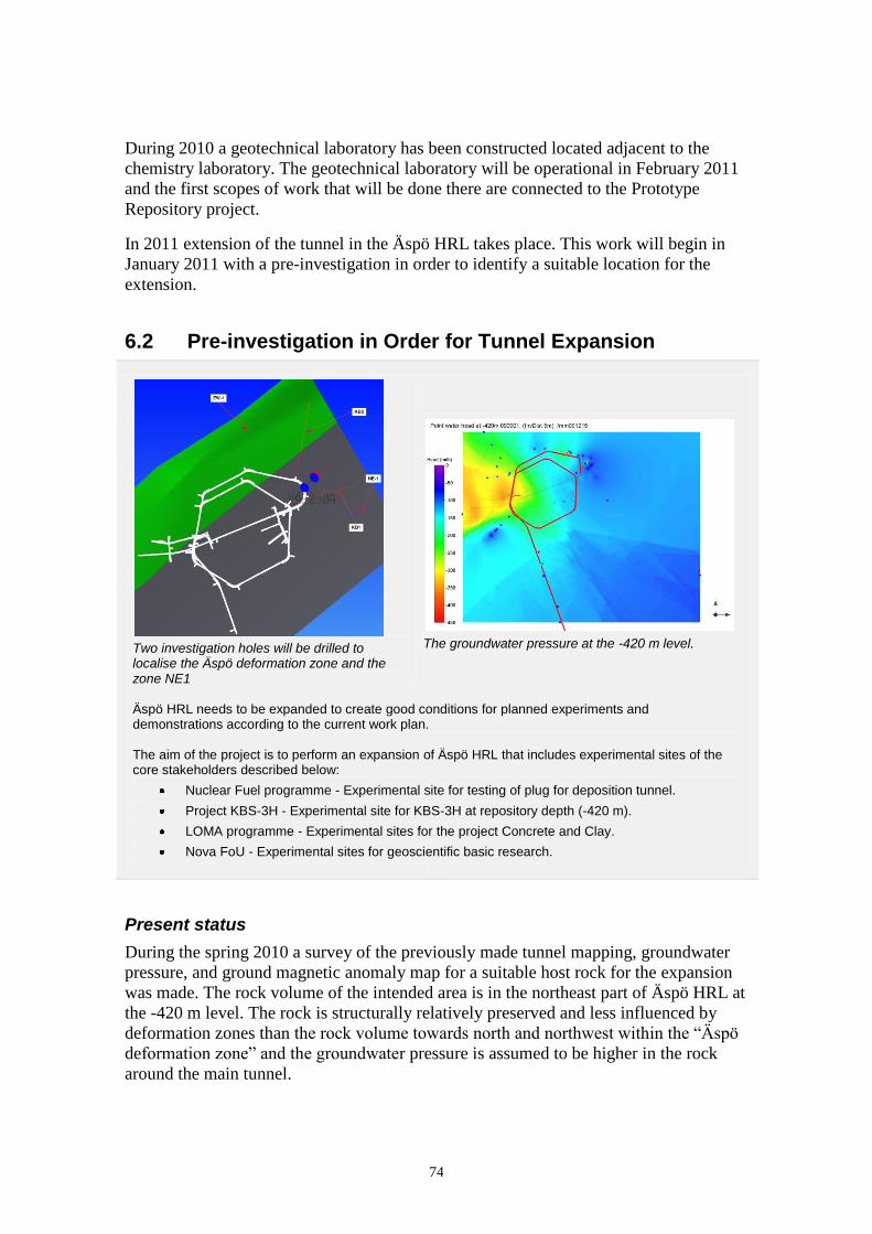
74
During 2010 a geotechnical laboratory has been constructed located adjacent to the
chemistry laboratory. The geotechnical laboratory will be operational in February 2011
and the first scopes of work that will be done there are connected to the Prototype
Repository project.
In 2011 extension of the tunnel in the Äspö HRL takes place. This work will begin in
January 2011 with a pre-investigation in order to identify a suitable location for the
extension.
6.2 Pre-investigation in Order for Tunnel Expansion
Two investigation holes will be drilled to localise the Äspö deformation zone and the zone NE1
The groundwater pressure at the -420 m level.
Äspö HRL needs to be expanded to create good conditions for planned experiments and demonstrations according to the current work plan. The aim of the project is to perform an expansion of Äspö HRL that includes experimental sites of the core stakeholders described below:
Nuclear Fuel programme - Experimental site for testing of plug for deposition tunnel.
Project KBS-3H - Experimental site for KBS-3H at repository depth (-420 m).
LOMA programme - Experimental sites for the project Concrete and Clay.
Nova FoU - Experimental sites for geoscientific basic research.
Present status
During the spring 2010 a survey of the previously made tunnel mapping, groundwater
pressure, and ground magnetic anomaly map for a suitable host rock for the expansion
was made. The rock volume of the intended area is in the northeast part of Äspö HRL at
the -420 m level. The rock is structurally relatively preserved and less influenced by
deformation zones than the rock volume towards north and northwest within the “Äspö
deformation zone” and the groundwater pressure is assumed to be higher in the rock
around the main tunnel.
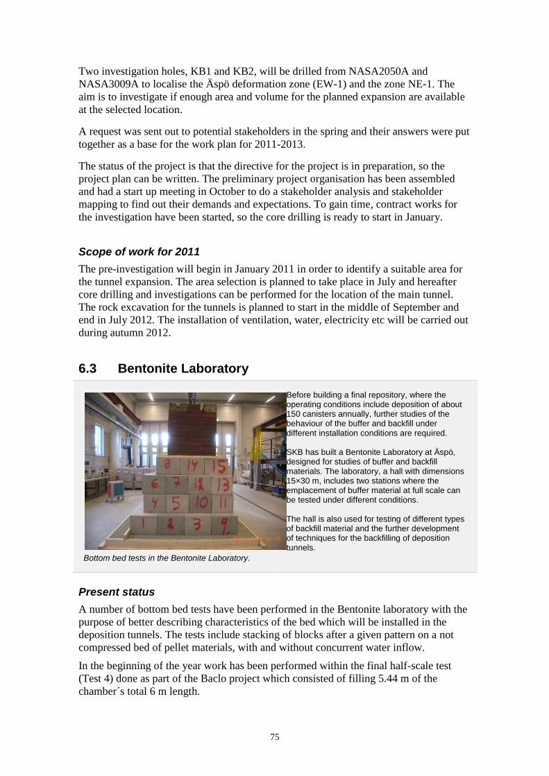
75
Two investigation holes, KB1 and KB2, will be drilled from NASA2050A and
NASA3009A to localise the Äspö deformation zone (EW-1) and the zone NE-1. The
aim is to investigate if enough area and volume for the planned expansion are available
at the selected location.
A request was sent out to potential stakeholders in the spring and their answers were put
together as a base for the work plan for 2011-2013.
The status of the project is that the directive for the project is in preparation, so the
project plan can be written. The preliminary project organisation has been assembled
and had a start up meeting in October to do a stakeholder analysis and stakeholder
mapping to find out their demands and expectations. To gain time, contract works for
the investigation have been started, so the core drilling is ready to start in January.
Scope of work for 2011
The pre-investigation will begin in January 2011 in order to identify a suitable area for
the tunnel expansion. The area selection is planned to take place in July and hereafter
core drilling and investigations can be performed for the location of the main tunnel.
The rock excavation for the tunnels is planned to start in the middle of September and
end in July 2012. The installation of ventilation, water, electricity etc will be carried out
during autumn 2012.
6.3 Bentonite Laboratory
Bottom bed tests in the Bentonite Laboratory.
Before building a final repository, where the operating conditions include deposition of about 150 canisters annually, further studies of the behaviour of the buffer and backfill under different installation conditions are required. SKB has built a Bentonite Laboratory at Äspö, designed for studies of buffer and backfill materials. The laboratory, a hall with dimensions 15×30 m, includes two stations where the emplacement of buffer material at full scale can be tested under different conditions. The hall is also used for testing of different types of backfill material and the further development of techniques for the backfilling of deposition tunnels.
Present status
A number of bottom bed tests have been performed in the Bentonite laboratory with the
purpose of better describing characteristics of the bed which will be installed in the
deposition tunnels. The tests include stacking of blocks after a given pattern on a not
compressed bed of pellet materials, with and without concurrent water inflow.
In the beginning of the year work has been performed within the final half-scale test
(Test 4) done as part of the Baclo project which consisted of filling 5.44 m of the
chamber´s total 6 m length.

76
This allowed for two, fracture-isolated sections to be constructed within the same
assembly and allowed also for evaluation of how a series of isolated tunnel sections will
interact as water influx to the tunnel progresses, see Section 6.3.1.
Scope of work for 2011
During 2011, additional tests will be performed of the bottom bed which will be
installed in the deposition tunnels. The tests will include stacking of blocks on different
bed materials, with and without concurrent water inflow. Bed stability during water
inflow will also be tested. The results will be used to describe the prerequisites for block
installation.
Work concerning development of techniques for backfilling will continue during 2011.
The purpose is to verify the results in small and larger scale tests. The installation
technique and pellet filling degree in realistic environment will be tested in order to be
able to give recommendations on installation equipment and to gain information on how
the parameters are influenced during the installation.

77
6.3.1 Impact of Water inflow on backfill
Migration of the water content in the three layers in test with an inflow rate of 0.1 L/min. Photo of upper surface with meandering water expelled from the steep channel. The objective of the project is to investigate the impact of inflow from the rock on the constitution and properties of the pellet backfill in deposition tunnels. It is preceded by tests on different scales with similar intentions but without the present objective of identifying the detailed, actual process of water uptake of the pellet fill, and of determining realistic multi-point inflows corresponding to real rock structure. The project comprises the following sub-projects: Sub-project 1 - It is focusing on the mechanisms that control migration and distribution of water entering
pellet fills from inflow spots in the rock. The tests will be made on blasted rock slabs for identifying how water is taken up from “dry” and “wet” rock by pellet fills and flows along the rock/pellet contact. Sub-project 2 - The first part includes determination of inflow into pellet fill in ”1/2-scale” tests using steel
tunnels similar to earlier Baclo-experiments but with water inflow from coupled inflow spots simulating water-bearing fractures. The selection of the location of the spots is based on actual fracture mappings of water-bearing fractures in blasted tunnels at the Äspö HRL.
The second part includes a test series in which “wetted pellets” is placed in contact with “dry pellets” for simulating quick water saturation of parts of the tunnel backfill separated by less wet pellet fill into which water flows at a late stage. The major objective of the experiments in these tests is to find out what the critical inflow rate is in order to estimate what the backfilling rate is in meters per day without meeting significant problems with softening of placed backfill. A second purpose is to determine the conditions for creation of piping in partly water-saturated pellet fill.
Present status
The project was planned to give information on how water entering a KBS-3V tunnel
from water-bearing rock fractures enters the pellet backfill. A primary question was if
transport of water from a fracture takes place along the contact between the pellet
backfill and the rock or if it has the form of penetration into the interior of the pellet
Photo: A Hedin

78
backfill in the normal direction. A second question was if the mechanisms of water
transport through a pellet fill from an inflow spot can change in the course of
permeation e.g. from relatively uniform migration to concentrated flow leading to
channelling. Both issues were investigated experimentally leading to conceptual models
of water migration in fillings of smectite-rich pellets.
Scope of work for 2011
The results from the investigations will be published in final reports during 2011 after
which the project will be completed.

79
6.4 Facility Operation
The main goal for the operation is to provide a safe and environmentally sound facility for everybody working or visiting Äspö. This includes preventative and remedial maintenance in order to ensure that all systems such as drainage, electrical power, ventilation, alarm and communications have a high degree of availability.
Present status
The operation of facility has been stable during 2010, and the underground facility was
only closed for planned stops. Rock maintenance has been carried out as planned and
the new work platform which contractors use is working as planned. The maintenance
work is both faster and safer. However, the rock support measures were considerably
more expensive than projected with shotcrete, rock bolts and verifications of previous
reinforcement.
A work to restore and asphalt the road in the TASS- and TASQ-tunnels after completing
experiments has been performed. In addition, three new measure banks have been built
in the TASQ-tunnel.
Upgrading the elevator machine has been done. A new security computer has been
installed and the unit has been replaced by a new and more modern model. To maintain
security, the tunnel was closed down while work was going on and only emergency
work was carried out. The exchange of cable ladders in the elevator shaft to a stainless
steel model has been made between -340 m and -220 m level during the summer.
Before dismantling of the outer section of the Prototype repository, the premises are
rebuilt to be able to perform the analysis of bentonite samples. Redevelopment of the
current warm storage to a geotechnical laboratory is in progress. Floor surfaces in the
drill core archive have been reduced and in the remaining floor space a new goods
reception has been built.
The work with the long planned sewer to OKG´s treatment plant and the new water
plant started during the autumn. The work should be finished by the end of the year, but
has been delayed.

80
Scope of work for 2011
During 2011, maintenance and other daily work continue as usual. Beyond this he
following work is planned:
The complete sewerage and water system will be tuned and process images and
alarms will be connected into the overall monitoring system.
The construction of the new geotechnical laboratory will be completed and a
final inspection will be made.
Upgrading of the elevator machine control system will continue.
Access Control System in the new office of Polstjärnan will be upgraded to the
same system as other facilities.
Prior to the expansion of the facility under ground, the group will participate in
the development of technical systems for drainage, electricity, ventilation and
water etc. In order to purify drainage water during the expansion, water
purification equipment will be bought or rented.
A place to wash vehicles will be built with an oil separator and a simple roof.
An upgrade of the software to the object monitoring system Alfagate will be
made and supplemented with new hardware.
The IT-department will move existing servers to the headquarters and current
server room will be moved from Äspö HRL. Local operating servers will be
placed in a secure room at the facility.
An energy analysis will be carried out in Äspö HRL during 2011. The analysis
will serve as the basis for savings during the year 2012.
The fire alarm system of the facility will be updated with new fire detective
stories and new software.
A new site for waste disposal will be completed.

81
6.5 Communication Oskarshamn
The main goal for the communication unit in Oskarshamn is to create public acceptance for SKB, which is done in co-operation with other departments at SKB. The goal will be achieved by presenting information about SKB, our facilities and the RD&D work which is carried out at for example Äspö.
Furthermore, the unit is responsible for the visitor services at the central interim storage (Clab) and the Canister Laboratory and for taking care of and administrating all visitors to SKB´s facilities. The unit has the responsibility for SKB´s exhibitions, for school information in Oskarshamn as well as in Östhammar, the magazine Lagerbladet etcetera.
Present status
During 2010 a new organisation has been implemented. The visitor service is still a
large and important part of the tasks carried out by the unit in close co-operation with
the Äspö facility and the daily co-ordination of underground activities.
During the year 2010 the facilities in Oskarshamn (Äspö facility, Clab and the Canister
Laboratory) were visited by 11,340 visitors. The total number of visitors to all SKB
facilities in Oskarshamn and Forsmark was 18,374 persons. The visitors represented
general public, municipalities where SKB performed site investigations, teachers,
students, professionals, politicians, journalists and visitors from foreign countries.
The unit also went to schools and high-schools within the municipality of Oskarshamn
and met approximately 1,400 students and teachers. The unit have also met 800 students
in the municipality of Östhammar.
82
Three to four times a year, a news letter is sent out to the teachers. All students in 9th
grade in Oskarshamn are offered a visit to Äspö HRL and the Canister Laboratory and
all students in the 3rd
grade in high-school are offered a visit to Clab.
During 2010 the unit published three issues of the magazine Lagerbladet which is sent
out to all the households in the municipality and to subscribers all over Sweden. Anyone
can subscribe for free. The goal with Lagerbladet is to tell the public about SKB´s work
in a way that is not too technical and also to show the persons behind SKB.
The unit has arranged the Geological Day and Researcher´s Night during 2010. The
Researcher´s Night was arranged at Äspö on the 24th
of September. The theme was
“Machines in the final repository”. The Geological Day was arranged for students the
10th
of September and for the public the 11th
of September. The public went for a
geological walk through Oskarshamn with about 60 participants. In November 80
competitors participated in the Äspö Running Competition. On December 4th
an event
was held at Äspö as a contribution to “Oskarshamn in Light”. The event consisted of a
light and music show down the laboratory. 50 people took the chance to visit Äspö and
at the same time see the show.
Planned special events for 2011
During 2011 plans are to show the facilities to visitors according to SKB´s visitor
strategy. Underground tours for the public are planned to take place during the summer
and on selected Saturdays during the year. Other planned activities are:
School information
Planning for the ordinary activities as well as for arranging study trips to SKB´s
facilities.
Arrange the Geology Day and Researcher´s Night in September and Äspö
Running Competition in December.
Äspö Hard Rock Laboratory celebrates 25 years during 2011 and this will be
acknowledged in different ways.
The magazine “Lagerbladet” is planned with three issues during 2011.
Furthermore the unit is involved in a number of other communication tasks such as the
planning of a new exhibition at the project office for the final repository in Forsmark,
research communication, crisis communication, web production etc.

83
7 Open research and technical development platform, Nova FoU
7.1 General
Äspö Hard Rock Laboratory is a world unique underground research laboratory which
is now open for more general research. Nova FoU (www.novafou.se) is the organisation
which implements this policy and facilitates external access for research and
development projects to the SKB facilities in Oskarshamn (see Figure 7-1).
Nova FoU is a joint research and development platform at Nova Centre for University
Studies and R&D supported by SKB and the municipality of Oskarshamn. Nova FoU
provides access to the Hard Rock Laboratory and the Bentonite Laboratory at Äspö and
the Canister laboratory in Oskarshamn.
Figure 7-1. Nova FoU provides access to the SKB facilities and data for universities
and companies for general research and technical development. Nuclear waste
management research is handled by SKB.

84
The aim with the research and development projects through Nova FoU is to create long
term spin-offs and business effects beneficial to the region. Nova FoU supports new and
innovative research, for example environmental studies, where the extensive SKB data
set from geological, hydrogeological, hydrogeochemical and ecological investigations
and modelling can be used (Figure 7-2).
Figure 7-2. The Äspö and Laxemar areas have been studied in terms of geology,
hydrogeology, hydrogeochemistry and ecology. This information can be used for a
number of purposes, for example to describe the water cycle and hydrogeochemical
processes in 3D.
The data can be used e.g. for assessing the consequences of natural resource
management and pollution risks. The data and models can be used to estimate exposure
both at individual and population levels. Development of monitoring and analytical
systems can be performed relating to the management of various renewable natural
resources in, for instance, agriculture, fisheries, forests and groundwater. Studies which
give a better knowledge concerning pollution problems coupled to toxicological and
epidemiological issues are possible. Technology, innovations and spin-off effects at pre-
market stages are of special interest.
Possible scientific and technical work at Äspö HRL is:
Scientific work:
How life is formed in underground conditions.
Evolution of life where sunlight and oxygen are absent.
How the deep parts of the hydrological cycle work.
Interaction between deep and shallow groundwater systems.

85
The nature of complex hydrogeochemistry.
The character of water totally unaffected by man (deep brine).
Development of fracture fillings over geological time.
Environmental changes revealed by fracture minerals and groundwater.
Generation of fracture networks in three dimensional spaces.
Technical development:
Visualisation, simulation and animation of phenomena in natural science.
New sampling, measuring and orientation devices for underground work.
Material and technical development in corrosive and high pressure underground
environment.
Scope of work for 2011
The overall scope of work for the Nova FoU research platform for year 2011 is:
Continue to market the platform by inviting/visiting researchers and decision
makers to inform about research possibilities through Nova FoU.
Develop the platform by strategic support of projects and investments in
sampling equipment, analytical instruments, tunnel facilities etc.
Continue the strategic check of new research possibilities and focuses suitable
for the Nova FoU platform.
Improve the project support and follow up routines of the ongoing projects to
enhance the spin-off handling.
7.2 Nova Research and Development Projects
The ongoing research and development projects within Nova FoU and the project
owners are:
Lanthanoids in bedrock fractures (Linnaeus University).
Fluorine in surface and ground waters (Linnaeus University).
Modelling of groundwater chemistry (Linnaeus University).
Geobiology of microbial mats in the Äspö tunnel (University of Göttingen).
Coastal modelling (Royal Institute of Technology, KTH).
3D localisation system of persons, the Alfagate project (NeoSys AB).
Integrated fire protection, the Safesite project (NeoSys AB).
Utilisation of waste energy, the EoS project (Municipality of Oskarshamn).
Detailed fracture mineral investigations (Linnaeus University).
Expert group for the harbour remediation project in Oskarshamn (Municipality
of Oskarshamn).
Hydrochemical interaction between a tunnel and its surroundings – development
of prediction models (Chalmers University of Technology).
The status of the projects and the scope of work for 2011 are described in the sections
below.

86
7.2.1 Lanthanoids in bedrock fractures
Present status
The aim of the project is to characterise and describe the variability in concentrations
and fractionation patterns of lanthanoids in fracture minerals (primarily calcites) and
groundwaters in Proterozoic bedrock.
The status of the project is that: (1) concentrations and fractionation patterns of
lanthanoids in both calcites and groundwaters have been statistically analysed and
interpreted, (2) the abundance and fractionation of lanthanoids in the groundwaters have
been compared with results of Multivariate Mixing and Mass balance (M3) modelling,
and (3) the relationship between lanthanoid concentrations and drilling-water % in
groundwater samples have been studied.
Figure 7-3. Scatterplot of drilling-water percentage and lanthanoid concentrations in
groundwater.
The major results are as follows. There was no significant correlation between drilling-
water content and lanthanoid concentrations (Figure 7-3), which is a good starting point
for further statistical analyses and interpretation of the behaviour of the lanthanoids. The
calcites show overall a strong relative enrichment of the light lanthanoids, which also is
to be expected from partition coefficients obtained in other previous laboratory
experiments. The extent to which the light lanthanoids are enriched however varies
substantially, and in some cases even the heavy lanthanoids are just as high as the light
ones. It seems that a large part of the fractionation in the calcites can be explained by
the fractionation of lanthanoids existing in the deep groundwaters (only current-day data
exists) and partitioning into the calcites according to existing partition coefficients. This
will increase the understanding of the interaction of lanthanoids (and indirectly
actinoids) in groundwater and fracture minerals in crystalline bedrock.
The spin-off effects from the project are so far mainly that the results can be used as a
reference and starting point for other detailed lanthanoid and trace-metal investigations
in other kind of deep-environmental materials such as other fracture minerals, bacteria
and different types of groundwater.

87
Scope of work for 2011
M3 Modelling will be carried out in order to define the influence of water-mixing
proportions on aqueous lanthanoid abundance and fractionation. Minteq modelling will
be carried out in order to predict aqueous speciation of lanthanoids in the groundwater.
A manuscript, with the preliminary title “Lanthanoid distribution in low-temperature
calcite and groundwater in fractures of crystalline bedrock”, will be completed and
submitted during the year.
7.2.2 Fluorine in surface and ground waters
Present status
The main aim of the project is to increase the understanding of the behaviour of fluorine
in waters at different levels in the ground (from the surface down to 1,000 m or more) in
the boreal environment. In more detail the project aim is to: (1) describe and explain the
high fluorine concentrations in the water in the lower reaches of the Kärrsviks stream
(this stream was included within Site Investigation Oskarshamn, see Figure 7-4),
(2) characterise and model fluorine abundance and transport in overburden and bedrock
groundwaters in Laxemar, Forsmark and Äspö and (3) identify the sources of high
fluorine concentrations occurring in many wells in the region (the county of Kalmar).
The major results are the findings and characterisation of a temporal and spatial fluoride
pattern within the Kärrsviksån stream and its catchment, confirming the hypothesis of
indirect influence from fluorine-rich bedrock (Götemar intrusion) as a source for
elevated fluoride concentrations in the surface waters of the catchment. The mechanism
is weathering of glacial deposits, partially consisting of Götemar granite, and greisen
fractures (which are strongly connected to the intrusion and, as well, rich in fluorite).
The spin-off effects from this project will be increased information and knowledge on
fluorine abundance and transport in surface and ground waters in Laxemar and Äspö
and elsewhere in the county of Kalmar, which has practical implications in terms of
water supplies (concerning both private wells and public water resources). Many wells,
both in the overburden and bedrock, in these areas contain fluorine concentrations,
which are above the threshold values for drinking water, an issue that will be thoroughly
discussed and highlighted within the project. In particular, the project will lead to a
greater understanding of the mechanisms causing the well-water fluorine concentrations
to increase in many areas, which is valuable information for the community. The
findings may also lead to spin-off effects of economical value.

88
Figure 7-4. The Kärrsviks stream has elevated concentrations of fluoride, caused by
the weathering of fluoride-rich minerals such as in Götemar granite (top left corner).
Scope of work for 2011
An article will be submitted to a scientific journal. Soil tube data from Laxemar will be
analysed in order to investigate fluoride sources and sinks and to explain the fluoride
patterns in these waters in a wider context such as the relationship to major and trace
elements, groundwater levels, soil types and landscape structures. Chemical data from
specific boreholes in the Äspö HRL will be investigated by using Visual MINTEQ©-
modelling to identify possible future research aspects.
7.2.3 Modelling of groundwater chemistry
Present status
The aim of the project is to increase the understanding of chemical reactions and
transport in fractured Proterozoic bedrock. At the present time, a major task is to
contribute to the updating of the Äspö Site Descriptive Model (Äspö SDM) by
providing calculations and interpretations based on the M3 modelling. In addition the
potential artefacts caused by drilling water will be studied.
The work during 2010 has focused on the exploration of the data from the Sicada
database and to perform M3 modelling for the Äspö SDM project. The aim was to
investigate the mixing proportions of the different waters types present in the boreholes
at Äspö (i.e. KAS, HAS and the boreholes from the tunnel) and calculate the changes of
the mixtures.
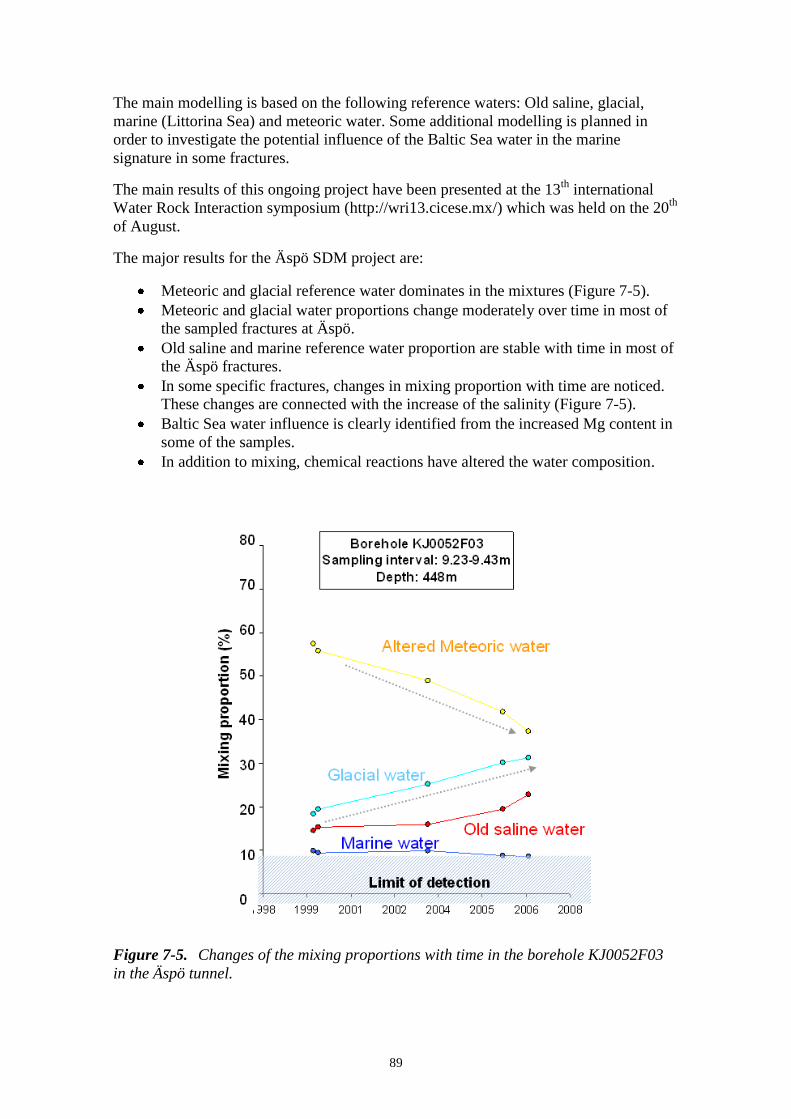
89
The main modelling is based on the following reference waters: Old saline, glacial,
marine (Littorina Sea) and meteoric water. Some additional modelling is planned in
order to investigate the potential influence of the Baltic Sea water in the marine
signature in some fractures.
The main results of this ongoing project have been presented at the 13th
international
Water Rock Interaction symposium (http://wri13.cicese.mx/) which was held on the 20th
of August.
The major results for the Äspö SDM project are:
Meteoric and glacial reference water dominates in the mixtures (Figure 7-5).
Meteoric and glacial water proportions change moderately over time in most of
the sampled fractures at Äspö.
Old saline and marine reference water proportion are stable with time in most of
the Äspö fractures.
In some specific fractures, changes in mixing proportion with time are noticed.
These changes are connected with the increase of the salinity (Figure 7-5).
Baltic Sea water influence is clearly identified from the increased Mg content in
some of the samples.
In addition to mixing, chemical reactions have altered the water composition.
Figure 7-5. Changes of the mixing proportions with time in the borehole KJ0052F03
in the Äspö tunnel.
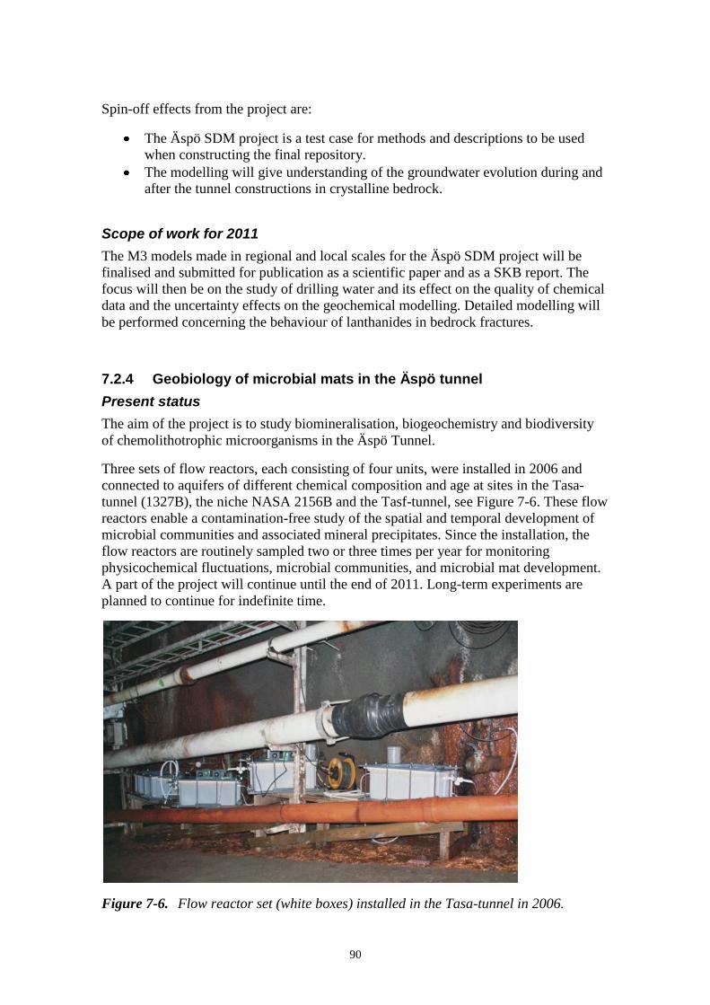
90
Spin-off effects from the project are:
The Äspö SDM project is a test case for methods and descriptions to be used
when constructing the final repository.
The modelling will give understanding of the groundwater evolution during and
after the tunnel constructions in crystalline bedrock.
Scope of work for 2011
The M3 models made in regional and local scales for the Äspö SDM project will be
finalised and submitted for publication as a scientific paper and as a SKB report. The
focus will then be on the study of drilling water and its effect on the quality of chemical
data and the uncertainty effects on the geochemical modelling. Detailed modelling will
be performed concerning the behaviour of lanthanides in bedrock fractures.
7.2.4 Geobiology of microbial mats in the Äspö tunnel
Present status
The aim of the project is to study biomineralisation, biogeochemistry and biodiversity
of chemolithotrophic microorganisms in the Äspö Tunnel.
Three sets of flow reactors, each consisting of four units, were installed in 2006 and
connected to aquifers of different chemical composition and age at sites in the Tasa-
tunnel (1327B), the niche NASA 2156B and the Tasf-tunnel, see Figure 7-6. These flow
reactors enable a contamination-free study of the spatial and temporal development of
microbial communities and associated mineral precipitates. Since the installation, the
flow reactors are routinely sampled two or three times per year for monitoring
physicochemical fluctuations, microbial communities, and microbial mat development.
A part of the project will continue until the end of 2011. Long-term experiments are
planned to continue for indefinite time.
Figure 7-6. Flow reactor set (white boxes) installed in the Tasa-tunnel in 2006.
91
In addition to high-resolution mineral, element and biomolecular studies of mineralising
microbial mats, corresponding studies are performed on SKB drill cores to elucidate
biosignatures of fossil deep biosphere communities in fracture minerals. These studies
are performed using Time-of-Flight secondary ion imaging mass spectrometry (ToF-
SIMS, in co-operation with SP, Borås) and Raman spectroscopy.
16S rDNA-DGGE analyses reveal that fluid-borne microorganisms (of aquifers down to
location 2156B) largely reproduce the pristine mat structures and compositions in the
flow reactors compared to an open pond system. Sulphate-reducing bacteria similar to
Desulfolobus propionicus, Desulfobacterium autotrophicum and Desulfotalea
psychrophila, as well as the methanotrophs Methylomonas sp. and Methylobacter sp.
have been shown to occur ubiquitously in all mat systems. Microbial mats dominated by
the iron-oxidisers Mariprofumdus sp. and Gallionella ferruginea, are generally
multilayered systems containing also bacteria similar to ammonia-oxidisers like
Nitrosomonas sp., to the sulphur-oxidising Thiocapsa sp., and the lithoheterotrophic
alpha-proteobacterium Citricella thiooxidans. The aquifer of the deepest section (TASF)
clearly differs from all other sites investigated with respect to community composition,
biofilm structure and complexity.
Analysis of Trace and Rare Earth Element (TREE) accumulations within iron oxidising
microbial mat communities in the dark and air-tight flow reactors in the Tasa-tunnel
(1327B) and the nisch (NASA 2156B) revealed a massive (up to 106 fold) accumulation
of most of the TREE within the mineralised microbial mats after two and nine months,
respectively, see Figure 7-7.
Time-of-flight secondary ion mass spectrometry (ToF-SIMS) was implemented as a
new method for identifying organic biomarkers and spatially resolves their distribution
directly on geobiological samples. ToF-SIMS imaging was successfully applied to
microscopic cryosections of mineralised microbial mats to correlate specific lipid
biomarkers (e.g. glycerophospholipids, archaeal tetraether lipids) with their
source organisms.

92
Figure 7-7. Trace and rare earth element accumulation within iron oxidising
microbial mats in dark and air-tight flow reactor at TASA 1327B after 2 and 9 months
respectively (normalised on the supplying aquifer).
An integrated geochemical approach to microbial biosignatures preserved in fracture
minerals obtained from drill core KJ 0052F01 enabled the identification of several
fracture mineral generations and a putative ancient biofilm that may have existed during
a late glacial period, when the fracture was reactivated and water conducting.
Microbial mats accumulating TREE may potentially be used for the recovery of
precious trace elements, and for water remediation purposes. These microbial
communities or synthetic systems with similar properties may serve as an organic
filter/buffer also for capturing radionuclides. Defining biosignatures of recent and
ancient deep biospheres will be helpful for palaeo-environmental reconstructions, which
may also support considerations about the long-term storage of nuclear waste.
Scope of work for 2011
The work during 2011 will include:
Two field campaigns will be conducted to continue the long-term monitoring of
in/out-flowing water and of the microbial mats in the flow reactors. An interim
evaluation of the obtained data sets will be carried out.
In situ colonisation experiments will be continued with time-serial sampling.
ToF-SIMS measurements with the resulting mat sections will be performed in
co-operation with SP (Borås). Further microorganisms from pure and batch
cultures as well as lipid standards will be used as references for the identification
of biomarker sources in environmental samples from the underground sites.

93
For the detection of palaeo-biosignatures, drill cores with fracture minerals
already sampled from the SKB core library will be subjected to petrographic,
microscopic and (bio)geochemical analysis (LA-ICP-MS, ToF-SIMS, GC/MS,
LC/MS and isotope measurements.
High-resolution studies will be continued on iron-oxidising and phototrophic
microbial mats in co-operation with the MPI (Bremen). Functional gene analysis
and tracer experiments with isotopically labelled substrates will enable the
identification and characterisation of metabolic pathways of specific organisms.
Proteomic analysis will be applied and adapted where required on matrix-
forming polysaccharides in environmental biofilms.
Sites will be selected and prepared for a drilling campaign aimed on the
geochemistry and (palaeo-) biosignatures of fracture minerals.
7.2.5 Coastal modelling
Present status
The aim of the project is to study hydrogeological pathways and coastal dynamics with
integrated transport and altering processes in water from land to the sea. A DarcyTools
flow model for Forsmark has now been completed. Compared to earlier Forsmark
models, new surface elevation data and also newly developed surface hydrology
features have been included. This enables to obtain more complete flow patterns from
soil infiltration to the Baltic Sea, including flow through the surface waters (lakes and
streams), the overburden and the bedrock in greater detail than has been done in the
past. All flow is assumed to be laminar and driven by pressure/gravity. In its current
form, the model assumes a uniform (average) aquifer depth. Additional complexity of
the spatially variable overburden/soil depth in the catchment is now added by using the
developed soil model from SKB. With this feature, the model will capture all major
structural complexity, from complicated sub-catchments and surface water areas, to
variable overburden and conducting fracture zones of the bedrock. Testing of the flow
model is currently in progress in collaboration with experienced model developers.
Once the flow testing is completed, particle tracking will be implemented for computing
the water transit times within the catchment, and evaluating the flow/transport
partitioning between different sub-domains (surface and subsurface). Identification of
the hydrological pathways and transit times will provide key quantities for
understanding the basic hydrology and for investigations of reactive transport and
geochemical analysis of the existing data, or for geochemical modelling.
Scope of work for 2011
During 2011 at least two manuscripts will be finished where transit time distributions
are coupled with transport processes for the Forsmark catchment and where general
conclusions about transport characteristics and interactions between flow systems in
similar coastal catchments will be made. The aim is to extend the modelling to
Oskarshamn catchment, even if some site-specific data is lacking there.
The continuing work is planned to follow two tracks; one where there are some ideas to
couple modelling results with available isotopic data to aim for a more complete view of
catchment flowpaths. The other track is to start the upscaling project of the flow and

94
transport partitioning results from the Forsmark/Oskarshamn modelling to larger-scale
hydrological modelling in the Baltic Sea catchment.
Some geographical data for this has been compiled and collected during the summer of
2010 but the modelling work has to be completed. The results are planned to be
presented at conferences as well as in journals, e.g. EGU in spring and AGU in the fall.
7.2.6 3D localisation system of persons, the Alfagate project
Present status
The aim is to develop and apply RFID (Radio Frequency Identification) technology in
tunnel environment. The technology is used to identify in 3D persons or objects in the
tunnel environment. The project creates an open software structure which is not
dependent of hardware and which will be integrated with other Äspö HRL systems.
The server software/driver Charon is used as the link between the hardware and the
database within the Alfagate project. AlfaGate Admin is the software which handles the
administrative parts of the system. The AlfaGate Tracker is the visualisation part of the
system which shows the locations of the persons in the tunnel (Figure 7-8) and is used
in the control room. A simpler version of the visualisation system is the AlfaGate
Viewer which is used in areas for the public. AlfaGate Pending is the gateway system
controlling persons entering and leaving the tunnel.
Figure 7-8. AlfaGate Tracker is the visualisation system which shows the locations of
the persons in the Äspö HRL.
The status of the project is that it is in the development phase towards the commercial
systems of TaggMaster, Aeroscout and Identec.
The major results are that the AlfaGate system is further developed towards the
Identec‟s RFID HW and supports TagMasters RFID HW systems.
The spin-off effect from the project is that there is a great commercial interest for the
system in Sweden and abroad. Additional local competences are needed in the company
and co-operation agreements with local companies are discussed.
95
Scope of work for 2011
Further development and integration with world leading Identic‟s products are planned.
There is a great interest from other companies to join the project.
7.2.7 Integrated fire protection, the Safesite project
Present status
SKB requires a fire security system based on the best available technology. The aim of
the Safesite project is to integrate the detection and verification of smoke or fire
together with the entrance and logistic control of people and vehicles. True integration
with the RFID system and other security systems are required.
The major results are that international companies such as Siemens and Niscaya have
shown great interest and are included in the testing and verification of the system to be
installed.
The spin-off is great interest from companies and organisations to follow the
development of the Safesite system.
Scope of work for 2011
A detailed investigation of specifications associated with SKB‟s facilities at Äspö, Clab,
SFR and for the final storage has been conducted. During year 2011 the detailed
specifications will be established for the Äspö HRL and a test facility will be
constructed. Here tests and research will be conducted to meet the SKB requirements
concerning fire protection but also to support the research conducted by the companies
Niskaya and Siemens. The aim is also to integrate RFID technology at the end of year
2011.
7.2.8 Utilisation of waste energy, the EoS project Present status
The Eden of Sweden (EoS) project focuses on utilising of waste energy from different
industrial process plants. EoS is aiming at demonstrating the latest technology for
energy efficiency e.g. within housing, water cleaning, leisure facilities, greenhouse
production and as a research facility. The project is of national and international interest
due to the huge amount of waste heat available globally and which can be utilised as a
resource. The spin-off effect of this project is that it will create local competence in a
field of potential global interest. A feasibility study is ongoing and will list about five
possible research projects within the field of utilisation of low graded heat.
Scope of work for 2011
Funding is needed for making applications to EC for different energy projects in and in
Sweden including the Swedish Energy Agency. The main project can start in 2011 or
2012 if funding is provided.

96
7.2.9 Detailed fracture mineral investigations Present status
The aim of the project is to characterise and gain information from fracture minerals in
bedrock fractures. Investigations of fracture minerals provide a useful tool to understand
palaeohydrogeological conditions. Groundwater in crystalline rocks is mainly
transported along fractures and different groundwater subsequently flowing along
fractures may precipitate a sequence of minerals on the fracture walls. Examination of
these mineral coatings ideally yields a palaeohydrogeological record of formation
temperatures, fluid compositions and potential origin. The project will lead to
publications of several scientific papers on fracture minerals and their input to the
understanding of past and present redox conditions in the bedrock, groundwater-mineral
interactions, biological activity in bedrock fractures, stability of groundwater systems in
Proterozoic rocks etc.
Scope of work for 2011
Plans for 2011 involves further investigations of fracture minerals from Äspö, Laxemar
and from the Greenland Analogue Project, regarding both palaeohydrogeological
information based on stable isotope fractionations and trace element variations, as well
as on past and present redox fluctuations revealed by a multiple-method approach.
7.2.10 Expert group for the harbour remediation project in Oskarshamn Present status
The aim of the expert group is to support and scientifically review the harbour
remediation project in Oskarshamn. An expert group under the management of Nova
FoU has been formed consisting of experts from the company Land, Water and Waste
Management Group AB (LWWMG) and from the institution of Natural science at the
Linnaeus University.
Scope of work for 2011
The review and support work for the harbour remediation project will continue during
the year 2011. Regular project meetings and workshops are planned to be performed
during the year.

97
7.2.11 Hydrochemical interaction between a tunnel and its surroundings – development of prediction models
Present status
Investigations carried out show that groundwater recharge in rock increases during the
building phase of underground constructions. The project has the following aims:
Provide a deeper insight into and quantify chemical changes in surface water and
groundwater caused by underground construction within a catchment area.
Create an understanding of how the chemical change in the groundwater caused
by underground construction can in turn affect reinforcements in the
underground constructions, grouting measures and the functioning of the
drainage system.
To further develop numerical modelling tools that are used to facilitate the use
of the data gathered before the construction phase of an underground facility.
The models are used to assess the hydrochemical conditions during the
construction, and operational phases of the facility.
Research and development initiatives will also provide a basis for improving the content
of environmental impact assessments in conjunction with underground projects.
Furthermore the project aims to provide a basis for constructing safer tunnels with cost-
effective maintenance.
Scope of work for 2011
The primary focus of the proposed project is to use acquired knowledge to create
prediction models with the aim to predict hydrochemical changes in conjunction with
underground construction, based on information gathered prior to the construction
phase.
During 2011, the collection of hydrological and hydrochemical data from primarily two
different underground construction projects will be carried out. Furthermore,
hydrochemical modelling is planned to be initiated during the autumn of 2011.

98

99
8 International co-operation
8.1 General
Eight organisations from seven countries will in addition to SKB participate in the co-
operation at Äspö HRL during 2011. Six of them; Andra, BMWi, CRIEPI , JAEA,
NWMO and Posiva together with SKB form the Äspö International Joint Committee
(IJC), which is responsible for the coordination of the experimental work arising from
the international participation. Nagra left the central and active core of participants 2003
but are nevertheless supporting the Äspö activities and participates in specific projects.
NUMO (Nuclear Waste Management Organisation of Japan) has currently an observer
role at the IJC-meetings and is foreseen to be the Japanese representative in the IJC in
the near future. However CRIEPI and JAEA will still be performing the actual technical
work in the co-operation.
Several of the participating organisations take part in the two Äspö Task Forces on: a)
Modelling of Groundwater Flow and Transport of Solutes, which is a forum for co-
operation in the area of conceptual and numerical modelling of groundwater flow and
solute transport in fractured rock and b) THMC modelling of Engineered Barrier
Systems, which is a forum for code development on THMC processes taking place in a
bentonite buffer and gas migration through a buffer.
SKB also takes part in work within the IAEA framework. Äspö HRL is part of the
IAEA Network of Centres of Excellence for training in and demonstration of waste
disposal technologies in underground research facilities.
SKB is actively involved in the European technology platform IGD-TP (“Implementing
Geological Disposal of Radioactive Waste Technology Platform) which was launched
in November 2009. The platform´s vision is that by 2025 the first geological disposal
facilities for spent fuel, high-level waste, and other long-lived radioactive waste will be
operating safely in Europe. The platform currently involves eleven waste management
organisations and in addition 58 participants from industry, research organisations,
research centres, academia, technical safety organisations and
non-governmental organisations in Europe. Research in the Äspö HRL is foreseen to be
an important part of the joint work in the platform during coming years.
8.2 Andra
Andra, the French radioactive waste management agency, operates an Underground
Rock Laboratory (URL) in a clay-rich rock formation located in the Meuse/Haute-
Marne District. In 2010, Andra proposed a site for the deep geological disposal of high
and intermediate level long-lived radioactive waste to the French government. If the
licence is granted in 2016, the geological disposal facility, called CIGEO, will be
operational in 2025.
In late 2010, Andra launched an administrative process to obtain a licence for the
management of the URL until 2030. The aim of this process is to develop an extensive
research and development programme concurrently with the construction of the disposal
facility.

100
The main scientific issues are as follows:
Interaction between the materials involved (iron, glass, clay, cement) and the
rock in natural conditions.
Construction and management of the disposal cells.
Sealing of the shafts and drifts.
In this context, although Andra has given up its research in a crystalline host rock, it has
been decided to carry on the co-operation with Äspö HRL. A renewed four year co-
operation agreement with SKB was signed in 2008.
Prioritised activities during 2011
Temperature Buffer Test and Task Force on Engineered Barrier Systems.
After the dismantling of the Temperature Buffer Test (TBT) and the retrieval of the
canister, year 2011 will be devoted to sample analyses and data interpretation. The
French support to the Task Force on Engineered Barrier Systems (Task Force EBS) will
be provided by the Spanish UPC-CIMNE modelling team using the Code_Bright.
A sample analysis report will be issued in 2011. A first modelling report taking into
account the thermo-hydro-mechanical coupling will assess the knowledge on the
behaviour of the buffer and the ability to analyse it. A technical meeting between the
UPC modelling team and the Clay Technology modelling team will be held in Paris in
June 2011. The final report on this experiment will be released in 2012.
Large Scale Gas Injection Test (Lasgit)
In the framework of the European Project Forge, Andra will carry on its participation in
the follow up of the Lasgit experiment, but it‟s on-site activities will focus on the Bure
experiment of the Forge project.
Alternative Buffer Materials (ABM)
Two technical reports were issued in 2010: i) "Investigation of the iron-clay corrosion
interface from the ABM Experiment (Aspö, Sweden)” M. Schlegel (CEA Saclay) and
ii) "Projet ABM (Alternative Buffer Materials) Caractérisation par microscopies
électroniques des transformations minéralogiques de différents matériaux argileux
placés au contact d‟un corps en acier chauffant ou non" de R. Mosser-Ruck (G2R in
french).
Andra will carry on its participation in the ABM project. At the last technical meeting
held in April 2010, Andra presented the areas they will contribute in during 2011:
Characterisation of initial samples for in-depth understanding of the evolution of
CEC and minor elements
Nitrogen adsorption experiments for MX80, Deponit and FEBEX samples.
New projects
Andra intends to participate in the dismantling of the Prototype. Its contribution will be
defined at a later stage.

101
8.3 BMWi
In 1995, SKB and the Bundesministerium für Forschung und Technologie (BMFT)
signed the first project agreement being the basis for co-operation in specific projects
performed in the Äspö HRL. After a first extension in 2003, the agreement was once
again extended in 2008 for a period of another five years. Several research institutes are
performing the work on behalf of and funded by the Bundesministerium für Wirtschaft
und Technologie (BMWi) which is responsible for site-independent R&D: the Federal
Institute for Geosciences and Natural Resources (BGR), DBE Technology GmbH,
Forschungszentrum Dresden-Rossendorf, Institute of Radiochemistry (FZD/IRC), and
Gesellschaft für Anlagen- und Reaktorsicherheit mbH (GRS). The main objectives of
the co-operation within the Äspö HRL programme are to improve the knowledge on the
engineered barrier system and - on a minor scale – to keep the information up-to-date on
alternative host rocks for radioactive waste repositories. Topics of special interest are:
The behaviour of engineered barrier system and the interaction with the
surrounding rock.
The behaviour of the buffer material.
The behaviour of microbes and colloids and their interaction with radionuclides.
Geochemical investigations of the migration behaviour especially of actinides
under near-field and far-field conditions.
Characterisation of fracture zones in the rock mass and disturbed zones
surrounding underground openings, and flow and transport of solutes.
Prioritised activities during 2011
Microbe Project
The contribution of the FZD is focused on the characterisation of interaction processes
of selected actinides (U, Pu, and Cm) with biofilms generated by Äspö relevant bacteria.
The issues addressed in the ongoing study are: (i) generation and characterisation of
biofilms produced by Äspö bacteria under aerobic conditions, (ii) studying the
interaction of U, Pu, and Cm with these biofilms, and (iii) spectroscopic characterisation
of the formed actinide species. The project explores interaction processes of the Äspö
bacterium Pseudomonas fluorescens in form of both planktonic cells and fixed in a
biofilm with selected actinides. First cultivation experiments under sterile and aerobic
conditions in a previously tested biofilm reactor with a succinate medium did not
succeed in the formation of a P. fluorescens biofilm. A new experiment was started
using a synthetic nutrient medium. Therefore, the former proposed activities had to be
modified in introducing studies exploring the uranium interactions of planktonic cells of
P. fluorescens. This includes growing tests in different media to be selected for the
biofilm experiments.
102
The activities planned in 2011 will comprise:
Continuation of cultivation tests to grow biofilms of the Äspö bacterium
Pseudomonas fluorescens in biofilm-reactors under sterile and aerobic
conditions.
Characterisation and quality control of the formed P. fluorescens biofilms.
Starting up of interaction experiments of U(VI) with these biofilm.
Continuation of characterising U(VI) interaction processes with metabolically
active planktonic cells of P. fluorescens, comparison with metabolically almost
inactive planktonic cells;
Characterisation of Cm(III) interaction processes with metabolically almost
inactive planktonic cells of P. fluorescens.
Prototype Repository
GRS will continue the measurements of the electric resistivity distribution in the
backfill, the buffer and the rock between two of the deposition boreholes until the
excavation of the outer section of the Prototype Repository, which is planned for 2011.
The tomographic dipole-dipole measurements are performed automatically. By inverse
modelling the resistivity distribution is derived in the cross section of the electrode
arrays. It can be related to water content of the rock or the backfill using laboratory
calibration results. Because of the failure of a number of buffer electrodes the buffer
measurements can no longer be evaluated by inversion. The measurements indicate that
the backfill is water saturated. The rock near deposition hole #5 shows slight
fluctuations in resistivity, but on the whole it shows resistivity values expected for
saturated rock.
After shutdown and dismantling of the outer section of the Prototype repository,
samples will be taken from the buffer and the backfill and analysed in the GRS
laboratory at Braunschweig considering water content and resistivity in order to
confirm the in situ measurement results. A number of electrodes from the buffer and
from the backfill will be retrieved and inspected in order to determine the reason for
electrode failures.
Alternative Buffer Materials
All results obtained on the 10 different bentonite blocks were summarised in the frame
of the BGR progress report. Based on this internal report “Ideal bentonite” and the
project meeting in April 2010 in Lund the most interesting result is the obvious
redistribution of the exchangeable cations. According to the experimental setup blocks
produced from rather different bentonite materials were in contact throughout the
heating period. Apart from chemical and mineralogical differences, the bentonites had a
completely different exchangeable cation population. BGR results proved that this
exchangeable cation population changed significantly. Obviously a rather complete
cation exchange process occurred in the vertical direction, e.g. from one bentonite block
to the other. Such an observation was never made before. Therefore, the 2010 research
concentrated on the characterisation of this phenomenon.
The interface between different bentonite blocks which stuck together after the
experiment was investigated. BGR initiated a project (internal round robin-like test)
called „laboratory exchange of cation exchange capacity and exchangeable cation
measurements using the “Cu (II)-triethylentetramine” method which is based on

103
„Alternative buffer material test‟ reference materials. This test is conducted in order to
prove the comparability of the results of exchangeable cation population from different
laboratories.
In 2011 the results of the cation exchange round robin-like test will be assessed,
discussed on the project meeting, and published either as report or peer reviewed article.
Temperature Buffer Test DBE TECHNOLOGY has recently developed a methodology for simulating the
thermo-mechanical behaviour of claystone by applying a discontinuous numerical code
(PFC). A calibrated model for the Opalinusclay as a host rock is already available. A
corresponding model for the compacted buffer clay “bentonite” is still pending.
Up to now, a simulation of a borehole disposal system consisting of canister, heat
spreader (sand), bentonite buffer, excavation damaged zone (EDZ) and intact host rock
is done using a combination of continuous (FLAC3D) and discontinuous numerical
simulations with different computer codes (PFC, UDEC, 3DEC), which, however, still
is an insufficient and ineffective method. Especially the simulation of the long-term
behaviour of the system with focus put on long-term void space reduction within the
EDZ and the geotechnical barrier material needs a consistent and improved model.
Therefore, in 2011 it is intended to develop a calibrated discontinuous model for the
geotechnical barrier material bentonite (and sand). The huge amount of monitoring data
obtained during the Temperature Buffer Test regarding temperature and pressure
evolution within the bentonite buffer offers an excellent possibility for developing a
well calibrated model.
Large Scale Gas Injection Test
BGR‟s activities within the Large Scale Gas Injection Test (Lasgit) project focus on the
investigation of processes and interactions that occur in the experiment, particularly
with regard to the behaviour of the engineered barrier system and the influence of the
excavation damaged zone (EDZ). Test evaluation and modelling exercises are executed
using the finite-element code OpenGeoSys (THMC-code).
The work in 2011 will concentrate on the modelling of gas transport processes in the
engineered barrier system. The measured data from Lasgit will be used to validate
different approaches for the simulation of gas migration.
Task Force on Engineered Barriers
In 2010, the Task Force on Engineered Barrier Systems has started into a new phase.
The issues C and THM will be treated separately at first. Main activity of the C- issue is
focused on microstructural aspects and their influence on modelling of diffusion and
swelling, and, moreover, on coupling aspects of HM-and C-models.
The THM-issue concerns the buffer-rock interaction and the processes involved. In
2011, both GRS and BGR plan to work on this topic. Main activities comprise studying
the effects of parameter uncertainties on the results of THM-coupled calculations of
engineered barrier systems and sensitivity analysis. The codes used are
GeoSys/Rockflow (BGR) and VIPER (GRS).
104
Moreover, GRS intends to continue simulating the re-saturation process by using the
code VIPER. Additionally it is intended to study the possibility of coupling VIPER with
GRS´s single-phase groundwater code d3f and study the possible application in
Benchmark Task 8.
8.4 CRIEPI
Central Research Institute of Electric Power Industry (CRIEPI) signed a contract with
SKB for the Äspö HRL Project in 1991 and renewed it in 1995, 1999, 2003 and 2007.
The main objectives of CRIEPI‟s participation have been to demonstrate the usefulness
of its numerical codes, develop its site investigation methods and improve the
understanding of the mechanisms of radionuclide retention in fractured rock and the
interaction between engineered barriers and surrounding rock. Since 1991, CRIEPI has
participated in the exchange of information concerning research and technology for
geological disposal of high-level radioactive wastes with other organisations within the
Äspö HRL co-operation. In addition, CRIEPI has performed several voluntary tasks e.g.
groundwater dating, fault dating, measurement of velocity and direction of groundwater
flow and a study on impact of microbes on radionuclide retention. CRIEPI has
participated in the Task Force on Modelling of Groundwater Flow and Transport of
Solutes since 1992 and also in the Task Force on Engineered Barrier Systems since
2004.
Prioritised activities during 2011
During 2011, CRIEPI will participate in the two Task Forces as well as exchange
information about research, technologies and methodologies for geological disposal of
high-level radioactive wastes with SKB and the other participating organisations.
As to the Task Force on Modelling of Groundwater Flow and Transport of Solutes,
CRIEPI will compile a report on modelling results for Task 7, Reduction of
performance assessment uncertainty through modelling of hydraulic tests at Olkiluoto,
Finland. CRIEPI will also conduct modelling work for Task 8, Interface engineered and
natural barriers.
For the Task Force on Engineered Barrier Systems, CRIEPI has applied its own
numerical code for the thermo-hydro-mechanical coupled behaviour, LOSTUF, to
several benchmark issues. In 2011, it is planned to apply LOSTUF to simulations for of
the Prototype repository. A series of sensitivity analyses will also be conducted by
LOSTUF in order to understand which material parameters and boundary conditions
have great effects on numerical results.
8.5 JAEA
The JAEA participation in the Äspö HRL through 2010 has been carried out according
to the trilateral project agreement between JAEA, CRIEPI and SKB signed in 2006.
Starting in 2011, JAEA‟s participation at Äspö will be carried out under a new project
agreement between NUMO and SKB.
JAEA is continuing to construct complementary underground research laboratories in
fractured granite at Mizunami and in a sedimentary formation at Horonobe. These
105
laboratories, and JAEA‟s participation at Äspö, aim to establish comprehensive
techniques for investigating the geological environment and to develop a range of
engineering techniques for deep underground applications. The results obtained from
these laboratories will contribute to ensure the reliability of repository technology and to
establish a safety assessment methodology.
JAEA‟s active participation at Äspö supports the goals of the Japanese Radioactive
Waste Management programme to improve site characterisation and repository
development technologies. The objectives of JAEA‟s participation in Äspö HRL during
2011 will be to:
Develop technologies applicable for site characterisation.
Improve understanding of flow and transport in a fractured rock.
Improve understanding of behaviour of engineered barriers and surrounding host
rock.
Improve techniques for safety assessment by integration of site characterisation
information.
Improve understanding of underground research laboratory experiments and
priorities.
These objectives are designed to support high level waste repository siting, regulations
and safety assessments in Japan.
Prioritised activities during 2011
JAEA plans to actively participate in Tasks 7 and 8 of the Task Force on Modelling of
Groundwater Flow and Transport of Solutes, especially to improve the characterisation
of flow and transport properties of rock fractures in the geosphere, and their interaction
with engineered barriers.
JAEA‟s participating in Task 8 will also support the evaluation of heterogeneous flow
paths in fracture networks, including local in-plane heterogeneity and microstructural
conditions. This will assist in the evaluation of canister near-field conditions. In
addition, for the Alternative Buffer Materials (ABM) project, several analyses such as
X-ray diffraction for the parcel 1 (one year test) will be advanced, with the aim to
identify mineralogical changes in the Japanese bentonite (one of eleven clay materials
used in the ABM-test parcels).
8.6 NWMO
The prime objective of Nuclear Waste Management Organization‟s (NWMO‟s)
participation at Äspö HRL is to enhance the scientific understanding and technology
base for a deep geological repository through international co-operation research and
development projects and demonstrations. The planned work on Äspö HRL projects to
be carried out in 2011 is described below.
Prioritised activities during 2011
NWMO is participating in the Task Force on Modelling Groundwater Flow and
Transport of Solutes, with respect to Task 7. The Canadian modelling team is from the
Université Laval and the reference code is FRAC3DVS. In 2011, project activities will
106
include completion of the final Task 7 report summarising modelling methodologies
and findings for sub-tasks 7A, 7B and 7C.
NWMO is providing modelling support for the Large Scale Gas Injection Test (Lasgit)
using the Tough2 code modified with pressure-dependent permeability and capillary
pressure to simulate microfracturing. In 2011, the modelling work will continue with
efforts to simulate the gas injection tests conducted in 2009. The goal of this simulation
work is to better understand the processes taking place during the gas injection portion
of the Lasgit experiment and to identify areas where the current modelling approach is
not performing as desired. Research into alternative numerical modelling systems is
underway. This work will continue in 2011, exploring alternative modelling platforms
that include geomechanical processes, in addition to the two-phase flow considered in
earlier work. NWMO will continue this broad-ranging assessment of possible solutions
to this difficult modelling problem. It is hoped that a successful modelling effort will
allow us to analyse gas injection scenarios related to the Lasgit experiment.
NWMO is participating in the Task Force on Engineered Barrier Systems, with respect
to the THM modelling task. In 2011, the planned modelling work will focus on
completion of the numerical simulation of in-situ repository technology.
The NWMO will also be participating in the dismantling of the outer section of the
Prototype repository.
8.7 Posiva
Posiva‟s co-operation with SKB continues with the co-operation agreement signed in
the autumn of 2006. The focus of the co-work has been organised in areas related to
how a final repository for spent nuclear fuel is designed and produced and safety related
research.
Posiva also contributes to several of the research projects within Natural barriers. The
implementation and construction of the underground rock characterisation facility
Onkalo at Olkiluoto in Finland give possibilities to co-operate within the research and
development of underground construction technology. Posiva‟s co-operation is divided
between Äspö HRL activities and more generic work that can lead to demonstrations in
Äspö HRL.
Prioritised activities during 2011
KBS-3 Method with Horizontal Emplacement
SKB and Posiva are engaged in an R&D with the overall aim to investigate whether the
KBS-3H concept can be regarded as a viable alternative to the KBS-3V concept. The
project is jointly executed by SKB and Posiva and has a common steering group.
During 2008-2010 complementary studies of horizontal emplacement was executed.
The target was to solve a number of pre-designed issues and conduct component tests in
the field and select the most appropriate design. Also full-scale system tests in a
representative environment were planned. At the moment, the next project phase
"KBS-3H Description update and performance of full scale tests, 2011-2014" is under
planning.

107
Large Scale Gas Injection Test
SKB and Posiva have conducted a joint Lasgit-project since 2003. Co-operation in
conducting the experimental programme will continue during the year 2011. The results
will also be used in the EC project FORGE.
Long Term Test of Buffer Materials
Posiva‟s task in this project is to study the porewater chemistry in the bentonite. The
task is carried out at VTT. The aim of the work is to obtain data about the chemical
conditions, which develop in the bentonite. The study gives information about the
chemical processes occurring in the bentonite, but also supports the other planned
studies of the chemical conditions.
Alternative Buffer Materials Posiva will contribute to the project with similar types of experimental studies as
already done in the project Long Term Test of Buffer Material. The clay materials of
interest in the Posiva‟s studies are MX-80, Deponit, Asha and Friedland Clay. The
topics of interest are: chemical processes in the porewater, mineralogical changes of
buffer materials and changes in physical properties of buffer materials (swelling
pressure, hydraulic conductivity). The results of the analyses will be reported 2011.
Task Force on Modelling of Groundwater Flow and Transport of Solutes
Äspö Task Force Task 7 - “Reduction of Performance Assessment uncertainty through
block scale modelling of interference tests in KR14-18 at Olkiluoto” - will be completed
in 2011. A journal article or articles describing the achievements will be prepared.
Äspö Task Force Task 8 - "Modelling the interaction between engineered and natural
barriers – An assessment of a fractured bedrock description in the wetting process of
bentonite at deposition tunnel scale" - is intended to be a joint effort of the Task Force
on Groundwater Flow and Transport of Solutes and The Task Force on Engineered
Barrier Systems. The focus is on the hydraulic interaction between the bentonite clay
and near-field host rock.
In 2011 Task 8, that involves numerical modelling of the so called BRIE experiment,
will, as its sub-task 8b, carry out scoping calculations. The objective is to shed light on
the means of incorporating unsaturated rock in the models for bentonite saturation at
repository conditions, and appropriate form of boundary conditions for the deposition
tunnel (fixed pressure or flux). These scoping estimations will treat the surrounding
bedrock both as porous medium and fracture network embedded in diffusive rock
matrix skeleton. Sub-task 8e will then move on evaluating the effects of the location of
a bedrock fracture along the deposition hole on the wetting of the bentonite buffer. In
addition to these scoping calculations, the subsequent sub-task 8c will produce
hydrogeological model prediction of the central borehole of the planned experiment site.
Moreover, year 2011 objectives will include preliminary predictions for the bentonite
wetting (sub-task 8d).

108
Task Force on Engineered Barrier Systems
During the year 2011 Posiva will participate in the following tasks:
dismantling of the Prototype Repository.
modelling of Task 8 (BRIE).
investigation of bentonite homogenisation.
sensitivity analyses for rock-buffer-canister-system.
Posiva is also participating in the work of Chemistry Group.
Retrieval of Prototype Repository
Posiva participates in the project on the dismantling of the outer section of the Prototype
repository during 2011. Posivas main activities are to contribute to the modelling work
and laboratory analyses related to behaviour of buffer and backfill.
Bentonite Laboratory
SKB and Posiva are jointly developing the deposition tunnel backfill concept and part
of the work will be done in Finland and part in Sweden. Projects like pellet optimisation
and handling of inflows during backfilling (technical methods) requires large scale
testing and the Bentonite Laboratory at Äspö HRL is mainly the place for the tests.
Deposition tunnel plug
SKB has a detailed design for deposition tunnel plug and it will be demonstrated by
constructing a full scale plug in 2011/2012. Information on performance of the plug and
its requirements, excavation methods, concrete recipe is needed before plug
construction. Posiva is developing an own plug design and part of the work will be done
jointly. The decision on Posiva‟s role in plug demonstration will be done in 2011.
8.8 KAERI
Korea Atomic Energy Research Institute (KAERI) signed an agreement with SKB for
collaboration on research for groundwater flow and solute transport modelling at a
radioactive waste disposal site at 2007. KAERI has therefore joined the Äspö Task
Force on Modelling of Groundwater Flow and Transport of Solutes which is a forum of
international organisations for modelling of groundwater flow and solute transport in
fractured rocks.
Prioritised activities during 2011
KAERI will perform the task as a member of the Äspö Task Force on Modelling of
Groundwater Flow and Transport of Solutes, and exchange the knowledge with SKB
and other participating members. The sub-task 7C, which is related to simulation of
groundwater flow in a single fracture using borehole logging data, hydraulic test results
and Posiva Flow logging (PFL) data, will be completed, and a progress report on the
results of the Task 7 will be submitted to the Task Force. KAERI will also conduct the
Task 8 on modelling the interaction between engineered and natural barriers following
the schedule of the Task Force.
109
8.9 Nagra
The Nationale Genossenschaft für die Lagerung Radioaktiver Abfälle, Nagra, has the
task to provide scientific and technical basis for the safe disposal of radioactive waste in
Switzerland. Nagra has had agreements with SKB for participation in Äspö HRL since
1994 to include mutual co-operation and participation in Äspö HRL and Grimsel Test
Site projects. The last agreement expired 2003 and Nagra left the central and active core
of participants. Nevertheless, Nagra supports the Äspö activities and participates in
specific projects.
Prioritised activities during 2011
Nagra will continue to take part in the Task Force on Engineered Barriers Systems.
During 2011 one modelling group will perform THM sensitivity analysis. Nagra will
also continue to participate in the parallel task force that deals with geochemical
processes in engineered barriers and chemical modelling of bentonite. Nagra will also
continue to participate in the Alternative Buffer Materials project and the Long Term
Test of Buffer Material experiment. For these projects, Nagra‟s activities focus on
analysis of samples and performance of laboratory tests in Switzerland.
Co-operation activities will also intensify in the EC co-funded project LUCOEX on the
test and demonstration of emplacement tests, which was formally initiated at the end of
2010.
8.10 RAWRA
RAWRA covers the activities via two subcontractors, Nuclear Research Institute, plc.
and Technical University Liberec. The work within the Task Force on Engineered
Barriers Systems is focused on the chemistry of the bentonite Rokle and/or model
development and modelling performance of engineered barriers system in geological
repository.
Prioritised activities during 2011
Porewater chemistry of Rokle bentonite
The knowledge of porewater composition is one of the key parameters for
understanding and prediction of the processes that will take place in the Deep
Geological Repository (DGR). The bentonite porewater will affect a number of
important processes, e.g. corrosion of waste package materials, solubility of
radionuclides and diffusion and sorption of radionuclides.
The Rokle bentonite differs in composition and properties from worldwide studied
MX-80, Volclay or Febex, being a mixture of (Ca, Mg)-Fe-rich montmorillonite, micas,
kaolinite with other mineral admixtures (mainly Ca, Mg, Fe carbonates, feldspars and
iron oxides). This fact leads to the need for more detailed investigation of Rokle
bentonite in order to verify its suitability as a buffer and backfill in DGR.
Generally accepted approach for studying porewater evolution is a combination of
experiments, followed by the geochemical modelling and its comparison to

110
experimental results. A similar approach was used in our study, where modelling of the
Rokle bentonite porewater using a geochemical code PHREEQC2 /Parkhurst and
Appelo 1999/ was compared with supporting experimental data, obtained by both
aqueous extraction (in deionised water under different V/m ratios) and high-pressure
squeezing.
At first, the geochemical model was successfully verified against published data for
MX-80 (for more details see /Červinka and Vejsada 2010/. Then the preliminary results
including porewater composition for non-compacted and compacted Rokle bentonite
were obtained. A comparison of experimental and calculated results is shown in
Figure 8-1. The calculated porewater of compacted Rokle bentonite (dry density 1200 –
1600 kg/m3) is of Ca-Mg-Cl-SO4-type with ionic strength between 0.06 – 0.08 mol/L
and pH 7.9. The low ionic strength in comparison to MX-80 is mainly influenced by the
concentration of Ca2+
, which is governed by calcite and gypsum equilibrium.
Further work will focus on characterisation of new Rokle bentonite to obtain input
parameters for the geochemical model and also the model itself will be improved.
Figure 8-1. Cation and anion concentrations for various solid-to-liquid ratios
(leaching and squeezing experiments), Rokle bentonite, log-log scale. Dots represent
measured concentrations of ions and lines represent calculated concentrations of ions.
Bentonite erosion in granite fracture: Ca-bentonites and their behaviour
Besides worldwide used bentonites (MX-80, Volclay or Febex) with well known
chemistry and behaviour, local Ca-bentonites with more complex mineralogy and
chemistry can also be considered as materials for both DGR buffer and backfill.
Therefore, it is necessary to know, if the bentonite may be threatened by the effect of
erosion in existing fractures in surrounding granite.
1,0E-06
1,0E-05
1,0E-04
1,0E-03
1,0E-02
10 100 1000 10000
solid-to-liquid ratio (g/l)
ion
t co
ncen
trati
on
(m
ol/l)
Na
Ca
Mg
K
Cl
SO4
Na (model)
Ca (model)
Mg (model)
K (model)
Cl (model)
SO4 (model)

111
The aim of our study is to size up the amount of bentonite particles eroded from the
swelling bentonite by the flowing water in the fracture and verify that erosion poses a
significant risk to use the Ca-bentonite as buffer material.
For this purpose, an experimental device was developed (Figure 8-2). The granite
cylinder with longitudinal artificial fracture (orange) is surrounded by compacted
bentonite (yellow). Complete sample is tightly pressed in the polycarbonate ring with
the pistons (grey), serving for the inlet and outlet of water (blue arrows). The water
flows directly to the fracture plane and the bentonite is in contact with water only at
open edges of fracture. The flow rate is maintained by peristaltic pump and outlet water
is collected in reservoir with periodical sampling.
The first set of experiments in terms of testing of experimental device has been
performed. Because of a low colloid concentration its quantification will be performed
indirectly, using aluminium concentration measurement by ICP-MS in the first step.
The measurement of particle size and particle size distribution will be tested on
Zetasizer Nano S using light scattering.
Further work will focus on testing of experimental device and possibilities of analytical
measurement of colloids (concentration and size distribution).
Figure 8-2. Cross section of experimental set up (cut in the fracture plane).

112
Task Force on Engineered Barrier Systems
Using the definition and principal characteristics of tests included in the project, tasks
will be set for model solutions, especially for the Bentonite rock interaction experiment
and the Prototype Repository. The theory describing related physical features will be
implemented. Simulation software will be developed and implemented. Respective
modules will be developed in commercial software ANSYS and COMSOL, and in
specially developed software - FLOW123D and ISERIT.
The ISERIT software needs to be extended and evaluation of the liquid phase will be
added. In ANSYS, the definition of unsaturated bentonite will be generalised, it will be
made possible to use plasticity as an input. Also, a simple variant of homogeneity
evaluation models which generalises the standard equation describing the transport of
material will be implemented. A pilot calculation of bentonite saturation from point
and/or line sources will be carried out.

113
9 References
Autio, J, 1997. Characterization of the excavation disturbance caused by boring of the
experimental full scale deposition holes in the Research Tunnel at Olkiluoto.
SKB TR-97-24, Svensk Kärnbränslehantering AB.
Andersson C, Johansson Å, 2002. Boring of full scale deposition holes at the Äspö
Hard Rock Laboratory. Operational experiences including boring performance and a
work time analysis. SKB TR-02-26, Svensk Kärnbränslehantering AB.
Andersson P, Byegård J, Billaux D, Cvetkovic V, Dershowitz W, Doe T,
Hermanson J, Poteri A, Tullborg E-L, Winberg A, 2007. TRUE Block Scale
Continuation Project. Final Report. SKB TR-06-42, Svensk Kärnbränslehantering AB.
Berglund J, Curtis P, Eliasson T, Olsson T, Starzec P, Tullborg E-L, 2003. Update
of the geological model 2002. SKB IPR-03-34, Svensk Kärnbränslehantering AB.
Červinka R, Vejsada J, 2010. Pore water chemistry of Rokle bentonite. Clays in
natural and engineered barriers for radioactive waste confinement, 4th International
Meeting, Nantes, France, March 29 – April 1, 2010, Poster, P/GC/PW/02, p. 363.
Dubois I E, Holgersson S, Allard S, Malmström M E, 2010a. Correlation between
particle size and surface area for two aluminosilicates. In P. Birkle & I.S. Torres-
Alvarado (eds) Water Rock Interaction, Taylor & Francis Group, London. p. 717-720.
Dubois I E, Holgersson S, Allard S, Malmström M E, 2010b. Dependency of BET
surface area on particle size for some granitic minerals. Accepted for publication in
Radiochimica Acta.
Garcia-Garcia S, 2009. Effect of pH and temperature on the stability of bentonite
colloid. Applied Clay Science 43, 21-26.
Garcia-Garcia S, Jonsson M, and Wold S, 2006. Temperature effect on the stability
of bentonite colloids in water. Journal of Colloid and Interface Science 298, 694-705.
Garcia-Garcia S, Wold S, and Jonsson M, 2007. Kinetic determination of Critical
Coagulation Concentrations for Sodium- and Calcium-Montmorillonite colloids in NaCl
and CaCl2 aqueous solutions. Journal of Colloid and Interface Science 315, 512-519.
Garcia-Garcia S, Degueldre C, Wold S, and Frick S, 2009. Determining
pseudoequilibrium of montmorillonite colloids in generation and sedimentation
experiments as a function of ionic strength, cationic form and elevation. Journal of
Colloid and Interface Science 315, 512-519.
Garcia-Garcia S, Wold S, and Jonsson M, 2010. Colloid transport in fracture filling
materials. Submitted to Journal of Contaminant Hydrology.
Goudarzi R, Åkesson M, Hökmark H, 2009. Äspö Hard Rock Laboratory.
Temperature Buffer Test. Sensors data report (period 030326-080701) Report No:12,
SKB IPR-09-04, Svensk Kärnbränslehantering AB.

114
Hakami H, 2003. Update of the rock mechanical model 2002. SKB IPR-03-37, Svensk
Kärnbränslehantering AB.
Holmboe M, Wold S, Jonsson M, and Garcia-Garcia S, 2009. Effects of γ-irradiation
on the stability of colloid Na+-Montmorillonite dispersion. Applied Clay Science 43.
Hökmark H, Ledesma A, Lassabatere T, Fälth B, Börgesson L, Robinet J C, Sellali
N, Séméte P, 2007. Modelling heat and moisture transport in the ANDRA/SKB
temperature buffer test. Physics and Chemistry of the Earth, 32, p753-766.
Karnland O and Birgersson M, 2006. Montmorillonite stability with special respect to
KBS-3 conditions. SKB TR-06-11.
Karnland O, Olsson S, Dueck A, Birgersson M, Nilsson U, Hernan-Håkansson T,
Pedersen K, Nilsson S, Eriksen T, Rosborg B, 2009. Long term test of buffer material
at the Äspö Hard Rock Laboratory, LOT project. Final report on the A2 test parcel.
SKB TR-09-29, Svensk Kärnbränslehantering AB.
Laaksoharju M, Gurban I, 2003. Update of the hydrogeochemical model 2002. SKB
IPR-03-36, Svensk Kärnbränslehantering AB.
Magnor B, Hardenby C, Kemppainen K, Eng A, 2007. Rock Characterisation
System - Rocs. Final report - feasibility study, phase l. State-of-the-art in 3D surveying
technology. SKB IPR-06-07, Svensk Kärnbränslehantering AB.
Parkhurst D L, Appelo C A J, 1999. User‟s guide to PHREEQC (version 2). A
computer program for speciation, batch-reaction, one-dimensional transport and inverse
geochemical calculations. USGS, Water resources investigations report, 99-4259.
SKB, 2007. Fud-programme 2010. Program för forskning, utveckling och
demonstration av metoder för hantering och slutförvaring av kärnavfall.
Svensk Kärnbränslehantering AB (In Swedish).
Smellie J A T, Waberg H N, Frape S K, 2003. Matrix fluid chemistry experiment.
Final report. June 1998-March 2003. SKB R-03-18, Svensk Kärnbränslehantering AB.
Vidstrand P, 2003. Update of the hydrogeological model 2002. SKB IPR-03-35,
Svensk Kärnbränslehantering AB.
Vilks P, 2009. Laboratory bentonite erosion experiments in a synthetic and a natural
fracture. NWMO TR-09-36, Nuclear Waste Management Organisation, Canada.
Winberg A, Andersson P, Hermanson J, Byegård J, Cvetkovic V, Birgersson L,
2000. Äspö Hard Rock Laboratory. Final report of the first stage of the tracer retention
understanding experiments. SKB TR-00-07, Svensk Kärnbränslehantering AB.
Winberg A, Andersson P, Byegård J, Poteri A, Cvetkovic V, Dershowitz W, Doe T,
Hermanson J, Gómez-Hernández J, Hautojärvi A, Billaux D, Tullborg E-L,
Holton D, Meier P, Medina A, 2003. Final report of the TRUE Block Scale project. 4.
Synthesis of flow, transport and retention in the block scale.
SKB TR-02-16, Svensk Kärnbränslehantering AB.
Åkesson M, 2006a. Temperature Buffer Test. Evaluation modelling – Field Test. SKB-
IPR 06-10, Svensk Kärnbränslehantering AB.
115
Åkesson M, 2006b. Temperature Buffer Test. Evaluation modelling – Mock-up test.
SKB IPR-06-11, Svensk Kärnbränslehantering AB.
Åkesson M, 2008. Temperature Buffer Test. Evaluation modelling – TBT_3 Mock-up
test. SKB IPR-08-09, Svensk Kärnbränslehantering AB.
Åkesson M, Jacinto A C, Gatabin C, Sanchez M, Ledesma A, 2009. Bentonite THM
behaviour at high temperatures: experimental and numerical analysis. Géotechnique 59,
No. 4, 307-318.