sourcebook • version 14 - pulselarsenantennas.com · (cst, optenni, ibwave, awr) • wifi...
TRANSCRIPT

SourceBook • Version 14

2 | [email protected] • [email protected] • [email protected]
www.pulselarsenantennas.com • 1 800 ANTENNA (268-3662) | 3
How To Work With Us, Capabilities & Product Categories 4-23
Selection Guides 8-23
Embedded Antennas 24-25
Internal Antennas 26-28
External Antennas 29-31
Portable Radio Antennas KuLDUCKIE 32-34 SPOTS! 35-39
Low Band 27-136 MHz 40
VHF 136-220 MHz 41-43
UHF 406-512 MHz 44-46
Multi Band VHF/UHF 47
Tunable 1/4 Wave 136-512 MHz 48
700/800/900/1850 MHz 49-52
GPS 53-56
Multi-Band Data Antennas 57-61
Outdoor Vehicular: LTE, 4G, Broadband 62-63
Outdoor Antennas 64
Base Station Antennas 65
DAS 66-71
Cable Assemblies/Mounts 72-75
Connectors 76-79
Parts/Accessories 80-83
Coaxial Cables 84-85
OAKTREEACQUIRES100% shares of PULSE ELECTRONICS and becomes private.
PULSE SHIPSits two billionth antenna.
2010
PULSE OFFERS3D shaped LDS antennas.
2006
PULSE ACQUIRESLARSEN FAMILYof public safety.
2005
PULSE ACQUIRESLK PRODUCTSof Oulu Finland; Innovator of embedded antennas for mobile phones.
MULTI BAND LTEWORLDWIDEW5095
2008
PULSE DEVELOPSworld’s smallest GPS ceramic antenna.
2015
PULSE ANNOUNCESthe Clarity family of Ultra-Thin Clear Ceiling DAS antennas.
2013
PULSE LAUNCHESthe PIMinator® family oflow-PIM DAS products.
1946
PULSEengineering founded.
PULSE ACQUIRES FREa manufacturer of WLAN dipole antennas.
2004
NEW WEBSITEAND BOOKLETSpulselarsenantennas.com.
Pulse continues as an Innovative Leader!
TABLE OF CONTENTSWELCOME
PulseLarsen Antennas is pleased to bring you the new, improved Antenna SourceBook (ASB), Volume 13. The goal of the ASB is to provide you with a “go to” source for all your antenna needs.
As the demand for wireless connectivity flourishes Pulse/Larsen is here with the needed solutions. We offer a unique far-reaching understanding of antenna and RF technology and have become the partner of choice for leading industry innovators. Pulse offers excellent value and outstanding quality products delivered from our high-volume production facilities. We offer a wide array of antennas covering 2G/ 3G/ 4G/5G , LTE, MiMo applications, WiFi, 2.4GHz, 5GHz, Zigbee, Bluetooth, GPS/ Glonass/ Beidou /
Compass/ Galileo, any ISM frequency bands (169, 315, 433, 450, 868, 915, 2.4GHz), UHF, VHF, FM, DSRC, V2X, UWB and other applications.
You can rely on PulseLarsen to be your trusted antenna partner. We have been in the antenna business over 50 years and have exceeded over 2 Billion antennas shipped during that time. We supply consistent high-quality products by owning and fully controlling our own factories in both China and the United States. On the following pages you will find our more popular antennas. For an up-to-the-minute view of our offering visit our website at www pulselarsenantennas com
Call us at +1.800.ANTENNA
Visit our website atpulselarsenantennas.com
Connect with us on twitterPulseLarsen1
CONTACT US TODAY!

4 | [email protected] • [email protected] • [email protected]
www.pulselarsenantennas.com • 1 800 ANTENNA (268-3662) | 5
CAPABILITIESHOW TO WORK WITH US
* * * * * * * * * * * * * * * * * * * * * * * * * * * * * * * * * * * CHANGES / CONDITIONS: Continual research and development make it necessary
for Pulse to reserve the right to make exceptions to or changes in policies, specifications and prices without notice.
* * * * * * * * * * * * * * * * * * * * * * * * * * * * * * * * * * *
Manufacturing Capabilities - Available Traditional Technologies
State of the Art - 3D Technologies• Laser Direct Structuring (LDS): 3D techniques using LPKF laser processing and Plating.
• Pulse FLUIDWRITER Technology: In-House 3d patented technology based on 3d deposition of conductive ink directly onplastic surface followed by low temperature curing process. Ideal process to build identical samples and mass production parts.
Prototyping Abilities Worldwide (AMERICAS, EMEA, ASIA)• 3D printing plastic parts, FR4 or Stamping parts using LPKF machines, CNC, Plastisol Dipping techniques, Lathes, Milling machines...
Testing Services Testing Capabilities for Product Qualification and Design Validation
• Stamping• Plastic injection molding• Heatstaking• Welding (Spot, USW, Induction)• Plasma Treatment• Acoustic Module Testing (THD, SPL)
• S-Parameters using VNA up to 14GHz
• Impedance
• Insertion Losses
• Isolation
• Acoustic Parameters (THD, SPL)
• S.A.R. using Daisy 4 & 5
• Body Loading using phantom Hands and Heads
• Portable VNA for on-site Tuning with customers
• 3D radiation Patterns using Worldwide anechoic chambers Satimo/ETS)
• 3D RF simulation tools (CST, Optenni, Ibwave, AWR)
• WiFi Throughout testing using IXIA Chariot
• Expertise in advance RF behaviours with/without body loading/ Embedded in device or in Free Space
• Ability to use Solidworks, Catia VS, Pro E, ProgeCAD
• 3d fitting and rendering• Mechanical Shock• Solderability• Tensile Strength• Pull Force• Torque testing• Surface Profilometer
• ESD enviroment for Production &/or Design
• Humidity (to 90% RH)
• Moisture Resistance
• Thermal Shock
• Thermal Cycling with/without salt mist
• Aging
• Vibrations
• Flexible Printed Circuit• PAD printing, Painting• In-House Ceramic Process• Any Cable Assemblies• Any Connector Mounts• PIM Testing
• SMD Process• Automatic Cable Stripping• Epoxy resins and Glue deposition• Plastic Dipping• RF Testing• Any Connector Mounts• Auto Packaging and Labeling
NOTE: Full EMC Standards Compliance Testing in Germany for any vehicle size (Truck, Car, Tractor, Escalator, Agricultural machines and IoT).
ELECTRICAL MECHANICAL ENVIRONMENTAL
DistributionPulseLarsen has partnered with the industry’s leading wireless product distibutors and sales representatives throughout the World. Our antennas are as close as a phone call away. Please find a list of our distributor and their live inventory on our website at: www.pulselarsenantennas.com and experience our “BUY NOW” button features.
Please find a list of our sales representatives and their dedicated territories at the following address:
1-800-ANTENNA (268-3662)When you need an antenna, what better way than to remember 1-800-ANTENNA (268-3662). Our knowledgeable Customer Support staff is available to assist you.
For our international customers:PHONE +1-360-944-7551EMAILAmericas: [email protected]: [email protected]: [email protected]
PULSE No-Nonsense™ WarrantyEvery effort is made to assure the integrity and long
life of each Pulse product. In the unfortunate event a problem does occur, you will find us ready to make it right!
Duration of warranty is one year from date of purchase.
Pulse will repair or replace without charge any Larsen antenna product which fails for any reason during the warranty period. Pulse is not responsible for any incidental or consequential damages due to failure of the antenna under this warranty or any implied warranty. This exclusion may not apply to all areas of the USA or Canada.
OrderingAt PulseLarsen we understand managing your business in today’s rapidly changing wireless communications market can be complicated. We want to make the process of doing business with us as easy as possible.
Whether it’s your first order or you’ve been doing business with us for a while, each and every customer is equally important to us. From our experienced customer service associates to the latest in communications technologies, Pulse/Larsen strives to exceed your expectations with every transaction.
To order products, contact one of our authorized distributors. For a list of distributors, visit our web site at www pulselarsenantennas com

6 | [email protected] • [email protected] • [email protected]
www.pulselarsenantennas.com • 1 800 ANTENNA (268-3662) | 7
EMBEDDEDAny antenna that can be surface mounted on the customer’s PCB or embedded in the device. In that category fall the helices, the Ceramic HTC antennas, the coils, and the composite material antennas.
INTERNALAny antenna that are embedded in the customer’s device but not visible from the outside, such as the cabled solutions based of FR4 and FPC, the active GPS modules & the NFC antennas.
EXTERNALThat category is represented by the DAS antennas, the YAGI family, the Radome Omni family and the portables antennas.
OUTDOOR/VEHICULARAny antenna that can be mounted on top of a vehicle using connectors or a cable assembly with various types of connectors.
PRODUCT CATEGORIESPRODUCT CATEGORIES
CABLE MOUNT ACCESSORIES
OUTODOOR ANTENNAS
FEMTOCELL BASE STATION
AUTOMOTIVE DSRC, V2X MULTI-BAND SOLUTIONS
CELLULAR MODEMCROSS REFERENCE
CARRIER PUBLIC SAFETYDAS
PUBLIC SAFETYSOLUTIONS FOR FIRSTNET
PORTABLES AMATEUR RADIOS
MEDICAL INDUSTRIAL SMART HOMES& SMART CITIES
INTERNAL FLEXIBLE SOLUTIONS FOR
WIRELESS PRODUCTS
LIGHTING NARROW BAND NETWORKS
PAYMENT TERMINALS
SMART METERING
INFOTAINMENT& NAVIGATION
View our category booklets on the website to learn more:pulselarsenantennas.com

8 | [email protected] • [email protected] • [email protected]
www.pulselarsenantennas.com • 1 800 ANTENNA (268-3662) | 9
App. Type Pulse Part number
RF Performance ME Requirements
NoteFrequencyRange (MHz)
RL Min.(dB)
Peak Gain (dBi) Efficiency (%)Antenna DIM. (LxWxH,mm)
GC-area (L x W,mm)
Evaluation Board Size (L x W,mm)Peak Band edges Peak Band edges
86
8M
Hz
(8
68
MH
z-8
70
MH
z)
Cer
amic
chi
p W3000 868-870 -15 -1.4 -1.5 30 29 7 x 1.6 x 1.6 20 x 9.50 40 x 20 Vertical, tuned by stripline on PCB
W3013 868-870 -11 1.5 1.4 65 64 10 x 3.2 x 4.0 10.80 x 8.25 80 x 37 Center edge
W3016 868-870 -19 -2.2 -2.5 25 23 10 x 3.2 x 4.0 11.50 x 7 25 x 25 Corner, Small GC-area and PCB
Hel
ical W3117 869-894 -9 0 -1.3 56 40 12.4 x 8 x 2.5 8 x 40 100 x 40 Horizontal, Center top
W3118A 869-894 -9 0 -1.4 52 38 2.5 x 8 x 8 6 x 11 100 x 40 Vertical, Corner
915
MH
z
(90
2M
Hz-
92
8M
Hz)
Cer
amic
ch
ip
W3012 902-928 -6 2 0.5 70 50 10 x 3.2 x 4 10.80 x 8.25 100 x 37 Center edge
W3014 880-960 -7 -0.5 -1 45 40 10 x 3.2 x 1.5 40 x 16 96 x 40 Center Top
Hel
ical W3112A 902-928 -10 0.9 -0.3 67 50 2.5 x 8 x 8 6 x 11 100 x 40 Vertical, Corner
W3113 902-928 -10 0.8 -0.3 66 51 12.4 x 8 x 2.5 8 x 40 100 x 40 Horizontal, Center top
Co
mb
o
86
8/9
15M
Hz
a
nd
2
.4G
Hz Dir
ect
PC
B
W3331
863-928 -6 1.7 0.9 64 53
45 x 10 x 0.8 45 x 4.5 119 x 102 Corner, Small GC-area and PCB, Dual feeds2400-2500 -12 4 1.5 85 69
Dir
ect
PC
B
W3333863-928 -8 2.4 1.8 75 -
40 x 15 x 0.8 40 x 4.5 119 x 102 Corner, Small GC-area and PCB, Dual feeds
2400-2500 -12 4.5 3.0 85 66
43
3M
Hz
Cer
amic
ch
ip W3015 433 +/- 1 -10 1.6 - 78 - 10 x 3.2 x 4.0 10.60 x 14 200 x 37 Center edge
Helical W3127 433-435 -15 -2.9 - - - 35.35 x 9.90 8 x 40 100 x 40 Center Top
315
M
Hz
Helical W3126 315 -10 -5 - - - 35.35 x 9.90 8 x 40 100 x 40 Center Top
169
M
Hz
Helical W3100 169MHz -10 -4 - 55 - 91 x 9.8 - 95 x 45 coil on free space
Note: 1. ISM application for 902MHz-928MHz band (center frequency 915MHz). 2. Applications from ECA chart for 862MHz-890MHz. (a) Alarms: 868.6-869.7MHz, (b) RFID: 865-868MHz, (c) Tracking, tracing, and data acquisition: 870-875.6MHz, and (d) Wireless audio/ multimedia: 863-865MHz. 3. "Stock" Stocked parts are typically available from Pulse distribution partners immediately.
SELECTION GUIDEEMBEDDED ISM APPLICATIONS
10 | [email protected] • [email protected] • [email protected]
www.pulselarsenantennas.com • 1 800 ANTENNA (268-3662) | 11
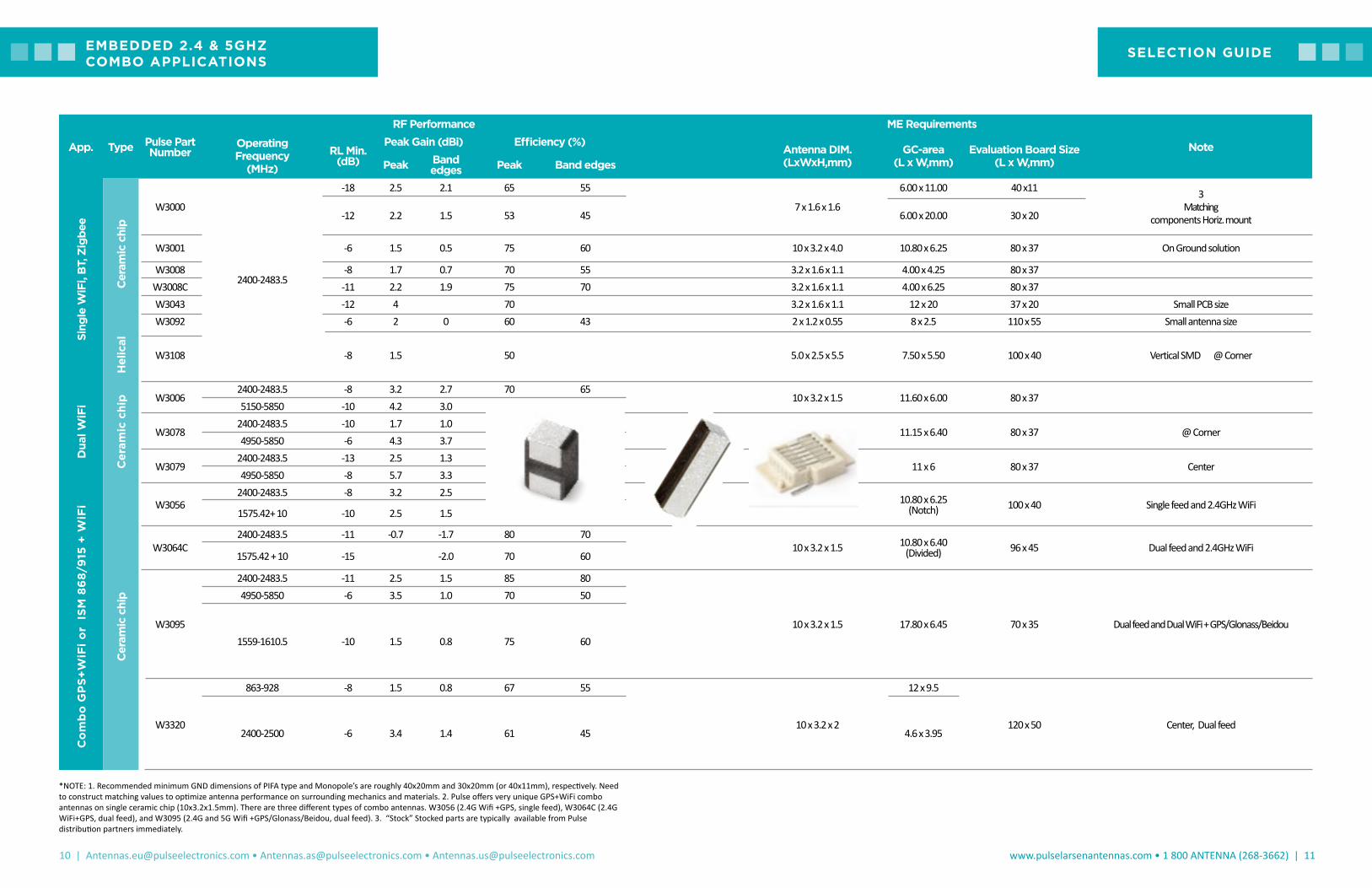
*NOTE: 1. Recommended minimum GND dimensions of PIFA type and Monopole’s are roughly 40x20mm and 30x20mm (or 40x11mm), respectively. Need to construct matching values to optimize antenna performance on surrounding mechanics and materials. 2. Pulse offers very unique GPS+WiFi combo antennas on single ceramic chip (10x3.2x1.5mm). There are three different types of combo antennas. W3056 (2.4G Wifi +GPS, single feed), W3064C (2.4G WiFi+GPS, dual feed), and W3095 (2.4G and 5G Wifi +GPS/Glonass/Beidou, dual feed). 3. “Stock” Stocked parts are typically available from Pulse distribution partners immediately.
App. Type Pulse Part Number
RF Performance ME Requirements
NoteOperating Frequency
(MHz)RL Min.
(dB)
Peak Gain (dBi) Efficiency (%)Antenna DIM. (LxWxH,mm)
GC-area (L x W,mm)
Evaluation Board Size (L x W,mm)Peak Band
edges Peak Band edges
Sing
le W
iFi,
BT,
Zig
bee
Cer
amic
chi
p
W3000
2400-2483.5
-18 2.5 2.1 65 55
7 x 1.6 x 1.6
6.00 x 11.00 40 x11 3 Matching
components Horiz. mount-12 2.2 1.5 53 45 6.00 x 20.00 30 x 20
W3001 -6 1.5 0.5 75 60 10 x 3.2 x 4.0 10.80 x 6.25 80 x 37 On Ground solution
W3008 -8 1.7 0.7 70 55 3.2 x 1.6 x 1.1 4.00 x 4.25 80 x 37W3008C -11 2.2 1.9 75 70 3.2 x 1.6 x 1.1 4.00 x 6.25 80 x 37W3043 -12 4 70 3.2 x 1.6 x 1.1 12 x 20 37 x 20 Small PCB sizeW3092 -6 2 0 60 43 2 x 1.2 x 0.55 8 x 2.5 110 x 55 Small antenna size
Hel
ical
W3108 -8 1.5 50 5.0 x 2.5 x 5.5 7.50 x 5.50 100 x 40 Vertical SMD @ Corner
Dua
l WiF
i
Cer
amic
chi
p W30062400-2483.5 -8 3.2 2.7 70 65
10 x 3.2 x 1.5 11.60 x 6.00 80 x 375150-5850 -10 4.2 3.0 80 70
W30782400-2483.5 -10 1.7 1.0 65 55
3.2 x 1.6 x 1.1 11.15 x 6.40 80 x 37 @ Corner4950-5850 -6 4.3 3.7 80 55
W30792400-2483.5 -13 2.5 1.3 72 60
3.2 x 1.6 x 1.1 11 x 6 80 x 37 Center4950-5850 -8 5.7 3.3 78 55
Co
mb
o G
PS
+W
iFi o
r I
SM
86
8/9
15 +
WiF
i
Cer
amic
chi
p
W30562400-2483.5 -8 3.2 2.5 80 70
10 x 3.2 x 1.5 10.80 x 6.25 (Notch) 100 x 40 Single feed and 2.4GHz WiFi
1575.42+ 10 -10 2.5 1.5 75 65
W3064C2400-2483.5 -11 -0.7 -1.7 80 70
10 x 3.2 x 1.5 10.80 x 6.40 (Divided) 96 x 45 Dual feed and 2.4GHz WiFi
1575.42 + 10 -15 -2.0 70 60
W3095
2400-2483.5 -11 2.5 1.5 85 80
10 x 3.2 x 1.5 17.80 x 6.45 70 x 35 Dual feed and Dual WiFi + GPS/Glonass/Beidou
4950-5850 -6 3.5 1.0 70 50
1559-1610.5 -10 1.5 0.8 75 60
W3320
863-928 -8 1.5 0.8 67 55
10 x 3.2 x 2
12 x 9.5
120 x 50 Center, Dual feed2400-2500 -6 3.4 1.4 61 45 4.6 x 3.95
SELECTION GUIDEEMBEDDED 2.4 & 5GHZ COMBO APPLICATIONS

12 | [email protected] • [email protected] • [email protected]
www.pulselarsenantennas.com • 1 800 ANTENNA (268-3662) | 13
App
.
Type Pulse Part
number
RF Performance ME Requirements
NoteOperating Frequency
(MHz)RL Min.
(dB)
RHCP Gain (dBic)
Linear Gain (dBi)
Efficiency (%)/(dB)
Antenna DIM. (LxWxH,mm)
GC-area (L x W,mm)
Evaluation Board Size (L x W,mm)Peak Band
edges Peak Band edges Peak Band
edges
GPS
Onl
y Cer
amic
chi
p W3000
1575.42 +/-10
-15 -3.9 -4.1 0.3 0 50/-3 45/-3.57 x 1.6 x 1.6
6 x 20 30 x 203 Matching components
-12 -3.5 -3.9 0.1 -0.2 50/-3 45/-3.5 6 x 11 40 x 11W3009 -11 0.2 -0.6 3 2.3 83/-0.8 70/-1.5 10 x 3.2 x 4.0 10.80 x 6.25 80 x 37 On Ground shunt 3.3pF
W3011 -12 0.85 0.5 3.4 3 85/-0.7 80/-1 3.2 x 1.6 x 1.1 4.00 x 4.25 80 x 37 w/o matching
Patc
h W3099 -14 3.5 - - - - - 25 x 25 x 4 - 70 x 70 AR: 3, V01; A
W3213 -13 -1.5 - - - - - 13 x 13 x 4 - 30 x 30 AR: 3, V02; C
Hel
ical
W3110 -16 -2.1 -2.4 1.3 0.7 47/-3.3 43/-3.7 5.0 x 2.5 x 5.5 7.50 x 5.50 100 x 40 Vertical SMD, @ Corner
GPS
, Glo
nass
, & B
eido
u
Cer
amic
chi
p
W3000
1559-1591 1575.42 +/-10
and 1598-1610
-18 -0.2 2.4 1.5 70/-1.55 65/-1.9 7 x 1.6 x 1.6 6 x 10 80 x 37 3 Matching components, Horiz. Mount + @Corner
W3010
-12 1 0 3 2.2 75/-1.25 70/-1.5
10 x 3.2 x 2 10.80 x 6.25 80 x 37
@ Position1 shunt 3.3pF
-12 1.5 0.4 3 1.8 70/-1.55 50/-3.0 @ Position2 shunt2.2pF
W3011A -16 1 -0.4 3.7 2.5 88/-0.6 70/-1.5 3.2 x 1.6 x 1.1 4.00 x 6.25 80 x 37 Shunt 1.8pFW3062A -10 0 -0.5 2.5 2.0 80/-1 60/-2.1 7 x 1.6 x 1.6 7.80 x 5.25 80 x 37 Shunt 2.2pF
Patc
h
W3216 -7 -2 - - - 60 50 13 x 13 x 5 - 50 x 50 Shunt 1.5pF V02; C
WiF
i and
GPS
Com
bo
Cer
amic
chi
p
W30562400-2483.5 -8 - - 3.2 2.5 80 70
10 x 3.2 x 1.5 10.80 x 6.25 (Notch) 100 x 40 Single feed and 2.4GHz +GPS
1575.42+ 10 -10 2.5 1.5 75 65
W3064C2400-2483.5 -11 - - -0.7 -1.7 80 70
10 x 3.2 x 1.5 10.80 x 6.40 (Divided) 96 x 45 Dual feed and 2.4GHz +GPS
1575.42 + 10 -15 -2.0 70 60
W3095
2400-2483.5 -10 - - 2.7 1.5 85 80
10 x 3.2 x 1.5 17.80 x 6.45 80 x 50 Dual feed and Dual WiFi + GPS/Glonass/Beidou4950-5850 -6 - - 3.7 1.0 73 53
1559-1610.5 -8 1.7 0.7 75 62
NOTE: 1. Recommended minimum GND dimensions of PIFA type and Monopole are roughly 40x20mm and 30x20mm (or 40x11mm), respectively. Need to construct matching values to optimize antenna performance on surrounding mechanics and materials. 2. Pulse offers very unique GPS+WiFi combo antennas on single ceramic chip (10x3.2x1.5mm). There are three different types of combo antennas. W3056 (2.4G Wifi +GPS, single feed), W3064C (2.4G WiFi+GPS, dual feed), and W3095 (2.4G and 5G Wifi +GPS/Glonass/Beidou, dual feed). 3. "Stock" Stocked parts are typically available from Pulse distribution partners immediately.
SELECTION GUIDEEMBEDDED GPS/GLONASS/BEIDOU APPLICATIONS

14 | [email protected] • [email protected] • [email protected]
www.pulselarsenantennas.com • 1 800 ANTENNA (268-3662) | 15
App Type Pulse Part Number
RF Performance ME Requirements
NoteFrequency Range (MHz)
RL Min. (dB)
Peak Gain (dBi) Efficiency (%)
Antenna DIM. (LxWxH,mm)
GC-area (L x W,mm)
Evaluation Board Size (L x W,mm)Peak Band edges Peak Band Edges
LTE
Co
mp
osi
te
W3796
698-960 -6 1.5 (Avg. peak gain) 65 (Avg.)
40 x 7 x 3 40.6 x 15 120 x 40.6
- Top mount: Horizontal
- Matching: SE3.3nH+SH0.7pF; SH6.8nH
1427.9-1660.9 -5.5 2 (Avg. peak gain) 55 (Avg.)1695-2200 -6 5.5 (Avg. peak gain) 75 (Avg.)
2300-2700 -6 5 (Avg. peak gain) 70 (Avg.)
Pent
a B
and
W3544A
824-960 -3.7 0.5 1.8 65 44
7.65 x 26 x 3 21 x 33.5 (W3544A) 110 x 50
1. Corner mount (vertical). 2.matching: *SE12nH
1710-1880 -4.6 2.9 2.3 74 451850-1990 -8.6 2.4 1.7 74 64
1920-2170 -5.6 2.2 1.1 68 60
W3544B
824-960 -6.5 1 -0.7 70 53
7.65 x 26 x 3 50 x 18 (W3544B) 110 x 50
1. Top mount (Horizontal)
2.matching: 10nH
1710-1880 -5.7 2.7 1.7 77 591850-1990 -9.3 2 1 77 69
1920-2170 -5 1.8 0.2 71 58
Qua
d ba
nd (
US)
Cer
amic
W3073
824-894 -4.7 0.4 -2.6 51 28
10 x 3.2 x 4 40 x 10 105 x 40
1. Matching: SE10nH+
SE12nH+SH12nH. 2.Tuning strip on PCB.
1710-1880 -3.5 2.3 0.7 59 401850-1990 -5.9 2.5 1.6 59 54
1920-2170 -3.3 2.2 0.9 58 46
Qua
d ba
nd
(EU
)
W3073
880-960 -3.8 1 -1.8 60 34
10 x 3.2 x 4 40 x 10 105 x 40
1. Matching: *SE10nH+
*SE10nH+*SH15nH.
2.Tuning strip on PCB.
1710-1880 -4.9 2.9 2 70 541850-1990 -8 2.9 2.5 71 62
1920-2170 -4.4 2.8 2.3 67 59
Dua
l ban
d
(EU
)
W3070
880-960 -5.1 1.2 -0.4 65 47
10 x 3.2 x 2 40 x 10 95 x 40
Matching: *SE18nH+ *SE10nH 1710-1880 -5.7 2.5 1.5 60 50
NOTE: 1. "Stock" Stocked parts are typically available from Pulse distribution partners immediately. 2. * SE = Series and *SH = Shunt
SELECTION GUIDEEMBEDDED FOR CELLULAR APPLICATIONS 2G/3G/4G/5G
16 | [email protected] • [email protected] • [email protected]
www.pulselarsenantennas.com • 1 800 ANTENNA (268-3662) | 17
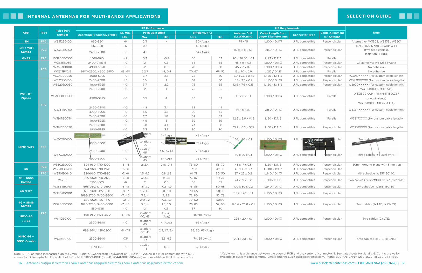
SELECTION GUIDEINTERNAL ANTENNAS FOR MULTI-BANDS APPLICATIONS
Note: 1. FPC antenna is measured on the 2mm PC plate. 2.Connector: Equivalent of I-PEX MHF 20278-11R-13 or compatible with U.FL connector. 3. Receptacle: Equivalent of I-PEX MHF 20279-001E (3pad), 20441-001E-01(4pad) or compatible with U.FL receptacles.
App. TypePulse Part Number
RF Performance ME RequirementsNote
Operating Frequency (MHz)RL Min.
(dB)Peak Gain (dBi) Efficiency (%) Antenna DIM.
(LxWxH,mm)Cable Length from
edge/ Diameter, mm Connector TypeCable Alignment
w/ AntennaMax. Min. Max. Min.ISM FPC W3312B0100 860-930 -8 2.3 - 50 (Avg.) 75 x 15 L:100 / D:1.13 U.FL compatible Perpendicular Alternative: W3502, W3538 , W3501
ISM + WiFi Combo
PCB W3332B0150863-928 -5 0.2 - 55 (Avg.)
82 x 15 x 0.56 L:150 / D:1.13 U.FL compatible PerpendicularISM 868/915 and 2.4GHz WiFi
(two feed cables). Isolation: <-11dB.
2400-2500 -10 4.1 - 64 (Avg.)
GNSS FPC W3908B0100 1560-1610 -12 0.3 -0.2 36 33 20 x 26.80 x 0.1 L:93 / D:1.13 U.FL compatible Parallel
WiFi, BT, Zigbee
PCB
W3525B039 2400-2483.5 -10 2 0.6 65 55 48 x 11 x 0.8 L:100 / D:1.13 U.FL compatible Perpendicular w/ adhesive: W3525BTWxxx
W3593B0100 4900-5850 -10 2 0.5 70 50 45 x 7 x 0.8 L:100 / D:1.13 U.FL compatible Perpendicular No adhesive
W3513B0212 2400-2500; 4900-5850 -13; -10 2;2.7 1.4; 0.4 70; 67 68; 52 16 x 70 x 0.9 L:212 / D:1.13 U.FL compatible Parallel No adhesive
W3919B0050 4900-5925 -10 3.7 2.5 72 50 15.9 x 7.6 x 0.45 L: 50 / D: 1.13 U.FL compatible Perpendicular W3919XXXXX (for custom cable length)
FPC
W3921B0100 2400-2500 -13 1.8 1 57 50 33 x 7.7 x 0.1 L: 100/ D:1.13 U.FL compatible Perpendicular W3921XXXXX (for custom cable length)
W3920B0050 4900-5925 -10 3.7 2.2 75 55 12.5 x 7.6 x 0.15 L: 50 / D: 1.13 U.FL compatible Perpendicular W3920XXXXX (for custom cable length)
W3315B0100MHF1
2400-2500 -10 2 1 75 65
45 x 6 x 0.1 L:100 / D:1.13 U.FL compatible Parallel
W3315B0100 (MHF-A13)
W3315B0100MHFIII (MHFIII 20367
or equivalent))
W3315B0100MHF4 (MHF4)
4900-5875 -10 5.5 4 85 62
W3334B01502400-2500 -10 4.8 3.4 53 49
14 x 5 x 0.1 L:150 / D:1.13 U.FL compatible Parallel W3334XXXXX (for custom cable length) 4900-5900 -10 5.5 3.5 90 65
W3917B00502400-2500 -10 2.7 1.8 62 53
42.6 x 8.6 x 0.15 L:50 / D:1.13 U.FL compatible Parallel W3917XXXX (for custom cable length) 4900-5925 -10 4.9 3 89 69
W3918B00502400-2500 -10 3.8 3.4 73 60
35.2 x 8.5 x 0.15 L:50 / D:1.13 U.FL compatible Perpendicular W3918XXXX (for custom cable length) 4900-5925 -10 5.3 3.3 90 70
MIMO WiFi FPC
W6102B01002400-2500 -10 isolation:
-20 2 (Avg.) 45 (Avg.)50 x 20 x 0.1 L:100 / D:1.13 U.FL compatible Perpendicular Two cables (2x Dual WiFi)
4900-5900 -10 isolation: -20 5 (Avg.) 75 (Avg.)
W6103B01002400-2500 -10 isolation:
-15 4.5 (Avg.) 70 (Avg.)80 x 20 x 0.1 L:100 / D:1.13 U.FL compatible Perpendicular Three cables (3x Dual WiFi)
4900-5900 -10 isolation: -15 5 (Avg.) 75 (Avg.)
3GPCB
W3502B0020 824-960; 1710-1990 -6; -4 2; 2.4 0.8; -0.4 78; 80 55; 70 43 x 17 x 0.5 L:20 / D:1.13 U.FL compatible Perpendicular 80mm ground plane with 5mm gap
W3538B0200 824-960; 1710-2170 -6; -6 - - 57; 71 41; 50 40 x 15 x 0.7 L:200 / D:1.13 U.FL compatible Perpendicular
FPC W3501B0140 824-960; 1710-1990 -7; -8 1.5; 4.2 0.8; 2.8 61; 71 50; 50 87 x 25 x 0.2 L:140 / D:1.13 U.FL compatible Perpendicular W/ adhesive: W3571B0140.
3G + GNSS Combo
FPC
W3915880-960; 1710-2170 -6; -8 3; 3.5 1; 2.8 73; 87 51; 75
74 x 19 x 0.2 L:100/ D:1.13 U.FL compatible Perpendicular Two cables (1x GSM900, 1x GPS/Glonass)1565-1605 -6 2 0.5 68 55
4G (LTE)W3554B0140 698-960; 1710-2690 -5; -8 1.5; 3.9 -0.6; 1.9 75; 86 50; 65 120 x 30 x 0.2 L:140 / D:1.13 U.FL compatible Perpendicular W/ adhesive: W3554B0140T
W3907B0100698-960; 1427-1610 -8; -7 2.2; 1.8 -0.5; 0 70; 65 50;50
115.7 x 20 x 0.1 L:100 / D:1.13 U.FL compatible Perpendicular1695-2700; 3400-3600 -7; -10 3.5; 4 1; 2.5 72; 80 52; 78
4G + GNSS Combo W3906B0100
698-960; 1427-1610 -13; -8 2.6; 2.2 -0.6; 1.2 70; 60 50;50
120.4 x 26.8 x 0.1 L:100 / D:1.13 U.FL compatible Perpendicular Two cables (1x LTE, 1x GNSS)1695-2700; 3400-3600 -7; -10 3.6; 4 1.8; 3.5 76; 85 52; 80
1550-1625 -10 2 0.5 37 30
MIMO 4G
(LTE)W6112B0100
698-960; 1428-2170 -6; -7.5isolation: -10; -15
4.3; 3.8 (Avg)
55; 68 (Avg.)224 x 20 x 0.1 L:100 / D:1.13 U.FL compatible Perpendicular Two cables (2x LTE)
2300-3600 -10 isolation: -15
4 (Avg.) 65 (Avg.)
MIMO 4G +
GNSS ComboW6113B0100
698-960; 1428-2200 -6; -7.5isolation: -10; -13
2.9; 1.7; 3.4 55; 60; 65 (Avg.)
224 x 20 x 0.1 L:100 / D:1.13 U.FL compatible Perpendicular Three cables (2x LTE, 1x GNSS)2300-3600 -7.5isolation:
-133.8; 4.2 70; 65 (Avg.)
1570-1610 -10isolation:
-130.8 35 (Avg.)
4.Cable length is a distance between the edge of PCB and the center of connector. 5. See datasheets for details. 6. Contact sales for available or custom cable lengths. Email: [email protected]. Phone: 800-ANTENNA (268-3662) or 360-944-7551.
18 | [email protected] • [email protected] • [email protected]
www.pulselarsenantennas.com • 1 800 ANTENNA (268-3662) | 19
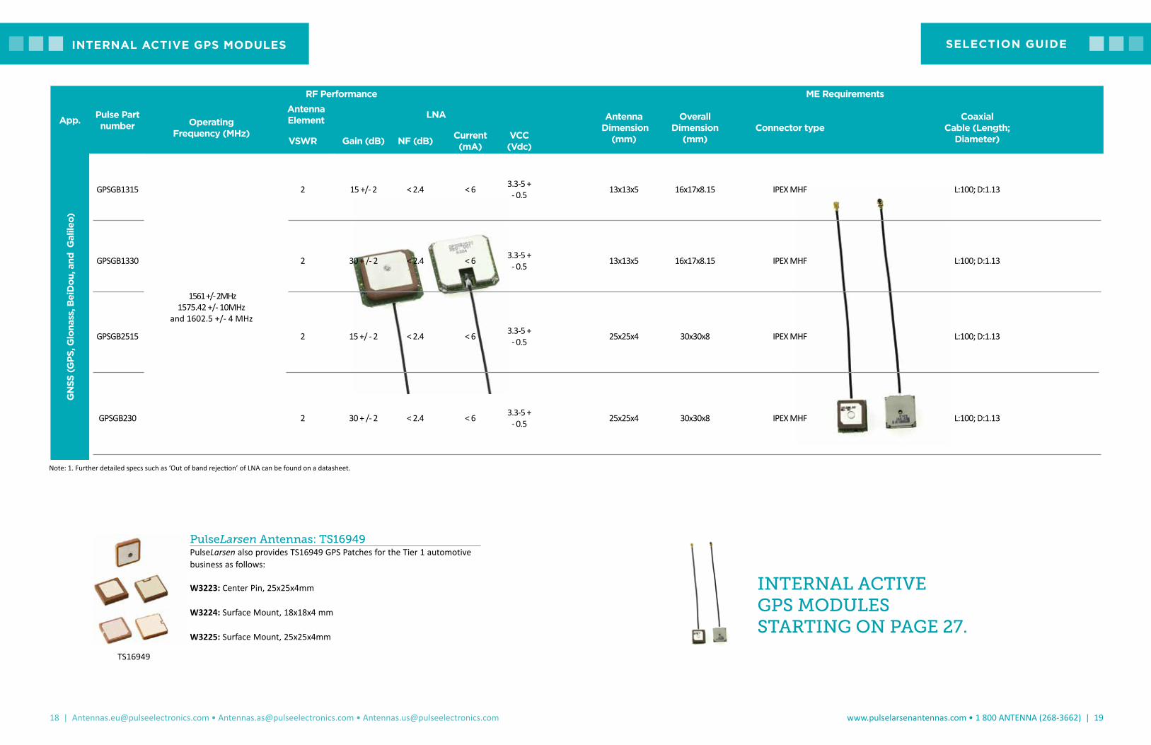
App. Pulse Part number
RF Performance ME Requirements
Operating Frequency (MHz)
Antenna Element LNA Antenna
Dimension (mm)
Overall Dimension
(mm)Connector type
Coaxial Cable (Length;
Diameter)VSWR Gain (dB) NF (dB) Current (mA)
VCC (Vdc)
GN
SS (G
PS, G
lona
ss, B
eiD
ou, a
nd G
alile
o)
GPSGB1315
1561 +/- 2MHz1575.42 +/- 10MHz
and 1602.5 +/- 4 MHz
2 15 +/- 2 < 2.4 < 6 3.3-5 + - 0.5 13x13x5 16x17x8.15 IPEX MHF L:100; D:1.13
GPSGB1330 2 30 + /- 2 < 2.4 < 6 3.3-5 + - 0.5 13x13x5 16x17x8.15 IPEX MHF L:100; D:1.13
GPSGB2515 2 15 +/ - 2 < 2.4 < 6 3.3-5 + - 0.5 25x25x4 30x30x8 IPEX MHF L:100; D:1.13
GPSGB230 2 30 + /- 2 < 2.4 < 6 3.3-5 + - 0.5 25x25x4 30x30x8 IPEX MHF L:100; D:1.13
SELECTION GUIDEINTERNAL ACTIVE GPS MODULES
Note: 1. Further detailed specs such as ‘Out of band rejection’ of LNA can be found on a datasheet.
INTERNAL ACTIVE GPS MODULES STARTING ON PAGE 27.
PulseLarsen Antennas: TS16949PulseLarsen also provides TS16949 GPS Patches for the Tier 1 automotive business as follows:
W3223: Center Pin, 25x25x4mm
W3224: Surface Mount, 18x18x4 mm
W3225: Surface Mount, 25x25x4mm
TS16949

20 | [email protected] • [email protected] • [email protected]
www.pulselarsenantennas.com • 1 800 ANTENNA (268-3662) | 21
App. TypePulse Part
number
RF Performance Mechanical Requirements
NoteFrequency
(MHz)
With matching network Without matching network (Bare coil)
Package type
Dimension (in/mm)
Reading distance
EMVCo (mm)
Reading Distance Grid Scan (Avg.,mm)
Impedance (Ω)
Self resonant frequency
(MHz)
Inductance (uH)
Resistance (Ω) Q-Factor
NFC
Flex
onl
y
W7001 13.56 40 33 50/80 100 0.9 1.55 49 A0.98 x 0.98 x 0.005
(25 x 25
x 0.12)Without a GND near antenna
Flex
wit
h Fe
rrit
e
W3579 13.56 40 28 50/80 42 1.6 3.60 37.8 B1.38 x 1.97 x 0.012
(50 x 50 x 0.30)
On GND solution
W7013 13.56 20 25 50/80 71.5 1.05 2.70 33 C 1.18 x 0.98 x 0.014 (30 x 25 x 0.36)
Flex
wit
h tw
iste
d p
air
cab
le +
co
nnec
tor
W7000 13.56 - 36 50 75.5 1.27 2.20 49 F 1.69 x 1.34 x 0.005 (43x 34 x 0.11)
Adhesive tape under coil included
Wir
e lo
op
on
pla
stic
car
rier
W7002 13.56 40 35 50/80 89 0.65 0.95 57 D3.72 x 2.24
x 0.14 (94.6 x 56.8
x 3.65)
Optimized for metal proximity within the device
WiF
i and
NFC
co
mb
o
Trac
e o
n P
CB W5100
13.56 - - 50 65.9 0.95 - 44
E1.57 x 1.57
x 0.05 (40 x 40 x 1.2)
Test setup over 80x80 mm metal GP2400-2483.5 RL Min. (dB): -8 Peak Gain in free space:
-1dBi Peak Gain on Metal: 1dBi -
W5101
13.56 - - 50 57.6 1.13 - 46
E1.77 x 1.77
x 0.05 (45 x 45 x 1.2)
Test setup over 80x80 mm metal GP2400-2483.5 RL Min. (dB): -8 Peak Gain in free space: 0.5dBi Peak Gain on Metal: 1.5dBi -
NOTE: 1. Wire assembly option: Picoblade connector with wire. 2. "Stock" Stocked parts are typically available from Pulse distribution partners immediately.
SELECTION GUIDEINTERNAL NFC APPLICATIONS
22 | [email protected] • [email protected] • [email protected]
www.pulselarsenantennas.com • 1 800 ANTENNA (268-3662) | 23
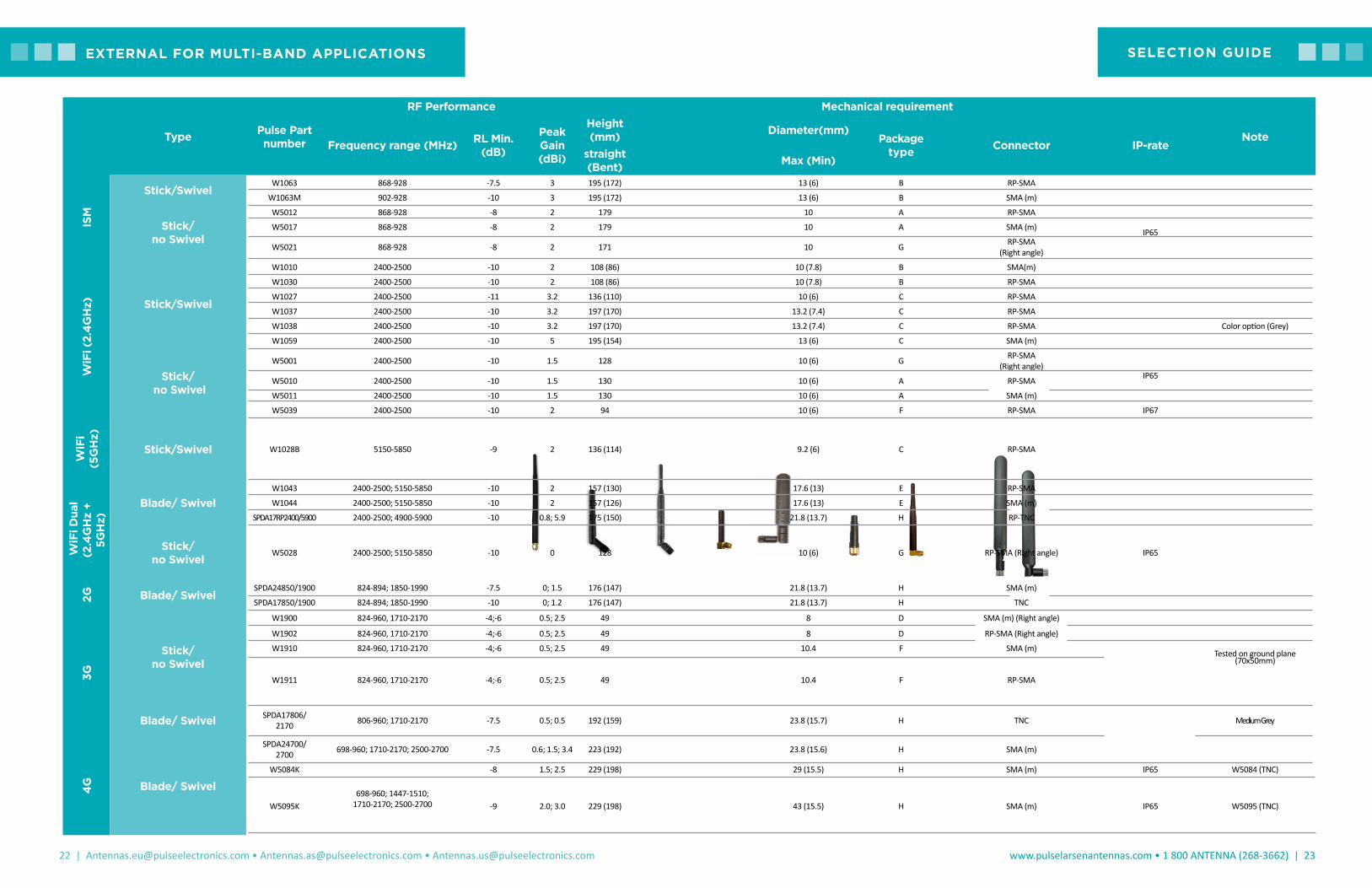
Type Pulse Part number
RF Performance Mechanical requirement
NoteFrequency range (MHz) RL Min.
(dB)
Peak Gain (dBi)
Height (mm) Diameter(mm)
Package type Connector IP-rate
straight (Bent) Max (Min)
ISM
Stick/SwivelW1063 868-928 -7.5 3 195 (172) 13 (6) B RP-SMA
W1063M 902-928 -10 3 195 (172) 13 (6) B SMA (m)
Stick/ no Swivel
W5012 868-928 -8 2 179 10 A RP-SMA
IP65W5017 868-928 -8 2 179 10 A SMA (m)
W5021 868-928 -8 2 171 10 G RP-SMA (Right angle)
WiF
i (2.
4G
Hz) Stick/Swivel
W1010 2400-2500 -10 2 108 (86) 10 (7.8) B SMA(m)
W1030 2400-2500 -10 2 108 (86) 10 (7.8) B RP-SMA
W1027 2400-2500 -11 3.2 136 (110) 10 (6) C RP-SMA
W1037 2400-2500 -10 3.2 197 (170) 13.2 (7.4) C RP-SMA
W1038 2400-2500 -10 3.2 197 (170) 13.2 (7.4) C RP-SMA Color option (Grey)
W1059 2400-2500 -10 5 195 (154) 13 (6) C SMA (m)
Stick/ no Swivel
W5001 2400-2500 -10 1.5 128 10 (6) G RP-SMA (Right angle)
IP65W5010 2400-2500 -10 1.5 130 10 (6) A RP-SMA
W5011 2400-2500 -10 1.5 130 10 (6) A SMA (m)
W5039 2400-2500 -10 2 94 10 (6) F RP-SMA IP67
WiF
i (5
GH
z)
Stick/Swivel W1028B 5150-5850 -9 2 136 (114) 9.2 (6) C RP-SMA
WiF
i Dua
l (2
.4G
Hz
+ 5G
Hz)
Blade/ SwivelW1043 2400-2500; 5150-5850 -10 2 157 (130) 17.6 (13) E RP-SMA
W1044 2400-2500; 5150-5850 -10 2 157 (126) 17.6 (13) E SMA (m)
SPDA17RP2400/5900 2400-2500; 4900-5900 -10 0.8; 5.9 175 (150) 21.8 (13.7) H RP-TNC
Stick/ no Swivel
W5028 2400-2500; 5150-5850 -10 0 128 10 (6) G RP-SMA (Right angle) IP65
2G Blade/ SwivelSPDA24850/1900 824-894; 1850-1990 -7.5 0; 1.5 176 (147) 21.8 (13.7) H SMA (m)
SPDA17850/1900 824-894; 1850-1990 -10 0; 1.2 176 (147) 21.8 (13.7) H TNC
3G
Stick/ no Swivel
W1900 824-960, 1710-2170 -4;-6 0.5; 2.5 49 8 D SMA (m) (Right angle)
Tested on ground plane (70x50mm)
W1902 824-960, 1710-2170 -4;-6 0.5; 2.5 49 8 D RP-SMA (Right angle)
W1910 824-960, 1710-2170 -4;-6 0.5; 2.5 49 10.4 F SMA (m)
W1911 824-960, 1710-2170 -4;-6 0.5; 2.5 49 10.4 F RP-SMA
Blade/ Swivel SPDA17806/2170 806-960; 1710-2170 -7.5 0.5; 0.5 192 (159) 23.8 (15.7) H TNC Medium Grey
4G Blade/ Swivel
SPDA24700/2700 698-960; 1710-2170; 2500-2700 -7.5 0.6; 1.5; 3.4 223 (192) 23.8 (15.6) H SMA (m)
W5084K
698-960; 1447-1510; 1710-2170; 2500-2700
-8 1.5; 2.5 229 (198) 29 (15.5) H SMA (m) IP65 W5084 (TNC)
W5095K -9 2.0; 3.0 229 (198) 43 (15.5) H SMA (m) IP65 W5095 (TNC)
SELECTION GUIDEEXTERNAL FOR MULTI-BAND APPLICATIONS

24 | [email protected] • [email protected] • [email protected]
www.pulselarsenantennas.com • 1 800 ANTENNA (268-3662) | 25
Pulse offers a wide range of surface mount antennas (SMD) for wireless device applications. Pulse ceramic technology results in robust antenna designs that have outstanding performance. These antennas have an inherent immunity to surrounding antenna signals and hand-effect, which makes them exceptionally suitable solutions for small hand-held or wall-mount devices with multiple antennas. Pulse helical antenna technology provides high-performance antennas in a small package that can be easily deployed. Our composite antennas offer the most frequency bands per embedded technology. These ceramic, helical, and composite antennas require minimal ground plane removal for operation, which means saved board space and economical implementation. The SMD compatibility of Pulse’s antenna products makes them simple and easy to mount.
EMBEDDED ONTO / SOLDERED TO PCB
• Antenna Technology: Ceramic monopoles, ceramic PIFA, ceramic patch, helical; stamped metal, composite.• Frequencies: WLAN(Wi-Fi), Zigbee, Bluetooth, ISM, GPS, 3G/4G LTE, Multi bands.• Applications: OEM equipment, medical devices, security systems, tracking and monitoring devices, handhelds, meter reading, smart devices, sensors, wearables, fitness, beacons, and more.
Helical Antennas
Ceramic Antennas
Ceramic Patch
Application Part No Size4 (mm)/Type
Mount Type3
(mm)Frequency
Range (MHz)RHCP Gain5
(dBic)Max Gain
(dBi)Efficiency(%/dB)
Return Loss
(dB MIN)
WiFi W300110x3.2x4mm
CeramicSMD, GC 10.8x6.25
2400 N/A 1.5 (peak) 75/-1.25 -6
WiFiDualband
W30793.2X1.6X1.1
Ceramic
SMD,GC area
11.00x6.00
2400–2483.55150–5850
N/A2.4 (peak)5.7 (peak)
72% (peak) 78% (peak)
-13 -8
WiFiDualband
W300610.0x3.2x1.5
Ceramic
SMD,GC area
11.60x6.002400–2483.5 N/A
3.2 (peak) 4.2 (peak)
70% (peak) 80% (peak)
-8 -10
Bluetooth/WiFi
W30922.0x1.2x0.55
Ceramic
SMD,GC area
8.00x2.502400–2483.5 N/A 2,2 (peak) 75/-1.3 (peak) -11
Bluetooth/WiFi
W3008C3.2x1.6x1.1
Ceramic
SMD,GC area
4.00x6.252400–2483.5 N/A 2,2 (peak) 75/-1.3 (peak) -11
GPS W300910.0x3.2x4.0
Ceramic
SMD,GC area
10.80x6.251575.42 ±10
0.7 (peak) 0.3 (band edges)
3 (peak) 80/-1.25 (peak) -10
ISM W301310x3.2x4 Ceramic
GC area 10.8x8.25
868-870 -- 1.5 65 -11
WiFi & GPS W305610x3.2x1.5
Ceramic
GC area 10.8x6.25
(Notch)
2400-2483.5 / 1575.42
-- 3.2 / 2.5 80 / 75 -8 / -10
WiFi & GPS W3064C10x3.2x1.5
Ceramic
GC area 10.8x6.4 (Divided)
2400-2483.5 / 1575.42
-- -0.7 / -1 80 / 70 -11 / -15
GPS W321313x13x4
Patch-- 1575.42 -1.5 -- -- -13
GPS W321613x13x5
Patch-- 1575.42 -2 -- 60 -7
GPS W3099 25x25x4 Patch -- 1575.42 3.5 -- -- -14
CERAMIC
1. All antennas are RoHS Compliant 2. Operating temperature -40°C to +85°C3. GC = Ground Clearance, mm
4. Length x Width x Height5. Monopole antenna performance is linked to different tuning circuit recommendations for the variety of applications. Consult the data sheet for more information
1. All antennas are RoHS Compliant 2. Operating temperature -40°C to +85°C3. GC = Ground Clearance, mm
4. Millimeters (mm)5. Monopole antenna performance is linked to different tuning circuit recommendations for the variety of applications. Consult the data sheet for more information
ANTENNAS FOR EMBEDDED SURFACE MOUNTING APPLICATIONS (continued)
CERAMIC (CONTINUED)
HELICAL
COMPOSITE
Application Part No. Size (mm)/Type
Mount Type3
(mm)
FrequencyRange (MHz)
RHCP Gain(dBic)
Max Gain(dBi)
Efficiency(%/dB)
Return Loss
(dB MIN)
GPS/Glonass & Beidou W3062A 7X1.6X1.6
Ceramic GC area 7.8x5.25 1559-1591 & 1598-1610 0 2.5 80 / -1 -10
Dual Band (EU) W3070 10x3.2x2 Ceramic GC area 40x10 880-960 /
1710-1880 -- 1.2 / 2.5 65 / 60 -5.1 / -5.7
Dual WiFi W3078 3.2x1.6x1.1 ceramic GC area 11.15x6.4 2400-2483.5 /
4950-5850 -- 1.7 / 4.3 65 / 80 -10 / -6
WiFi & GPS W3095 10x3.2x1.5 Ceramic GC area 17.8x6.45
2400-2483.5 / 4950-5850 / 1559-1610.5
-- 2.7/3.7/1.7 85/53/62 -10/-6/-8
ISM, or GPS, or GPS/Glonass/BD W30005
7x1.6x1.6 tuneable
monopoleSee
datasheet868-870; 1559-1591 & 1598-1610; 1575.4
See datasheet See datasheet See datasheet See
datasheet
GPS W3010 10.0x3.2x2.0 Ceramic
SMD,GC area 10.80x6.25 1575.42 ±10 -0,2 (peak) 2,8 (peak) 75/-1,25 (peak) -18
GPS W3011/A 3.2x1.6x1.1 Ceramic
SMD4x4.25/6.25 1575.42 ±10 0.85 (peak) 3.4 (peak) 85/-0.7 (peak) -12
ISM 900 W3012 10x3.2x4 Ceramic
SMDGC area 10.80x8.25 902-928 N/A 2 (peak) 70/- 1.55
(peak) -6
ISM 868/915 Monopole W30145 10x3.2x1.5
CeramicSMD
GC area 40x16848-888/895-935 N/A 1.55 (peak) 45/- 4.5 (peak) -6
Zigbee, ISMMonopole W30435 3.2x1.6x1.1
CeramicSMD
GC area, 17x202400, 1575 and other N/A 4 (peak) 70/-1.55 (peak) -12
ISM 868/985 2.4 BT/WiFi W3320 10x3.2x2.0
CeramicSMD
GC area, 9.8x8.8 868, 915,
2400 N/A 1.5 (peak)3.4 (peak)
66 / - (peak) 67 / - (peak)
-8-6
Application Part No Size (mm)/Type
Mount Type3
(mm)Frequency
Range (MHz)RHCP Gain
(dBic)Max Gain
(dBi)Efficiency(%/dB)
Return Loss(dB MIN)
WiFi W3108 5.0x2.5x5.5 Helical
SMD,GC area 7.50x5.50
2400–2483.5
N/A 1.5 50/-3 -8
GPS W3110 5.0x2.5x5.5 Helical
SMD,GC area 7.50x5.50
1575.42 ±10 -2,1 (peak)-2,4 (band
edges)
1,3 (peak)0,7 (band edges)
47/-3,3 (peak)43/-3,7 (band
edges)
-16
ISM W3112A 2.5x8.0x8.0 Helical
SMD,GC area 6.00x11.00 902–928 N/A 0.9 (peak)
-0.3 (band edges)67/-1.7 (peak)
50/-3 (band edges) -10
ISM W3113 12.4x8.0x2.5 Helical
SMD,GC area 8.00x40.00 902–928 N/A 0.8 (peak)
-0.3 (band edges)66 /-1.8 (peak)
51/-2.9(band edges) -10
ISM (315) W3126 35.35x9.90 Helical GC area 8x40 315 N/A -5 -- -10
ISM (433) W3127 35.35x9.90 Helical GC area 8x40 433-435 N/A -2.9 -- -15
Application Part No. Size (mm)/Type
Mount Type3
(mm)
FrequencyRange (MHz)
RHCP Gain
(dBic)
Max Gain(dBi)
Efficiency(%/dB)
Return Loss(dB MIN)
2G/3G W3544A/B 26x7.65x3 Composite SMD 824-960/1710-2170 N/A -1 50% -6 ave
2G/3G W3073 10x3.2x4 Composite SMD 824-894/1710-2170 or
880-960/1710-2170 N/A 2.9 50% -6 ave
3G / 4G LTE W3796 40 x 7 x 3 GC area 15 x 40 698 - 2700 N/A 1.5 / 2/ 5.5 55 / 70 -6
EMBEDDED ANTENNASEMBEDDED ANTENNAS
26 | [email protected] • [email protected] • [email protected]
www.pulselarsenantennas.com • 1 800 ANTENNA (268-3662) | 27
• Located inside the device.• Often connected by a short cable assembly to customer PCB.• Technology: Flexible printed circuit (FPC), PCB, Patch.• Frequencies: WLAN, Bluetooth, Zigbee, ISM, GPS, 3G/4G LTE, Multi bands.• Typical applications: Access points, industrial controls, utilities, Internet of Things, M2M, telemedicine, handheld devices, point-of-sale equipment, sensors, lighting, transportation and other devices.
PRINTED CIRCUIT BOARD ANTENNA SOLUTIONS
ANTENNAS FOR NEAR FIELD COMMUNICATIONS
Frequency(MHz)*
Part Number
Read Distance(mm)*
Size(mm)
SRF(MHz)**
Inductance(uH)**
Resistance(Ohms)**
Q ** Matched Q ***
13.56 W3579 40 35 x 50 x 0.30 42 1.6 3.6 37.8 5-30
13.56 W7001 40 25 x 25 x 0.12 100 0.9 1.55 49 5-30
13.56 W7002 40 94.6 x 56.8 x 3.65 89 0.65 0.95 57 5-30
13.56 W7013 20 25 x 30 x 0.23 - - - - -
Application Frequency Part Number
Mechanical Dimensions (in/Mm)
Cable Length (mm)/Connector Type
Gain(dBi)
Efficiency(%)
2G / 3G 850/900/1800/1900 W3501 0.98 x 3.43 x .008 25 x 87 x 0.2
56/I-PEX Connector 1.5 / 1.5 / 3.5 / 3.5 50 to 55 %
2G / 3G 850/900/1800/1901 W3502 1.69 x 0.67 x 0.0243 x 17 x 0.5
27.5/I-PEX Connector 2 / 1 / 1 / 2 40 to 60 %
WiFi 2.4 GHz W3525Bxxx 0.42 x 1.88 x .03110.7 x 47.7 x 0.8
Various cable lengths/I-PEX Connector 2 70%
WiFi 2.4 & 5 GHz W3513 0.63 x 2.76 x 0.0416 x 70 x 0.9
250/I-PEXConnector 2 50 to 72 %
WiFi 2.4 & 5 GHz W3315B0100 0.23 x 1.8in / 6x45 mm 100, I-PEX, MHF Series -3.5 / -2.5 70%
3G 4G LTE 698-960 / 1710-2170 / 2300-2700 W3554B0140 120 x 30 x 0.2 143 / I-PEX 2.5 60%
5 GHz Dipole 4900-5850 W3593B0100 45 x 7 x 0.8 109mm / I-PEX 2 50%
* With Matching Network** Coil Without Matching Network*** With Matching Network (adjustable range)
• Pulse can assist your engineering team to place/fix the antenna in the housing of the device. Antenna position, orientation, and cable routing can all impact the efficiency of the antenna inside the device.
• PCB-based antennas are best placed on flat surfaces for both physical and RF stability with the surrounding structure. Adhesives, slots, or snap-in features can be designed to hold antennas in place.
• FPC-based antennas are provided with adhesive tape for easy assembly in the device.
ANTENNA INTEGRATION
Part
NumberFrequency Impedance Size mm/inches SRF
Inductance (uH)
Q Factor
BlueTooth Gain, dBi
W510013.56 + 2400
(NFC + BT/WiFi)50
40x40x1.31.57x1.57x0.051
65.9 0.95 44 1.0
W510113.56 + 2400
(NFC + BT/WiFi)50
45x45x1.31.77x1.77x0.051
57.6 1.13 46 1.5
PAIRMATE ANTENNAS
Note: 1. Further detailed specs such as ‘Out of band rejection’ of LNA can be found on a datasheet.
PULSE INTERNAL ACTIVE ANTENNAS FOR GNSS (GPS/ GLONASS/BEIDOU, GALILEO) APPLICATIONS
App. TypePulse Part
Number
RF Performance ME requirement
Operating Frequency
(MHz)
Antenna Element LNA (low noise amplifier)
Antenna Dimension
(mm)
Overall Dimension
(mm)
Connector type
Coaxial Cable
(Length; Diameter)VSWR
RHCP Gain
(dBic)
Gain (dB)
NF (dB)
Current (mA)
VCC (Vdc)
GNSS (GPS,
Glonass, BeiDou,
and Galileo)
Active Module
GPSGB1315 1561 +/- 2, 1575.42 +/
- 10, and
1602 +/- 4 MHz
2:1 -1 + 1 15 + 2
< 2.4 < 6 3.3-5.0 +/- 0.5
13x13x5 16x17x8.15
IPEX MHF
L:100; D:1.13
GPSGB1330 2:2 -1 + 1 30 + 2 13x13x5 16x17x8.15 L:100; D:1.13
GPSGB2515 2:3 1 + 1 15 + 2 25x25x4 30x30x8 L:100; D:1.13
GPSGB2530 2:4 1 + 1 30 + 2 25x25x4 30x30x8 L:100; D:1.13
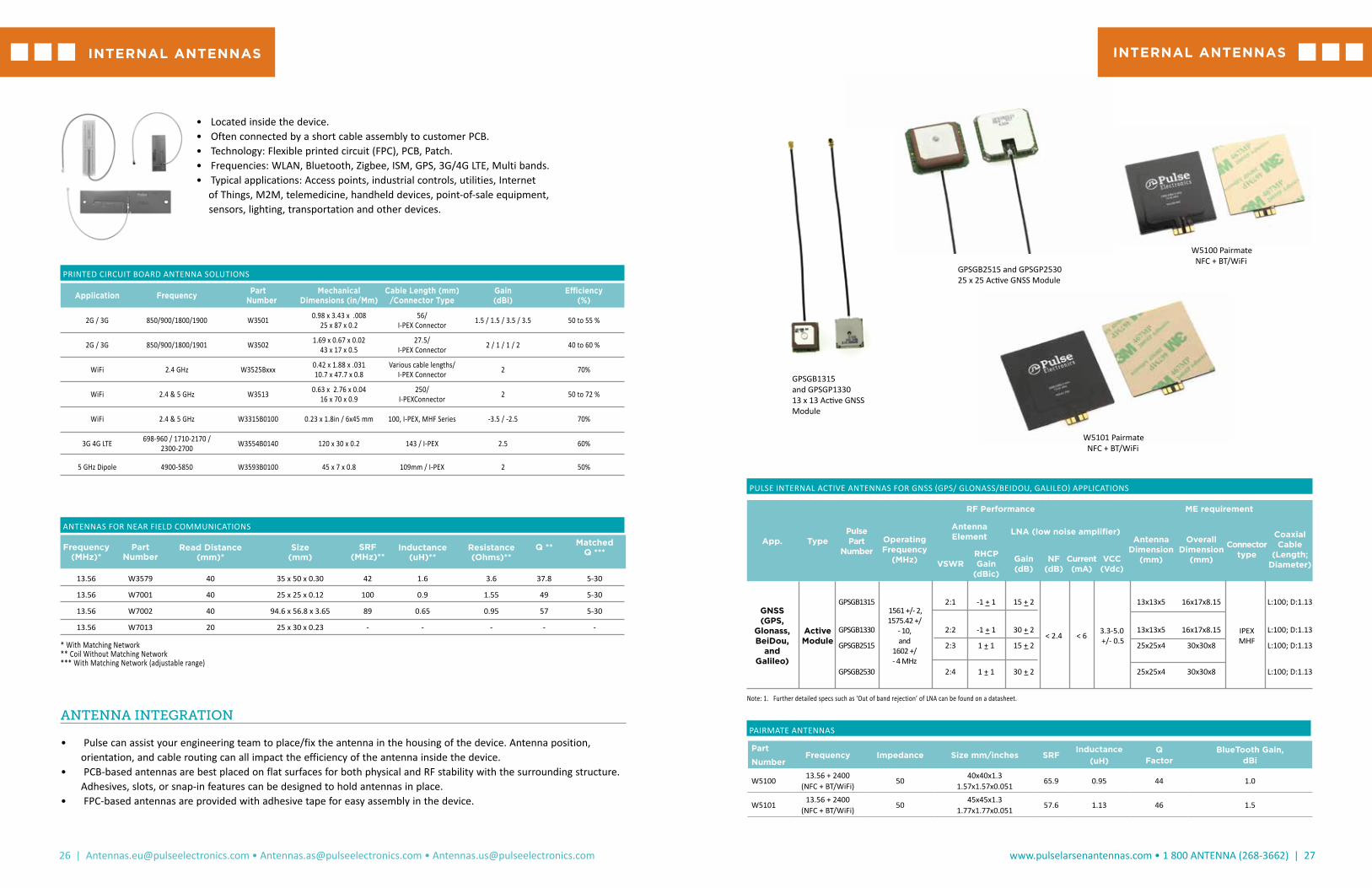
GPSGB1315 and GPSGP133013 x 13 Active GNSS Module
GPSGB2515 and GPSGP253025 x 25 Active GNSS Module
W5100 Pairmate NFC + BT/WiFi
W5101 Pairmate NFC + BT/WiFi
INTERNAL ANTENNASINTERNAL ANTENNAS
28 | [email protected] • [email protected] • [email protected]
www.pulselarsenantennas.com • 1 800 ANTENNA (268-3662) | 29
Model Frequency(MHz)
Gain (dBI)
Max Height(in) VSWR Connector
SPDA17RP2400/59002400-25004900-5900
2
5
6 (Bent)7 (Straight)
2.1 RPTNC
SPDA17806/2170LAR806-960
1710-2170.5
.5
6 (Bent)7.5 (Straight)
2.5:1 TNC
SPDA24700/2700698-960
1710-21702500-2700
6
1.5
3.4
7.7 (Bent)9 (Straight)
2.5:1 SMA Male
*W5084K 698-9601400-2690
2
4
7.8 (Bent)8.8 (Straight)
2.5:1 SMA Male*
*W5095K 698-9601400-2690
1.0
1.4
7.8 (Bent)8.8 (Straight)
2.5:1 SMA Male*
PRINTED CIRCUIT BOARD ANTENNA SOLUTIONS - MIMO AND MULTI-BAND
Application Type Pulse Part Number
RF Performance Mechanical Requirements
NoteOperating Frequency
(MHz)RL Min
(dB)Peak Gain (dBi Max)
Effi-ciency, Max %
Antenna DIM (LxWxH,mm) /
Coax Orientation
Cable Length from PCB edge/ Coax Diameter, mm)
Connector Type; / Adhesive
ISM WiFi Combo FPC W3312B0100 860-930 -8 2.3 50 (Avg) 75 x 15
Perpendicular L:100 / D:1.13 U.FL compatible / Adhesive Included
Alternative: W3502, W3538 , W3501
ISM WiFi Combo PCB W3332B0150
863-928 -5 0.2 55 (Avg)82 x 15 x 0.56
Perpendicular
L:150 / D:1.13 U.FL compatible / Adhesive Included
ISM 868/915 and 2.4GHz WiFi
(two feed cables). Isolation: <-11dB.2400-2500 -10 4.1 64 (Avg)
WiFi, BT, Zigbee
PCB
W3525B039 2400-2483.5 -10 2 65 48 x 11 x 0.8 Perpendicular L:100 / D:1.13 U.FL compatible /
Adhesive Not Incl.
W3593B0100 4900-5850 -10 2 70 45 x 7 x 0.8 Perpendicular L:100 / D:1.13 U.FL compatible /
Adhesive Not Incl.
W3513B02122400-2500 -13 2 70 16 x 70 x 0.9
Parallel L:212 / D:1.13 U.FL compatible /
Adhesive Included4900-5850 -10 2.7 67
FPC
W3921B0100 2400-2500 -13 1.8 57 33 x 7.7 x 0.1 Perpendicular L: 100/ D:1.13 U.FL compatible /
Adhesive IncludedW3921BXXXX
(for custom cable length)
W3315B0100MHF12400-2500 -10 2 75 45 x 6 x 0.1
Parallel
L:100 / D:1.13 U.FL compatible / Adhesive Included
W3315B0100 (MHF-A13)
W3315B0100MHFIII (MHFIII 20367)4900-5875 -10 5.5 85
W3334B01502400-2500 -10 4.8 53 14 x 5 x 0.1
Parallel
L:150 / D:1.13 U.FL compatible / Adhesive Included
4900-5900 -10 5.5 90
W3917B00502400-2500 -10 2.7 62 42.6 x 8.6 x 0.15
Parallel
L:50 / D:1.13 U.FL compatible / Adhesive Included
Parallel cable alignment. See W3917BXXXX (for custom cable length) 4900-5925 -10 4.9 89
W3918B00502400-2500 -10 3.8 73 35.2 x 8.5 x 0.15
Perpendicular
L:50 / D:1.13 U.FL compatible / Adhesive Included
Perpendicular cable alignment. See
W3918BXXXX(for custom cable length) 4900-5925 -10 5.3 90
MIMOWiFi
FPC W6102B01002400-2500 -10 2 (Avg.) 45 (Avg) 50 x 20 x 0.1
Perpendicular
L:100 / D:1.13 U.FL compatible / Adhesive Included Isolation: -20 dB
4900-5900 -10 5 (Avg.) 75 (Avg)
FPC W6103B01002400-2500 -10 4.5 (Avg.) 70 (Avg) 80 x 20 x 0.1
Perpendicular
L:100 / D:1.13 U.FL compatible / Adhesive Included Isolation: -15 dB
4900-5900 -10 5 (Avg.) 75 (Avg)
3G
PCB
W3502B0020824-960 -6 2 78 43 x 17 x 0.5
Perpendicular
L:20 / D:1.13 U.FL compatible / Adhesive Included
80mm ground plane with 5mm gap inside plastic
box1710-1990 -4 2.4 80.0
W3538B0200824-960 -6 - 57 40 x 15 x 0.7
Perpendicular
L:200 / D:1.13 U.FL compatible / Adhesive Included
1710-2170 -6 - 71
FPC
W3501B0140824-960 -7 1.5 61 87 x 25 x 0.2
Perpendicular
L:140 / D:1.13 U.FL compatible / Adhesive Not Incl.
Test unit : 150x100x40. With Adhesive: W3571B0140.1710-1990 -8 4.2 71.0
4G (LTE) W3554B0140
698-798 -5 1.5 75120 x 30 x 0.2
Perpendicular
L:140 / D:1.13 U.FL compatible / Adhesive Included
Connected on a test board 120x120 with 10mm gap824-960 -7 1.8 80
1710-2690 -8 3.9 86
MIMO 4G (LTE)
W6112B0100(2 leads)
698-960 -6 isolation: -10 55 (Avg)
224 x 20 x 0.1
PerpendicularL:100 / D:1.13 IPEX MHF 20278 or equiv.
/ Adhesive Included1428-2170 -7.5 isolation: -14 68 (Avg)
2300-3600 -10 isolation: -15 65 (Avg)
W6113B0100 (3 leads)
698-960
1428-2170
2300-3600
-6
-7.5
-10
isolation: -10
isolation: -14
isolation: -15
55 (Avg)
68 (Avg)
65 (Avg)
224 x 20 x 0.1
PerpendicularL:100 / D:1.13 IPEX MHF 20278 or equiv.
/ Adhesive Included GPS (1575MHZ)
Pulse’s new line of wireless access point antennas offers flexible and economical solutions for wireless device OEMs. These antennas offer superior transmission and reception between wireless access points. They are compatible with IEEE 802.11a/b/g/n/ac, Bluetooth, 3G/4G LTE, ZigBee and ISM frequency band applications. All wireless access point antennas are RoHS compliant. For high-volume orders, Pulse can custom design antennas for OEMs. This includes alternative frequencies and a variety of cable and connector options for antenna assemblies.
• Radome included - cosmetics may matter.• Not for outdoor weatherproof environments (not IP67)• Technology: Dipoles, blades, external patches.• Cable assemblies or connector options.• Frequencies: WLAN, 3G/4G LTE, ISM, GPS, Multi-bands.• Typical applications: Access points, industrial controls, utilities, Internet of Things, M2M, telemedicine, handheld devices, point-of- sale equipment, sensors, lighting, transportation and other devices.
Part Number Frequency Max Gain (dBI) Length (in/mm)
ApplicationStandard Connector
W1063 900 MHz 3.0 6.65 /169 ISM 868 & 915 MHz RP SMA
W10103 2.4 GHz 2.0 3.3/83 802.11b/g/n/ac, Bluetooth, ZigBee SMA Male
W1030 2.4 GHz 2.0 3.25/82.5 802.11b/g/n/ac, Bluetooth, ZigBee RP SMA
W1037 2.4 GHz 3.2 6.65/169 802.11b/g/n/ac, Bluetooth, ZigBee RP SMA
W1038 2.4 GHz 4.9 6.65/169 802.11b/g/n/ac, Bluetooth, ZigBee RP SMA
W1027 2.4 GHz 3.2 4.88/124 802.11b/g/n/ac, Bluetooth, ZigBee RP SMA
SB24003** 2.4 GHz 2.14 2.5/132 802.11b/g/n/ac, Bluetooth, ZigBeeRP SMA
W1043 2.4 & 5.8 GHz 2.0 4.59/117 802.11b/g/n/ac, Bluetooth, ZigBee
W1028B 5.15 & 5.85 GHz 2.0 4.88/124 802.11a/b/g/n/ac, ISM 5.8 GHz RP SMA
WIFI (WLAN) ANTENNAS1,2
WIFI AND LTE BROADBAND
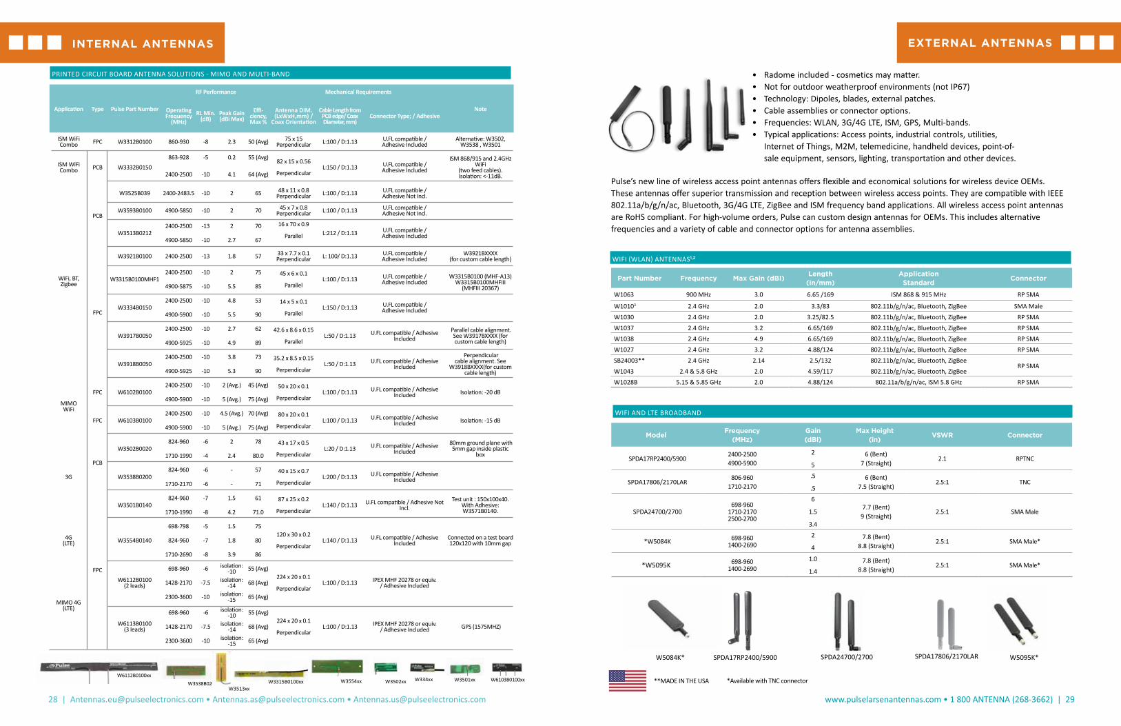
W3554xxW6112B0100xx
W3502xxW3538B0200xxW3513xx
W3315B0100xx W6103B0100xxW334xx W3501xx
EXTERNAL ANTENNASINTERNAL ANTENNAS
*Available with TNC connector
SPDA17806/2170LARSPDA17RP2400/5900 SPDA24700/2700W5084K* W5095K*
**MADE IN THE USA

30 | [email protected] • [email protected] • [email protected]
www.pulselarsenantennas.com • 1 800 ANTENNA (268-3662) | 31
Part Number Frequency Mechanical Length Cable Length Photo
W1049B030 2.4GHz 3.25/82.5 3/76
W1049B050 2.4GHz 3.25/82.5 5/127
W1049B090 2.4GHz 3.25/82.5 9/229
W1049B120 2.4GHz 3.25/82.5 12/305
Now Available: IceBlade Transparent Antennas• LTE Model with SMA : Pulse part : ICEBLADELS• LTE Model with TNC : Pulse part : ICEBLADELT• WiFi Model with SMA : Pulse part : ICEBLADEWS• WiFi Model with TNC : Pulse part : ICEBLADEWT
See PulseAntennas website for performance data.
Part Number Frequency(MHz)
Gain(dBi) Description Length
(in/mm)Coax Connector
SPDA24918 863-973 0 Swivel Mount Dipole (E) 8 / 202 N/A SMA Male
W1900; W1902824-960/ 1710-1990/ 1920-
21701 / 2 / 2.5 Penta Rt Angle Stubby (F) 2.1 / 49.5 N/A
SMA Male / RP-SMA Male
W1910; W1911824-960/ 1710-1990 / 1920-
21701 / 2 / 2.5 Penta Band Stubby (G) 2 / 49 N/A
SMA Male / RP-SMA Male
W4000G197 1.574 GHz 1.5 dBic / 26dB LNA GPS Ultra Thin (H) n/a 200 / 5meter SMA Male
SPDA17RP2400/5900 2400-2500 / 4900-5900 1.6 / 5 Swivel Mount Dipole (J) 7/182 N/A RPTNC
*SB450FME3 450-470 2.14 Stealth Blade (A) 10 / 254 3’ RG-174 FME
*SB8003 806-896 2.14 Stealth Blade (A) 2.5 / 132 3’ RG-174 No Conn
*SB9003 890-960 2.14 Stealth Blade (A) 2.5/132 3’ RG-174 No Conn
SPDA24850/1900 824-894/1850-1990 0/1.2 Swivel Mount Dipole (J) 6.75/171 N/A SMA
SPDA24700/2700698-960 / 1710-2710 / 2500-
2700.6/1.5/3.4 LTE Swivel Mount Dipole (J) 9 / 228 N/A SMA Male
*SPWB23150 136-174 -4.5 Wideband (D) 6.75 / 171 N/A SMA F T3
*SPWH23832 782-882 0 Whip, Standard, ¼ Wave (C) 3 / 76 N/A SMA F T3
*SPHS24832 800-864 0 Helical, Standard, ¼ Wave (B) 3 / 76 N/A SMA F T2
SPDA17806/2170LAR 806-960/1710-2170 .5/.5 Pentaband Swivel Mount Dipole (J) 7.5/190.5 N/A TNC Male
W1920G0915 806-960/1710-2170 1.5 Stealth Blade (A) 4.3/110 3’ RG-174 SMA Male
W1920G3658 806-960/1710-2170 1.5 Stealth Blade (A) 4.3/110 9’ RG-174 SMA Male
ADDITIONAL 3G/4G LTE, ISM, UHF, VHF, GPS, IP67
SINGLE-BAND EXTERNAL ANTENNAS WITH I-PEX
Pulse offers a wide variety of alternative wireless solutions for applications including machine-to-machine, public safety, hand-held radios, and telematics.
A. B. C. D. E. F. G. H. J.
ICE BLADE (IP67) (XXXX)
STEALTH BLADESStealth Blade antennas have the following specifications:
Gain: 2.14 dBiMaximum Power: 3 WattsPolarization: Linear
Frequency Bandwidth Dimensions Model (MHz) % @1.5/2.1 L x W (In) Coax Connector
SB698SMA3 698-960 / 1710-2170 / 2300-2700 50/60 4.2 x 1 3’ RG-316 SMA
SB698SMA12 698-960/1710-2170/2300-2700 50/60 4.2 x 1 12’ RG316 SMA
*SB8003 806-896 67/90 5.2 x .75 3’ RG-174 No Conn
*SB80012 806-896 67/90 5.2 x .75 12’ RG-174 No Conn
*SB800FME3 806-896 67/90 5.2 x .75 3’ RG-174 FME
*SB800FME12 806-896 67/90 5.2 x .75 12’ RG-174 FME
*SB800MPL3 806-896 67/90 5.2 x .75 3’ RG-174 MPL
*SB800MPL12 806-896 67/90 5.2 x .75 12’ RG-174 MPL
*SB800SMA3 806-896 67/90 5.2 x .75 3’ RG-174 SMA
*SB800TNC3 806-896 67/90 5.2 x .75 3’ RG-174 TNC
*SB800TNC12 806-896 67/90 5.2 x .75 12’ RG-174 TNC
*SB9003 890-960 67/90 5.2 x .75 3’ RG-174 No Conn
*SB90012 890-960 55/70 5.2 x .75 12’ RG-174 No Conn
*SB900SMA3 890-960 55/70 5.2 x .75 3’ RG-174 SMA
*SB900SMA12 890-960 55/70 5.2 x .75 12’ RG-174 SMA
*R380900323 806-960 / 1710-1990 5 X .8 10’ RG-174 FME
*R380900334 806-960 / 1710-1990 5 X .8 10’ RG-174 SMA
SB
R380
EXTERNAL ANTENNASEXTERNAL ANTENNAS
*MADE IN THE USA
*MADE IN THE USA
*MADE IN THE USA
WA700
MIMO LTE WALL MOUNT ANTENNA
Frequencies: 700-960 / 1710-1990 / 2110-2170 / 2500-2700 Low Band Gain: 2.5 dBI AverageHigh Band Gain: 3.5 dBi AveragePattern: Omni Directional
Part Number Cable TypeAntenna Size
(in/mm)
Cable Length(in/mm) Connector
WA700/2700SMA RG - 174 5.85 x 5 x 0.2 / 149 x 127 x 5.1
39.4 / 1000 SMA Male
WA700/2700RPSMA RG - 1745.85 x 5 x 0.2 / 149 x 127 x 5.1
39.4 / 1000 RP-SMA
Call us at +1.800.ANTENNA
Visit our website atpulselarsenantennas.com
Connect with us on twitterPulseLarsen1
PORTABLE RADIO ANTENNAS
32 | [email protected] • [email protected] • [email protected]
www.pulselarsenantennas.com • 1 800 ANTENNA (268-3662) | 33
The following chart summarizes performance, size and cost parameters for various antenna types.
ANTENNA PERFORMANCE CHART
Type Bandwidth Performance Length Connector Frequency Pricing
Helical Short 6% Poor (**) Short All VHF/UHF $$
Helical 8% Average (***) Shorter All Low/Mid/VHF/UHF $$
Helical Quarter Wave 12% Good (***) Longer All except SMA VHF $$
Whip 12% Good (***) Mid All UHF $
End Fed Half Wave 10% Better (****) Longer Coaxial 800 $$$
Half Wave Dipole 10% Best (*****) Longer Coaxial 800 $$$$
Wide Band 25% Good (***) Longer Coaxial All $$$$$
Dual Band 2x8% Average (***) Mid Coaxial VHF/UHF $$
Due to the high variability of use, measurements are difficult to make on portable antennas. All Larsen portable antenna designs are tested for gain and VSWR using a standard fixture for portable antennas. Gain measurements are determined based on range or chamber measurements. Performance ratings are determined using a VSWR standard of less than 2.0:1.
1/4-32x3/16KD2FREQHQ1 HQ Helical 1/4 λ 136 - 140 MHz 9 1/2”
KD2FREQHQ2 HQ Helical 1/4 λ 142 - 149 MHz 9 1/2”
KD2FREQHQ3 HQ Helical 1/4 λ 150 - 161 MHz 9 1/2”
KD2FREQHQ4 HQ Helical 1/4 λ 162 - 174 MHz 9 1/2”
TNC MALE KD3FREQHQ1 HQ Helical 1/4 λ 136 - 140 MHz 9 1/2”
KD3FREQHQ2 HQ Helical 1/4 λ 142 - 149 MHz 9 1/2”
KD3FREQHQ3 HQ Helical 1/4 λ 150 - 161 MHz 9 1/2”
KD3FREQHQ4 HQ Helical 1/4 λ 162 - 174 MHz 9 1/2”
KD3FREQHQ5 HQ Helical 1/4 λ 220 - 222 MHz 9 1/2”
KD13(freq) 1/4 λ 406 - 960 MHz 6”
TNCQ 1/4 λ 136 - 512 MHz Varies by freq
BNC MALE KD4UHF Helical 1/4 λ 406 - 512 MHz 3”
KD4VHF1 Helical 1/4 λ 136 - 141 MHz 8”
KD4VHF2 Helical 1/4 λ 142 - 149 MHz 8”
KD4VHF3 Helical 1/4 λ 150 - 161 MHz 8”
KD4VHF4 Helical 1/4 λ 162 - 174 MHz 8”
KD4FREQHQ1 HQ Helical 1/4 λ 136 - 140 MHz 9 1/2”
KD4FREQHQ2 HQ Helical 1/4 λ 142 - 149 MHz 9 1/2”
KD4FREQHQ3 HQ Helical 1/4 λ 150 - 161 MHz 9 1/2”
KD4FREQHQ4 HQ Helical 1/4 λ 162 - 174 MHz 9 1/2”
KD4150T Helical 1/4 λ 130 - 180 MHz Varies by freq
KD14(freq) 1/4 λ 406 - 960 MHz 6”
KD14FREQHW1 HW UHF 1/2 λ 315 - 409 MHz 16 1/2”
KD14FREQHW2 HW UHF 1/2 λ 416 - 504 MHz 16 1/2”
BNCQ 1/4 λ 136 - 512 MHz Varies by freq
All factory tuned KuLDUCKIES® are ExacTuned to your specified frequency. To order, replace the FREQ, UHF or VHF desig-nation with your desired center frequency.
Kulduckie®
PART ELECTRICAL FREQUENCY APPROX NUMBER TYPE BAND LENGTH
KuLDUCKIE® FREQUENCY COLOR CODE
VHF FREQUENCY COLOR UHF FREQUENCY COLOR
136 - 140 MHz Blue 406 - 420 MHz Black
142 - 149 MHz Green 450 - 469 MHz Black
150 - 160 MHz Yellow 470 - 512 MHz Black
162 - 174 MHz Red 150 / 450 MHz Blue
BNC
BNC Male coaxial connector unskirtedKD4/14
TNC
TNC Male coaxial connnector unskirted (TN type)KD3/13
1/4-32X3/16
Male stud type mount with skirt (MX type)KD2/12
PORTABLE RADIO ANTENNAS
ALL MADE IN THE USA

34 | [email protected] • [email protected] • [email protected]
www.pulselarsenantennas.com • 1 800 ANTENNA (268-3662) | 35
5/16-32Xx3/8 KD7FREQHQ1 HQ Helical 1/4 λ 136 - 140 MHz 9 1/2”
KD7FREQHQ2 HQ Helical 1/4 λ 142 - 149 MHz 9 1/2”
KD7FREQHQ3 HQ Helical 1/4 λ 150 - 161 MHz 9 1/2”
KD7FREQHQ4 HQ Helical 1/4 λ 162 - 174 MHz 9 1/2”
PL-259 KD9FREQHQ1 HQ Helical 1/4 λ 136 - 140 MHz 9 1/2”
KD9FREQHQ2 HQ Helical 1/4 λ 142 - 149 MHz 9 1/2”
KD9FREQHQ3 HQ Helical 1/4 λ 150 - 161 MHz 9 1/2”
KD9FREQHQ4 HQ Helical 1/4 λ 162 - 174 MHz 9 1/2”
KD19(freq) 1/4 λ 406 - 512 MHz 6”
PQ 1/4 λ 144 - 512 MHz Varies by freq
5/16-24 THDS FemaleKD22VHF1 Helical 1/4 λ 136 - 141 MHz 8”
KD22VHF2 Helical 1/4 λ 142 - 149 MHz 8”
KD22VHF3 Helical 1/4 λ 150 - 161 MHz 8”
KD22VHF4 Helical 1/4 λ 162 - 174 MHz 8”
KD22FREQHQ1 HQ Helical 1/4 λ 136 - 140 MHz 9 1/2”
KD22FREQHQ2 HQ Helical 1/4 λ 142 - 149 MHz 9 1/2”
KD22FREQHQ3 HQ vv 1/4 λ 150 - 161 MHz 9 1/2”
KD22FREQHQ4 HQ Helical 1/4 λ 162 - 174 MHz 9 1/2”
PART ELECTRICAL FREQUENCY APPROX NUMBER TYPE BAND LENGTH
5/16-32X3/8Male stud type mount (KR type)KD7
PL-259Standard UHF Connector MaleKD9/19
516-24THDS FemaleFemale threadedKD22
SPOTS!
SPOTS! CODE ANTENNA SELECTION GUIDE BY CONNECTOR TYPE
Determine connector type on the following pages and select the proper antenna based on frequency and type below. Field tunable antennas come with a cutting chart and cap to allow for tuning to exact frequency.
PART FREQUENCY APPROX NUMBER BAND (MHZ) ANTENNA TYPE LENGTH
SPHL10156 150 - 162 Helical Standard 1/4 λ 8”
SPHS10156 152 - 160 Helical Short 1/4 λ 4”
SPHL10160 154 - 166 Helical Standard - 1/4 λ 8”
SPHL10160IC* CC to 157 Helical Standard 1/4 λ 8”
SPHL10167 160 - 174 Helical Standard 1/4 λ 8”
SPHL10167IC* CC to 167 Helical Standard 1/4 λ 8”
SPWH10420 395 - 445 Whip Standard 1/4 λ 6”
SPHS10420 403 - 437 Helical Short 1/4 λ 3”
SPWH10450 425 - 475 Whip Standard 1/4 λ 6”
SPHS10450 432 - 468 Helical Short 1/4 λ 3”
SPWH10470 450 - 490 Whip Standard 1/4 λ 6”
SPHS10470 452 - 488 Helical Short 1/4 λ 3”
SPHL10FT Field Tunable 136 - 221 Helical Standard 1/4 λ 8”
SPWH10FT Field Tunable 400 - 512 Whip Standard 1/4 λ 6”
* This antenna is designed with a longer “skirt” for use with ICOM radios.
1/4-32X3/16 - MALE STUD CONNECTOR (MX TYPE)
1/4-32X3/16
Male stud type mount with skirt (MX type)
Popular Brands SupportedMotorola, Kenwood, Maxon, Midland, Wilson, G.E., Vertex
SPOTS! FREQUENCY COLOR CODE(SEE COLOR SPOT ON ANTENNA TOP)
VHF CENTER FREQUENCY COLOR 144 138 - 150 MHz Gray 156 150 - 162 MHz Orange 160 154 - 166 MHz Green 167 160 - 174 MHz Red
UHF CENTER FREQUENCY COLOR 420 403 - 437 MHz Blue 450 432 - 468 MHz Yellow 470 450 - 490 MHz Red 490 470 - 510 MHz Green
800 / 900 CENTER FREQUENCY COLOR 832 795 - 870 MHz Blue 918 872 - 964 MHz Red 1800 1710 - 1850 MHz Black 1900 1850 - 1990 MHz Black 2400 2400 - 2500 MHz Black
PORTABLE RADIO ANTENNASPORTABLE RADIO ANTENNAS ALL MADE IN THE USA ALL MADE IN THE USA

36 | [email protected] • [email protected] • [email protected]
www.pulselarsenantennas.com • 1 800 ANTENNA (268-3662) | 37
M7.0X1.0
Male stud type connector unskirted (MD type)
Popular Brands Supported
G.E., Ericsson
PART FREQUENCY APPROX NUMBER BAND (MHZ) ANTENNA TYPE LENGTH
*SPEN14832 806 - 866 Whip - 1/2 - End Fed 7”
*SPWH14832 782 - 882 Whip - Standard - 1/4 λ 3”
*SPHS14832 800 - 865 Helical - Short - 1/4 λ 2.75 ”
*SPEN14918 890 - 960 Half - End Fed 6”
*SPHL14FT Field Tunable 136 - 221 Helical - Standard - 1/4 λ 7”
M7 X 1.00 METRIC CONNECTOR (MD TYPE)
SPOTS!
PART FREQUENCY APPROX NUMBER BAND (MHZ) ANTENNA TYPE LENGTH
SPDA17806/2170LAR 806 - 960 / 1710 - 2170 Center Fed Dipole 8”
SPDA17832 824 - 894 Center Fed Dipole 8”
SPDA17850/1900 824 - 894 / 1850 - 1990 Center Fed Dipole 7.5”
SPDA17918 890 - 960 Center Fed Dipole 8”
SPDA171800 1710 - 1850 Center Fed Dipole 6.5”
SPDA171900 1850 - 1990 Center Fed Dipole 6.5”
SPDA172400 2400 - 2500 Center Fed Dipole 6”
SPDA17RP2400 2400 - 2500 Center Fed Dipole 6”
SPDA17RP2400/5900 2400 - 2500 / 4900 - 5900 Center Fed Dipole 6”
SPDA17RP918 890 - 960 Center Fed Dipole 8”
*SPHL17FT Field Tunable 136 - 221 Helical - Standard - 1/4 λ 8”
*SPWH17FT Field Tunable 400 - 512 Whip - Standard - 1/4 λ 6”
ICEBLADELT 698 - 960 / 1710 - 2170 / 2500 - 2700 Multiband 9”
ICEBLADEWT 698 - 960 / 1710 - 2170 / 2500 - 2700 Multiband 9”
TNC CONNECTOR - STANDARD (TN TYPE) - EXPOSED BRIGHT FINISH
TNC
TNC Male coaxial connnector unskirted (TN type)
Popular Brands Supported
Icom, Standard
BNC
BNC Male coaxial connector unskirted
Popular Brands Supported
G.E., Kenwood, Motorola, Maxon, Johnson
BNC-S
BNC Male coaxial connector fully skirted (BNX type)
Popular Brands Supported
Ericsson
PART FREQUENCY APPROX NUMBER BAND (MHZ) ANTENNA TYPE LENGTH
*SPHS15450 432 - 468 Helical - Short - 1/4 λ 3”
*SPHL15FT Field Tunable 136 - 221 Helical - Standard - 1/4 λ 8”
*SPWH15FT Field Tunable 400 - 512 Whip - Standard - 1/4 λ 6”
BNC CONNECTOR (BN TYPE)
PART FREQUENCY APPROX NUMBER BAND (MHZ) ANTENNA TYPE LENGTH
*SPHL16FT Field Tunable 136 - 221 Helical - Standard - 1/4 λ 8”
*SPWH16FT Field Tunable 400 - 512 Whip - Standard - 1/4 λ 6”
BNC CONNECTOR COVERED TYPE (BNX TYPE)
SPOTS!
SMA F T1
SMA Female flush insulator & partial skirt (SF Type)
Popular Brands Supported
Motorola
PART FREQUENCY APPROX NUMBER BAND (MHZ) ANTENNA TYPE LENGTH
SPWB21150 136 - 174 Helical - Standard - 1/4 λ 6.75”
SPHL21156 150 - 162 Helical - Standard - 1/4 λ 8”
SPHS21156 152 - 160 Helical - Short - 1/4 λ 4”
SPHL21167 160 - 174 Helical - Standard - 1/4 λ 8”
SPHS21167 162 - 172 Helical - Short - 1/4 λ 4”
SPWH21450 425 - 475 Whip - Standard - 1/4 λ 6”
SPHS21450 432 - 468 Helical - Short - 1/4 λ 3”
SPHS21490 475 - 512 Helical - Short - 1/4 λ 3”
SPWH21832 782 - 882 Whip - Standard - 1/4 λ 3”
SPHS21832 800 - 864 Helical - Short - 1/4 λ 2.75”
SPWH21918 863 - 973 Whip - Standard - 1/4 λ 3”
SPHS21918 872 - 954 Helical - Short - 1/4 λ 2.75”
SPHL21FT Field Tunable 136 - 221 Helical - Standard - 1/4 λ 8”
SPWH21FT Field Tunable 400 - 512 Whip - Standard - 1/4 λ 6”
SMA FEMALE - NON STANDARD MOTOROLA TYPE (SF TYPE)
PART FREQUENCY APPROX NUMBER BAND (MHZ) ANTENNA TYPE LENGTH
SPWH20832 782 - 882 Whip - Standard - 1/4 λ 3”
SPHS20832 800 - 864 Helical - Short - 1/4 λ 2.75”
SPWH20918 863 - 973 Whip - Standard - 1/4 λ 3”
SPHS20918 872 - 954 Helical - Short - 1/4 λ 2.75”
SPHL20FT Field Tunable 136 - 221 Helical - Standard - 1/4 λ 8”
SPWH20FT Field Tunable 400 - 512 Whip - Standard - 1/4 λ 6”
SMA MALE STANDARD - EXTENDED BASE - T1 (SMS TYPE)
SMA MALE T1
SMA Male extended base (SMS Type)
Popular Brands Supported
Standard
TNC-S
TNC Coaxial connector fully skirted (TNX type)
Popular Brands Supported
Vertex
PART FREQUENCY APPROX NUMBER BAND (MHZ) ANTENNA TYPE LENGTH
SPHL18FT Field Tunable 136 - 221 Helical - Standard - 1/4 λ 8”
SPWH18FT Field Tunable 400 - 512 Whip - Standard - 1/4 λ 6”
TNC CONNECTOR - COVERED (TNX TYPE)
PORTABLE RADIO ANTENNASPORTABLE RADIO ANTENNAS *MADE IN THE USA ALL MADE IN THE USA

38 | [email protected] • [email protected] • [email protected]
www.pulselarsenantennas.com • 1 800 ANTENNA (268-3662) | 39
SMA F T2
SMA Female recessed insulator & partial (short) skirt (SFJ type)
Popular Brands Supported
EF Johnson, Kenwood
PART FREQUENCY APPROX NUMBER BAND (MHZ) ANTENNA TYPE LENGTH
SPWB22150 136 - 174 Helical - Standard - 1/4 λ 6.75”
SPHL22156 150 - 162 Helical - Standard - 1/4 λ 8”
SPHL22167 160 - 174 Helical - Standard - 1/4 λ 8”
SPWH22450 425 - 475 Whip - Standard - 1/4 λ 6”
SPHS22450 432 - 468 Helical - Short - 1/4 λ 3”
SPWH22470 450 - 490 Whip - Standard - 1/4 λ 6”
SPHS22470 452 - 468 Helical - Short - 1/4 λ 3”
SPHS22490 475 - 512 Helical - Short - 1/4 λ 3”
SPWH22832 782 - 882 Whip - Standard - 1/4 λ 3”
SPHS22832 800 - 864 Helical - Short - 1/4 λ 2.75”
SPWH22918 863 - 973 Whip - Standard - 1/4 λ 3”
SPHS22918 872 - 954 Helical - Short - 1/4 λ 2.75”
SPHL22FT Field Tunable 136 - 221 Helical - Standard - 1/4 λ 8”
SPWH22FT Field Tunable 400 - 512 Whip - Standard - 1/4 λ 6”
SMA FEMALE STANDARD - FLUSH BASE - T2 (SFJ TYPE)
SPOTS!
SMA F T3
SMA Female recessed insulator & partial (long) skirt (SFU type)
Popular Brands Supported
Kenwood (2005 and newer models), Uniden, King
PART FREQUENCY APPROX NUMBER BAND (MHZ) ANTENNA TYPE LENGTH
SPWB23150 136 - 174 Helical - Standard - 1/4 λ 6.75”
SPHL23167 160 - 174 Helical - Standard - 1/4 λ 8”
SPWH23450 425 - 475 Whip - Standard - 1/4 λ 6”
SPHS23450 432 - 468 Helical - Short - 1/4 λ 3”
SPWH23470 450 - 490 Whip - Standard - 1/4 λ 6”
SPHS23470 452 - 488 Helical - Short - 1/4 λ 3”
SPWH23490 470 - 512 Whip - Standard - 1/4 λ 6”
SPHS23490 475 - 512 Helical - Short - 1/4 λ 3”
SPWH23832 782 - 882 Whip - Standard - 1/4 λ 3”
SPWH23918 863 - 973 Whip - Standard - 1/4 λ 3”
SPHS23918 872 - 954 Helical - Short - 1/4 λ 2.75”
SPHL23FT Field Tunable 136 - 221 Helical - Standard - 1/4 λ 8”
SPWH23FT Field Tunable 400 - 512 Whip - Standard - 1/4 λ 6”
SMA FEMALE STANDARD - HALF SKIRT BASE - T3 (SFU TYPE)
SPOTS!
SMA MALE T2
SMA Male flush base (SM Type)
Popular Brands
G.E., Technophone, Relm
PART FREQUENCY APPROXNUMBER CONNECTOR BAND (MHz) ANTENNA TYPE LENGTH
SPDA24700/2700 SMA Male 698-960/1710-2170/2500-2700 Multiband 9”
SPDA24832 SMA 824 - 894 Center Fed Dipole 9”
SPDA24850/1900 SMA 824 - 894 / 1850 - 1990 Center Fed Dipole 7.5”
SPDA24918 SMA M T2 890 - 960 Center Fed Dipole 8”
SPDA241800 SMA M T2 1710 - 1880 Center Fed Dipole 6.5”
SPDA241900 SMA M T2 1850 - 1990 Center Fed Dipole 6.5”
SPDA242400 SMA 2400 - 2500 Center Fed Dipole 6”
SPDA24RP918 SMA M T2 RP 890 - 960 Center Fed Dipole 8”
SPDA24RP 2400 SMA M T2 RP 2400 - 2500 Center Fed Dipole 6”
SPDP24832 SMA M T2 824 - 894 Center Fed Dipole 8”
SPDP24918 SMA M T2 890 - 960 Center Fed Dipole
SPDP242400 SMA M T2 2400 - 2500 Center Fed Dipole 3.5”
SPEN24815 SMA M T2 760 - 870 Whip - End Fed - 1/2 λ 7
*SPHS24832 SMA M T2 800 - 864 Helical - Short - 1/4 λ 2.75”
*SPHS24918 SMA M T2 872 - 954 Helical - Short - 1/4 λ 2.75”
*SPWB24150 SMA M T2 136 - 174 Wideband 7.5”
*SPWB24425 SMA M T2 380 - 470 Wideband 6.5”
*SPWB24480 SMA M T2 440 - 520 Wideband 6”
*SPWH24815 SMA M T2 760 - 870 Whip - Short - 1/4 Wave 3.5
*SPWH24918 SMA M T2 863 - 973 Whip - Standard - 1/4 λ 3”
*SPHL24FT SMA M T2 Field Tunable 136 - 221 Helical - Standard - 1/4 λ 8”
*SPWH24FT SMA M T2 Field Tunable 400 - 512 Whip - Standard - 1/4 λ 6”
ICEBLADELT SMA Male 698-960/1710-2170/2500-2700 Multiband 9”
ICEBLADEWS SMA Male 2400-2500/4900-5900 Multiband 9”
SMA MALE - FLUSH BASE - T2 (SM TYPE)
SPDA SPDP SPEN SPWH SPHLSPHS SPWB ICE
PORTABLE RADIO ANTENNASPORTABLE RADIO ANTENNAS ALL MADE IN THE USA
*MADE IN THE USA

40 | [email protected] • [email protected] • [email protected]
www.pulselarsenantennas.com • 1 800 ANTENNA (268-3662) | 41
The most commonly used cable assembly/mount is the NMOKHFUD (27 MHz to 6 GHz) with 17’ of UD (RG-58/U Dual Shield).
NOTE: Larsen springs (SPRING or SPRINGB) can be added to most mobile antennas.
LOW BAND COILS/WHIPS
Max Power Frequency Gain Height Rating Whip CableModel Type (MHz) (dBi) (In) (Watts) Color Assembly/Mount
NMO27BCO Loaded 1/4 λ 27-30 4 150 Coil Only Order Separately
NMO27B Loaded 1/4 λ 27-30 2 52.5 150 Black Order Separately
NMO27C Loaded 1/4 λ 27-30 2 52.5 150 Stainless Order Separately
NMO30BCO Loaded 1/4 λ 30-34 4 150 Coil Only Order Separately
NMO30B Loaded 1/4 λ 30-34 2 57.5 150 Black Order Separately
NMO30C Loaded 1/4 λ 30-34 2 57.5 150 Stainless Order Separately
NMO34BCO Loaded 1/4 λ 34-40 4 150 Coil Only Order Separately
NMO34B Loaded 1/4 λ 34-40 2 57.5 150 Black Order Separately
NMO34C Loaded 1/4 λ 34-40 2 57.5 150 Stainless Order Separately
NMO40BCO Loaded 1/4 λ 40-50 3.5 150 Coil Only Order Separately
NMO40B Loaded 1/4 λ 40-50 2 57.5 150 Black Order Separately
NMO40C Loaded 1/4 λ 40-50 2 57.5 150 Stainless Order Separately
NMOWB40C Loaded 1/4 λ 40-50 2 55 150 Stainless Order Separately
NMO50BCO Loaded 1/4 λ 47-54 3.5 150 Coil Only Order Separately
NMO50B Loaded 1/4 λ 47-54 2 52.5 150 Black Order Separately
NMO50C Loaded 1/4 λ 47-54 2 52.5 150 Stainless Order Separately
NMOQ52C 1/4 λ 52-88 2 55 150 Stainless Order Separately
NMOQ88C 1/4 λ 88-136 2 35 150 Stainless Order Separately
Q52 1/4 λ 52-88 2 55 200 Stainless Order Separately
Q88 1/4 λ 88-136 2 35 200 Stainless Order Separately
NMO Low Band
The most commonly used cable assembly/mount is the NMOKHFUD (27 MHz to 6 GHz) with 17’ of UD (RG-58/U Dual Shield).
NOTE: Larsen springs (SPRING or SPRINGB) can be added to most mobile antennas.
NMOQ Low Band NMOWB Low Band
Q Series Low Band
VHF COILS/WHIPS
Max Power Cable Frequency Gain Height Rating Whip Assembly/Model Type (MHz) (dBi) (In) (Watts) Color Mount Connector
MHW150BCO 1/2 λ 144-174 2.5 200 Coil Only Order Separately
MHW150C 1/2 λ 144-174 2 51.5 200 Stainless Order Separately
NMO150BCO 5/8 λ 144-174 2.5 200 Coil Only Order Separately
NMO150B 5/8 λ 144-174 5.14 51.5 200 Black Order Separately
NMO150C 5/8 λ 144-174 5.14 51.5 200 Stainless Order Separately
NMO150BK 5/8 λ 144-174 5.14 51.5 200 Black 17’ RG-58A/U PL-259
NMO150CK 5/8 λ 144-174 5.14 51.5 200 Stainless 17’ RG-58A/U PL-259
NMO150HWBCO 5/8 λ 144-174 2.5 200 Coil Only Order Separately
NMO150BHW 1/2 λ 144-174 2 51.5 200 Black Order Separately
NMO150CHW 1/2 λ 144-174 2 51.5 200 Stainless Order Separately
NMOU150D Loaded 1/4 λ 150-165 2 18 200 Black Order Separately
NMOU155D Loaded 1/4 λ 155-170 2 18 200 Stainless Order Separately
NMOWB150BCO Wideband 1/2 λ 135-174 2.75 100 Coil Only Order Separately
NMOWB150B Wideband 1/2 λ 135-174 2 51.75 100 Black Order Separately
NMOWB150C Wideband 1/2 λ 135-174 2 51.75 100 Stainless Order Separately
NMOWB150BK Wideband 1/2 λ 135-174 2 51.75 100 Black 17’ RG-58A/U PL-259
NMOWBQB* Wideband 1/4 λ 150-170 2 20 200 Black Order Separately
NMOWBQC* Wideband 1/4 λ 150-170 2 20 200 Stainless Order Separately
NMOQW144 1/4 λ 144-152 2 19 200 Stainless Order Separately
NMOQW152 1/4 λ 152-162 2 19 200 Stainless Order Separately
LM150BCO 5/8 λ 144-174 2.75 200 Coil Only Order Separately
LM150B 5/8 λ 144-174 51.75 200 Black Order Separately
LM150C 5/8 λ 144-174 51.75 200 Stainless Order Separately
LMWBQ Wideband 1/4 λ 150-170 2 18.5 200 Stainless Order Separately
LMWBQB Wideband 1/4 λ 150-170 2 18.5 200 Black Order Separately
PO150BCO 5/8 λ 144-174 2 2.5 200 Coil Only Order Separately
PO150B 5/8 λ 144-174 2 51.5 200 Black Order Separately
PO150C 5/8 λ 144-174 2 51.5 200 Black Order Separately
NMOQWNMOWBQNMO150 / NMOHW
LMLMWBMHW NMOWBNMOU
VHF 136-220 MHzLOW/MID BAND 27-136 MHz ALL MADE IN THE USA ALL MADE IN THE USA
Model TypeFrequency
(MHz)
Gain
(dBi)
Max
Height (in)
Power Ratings
(Watts)
Whip
Color
Cable
Assembly/Mount
Mount
Type
NMOWBPQB Wideband 1/4 λ 150-170 2 20 200 Black Order Separately NMO with Pogo Pin
NMOWBPQC Wideband 1/4 λ 150-170 2 20 200 Stainless Order Separately NMO with Pogo Pin
* NEW POGO PIN MODELS
Pogo Pin BasePO

42 | [email protected] • [email protected] • [email protected]
www.pulselarsenantennas.com • 1 800 ANTENNA (268-3662) | 43
The most commonly used cable assembly/mount is the NMOKHFUD (27 MHz to 6 GHz) with 17’ of UD (RG-58/U Dual Shield).
Glass Mount
VHF GLASS MOUNT
Max Power Cable Frequency Gain Height Rating Whip Assembly/Model Type (MHz) (dBi) (In) (Watts) Color Mount Connector
KGFFREQUDPL2 VHF Disguise 140-149 2 20 100 Black 14’ RG-58/U PL-259
KGFFREQUDPL3 VHF Disguise 150-159 2 20 100 Black 14’ RG-58/U PL-259
KGFFREQUDPL4 VHF Disguise 160-170 2 20 100 Black 14’ RG-58/U PL-259
KG144O/S 1/2 λ 144-160 2 48 100 Black Order Separately
KG144UD 1/2 λ 144-160 2 48 100 Black 14’ RG-58/U No Conn
KG144UDPL 1/2 λ 144-160 2 48 100 Black 14’ RG-58/U PL-259
KG160O/S 1/2 λ 160-174 2 47 100 Black Order Separately
KG160UD 1/2 λ 160-174 2 47 100 Black 14’ RG-58/U No Conn
KG160UDPL 1/2 λ 160-174 2 47 100 Black 14’ RG-58/U PL-259
KGVHFUDI/S Inside Cable Unit 144-174 100 14’ RG-58/U No Conn
VHF LOW PROFILE
Size Power Cable Frequency Gain H x DIA Rating Assembly/Model (MHz) (dBi) (In) (Watts) Color /Mount
LP152NMO 151.02-152.98 2 3.75 x 4.5 60 Black Order Separately
LP154NMO 152.96-155.04 2 3.75 x 4.5 60 Black Order Separately
LP156NMO 154.42-156.58 2 3.75 x 4.5 60 Black Order Separately
LP158NMO 156.38-158.62 2 3.75 x 4.5 60 Black Order Separately
LP160NMO 158.33-160.67 2 3.75 x 4.5 60 Black Order Separately
LP162NMO 160.29-162.71 2 3.75 x 4.5 60 Black Order Separately
LP164NMO 162.75-165.25 2 3.75 x 4.5 60 Black Order Separately
LP167NMO 165.21-167.79 2 3.75 x 4.5 60 Black Order Separately
LP169NMO 167.68-170.32 2 3.75 x 4.5 60 Black Order Separately
LP171NMO 170.16-172.84 2 3.75 x 4.5 60 Black Order Separately
LP174NMO 172.14-174.86 2 3.75 x 4.5 60 Black Order Separately
Low Profile
VHF MAGNETIC MOUNTS
Max Power Frequency Gain Height Rating Whip CableModel Type (MHz) (dBi) (In) (Watts) Color Assembly Connector
MSTFME Tunable 1/4 λ 144-965 2 21 50 Black 12’ RG-174 FME Crimp
VHF DIRECT MOUNTS
Max Power Frequency Gain Height Rating Whip CableModel Type (MHz) (dBi) (In) (Watts) Color Assembly Connector
OM150BCO 1/2 λ 144-174 3 200 Coil Only 17’ RB-58A/U PL-259
OM150CK 1/2 λ 144-174 2 51.75 200 Stainless 17’ RB-58A/U PL-259
PHW150BCO 1/2 λ 144-174 2 2.5 200 Coil Only Order Separately
PHW150C 1/2 λ 144-174 2 56.5 200 Stainless Order Separately
OM
MST
VHF 220 MHZ
Max Power Cable Frequency Gain Height Rating Whip Assembly/Model Type (MHz) (dBi) (In) (Watts) Color Mount
NMO220BCO 5/8 λ 220-225 5.2 2.5 200 Coil Only Order Separately
NMO220B 5/8 λ 220-225 5.2 30 200 Black Order Separately
NMO220C 5/8 λ 220-225 5.2 30 200 Stainless Order Separately
NMO220HWBCO 1/2 λ 220-225 3 200 Coil Only Order Separately
NMO220CHW 1/2 λ 220-225 2 30 200 Stainless Order Separately
NMOHW
The most commonly used cable assembly/mount is the NMOKHFUD (27 MHz to 6 GHz) with 17’ of UD (RG-58/U Dual Shield).
NOTE: Larsen springs (SPRING or SPRINGB) can be added to most mobile antennas.
PH
VHF 136-220 MHzVHF 136-220 MHz ALL MADE IN THE USA ALL MADE IN THE USA

44 | [email protected] • [email protected] • [email protected]
www.pulselarsenantennas.com • 1 800 ANTENNA (268-3662) | 45
The most commonly used cable assembly/mount is the NMOKHFUD (27 MHz to 6 GHz) with 17’ of UD (RG-58/U Dual Shield).
NOTE: Larsen springs (SPRING or SPRINGB) can be added to most mobile antennas.
UHF COILS/WHIPS
Max Power Frequency Gain Height Rating Whip CableModel Type (MHz) (dBi) (In) (Watts) Color Assembly
LMUHFBASEB Base Only 406-512 2 200 Coil Only Order Separately
LM406C 5/8 over 1/2 λ 406-420 5.6 33 200 Stainless Order Separately
LM440C 5/8 over 1/2 λ 440-460 5.6 33 200 Stainless Order Separately
LM450C 5/8 over 1/2 λ 450-470 5.6 33 200 Stainless Order Separately
NMO4063CS 5/8 λ 406-430 5.14 19 200 Stainless Order Separately
NMO4303CS 5/8 λ 430-450 5.14 19 200 Stainless Order Separately
NMO4503CS 5/8 λ 450-470 5.14 19 200 Stainless Order Separately
NMO4703CS 5/8 λ 470-490 5.14 19 200 Stainless Order Separately
NMO4903CS 5/8 λ 490-512 5.14 19 200 Stainless Order Separately
NMO406B 5/8 over 1/2 λ 406-420 5.6 33 200 Black Order Separately
NMO406C 5/8 over 1/2 λ 406-420 5.6 33 200 Stainless Order Separately
NMO420B 5/8 over 1/2 λ 420-440 5.6 33 200 Black Order Separately
NMO420C 5/8 over 1/2 λ 420-440 5.6 33 200 Stainless Order Separately
NMO440B 5/8 over 1/2 λ 440-460 5.6 33 200 Black Order Separately
NMO440C 5/8 over 1/2 λ 440-460 5.6 33 200 Stainless Order Separately
NMO450B 5/8 over 1/2 λ 450-470 5.6 33 200 Black Order Separately
NMO450C* 5/8 over 1/2 λ 450-475 5.6 33 200 Stainless Order Separately
NMO470C 5/8 over 1/2 λ 470-490 5.6 33 200 Stainless Order Separately
NMO490B 5/8 over 1/2 λ 490-512 5.6 33 200 Black Order Separately
NMO490C 5/8 over 1/2 λ 490-512 5.6 33 200 Stainless Order Separately
NMO406HWBCO Base Only 406-420 2.5 200 Coil Only Order Separately
NMO406CHW 1/2 λ Collinear 406-420 5.5 35.5 200 Stainless Order Separately
NMO420CHW 1/2 λ Collinear 420-440 5.5 35.5 200 Stainless Order Separately
NMO440CHW 1/2 λ Collinear 440-460 5.5 35.5 200 Stainless Order Separately
NMO450HWBCO Base Only 420-512 2.5 200 Coil Only Order Separately
NMO450CHW 1/2 λ Collinear 450-470 5.5 35.5 200 Stainless Order Separately
NMOQBASE1B Base Only Whip Size .070 2 200 Coil Only Order Separately
NMOQBASE2B Base Only Whip Size .100 2 200 Coil Only Order Separately
NMOQBASE3B Base Only Whip Size .125 2 200 Coil Only Order Separately
NMOUHBBASEB Base Only Whip Size .100 2 200 Coil Only Order Separately
NMOQW406 1/4 λ 406-430 2 7 200 Stainless Order Separately
NMOQW450 1/4 λ 450-470 2 7 200 Stainless Order Separately
NMOWB406BCO Wide Band Coil 406-512 2.5 200 Coil Only Order Separately
NMOWB406C Wide Band 406-430 5.5 35.5 200 Stainless Order Separately
NMOWB430C Wide Band 430-455 5.5 35.5 200 Stainless Order Separately
NMOWB450C Wide Band 450-475 5.5 35.5 200 Stainless Order Separately
NMOWB470C Wide Band 470-495 5.5 35.5 200 Stainless Order Separately
NMOWB490C Wide Band 490-515 5.5 35.5 200 Stainless Order Separately
LM
NMO CS
NMO400
NMOHW
NMOQW
NMOWB
UHF GLASS MOUNT
Max Power Cable Frequency Gain Height Rating Whip Assembly/Model Type (MHz) (dBi) (In) (Watts) Color Mount Connector
KG406O/S 1/2 λ 406-420 2 15 100 Black Order Separately
KG406UD 1/2 λ 406-420 2 15 100 Black 14’ RG-58/U No Conn
KG406UDPL 1/2 λ 406-420 2 15 100 Black 14’ RG-58/U PL-259
KG420O/S 1/2 λ 420-440 2 15 100 Black Order Separately
KG420UDPL 1/2 λ 420-440 2 15 100 Black 14’ RG-58/U PL-259
KG450O/S 1/2 λ 450-470 2 15 100 Black Order Separately
KG450UD 1/2 λ 450-470 2 15 100 Black 14’ RG-58/U No Conn
KG450UDPL 1/2 λ 450-470 2 15 100 Black 14’ RG-58/U PL-259
KG470O/S 1/2 λ 470-490 2 15 100 Black Order Separately
KG470UD 1/2 λ 470-490 2 15 100 Black 14’ RG-58/U No Conn
KG490O/S 1/2 λ 490-512 2 15 100 Black Order Separately
KG490UD 1/2 λ 490-512 2 15 100 Black 14’ RG-58/U No Conn
KGUHFUDI/S Inside Coupler Only 406-512 100 14’ RG-58/U No Conn
Glass Mount Inside
Coupler Outside
UHF LOW PROFILE
Size Power Cable Frequency Gain H x DIA Rating Assembly/Model (MHz) (dBi) (In) (Watts) Color /Mount
LP406NMO 406-420 1.5 x 4.5 100 Black Order Separately
LP406NMOW 406-420 2 1.5 x 4.5 100 Black Order Separately
LP420NMO 416-430 2 1.5 x 4.5 100 Black Order Separately
LP420NMOW 416-430 2 1.5 x 4.5 100 Black Order Separately
LP450NMO 450-470 2 1.5 x 4.5 100 Black Order Separately
LP450NMOW 450-470 2 1.5 x 4.5 100 Black Order Separately
LP470NMO 470-490 2 1.5 x 4.5 100 Black Order Separately
LP470NMOW 470-490 2 1.5 x 4.5 100 Black Order Separately
LP490NMO 490-512 2 1.5 x 4.5 100 Black Order Separately
LP490NMOW 490-512 2 1.5 x 4.5 100 Black Order Separately
LPT450NMO 450-470 2 4.5 x 1.5 100 Black Order Separately
LPT450/512NMO 450-520 4.6 3.5x1.5 100 Black Order Separately
LP LPT
The most commonly used cable assembly/mount is the NMOKHFUD (27 MHz to 6 GHz) with 17’ of UD (RG-58/U Dual Shield).
UHF 406-512 MHzUHF 406-512 MHz
LPT450/512NMO
ALL MADE IN THE USA ALL MADE IN THE USA
Model TypeFrequency
(MHz)
Gain
(dBi)
Max
Height (in)
Power Ratings
(Watts)
Whip
Color
Cable
Assembly/Mount
Mount
Type
NMOP450C 5/8 over 1/2 λ 450-475 5.6 33 200 Stainless Order Separately NMO with Pogo Pin
* NEW POGO PIN MODELS
Pogo Pin Base

46 | [email protected] • [email protected] • [email protected]
www.pulselarsenantennas.com • 1 800 ANTENNA (268-3662) | 47
Model TypeFrequency
(MHz)
Gain
(dBi)
Max
Height (in)
Power Ratings
(Watts)
Whip
Color
Cable
Assembly/Mount
Mount
Type
NMOP2/70SHVHF: Center LoadedUHF: Center Loaded
3/4 λ 1/2 λ
144-148 440-450
2.14 4
19 200 Stainless Order Separately NMO with Pogo Pin
NMOP150/450/800 Tri Band150-165 / 450-470 / 806-940
2.14 16.5 100 Black Order Separately NMO with Pogo Pin
UHF MAGNETIC MOUNTS
Max Power Frequency Gain Height Rating Whip CableModel Type (MHz) (dBi) (In) (Watts) Color Assembly Connector
MSTFME Tunable 1/4 λ 144-965 2 21 50 Black 12’ RG-174 FME Crimp
MSTBNCFT Tunable 1/4 λ 144-965 2 21 50 Black 12’ RG-174 TNCMST
UHF STEALTH BLADES
Stealth Blade antennas hava a gain of 2.14 dBi, a maximum power of 3 Watts and linear polarization.
Frequency Bandwidth Dimensions Model (MHz) % @1.5/2:1 L x W (In) Coax Connector
SB450FME12 450-470 20/30 10” x 0.75” 12’ RG-316 FME
SB
UHF DIRECT MOUNTS
Power Frequency Gain Size Rating Whip CableModel Type (MHz) (dBi) (In) (Watts) Color Assembly Connector
LP450 Low Profile 450-470 2 1.25H x 5.25D 100 N/A 17’ RG-58/U No Conn
OM406BCO 1/2 λ 406-440 4 100 Coil Only 17’ RG-58A/U PL259
OM450BCO 1/2 λ 440-512 4 100 Coil Only 17’ RG-58A/U PL259
OM406CK 1/2 λ Collinear 406-420 5.5 35.5 100 Stainless 17’ RG-58A/U PL259
OM420CK 1/2 λ Collinear 420-440 5.5 35.5 100 Stainless 17’ RG-58A/U PL259
OM450CK 1/2 λ Collinear 450-470 5.5 35.5 100 Stainless 17’ RG-58A/U PL259
OM470CK 1/2 λ Collinear 470-490 5.5 35.5 100 Stainless 17’ RG-58A/U PL259
LP Direct Mount OM
MULTI BAND VHF/UHF GLASS MOUNT
Max Power Frequency Gain Height Rating Whip CableModel Type (MHz) (dBi) (in) (Watts) Color Assembly Connector
KG2/70CXPL 1/2 λ Collinear 144-148 / 442-448 2 32.75 100 Black 14’ RG-58A/U PL-259
KG2/70CXFME 1/2 λ Collinear 144-148 / 442-448 2 32.75 100 Black 14’ RG-58A/U FME
MULTI BAND VHF/UHF MAGNETIC MOUNTS
Max Power Frequency Gain Height Rating Whip CableModel Type (MHz) (dBi) (in) (Watts) Color Assembly Connector
MM2/70PL VHF: Center Loaded 1/4 λ 144-148 2 21 50 Black 12’ RG-58A/U PL-259 UHF: Center Loaded 3/4 λ 442-448 4
MM2/70
KG2/70
NMO2/70
NMO150/450C
NMO2/70SH
NMO150/450/800
The most commonly used cable assembly/mount is the NMOKHFUD (27 MHz to 6 GHz) with 17’ of UD (RG-58/U Dual Shield).
MULTI BAND COILS/WHIPS
Max Power Frequency Gain Height Rating Whip CableModel Type (MHz) (dBi) (in) (Watts) Color Assembly
NMO2/70BCO Dual Band Coil 144-148 / 440-450 100 Coil Only Order Separately
NMO2/70B VHF: Center Loaded 1/2 λ 144-148 3.8 34.5 100 Black Order Separately
UHF: Collinear 440-450 5.2
NMO2/70SH* VHF: Center Loaded 1/2 λ 144-148 2.14 19 200 Stainless Order Separately
UHF: Center Loaded 3/4 λ 440-450 4
NMO150/450C VHF: Center Loaded 1/2 λ 150-154 3.8 37.25 100 Stainless Order Separately
UHF: Collinear 450-460 5.2
NMO150/450/800* Tri Band 150-165 / 450-470 / 806-940 2.14 16.5 100 Black Order Separately
MULTI BAND VHF/UHFUHF 406-512 MHz ALL MADE IN THE USA ALL MADE IN THE USA
* NEW POGO PIN MODELS
Pogo Pin Base

48 | [email protected] • [email protected] • [email protected]
www.pulselarsenantennas.com • 1 800 ANTENNA (268-3662) | 49
TUNABLE 1/4 WAVE COILS/WHIPS
Max Power Frequency Gain Height Rating Whip CableModel (MHz) (dBi) (In) (Watts) Color Assembly
NMOQSPEC 136-960 2 22 200 Stainless Order Separately
NMOQSPECB 136-960 2 22 200 Black Order Separately
NMOQC 136-512 2 23 200 Stainless Order Separately
NMOQB 136-512 2 23 200 Black Order Separately
PQ 136-512 2 22 200 Stainless Order Separately
Q 136-512 2 22 200 Stainless Order Separately
QB 136-512 2 22 200 Black Order Separately
TUNABLE 1/4 WAVE MAGNETIC MOUNTS
Max Power Frequency Gain Height Rating Whip CableModel (MHz) (dBi) (In) (Watts) Color Assembly Connector
MSTFME 144-965 2 21 50 Black 12’ RG-174 FME CrimpMST
NMOQSPEC
NMOQ
PQ
Q
The most commonly used cable assembly/mount is the NMOKHFUD (27 MHz to 6 GHz) with 17’ of UD (RG-58/U Dual Shield).
700/800/900/1850 MHZ COILS/WHIPS
Max Power Frequency Gain Height Rating Whip Cable AssemblyModel Type (MHz) (dBi) (In) (Watts) Color and Connector
LM800 5/8 over 1/2 λ 806-866 5.6 14.5 200 Stainless Order Separately
LM825 5/8 over 1/2 λ 824-896 5.6 14.5 200 Stainless Order Separately
LM900 5/8 over 1/2 λ 890-960 5.6 14.5 200 Stainless Order Separately
NMOQW700 1/4 λ 740-806 2 3 200 Stainless Order Separately
NMOQW800 1/4 λ 806-896 2 3 200 Stainless Order Separately
NMOQW900 1/4 λ 890-970 2 3 200 Stainless Order Separately
NMOQSPEC800B 1/4 λ 806-896 2 4 200 Black Order Separately
NMOQSPEC900B 1/4 λ 890-970 2 4 200 Black Order Separately
NMOQ700B 1/4 λ 740-806 2 4.5 200 Black Order Separately
NMOQ800B 1/4 λ 806-896 2 4.5 200 Black Order Separately
NMOQ900B 1/4 λ 890-960 2 4.5 200 Black Order Separately
NMOSPEC800 5/8 over 1/4 λ 806-866 5.4 13.5 200 Stainless Order Separately
NMOSPEC825 5/8 over 1/4 λ 824-896 5.4 13.5 200 Stainless Order Separately
NMOSPEC900 5/8 over 1/4 λ 890-960 5.4 13.5 200 Stainless Order Separately
NMO3HD800B 5/8 over 1/4 λ 806-866 5.4 13.75 200 Black Order Separately
NMO3HD825B 5/8 over 1/4 λ 824-896 5.4 13.75 200 Black Order Separately
NMO3HD900B 5/8 over 1/4 λ 890-960 5.4 13.75 200 Black Order Separately
NMO3E700B 5/8 over 1/4 λ 740-806 5.4 13.5 200 Black Order Separately
NMO3E800B 5/8 over 1/4 λ 806-866 5.4 13.5 200 Black Order Separately
NMO3E825B 5/8 over 1/4 λ 824-896 5.4 13.5 200 Black Order Separately
NMO3E900B 5/8 over 1/4 λ 890-960 5.4 13.5 200 Black Order Separately
NMO700 5/8 over 1/2 λ 740-806 5.6 12.75 200 Stainless Order Separately
NMO800 5/8 over 1/2 λ 806-866 5.6 12.75 200 Stainless Order Separately
NMO825 5/8 over 1/2 λ 824-896 5.6 12.75 200 Stainless Order Separately
NMO900 5/8 over 1/2 λ 890-960 5.6 12.75 200 Stainless Order Separately
NMO800B 5/8 over 1/2 λ 806-866 5.6 12.75 200 Black Order Separately
NMO825B 5/8 over 1/2 λ 824-896 5.6 12.75 200 Black Order Separately
NMO900B 5/8 over 1/2 λ 890-960 5.6 12.75 200 Black Order Separately
NMO5T800B 5/8 over 5/8 over 1/4 λ 806-866 7.2 18 200 Black Order Separately
NMO5T825B 5/8 over 5/8 over 1/4 λ 824-896 7.2 18 200 Black Order Separately
NMO5T900B* 5/8 over 5/8 over 1/4 λ 890-960 7.2 18 200 Black Order Separately
NMO5E825B 5/8 over 5/8 over 1/4 λ 824-896 7.2 19 200 Black Order Separately
NMO5E900B 5/8 over 5/8 over 1/4 λ 890-960 7.2 19 200 Black Order Separately
Q800 1/4 λ 806-866 2 3.5 200 Stainless Order Separately
Q900 1/4 λ 890-960 2 3.5 200 Stainless Order Separately
The most commonly used cable assembly/mount is the NMOKHFUD (27 MHz to 6 GHz) with 17’of UD (RG-58/U Dual Shield).
LMNMO3HD
NMO5T
NMOSPEC
NMOQW
NMO5E NMO3E
NMOQSPEC
700/800/900/1850 MHzTUNABLE 1/4 WAVE 136-960 MHz ALL MADE IN THE USA ALL MADE IN THE USA
Model TypeFrequency
(MHz)
Gain
(dBi)
Max
Height (in)
Power Ratings
(Watts)
Whip
Color
Cable
Assembly/Mount
Mount
Type
NMOP5T900B 5/8 over 5/8 over 1/4 λ 890-960 7.2 18 200 Black Order Separately NMO with Pogo Pin
* NEW POGO PIN MODELS
Pogo Pin Base

50 | [email protected] • [email protected] • [email protected]
www.pulselarsenantennas.com • 1 800 ANTENNA (268-3662) | 51
700/800/900/1850 MHZ GLASS MOUNT
Optimum glass thickness 0.138” through 0.158” Max Power Frequency Gain Height Rating Whip CableModel Type (MHz) (dBi) (In) (Watts) Color Assembly Connector
KGI768 1/4 λ 768-896 2 - 60 Black 14' RG-58/U No Conn
KG3E770 5/8 over 1/2 λ 764-869 - - 60 Black 14’ RG-58/U No Conn
KG3E825UD 5/8 over 1/2 λ 806-896 5.14 13 60 Black 14’ RG-58/U No Conn
KG3E825UDFME 5/8 over 1/2 λ 806-896 5.14 13 60 Black 14’ RG-58/U FME
KG3E825UDMPL 5/8 over 1/2 λ 806-896 5.14 13 60 Black 14’ RG-58/U MPL
KG3E825UDTNC 5/8 over 1/2 λ 806-896 5.14 13 60 Black 14’ RG-58/U TNC
KG3E900UD 5/8 over 1/2 λ 890-960 5.14 13 60 Black 14’ RG-58/U No Conn
KG3E900UDFME 5/8 over 1/2 λ 890-960 5.14 13 60 Black 14’ RG-58/U FME
KG3E900UDMPL 5/8 over 1/2 λ 890-960 5.14 13 60 Black 14’ RG-58/U MPL
KG3E825O/S 5/8 over 1/2 λ 806-896 5.14 13 60 Black Outside Coupler Only
KG3E900O/S 5/8 over 1/2 λ 890-960 5.14 13 60 Black Outside Coupler Only
KGI825 1/4 λ Dipole 806-896 2 60 Black 14’ RG-58/U No Conn
KGC/P3EUD Cellular: Collinear 824-896 5.14 13 7 Black 15’ RB-58/U No Conn PCS: 5/8 over 5/8 over 1/2 λ 1850-1990 5.14
KGC/P3EUDFME Cellular: Collinear 824-896 5.14 13 7 Black 15’ RB-58/U FME PCS: 5/8 over 5/8 over 1/2 λ 1850-1990 5.14
700/800/900/1850 MHZ COILS/WHIPS (CONTINUED)
Max Power Frequency Gain Height Rating Whip CableModel Type (MHz) (dBi) (In) (Watts) Color Assembly Conn
NMOC/P3E 5/8 over 1/4 λ 824-960 4 4.7 10 Black Order Separately 1850-1990
NMOC/P3EUD 5/8 over 1/4 λ 824-960 4 4.7 10 Black 17’ RG-58/U No Conn 1850-1990
NMOC/P3EUDFME 5/8 over 1/4 λ 824-960 4 4.7 10 Black 17’ RG-58/U FME 1850-1990
NMOC/P3EUDMPL 5/8 over 1/4 λ 824-960 4 4.7 10 Black 17’ RG-58/U MPL 1850-1990
NMOC/P3EUDSMA 5/8 over 1/4 λ 824-960 4 4.7 10 Black 17’ RG-58/U SMA 1850-1990
NMOC/P3EUDTNC 5/8 over 1/4 λ 824-960 4 4.7 10 Black 17’ RG-58/U TNC 1850-1990
NMOC/P3E KGIKG3E
The most commonly used cable assembly/mount is the NMOKHFUD (27 MHz to 6 GHz) with 17’ of UD (RG-58/U Dual Shield).
700/800/900/1850 MHZ NMO MOUNT LOW PROFILE
Size Power Frequency Gain H x DIA Rating CableModel (MHz) (dBi) (In) (Watts) Color Assembly
*LP78NMO** 740-960 4 1.5 x 4.5 100 Black Order Separately
*LP800NMO** 806-960 2 1.5 x 4.5 100 Black Order Separately
*LP800NMOW** 806-960 2 1.5 x 4.5 100 White Order Separately
*LPT700/800NMO** 740-866 2 3.25 x 1.5 100 Black Order Separately
*LPT800/900NMO** 806-960 2 3.25 x 1.5 100 Black Order Separately
*LPT825/19NMOHF** 806-960 3 3 x 1.75 45 Black Order Separately 1710-2170 3 Requires NMOHF Mount 2400 4
SLPT698/960NMO*** 698-960 4.5 3 x 1.5 45 Black Order Separately
SLPT698/2170NMOHF*** 698-960 4.5 3 x 1.75 45 Black Order Separately 1710-2170 5.6 Requires NMOHF Mount 2400-2700 4
ICEFINLNMOHF*** 698-2700 3 3 x 1.5 30 Transparent Order Separately
ICEFIN698960NMO*** 698-960 3 3 x 1.5 30 Transparent Order Separately
ICEFIN806NMO*** 806-960 2.9 3 x 1.5 35 Transparent Order Separately
700/800/900/1850 MHZ DIRECT MOUNTS
Power Frequency Gain Size Rating Cable Model Type (MHz) (dBi) (In) (Watts) Color Assembly Connector
*LP800** Low Profile 806-960 2 1.25H x 5.25D 100 Black 17’ RG-58/U No Conn
LPT698/2700DMN 698-960 3.1 1.6 x 4.2 Black Order Separately N Female 1710-2170 4.4 2300-2700 5
*OM800UD 5/8 over 1/2 λ 806-866 3.2 15.5 H 60 Black 14’ RG-58/U No Conn
*OM800UDMPL 5/8 over 1/2 λ 806-866 3.2 15.5 H 60 Black 14’ RG-58/U MPL
*OM800UDTNC 5/8 over 1/2 λ 806-866 3.2 15.5 H 60 Black 14’ RG-58/U TNC
*OM825UD 5/8 over 1/2 λ 824-896 3.2 15.5 H 60 Black 14’ RG-58/U No Conn
*OM825UDMPL 5/8 over 1/2 λ 824-896 3.2 15.5 H 60 Black 14’ RG-58/U MPL
*OM825UDTNC 5/8 over 1/2 λ 824-896 3.2 15.5 H 60 Black 14’ RG-58/U TNC
*OM900UD 5/8 over 1/2 λ 890-960 3.2 15.5 H 60 Black 14’ RG-58/U No Conn
SLPT698/869DMN** Low Profile 698-869 4.5 3 x 1.5 45 Black Order Separately N Female
SLPT806DMN*** Low Profile 806-960 4.5 3 x 1.5 45 Black Order Separately N Female
SLPT698/2170DMN*** Low Profile Cellular: 698-960 4.5 3 x 1.75 45 Black Order Separately N Female PCS: 1710-2170 5.6 ISM: 2400-2700 4
***ICEFIN698/869DMN ICEFIN 698-869 2.6 3 x 1.5 15 Transparent Order Separately N Female
***ICEFIN698/960NMO ICEFIN 806 - 960 3.7 3 x 1.5 20 Transparent Order Separately N Female
LP LPT SLPT NMOICEFIN698-960NMO
LP Direct MountOM SLPT DM LPT ICEFIN806DMN
700/800/900/1850 MHz700/800/900/1850 MHz ALL MADE IN THE USA *MADE IN THE USA
***IP67 RATED**IP65 RATED
52 | [email protected] • [email protected] • [email protected]
www.pulselarsenantennas.com • 1 800 ANTENNA (268-3662) | 53
700/800/900/1850 MHZ MAGNETIC MOUNTS
Max Power Frequency Gain Height Rating Whip CableModel Type (MHz) (dBi) (In) (Watts) Color Assembly Connector
MS3E800FME 5/8 over 1/2 λ 806-896 5.6 13 60 Black 12’ RG-58A/U FME
MS3E800MPL 5/8 over 1/2 λ 806-896 5.6 13 60 Black 12’ RG-58A/U MPL
MS3E800TNC 5/8 over 1/2 λ 806-896 5.6 13 60 Black 12’ RG-58A/U TNC
MS3E900MPL 5/8 over 1/2 λ 890-960 5.6 13 60 Black 12’ RG-58A/U MPL
MS3E900TNC 5/8 over 1/2 λ 890-960 5.6 13 60 Black 12’ RG-58A/U TNC
MS3E900SMA 5/8 over 1/2 λ 890-960 5.6 13 40 Black 12’ RG-58A/U SMA
MM5E900BNC 5/8 over 5/8 over 1/4 λ 890-960 7.12 16.5 60 Black 12’ RG-58A/U BNC
MM5T900SMA 5/8 over 5/8 over 1/4 λ 890-960 7.2 18 60 Black 12’ RG-58A/U SMA
MM5T900SMARP 5/8 over 5/8 over 1/4 λ 890-960 7.2 18 60 Black 12’ RG-58A/U SMA RP
MSU800FME 1/2 λ 806-896 2 4 40 Black 12’ RG-58A/U FME
MSU900FME 1/2 λ 890-960 2 4 40 Black 12’ RG-58A/U FME
MMC/P3EFME 5/8 over 1/4 λ 824-960 4 5 7 Black 12’ RG-58/U FME 1850-1990 4
MMC/P3EMPL 5/8 over 1/4 λ 824-960 4 5 7 Black 12’ RG-58/U MPL 1850-1990 4
MMC/P3ETNC 5/8 over 1/4 λ 824-960 4 5 7 Black 12’ RG-58/U TNC 1850-1990 4
MMC/P3ESMA 5/8 over 1/4 λ 824-960 4 5 7 Black 12’ RG-58/U SMA 1850-1990 4
MM3E/MM5E
MS3EMSU
MM5T
MMC/P3E
GPSDM26B0500
GPS DIRECT MOUNTS
GPS single band direct mount antennas have the following specifications:
Frequency: 1575.4 Polarization: Right-Hand CircularGain: 5 dBic Coax: 17’ RG-174LNA Gain: 28 dB ± 2 dB Voltage: 5V DCPattern: Hemispherical Color: BlackMounting: Direct Feed 5/8” hole Size: .7” H x 2.5” Dia
Model Connector Color
GPSDM02 MCX Black
GPSDM04 MMCX Black
GPSDM06 SMB Black
GPSDM08 SMA Black
GPS COMBI WHIP DIRECT MOUNTS
GPS combi whip direct mount antennas have the following specifications:
LNA Gain: 26 dB ± 2 dB Pattern: Hemispherical / Omni Polarization: Right-Hand Circular /Vertical Coax: 16.4’ RG-174 / 16.4’ RG-174 Mounting: Direct Feed 5/8” hole Voltage: 5V DCColor: Black Base Size: 2” W x 2.3” L x 0.7” H
Frequency Gain WhipModel (MHz) (dBi/dBic) Length (In) Connector
GPSCW1502 136-174 / 1575.42 2.14/5 22 SMA/SMB
GPSCW4501 406-512 / 1575.42 2.14/5 6.25 SMA/SMA
GPSCW4502 406-512 / 1575.42 2.14/5 6.25 SMA/SMB
GPSCW3E8001 806-896 / 1575.42 5/5 11.5 SMA/SMA
GPSCW3E8003 806-896 / 1575.42 5/5 11.5 FME/SMA
GPS DIRECT MOUNT
GPS single band direct mount antennas have the following specifications:
Frequency: 1575.4 Polarization: Right-Hand CircularGain: 4 dBic Coax: LMR-195LNA Gain: 25 dB ± 2 dB Voltage: 3V-5V DCPattern: Hemispherical Color: GRAY (PANTONE 427)Mounting: Direct Feed 5/8” hole Size: .87” H x 1.97” Dia
Model Cable Length Connector
*GPSDM26B0500 19.68” (500mm) SMA
GPSCW
GPSCW3E
GPSDM
Contact factory for upcoming GNSS models covering GPS, Glonass, Beidou/Compass and Galileo.
Contact factory for upcoming GNSS models covering GPS, Glonass, Beidou/Compass and Galileo.
GPS700/800/900/1850 MHz ALL MADE IN THE USA
* IP67 RATED

54 | [email protected] • [email protected] • [email protected]
www.pulselarsenantennas.com • 1 800 ANTENNA (268-3662) | 55
GLASS MOUNT
GPS glass mount single band antennas have the following specifications:
Frequency: 1575.4 MHz Gain: 1.5 dBiPattern: Hemispherical LNA Gain: 26 dB ± 2 dBPolarization: Right-Hand Circular VSWR: 1.5:1 Mounting: Double Sided Tape Voltage: 3V or 5V DC
Size Model H x L x W (In) Color Cable Connector
*GPSGMSMA .2 x 3 x 1.2 Black 16.4’ RG-174 SMA
*GPSGMSMB .2 x 3 x 1.2 Black 16.4’ RG-174 SMB GPSGM
GPS LOW PROFILE SINGLE BAND
GPS low profile single band antennas have the following specifications:
Frequency: 1575.4 MHz Gain: 5 dBicPattern: Hemispherical LNA Gain: 28 dB ± 2 dBPolarization: Right-Hand Circular VSWR: 2.0:1 Mounting: NMO Mount Voltage: 5V DC
Size Model H x D (In) Color Cable Connector
GPSNMO01 1.3 x 2.9 White Order Separately Order Separately
GPSNMO02 1.3 x 2.9 Black Order Separately Order Separately
GPSNMO07 1.3 x 2.9 White 17’ RG-58/U SMB
GPSNMO08 1.3 x 2.9 Black 17’ RG-58/U SMB
GPSNMO09 1.3 x 2.9 White 17’ RG-58/U SMA
GPSNMO10 1.3 x 2.9 Black 17’ RG-58/U SMA
GPS LOW PROFILE
GPS & CELLULAR COMBO DIRECT MOUNT
Direct mount antennas have the following specifications:
Frequency: 824-960 / 1710-2170 / 1575.4 MHzVSWR: <2.0:1Gain: 2 dBi / 2 dBi / 5 dBicLNA Gain: 26 dB ± 2 dBPattern: Omni / Omni / Hemispherical Voltage: 3V or 5V DCPolarization: Vertical / Vertical / Right-Hand Circular Coax: 16.4’ RG-174 / 16.4’ RG-174 Mounting: Direct Feed 3/4” hole Magnetic Mount Option
Size Model L x W x D (In) Color Connector
*GPSCP00 7.6 x 3.4 x 1.3 Black TNC/SMA
*GPSCP01 7.6 x 3.4 x 1.3 White No Conn
*GPSCP02 7.6 x 3.4 x 1.3 Black No Conn/SMA
*GPSCP03 7.6 x 3.4 x 1.3 White No Conn/SMA
*GPSCP04 7.6 x 3.4 x 1.3 Black No Conn/SMB
*GPSCP05 7.6 x 3.4 x 1.3 White No Conn/SMB
*GPSCP06 7.6 x 3.4 x 1.3 Black SMA/SMA
*GPSCO07 7.6 x 3.4 x 1.3 White SMA/SMA
*GPSCP08 7.6 x 3.4 x 1.3 Black MPL/SMA
*GPSCP09 7.6 x 3.4 x 1.3 White MPL/SMA
*GPSCP10 7.6 x 3.4 x 1.3 Black TNC/BNC
*GPSCWCP00 3.9 x 2.3 x 3.2 Black TNC/SMA
*GPSCWCP01 3.9 x 2.3 x 3.2 Black No Conn/SMA
*GPSCWCP02 3.9 x 2.3 x 3.2 Black No Conn/SMB
*GPSCWCP03 3.9 x 2.3 x 3.2 Black SMA/MPL
*GPSCWCP04 3.9 x 2.3 x 3.2 Black SMA/SMA
*GPSCWCP05 3.9 x 2.3 x 3.2 Black TNC/TNC
*GPSCPMM00 7.6 x 3.4 x 1.3 Black TNC/SMA (Mag Mount)
*GPSCPMM02 7.6 x 3.4 x 1.3 Black No Conn/SMA (Mag Mount)
GPSCP
GPSCW
GPS LTE DIRECT MOUNTS
Size Frequency Gain H x DiaModel (MHz) (dBi) Polarization VSWR Mounting Voltage (v) (In) Cable Conn
GPSDM700/2500FFS 698-960/1710-2170/2300-2700 3 Linear Vertical 2.0:1 3/4” Hole 3 or 5 3.5 x 4.16 17’ RG-58 FME 2400-2485/5150-5850 6 Linear Vertical 17’ RG-58 FME 1575.42 5 dBic RHCP 17’ RG-174 SMA
GPSDM700/2500FFS
GPSDM700/5800SSS
MODEL
CABLE CONN. CABLE CONN. CABLE CONN.
GPSDM700/5800SSS 17’ RG-58 SMA 17’ RG-58 SMA 17’ RG-174 SMA
GPSDM700/5800GGT 17’ RG-58 SMA 17’ RG-58 RP-SMA 17’ RG-174 SMA
GPSDMW700/5800SSS 17’ RG-58 SMA 17’ RG-58 SMA 17’ RG-174 SMA
LTE WIFI GPS
GPS
GPS0015
GPS TIMING ANTENNA
LNA Frequency Gain Dimensions Model (MHz) (± 2 dB) H x W (In) Polarization Voltage Color Mounting Connector
GPS0015 1575.42 ± 1.023 25 4 x 4.5 RHCP 4V-15V DC White Bracket N Male
GPSGPS
GPS Multi Band Mag Mount
* IP65 RATED
ALL PARTS IP65 RATED
* MADE IN THE USA

56 | [email protected] • [email protected] • [email protected]
www.pulselarsenantennas.com • 1 800 ANTENNA (268-3662) | 57
Model No. of Cables Application Frequency
(MHz)Peak Gain ** (dBi, Average)
Dimension Inches [mm]
Mounting Method Connector
JAG52211DM (Black) 5
LTE 1 698 - 960 1710 - 2690
4.4 dBi @ 698-960 MHz 5.4 dBi @ 1710-2690
MHz5.32” (L) x
5.71” (W) x 0.92” (H)
[ 135 mm (L) x ]
[ 145 mm (W) x ] [ 24 mm (H) ]
Adhesive Mount
SMA(m)
LTE 2 698 - 960 1710 - 2690
4.4 dBi @ 698-960 MHz 5.4 dBi @ 1710-2690
MHzSMA(m)
WiFi 1 2400-2500/ 4900-5950 4.5 @ 2.4GHz 5.5 @ 5GHz RP-SMA(m)
WiFi 2 2400-2500/ 4900-5950 4.5 @ 2.4GHz 5.5 @ 5GHz RP-SMA(m)
GNSS 1559-1607 LNA gain:30dB, NF: < 2.4dB, DC power: 3.3-5V SMA(m)
GPSLPMB401 (Black) 4
LTE 1 698 - 960 1710 - 2690
4.4 dBi @ 698-960 MHz 5.4 dBi @ 1710-2690
MHz 5.32” (L) x 5.71” (W) x
0.92” (H)
[ 135 mm (L) x ] [ 145 mm (W) x ]
[ 24 mm (H) ]
Adhesive Mount
SMA(m)
LTE 2 698 - 960 1710 - 2690
4.4 dBi @ 698-960 MHz 5.4 dBi @ 1710-2690
MHzSMA(m)
WiFi 1 2400-2500/ 4900-5950 4.5 @ 2.4GHz 5.5 @ 5GHz RP-SMA(m)
GNSS 1559-1607 LNA gain:30dB, NF: < 2.4dB, DC power: 3.3-5V SMA(m)
LPMB401 (Black) 4
LTE 1 698 - 960 1710 - 2690
4.4 dBi @ 698-960 MHz 5.4 dBi @ 1710-2690
MHz 5.32” (L) x 5.71” (W) x
0.92” (H)
[ 135 mm (L) x ] [ 145 mm (W) x ]
[ 24 mm (H) ]
Adhesive Mount
SMA(m)
LTE 2 698 - 960 1710 - 2690
4.4 dBi @ 698-960 MHz 5.4 dBi @ 1710-2690
MHzSMA(m)
WiFi 1 2400-2500/ 4900-5950 4.5 @ 2.4GHz 5.5 @ 5GHz RP-SMA(m)
WiFi 2 2400-2500/ 4900-5950 4.5 @ 2.4GHz 5.5 @ 5GHz RP-SMA(m)
GPS DIRECT MOUNT
GPS single band direct mount antennas have the following specifications:
Frequency: 1575.4 Polarization: Right-Hand CircularGain: 4 dBic Coax: LMR-195LNA Gain: 25 dB ± 2 dB Voltage: 3V-5V DCPattern: Hemispherical Color: Gray (Pantone 427)Mounting: Direct Feed 5/8” hole Size: .87” H x 1.97” Dia
Model Cable Length Connector Color
***GPSDM26B0500 19.68” (500mm) SMA Gray (Pantone 427)
GPS DIRECT MOUNT
NMOHFGPS mount have the following specifications:
Frequency: 1575.4 - 1576.4 MHz Gain: 5 dBicPolarization: Right-Hand Circular / Vertical LNA Gain: 26 dB ± 2 dBCable: 16.4’ RG-174 (GPS) VSWR: Less than 2:1 16.4’ RG-58 (NMOHF) Voltage: 3V or 5V DCSize: .5 x 2 x 4.5 Color: BlackMounting: 5/8” Hole
Model Connectors (mount / GPS) Color
*NMOHFGPSFMENOCONN** FME/No Connector Black
*NMOHFGPSFMESMA** FME/SMA Black
*NMOHFGPSNOCONN** No Connectors Black
*NMOHFGPSSMASMA** SMA/SMA Black
NOTE: Specifications listed refer to GPS performance. Additional antenna specifications are dependent on the antenna mounted on the NMO side.
GPS MAGNETIC MOUNT
GPS single band magnetic mount antennas have the following specifications:
Frequency: 1575.4 MHz Gain: 5 dBicPattern: Hemispherical LNA Gain: 26 dB ± 2 dBPolarization: Right-Hand Circular VSWR: Less than 2:1 Cable: 17’ RG-174 Voltage: 5V DC
Size Model H x L x W (In) Color Connector
GPS0002 0.5 x 1.75 x 1.5 Black MCX
GPS0006 0.5 x 1.75 x 1.5 Black SMB
GPS0008 0.5 x 1.75 x 1.5 Black No Conn
GPS0010 0.5 x 1.75 x 1.5 Black SMA
GPS0012 0.5 x 1.75 x 1.5 Black BNCGPS Single Band
Mag Mount
GPSDM26B0500
GPS & CELLULAR COMBO STEALTH BLADES ADHESIVE MOUNT
Frequency Dimensions Model (MHz) Gain L x W x D (In) Polarization Coax Conn
GPSSB800/2170FS 806 - 960 0 dBi 5.4 x 1.5 x .6 Linear Vert 16.4’ RG-174 FME 1710 - 2170 0 dBi 1575.4 26 (LNA) RHCP 16.4’ RG-174 SMA
GPSSBContact factory for upcoming GNSS models covering GPS, Glonass, Beidou/Compass and Galileo
Contact factory for upcoming GNSS models covering GPS, Glonass, Beidou/Compass and Galileo
JAGUAR SERIES - MULTIBAND ANTENNAS : GPS/GNSS + MIMO LTE + WIFI
GPS, LTE and WiFi combination antenna in a low-profile mobile package.Size: 5.7" (L) x 5.3" (W) x 0.98" (H) [145mm x 135mm x 25mm] Mounting: Adhesive Mount
JAGUAR GPSLPMB
GPSMULTI-BAND DATA ANTENNASGPS
LOW PROFILE
OFF GROUND
**IP65 RATED*MADE IN THE USA
***IP67 RATEDALL IP67 RATED
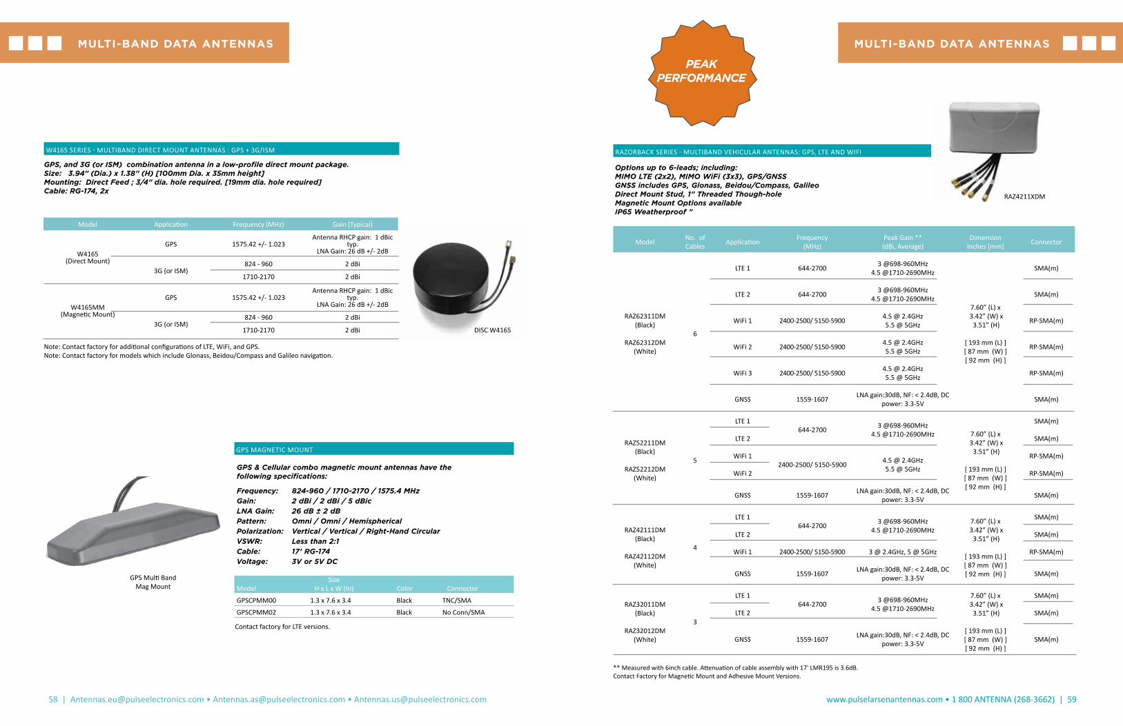
58 | [email protected] • [email protected] • [email protected]
www.pulselarsenantennas.com • 1 800 ANTENNA (268-3662) | 59
Options up to 6-leads; including:MIMO LTE (2x2), MIMO WiFi (3x3), GPS/GNSSGNSS includes GPS, Glonass, Beidou/Compass, GalileoDirect Mount Stud, 1" Threaded Though-holeMagnetic Mount Options availableIP65 Weatherproof "
Model No. of Cables Application Frequency
(MHz)Peak Gain ** (dBi, Average)
Dimension Inches [mm] Connector
RAZ62311DM (Black)
RAZ62312DM
(White)
6
LTE 1 644-2700 3 @698-960MHz 4.5 @1710-2690MHz
7.60” (L) x 3.42” (W) x
3.51” (H)
[ 193 mm (L) ] [ 87 mm (W) ] [ 92 mm (H) ]
SMA(m)
LTE 2 644-2700 3 @698-960MHz 4.5 @1710-2690MHz SMA(m)
WiFi 1 2400-2500/ 5150-5900 4.5 @ 2.4GHz 5.5 @ 5GHz RP-SMA(m)
WiFi 2 2400-2500/ 5150-5900 4.5 @ 2.4GHz 5.5 @ 5GHz RP-SMA(m)
WiFi 3 2400-2500/ 5150-5900 4.5 @ 2.4GHz 5.5 @ 5GHz RP-SMA(m)
GNSS 1559-1607 LNA gain:30dB, NF: < 2.4dB, DC power: 3.3-5V SMA(m)
RAZ52211DM (Black)
RAZ52212DM
(White)
5
LTE 1644-2700 3 @698-960MHz
4.5 @1710-2690MHz 7.60” (L) x 3.42” (W) x
3.51” (H)
[ 193 mm (L) ] [ 87 mm (W) ] [ 92 mm (H) ]
SMA(m)
LTE 2 SMA(m)
WiFi 12400-2500/ 5150-5900 4.5 @ 2.4GHz
5.5 @ 5GHz
RP-SMA(m)
WiFi 2 RP-SMA(m)
GNSS 1559-1607 LNA gain:30dB, NF: < 2.4dB, DC power: 3.3-5V SMA(m)
RAZ42111DM (Black)
RAZ42112DM
(White)
4
LTE 1644-2700 3 @698-960MHz
4.5 @1710-2690MHz7.60” (L) x
3.42” (W) x 3.51” (H)
[ 193 mm (L) ] [ 87 mm (W) ] [ 92 mm (H) ]
SMA(m)
LTE 2 SMA(m)
WiFi 1 2400-2500/ 5150-5900 3 @ 2.4GHz, 5 @ 5GHz RP-SMA(m)
GNSS 1559-1607 LNA gain:30dB, NF: < 2.4dB, DC power: 3.3-5V SMA(m)
RAZ32011DM (Black)
RAZ32012DM
(White)
3
LTE 1644-2700 3 @698-960MHz
4.5 @1710-2690MHz
7.60” (L) x 3.42” (W) x
3.51” (H)
[ 193 mm (L) ] [ 87 mm (W) ] [ 92 mm (H) ]
SMA(m)
LTE 2 SMA(m)
GNSS 1559-1607 LNA gain:30dB, NF: < 2.4dB, DC power: 3.3-5V SMA(m)
MULTI-BAND DATA ANTENNASMULTI-BAND DATA ANTENNAS
GPS Multi Band Mag Mount
GPS MAGNETIC MOUNT
GPS & Cellular combo magnetic mount antennas have the following specifications:
Frequency: 824-960 / 1710-2170 / 1575.4 MHz Gain: 2 dBi / 2 dBi / 5 dBicLNA Gain: 26 dB ± 2 dB Pattern: Omni / Omni / Hemispherical Polarization: Vertical / Vertical / Right-Hand Circular VSWR: Less than 2:1 Cable: 17’ RG-174 Voltage: 3V or 5V DC
Size Model H x L x W (In) Color Connector
GPSCPMM00 1.3 x 7.6 x 3.4 Black TNC/SMA
GPSCPMM02 1.3 x 7.6 x 3.4 Black No Conn/SMA
Contact factory for LTE versions.
RAZORBACK SERIES - MULTIBAND VEHICULAR ANTENNAS: GPS, LTE AND WIFI
PEAKPERFORMANCE
** Measured with 6inch cable. Attenuation of cable assembly with 17' LMR195 is 3.6dB.Contact Factory for Magnetic Mount and Adhesive Mount Versions.
RAZ4211XDM
Model Application Frequency (MHz) Gain (Typical)
W4165 (Direct Mount)
GPS 1575.42 +/- 1.023 Antenna RHCP gain: 1 dBic
typ. LNA Gain: 26 dB +/- 2dB
3G (or ISM)824 - 960 2 dBi
1710-2170 2 dBi
W4165MM (Magnetic Mount)
GPS 1575.42 +/- 1.023 Antenna RHCP gain: 1 dBic
typ. LNA Gain: 26 dB +/- 2dB
3G (or ISM)824 - 960 2 dBi
1710-2170 2 dBi
W4165 SERIES - MULTIBAND DIRECT MOUNT ANTENNAS : GPS + 3G/ISM
Note: Contact factory for additional configurations of LTE, WiFi, and GPS. Note: Contact factory for models which include Glonass, Beidou/Compass and Galileo navigation.
GPS, and 3G (or ISM) combination antenna in a low-profile direct mount package.Size: 3.94" (Dia.) x 1.38" (H) [100mm Dia. x 35mm height] Mounting: Direct Feed ; 3/4" dia. hole required. [19mm dia. hole required] Cable: RG-174, 2x
DISC W4165

60 | [email protected] • [email protected] • [email protected]
www.pulselarsenantennas.com • 1 800 ANTENNA (268-3662) | 61
ARMADILLO SERIES - MULTIBAND VEHICULAR DIRECT MOUNT ANTENNAS : GPS + LTE + WIFI New Low Profile Package Options up to 6-leads; including: MIMO LTE (2x2), MIMO WiFi (3x3), GPS/GNSS GNSS includes GPS, Glonass, Beidou/Compass, Galileo Direct Mount Stud, 1" Threaded Though-hole Magnetic Mount Options available IP65 Weatherproof
GPSMULTI-BAND DATA ANTENNASMULTI-BAND DATA ANTENNAS
LOW PROFILE
-Frequency detail of GNSS: 1561.098MHz±2.046/ 1575.42MHz±1.023/ 1602.5625MHz±4 ** Measured with 6inch cable. Attenuation of cable assembly with 17' coax is 3.6dB.
Model No. of Cables Application Frequency
(MHz)Peak Gain ** (dBi, Average)
Dimension (mm):
Mounting Method Connector
ARM62311DM (Black)
ARM62312DM (White)
6
LTE 1698-2700
1.5 @698-960MHz
4.5 @1710-2690MHz
7.9” (L) 3.5” (W) 1.77” (H)
[ 202 mm (L) ]
[ 88.5 mm (W) ] [ 45 mm (H) ]
Direct mount, ¾” (19mm) threaded
through-hole
SMA(m)
LTE 2 SMA(m)
WiFi 1 2400-2500/ 5150-5900 3 @ 2.4GHz, 5 @ 5GHz RP-SMA(m)
WiFi 2 2400-2500/ 5150-5900 3 @ 2.4GHz, 5 @ 5GHz RP-SMA(m)
WiFi 3 2400-2500/ 5150-5900 3 @ 2.4GHz, 5 @ 5GHz RP-SMA(m)
GNSS 1559-1607 LNA gain:30dB, NF: < 2.4dB, DC power: 3.3-5V
SMA(m)
ARM52211DM (Black)
ARM52212DM (White)
5
LTE 1698-2700
1.5 @698-960MHz
4.5 @1710-2690MHz 7.9” (L)
3.5” (W) 1.77” (H)
[ 202 mm (L) ]
[ 88.5 mm (W) ] [ 45 mm (H) ]
Direct mount, ¾” (19mm) threaded
through-hole
SMA(m)
LTE 2 SMA(m)
WiFi 1 2400-2500/ 5150-5900 3 @ 2.4GHz, 5 @ 5GHz RP-SMA(m)
WiFi 2 2400-2500/ 5150-5900 3 @ 2.4GHz, 5 @ 5GHz RP-SMA(m)
GNSS 1559-1607 LNA gain:30dB, NF: < 2.4dB, DC power: 3.3-5V
SMA(m)
ARM42111DM (Black)
ARM42112DM (White)
4
LTE 1698-2700
1.5 @698-960MHz
4.5 @1710-2690MHz
7.9” (L) 3.5” (W) 1.77” (H)
[ 202 mm (L) ]
[ 88.5 mm (W) ] [ 45 mm (H) ]
Direct mount, ¾” (19mm) threaded
through-hole
SMA(m)
LTE 2 SMA(m)
WiFi 1 2400-2500/ 5150-5900 3 @ 2.4GHz, 5 @ 5GHz RP-SMA(m)
GNSS 1559-1607 LNA gain:30dB, NF: < 2.4dB, DC power: 3.3-5V
SMA(m)
ARM32011DM (Black)
ARM32012DM (White)
3
LTE 1698-2700
1.5 @698-960MHz
4.5 @1710-2690MHz
7.9” (L) 3.5” (W) 1.77” (H)
[ 202 mm (L) ]
[ 88.5 mm (W) ] [ 45 mm (H) ]
Direct mount, ¾” (19mm) threaded
through-hole
SMA(m)
LTE 2 SMA(m)
GNSS 1559-1607 LNA gain:30dB, NF: < 2.4dB, DC power: 3.3-5V
SMA(m)
ARM42111MM (Black, Mag Mt)
ARM42112MM
(White, Mag Mt)
4
LTE 1698-2700
1.5 @698-960MHz
4.5 @1710-2690MHz
7.9” (L) 3.5” (W) 1.77” (H)
[ 202 mm (L) ]
[ 88.5 mm (W) ] [ 45 mm (H) ]
Magnetic mount
SMA(m)
LTE 2 SMA(m)
WiFi 1 2400-2500/ 5150-5900 3 @ 2.4GHz, 5 @ 5GHz RP-SMA(m)
GNSS 1559-1607 LNA gain:30dB, NF: < 2.4dB, DC power: 3.3-5V
SMA(m)
ARM42111AM (Black, Adhesive
Mt)
ARM42112AM (White,
Adhesive Mt)
4
LTE 1698-2700
1 @698-960MHz 3.5
@1710-2690MHz 7.9” (L) 3.5” (W) 1.77” (H)
[ 202 mm (L) ]
[ 88.5 mm (W) ] [ 45 mm (H) ]
Adhesive Mount
SMA(m)
LTE 2 SMA(m)
WiFi 1 2400-2500/ 5150-5900 3 @ 2.4GHz, 5 @ 5GHz RP-SMA(m)
GNSS 1559-1607 LNA gain:30dB, NF: < 2.4dB, DC power: 3.3-5V
SMA(m)
Model Application Frequency(MHz) Gain (dBi) VSWR Mount Size (in.) Cable Conn.
LTE1, LTE2
698-9601695-21702300-27002900-3600
4 (LB)5 (UB) 1.5:1 7/8” Hole
(M22 Nut) 6.5x6x3 17’ RG-58 SMASMA
GPSMB501(5 CABLES) WIFI1, WIFI2 2400-2500
4900-5900 4.5 / 5 1.5:1 7/8” Hole(M22 Nut) 6.5x6x3 17’ RG-58 RP-SMA
RP-SMA
GPS, GLONASS 1564-1610 1.5 (dBic) 1.5:1 7/8” Hole(M22 Nut) 6.5x6x3 17’ RG-174 SMA
GPSMB301 LTE, LTE2
698-9601695-21702300-27002900-3600
6 (LB)5.5 (UB) 1.7:1 7/8” Hole
(M22 Nut) 6.5x6x3 17’ RG-5817’ RG-58
SMASMA
GPS, GLONASS 1575-1609 1.5 (dBic) 1.7:1 7/8” Hole(M22 Nut) 6.5x6x3 17’ RG-174 SMA
PANTHER SERIES - DIRECT MOUNTS
NOTE: GPSMBMM is a magnetic base for GPSMB501 and GPSMB301. White and black colors available.
GPSMB501 GPSMB301GPSMB Panther (White)
ARMADILLO

62 | [email protected] • [email protected] • [email protected]
NMO4EEF NMO5E
PUBLIC SAFETY AND WIFI BROADBAND ANTENNAS
Frequency Gain Max Height CableModel Type (MHz) (dBi) (In) VSWR Assembly
EF2405NMO Elevated Feed 2400-2500 5 16 <1.5:1 Order Separately
EF4905NMO Elevated Feed 4900-5000 5 12 <1.5:1 Order Separately
NMO4E4900B Elevated Feed 4900-5350 4 4.5 2:1 Order Separately
NMO4E5350B Elevated Feed 5350-5925 4 4.5 2:1 Order Separately
NMO5E2400B Collinear 2400-2500 2.95 8.5 1.5:1 Order Separately
NOTE: All NMO mount antennas listed in this catalog section require the NMOHF-style (high frequency 27 MHz - 6 GHz) mount.
Through its rich history in the Larsen and LK brands, Pulse has over 50 years in the antenna business.
OUTDOOR VEHICULAR: LTE, 4G, BROADBANDALL MADE IN THE USA
www.pulselarsenantennas.com • 1 800 ANTENNA (268-3662) | 63
WIFI, BROADBAND STEALTH BLADES
Stealth Blade antennas have a gain of 2.14 dBi, a maximum power of 3 Watts and linear polarization
Frequency Dimensions Model (MHz) Type L x W (In) Color Coax Connector
*SB24003 2400-2500 Dipole 3 x .75 Black 3’ RG-174 No Conn
*SB24006 2400-2500 Dipole 3 x .75 Black 6’ RG-174 No Conn
*SB2400SMA3 2400-2500 Dipole 3 x .75 Black 3’ RG-174 SMA
*SB2400SMA6 2400-2500 Dipole 3 x .75 Black 6’ RG-174 SMA
*SB2400SMB3 2400-2500 Dipole 3 x .75 Black 3’ RG-174 SMB
*SB2400SMB6 2400-2500 Dipole 3 x .75 Black 6’ RG-174 SMB
*SB2400MMCX3 2400-2500 Dipole 3 x .75 Black 3’ RG-174 MMCX
*SB2400MMCX6 2400-2500 Dipole 3 x .75 Black 6’ RG-174 MMCX
SB698SMA3 698-960 / 1710-2170 / 2300-2700 Dipole 4.2 x 1 Black 3’ RG-316 SMA
SB698SMA12 698-960/1710-2170/2300-2700 Dipole 4.2 x 1 Black 12' RG-316 SMA
NOTE: All NMO mount antennas listed in this catalog section require the NMOHF-style (high frequency 27 MHz - 6 GHz) mount.
LPTSLPT DMSLPT
NMO
ICEFIN698-960NMO ICEFIN806DMN
SB2400xx
PUBLIC SAFETY 700/800; 2G/3G/4G LTE; WIFI; DSRC – LOW PROFILE
Model Black Model White ICEFIN Model Frequency (MHz) Gain (dBi) Mount Size Hx
DIA (in)Power Rating (Watts)
Black / White / ICEFIN
*LPT825/19NMOHF N/A NACellular: 806-960PCS: 1710-2170
ISM: 2400
334
NMOHF 3 x 1.75 10 / 10 / NA
*LPT2400NMOHF LPT2400NMOHFW NA 2400-2500 5 NMOHF 3 x 1.75 10 / 10 / NA
**SLPT698/2170NMOHF SLPT698/2170NMOHFW ICEFINLNMOHFLTE: 698-960
PCS: 1710-2170ISM: 2400-2700
4.55.64
NMOHF 3 x 1.75 40 / 40 / 30
**SLPT2400NMOHF SLPT2400NMOHFW ICEFIN24NMOHF 2400-2500 4.3 NMOHF2.6 x 1.5
35 / 35 / 30
**SLPT4900NMOHF SLPT4900NMOHFW ICEFIN49NMOHF 4900-5900 5.5 NMOHF2.6 x 1.5
35 / 35 / 30
**SLPT2400/5900NMOHF SLPT245NMOHFW ICEFINWNMOHF 2400-25004900-5900
4.35.5 NMOHF
2.6 x 1.5
35 / 35 / 30
**SLPT698/2170DMN SLPT698/2170DMNW ICEFINLDMNLTE: 698-960
PCS: 1710-2170ISM: 2400-2700
4.55.64
Direct (N Female) 3 x 1.75 40 / 40 / 35
**SLPT2400DMN SLPT2400DMNW ICEFIN24DMN 2400-2500 4.3 Direct (N Female)
2.6 x 1.5
35 / 35 / 30
**SLPT4900DMN SLPT4900DMNW ICEFIN49DMN 4900-5900 5.5 Direct (N Female)
2.6 x 1.5
35 / 35 / 30
GPSOUTDOOR VEHICULAR: LTE, 4G, BROADBAND
* MADE IN THE USA ** IP67 RATED

64 | [email protected] • [email protected] • [email protected]
www.pulselarsenantennas.com • 1 800 ANTENNA (268-3662) | 65
LTE, 4G, BROADBAND RADOME OMNIS
Radome Enclosure: Pultruded Fiberglass (UV Protected)VSWR: 2.0:1 Power Rating: 20 WattsIngress Protection: IP67 Polarization: VerticalSuggested mounting brackets for N Female connectors are FB2BRACKET or FB3BRACKET. See Page 53 for FB brackets.
Frequency Gain Length Model (MHz) (dBi) (In) Connector
**W5067 (1) 698-960 0.7 9.1 N Female
1710-2170 1.0 2400-2700 2.0**RO17102NM(2) 1710-2170 2 4.5 N Male**RO8605NFC(3) 860 - 930 5.0 32 N Female*RO2404NM 2400-2500 4 11.5 N Male*RO2406NF 2400-2500 6 11.5 N Female*RO2406NM 2400-2500 6 11.5 N Male**RO2408NF 2400-2500 8 20 N Female**RO2408NM 2400-2500 8 20 N Male**RO2408NFD (downtilt) 2400-2500 8 20 N Female**RO2408NMD (downtilt) 2400-2500 8 20 N Male**RO2408NFU (uptilt) 2400-2500 8 20 N Female**RO2408NMU (uptilt) 2400-2500 8 20 N Male*RO4502NF** 450-512 2 18.4 N Female*RO4910NF** 4940-4990 10 18 N Female*RO4910NM** 4940-4990 10 18 N Male*RO5206NF** 5150-5350 6 6.75 N Female*RO5410NF** 5470-5725 10 16.5 N Female*RO5210NF** 5150-5350 10 16.5 N Female*RO5210NM** 5150-5350 10 16.5 N Male*RO5410NM** 5470-5725 10 16.5 N Male*RO5805NF** 5150-5825 5 6.75 N Female*RO5805NM** 5150-5825 5 6.75 N Male*RO5806NF** 5725-5875 6 6.75 N Female*RO5810NF** 5725-5875 10 16.5 N Female*RO5810NM** 5725-5875 10 16.5 N Male**RO8063/21704NM 806-960 3 16.5 N Male**RO8063/21704NF 1710-2170 4 N Female**RO8061/21702NM 824-960v 1 8.6 N Male 1710-2170 2**W5030 2400-2500 4 6.8 N Male 5150-5875 6**RO3ISMNM 430-440 2 21.3 N Male 860-930 2.5**RO25002NF(2) 2300-2700 2.0 5.1 N Female(1) 3 Watt Power (2) PIM Rated to -155 dBc (3) Bracket ROKIT Available. Contact Factory.
Radome Omnis
YAGIS
Construction: Fully Welded Elements Wind Load: 100 mphVSWR: 2.0:1 Feed Connection: N FemalePower Rating: 300 Watts Mounting Hardware: Included # of Frequency Gain LengthModel Elements (MHz) (dBi) (In)*YA3406WN 5 406-430 11 42.25*YA3450WN 5 450-470 11 36.25*YA5740W 7 740-806 11 32.75*YA6740W 4 740-806 8 19.25*YA5800W 7 806-866 11 31.25*YA6800W 4 806-866 8 17.5*YA5825W 7 824-896 11 31.25*YA6825 4 824-896 8 17.5*YA5900W 7 890-960 11 30
*YA6900W 4 890-960 8 17.5
YA6 Series
YA5 Series
YA3 Series
OUTDOOR ANTENNAS*MADE IN THE USA**IP67 RATED
OMNI BASE STATION ANTENNAS
Omni Base Station part numbers ending in “WA” do not include mounting hardware. All others includes the appropriate FB2BRACKET or FB3BRACKET for mounting. See Page 78 for FB brackets.
Max Power Frequency Gain Height Rating Whip FeedModel Type (MHz) (dBi) (In) (Watts) Color Connection
BSA45C Base Loaded 1/4 λ 45-50 2 51.75 200 Stainless N Female
BSA118B 5/8 λ 118-121 5.2 64 200 Black UHF Female
BSA132B 5/8 λ 131-135 5.2 54.5 200 Black UHF Female
BSA150B 5/8 λ 144-174 5.2 51.75 200 Black UHF Female
BSA150C 5/8 λ 144-174 2.5 51.75 200 Black UHF Female
BSA220C 5/8 λ 200-225 5.2 33.75 200 Stainless UHF Female
BSA406C 5/8 over 1/2 λ 406-420 5.6 32 200 Stainless UHF Female
BSA440C 5/8 over 1/2 λ 440-460 5.6 32 200 Stainless UHF Female
BSA450C 5/8 over 1/2 λ 450-470 5.6 32 200 Stainless UHF Female
BSAKIT Base Station Ground Plane Kit 200 UHF Female
FB1136 5/8 over 1/2 λ 136-230 5.6 96 200 Stainless UHF Female
FB2406 5/8 over 1/4 λ 406-420 5.4 32.5 200 Black N Female
FB2450 5/8 over 1/4 λ 450-470 5.4 32.5 200 Black N Female
FB2406W/A 5/8 over 1/4 λ 406-420 5.4 32.25 200 Black N Female
FB2420W/A 5/8 over 1/4 λ 420-440 5.4 32.25 200 Black N Female
FB2450W/A 5/8 over 1/4 λ 450-470 5.4 32.25 200 Black N Female
FB3800 5/8 over 1/4 λ 806-866 5.4 16 150 Black N Female
FB3825 5/8 over 1/4 λ 824-896 5.4 16 150 Black N Female
FB3740WA 5/8 over 1/4 λ 740-806 5.4 16 150 Black N Female
FB3800WA 5/8 over 1/4 λ 806-866 5.4 16 150 Black N Female
FB3825WA 5/8 over 1/4 λ 824-896 5.4 16 150 Black N Female
FB35T800 5/8 over 5/8 over 1/4 λ 806-866 5.4 32 150 Black N Female
FB35T825 5/8 over 5/8 over 1/4 λ 824-896 5.4 32 150 Black N Female
FB35T800WA 5/8 over 5/8 over 1/4 λ 806-866 7.2 32 150 Black N Female
FB35T825WA 5/8 over 5/8 over 1/4 λ 824-896 7.2 32 150 Black N Female
FB900 5/8 over 1/4 λ 890-960 5.4 16 150 Black N Female
FB3900WA 5/8 over 1/4 λ 890-960 5.4 16 150 Black N Female
FB35T900 5/8 over 5/8 over 1/4 λ 890-960 7.2 23 150 Black N Female
FB35T900WA 5/8 over 5/8 over 1/4 λ 890-960 7.2 23 150 Black N Female
FB45T2400 5/8 over 5/8 over 1/4 λ 2400-2485 7.2 16.5 100 Black N Female
FB45T2400WA 5/8 over 5/8 over 1/4 λ 2400-2485 7.2 9 100 Black N Female
BSA45CBSA B
BSAKIT FB1136
FB2
FB3
FB3FB35T
FB45T
BASE STATION ANTENNASALL MADE IN THE USA

66 | [email protected] • [email protected] • [email protected]
www.pulselarsenantennas.com • 1 800 ANTENNA (268-3662) | 67
DAS
From Your Low-Pim Solutions Expert
Distributed Antenna Systems: As consumers switch to a lifestyle of constant internet connection, the demand on wireless networks increases dramatically. The carrier networks are switching from one of coverage to capacity. Previously coverage came via cellular base stations with tower-mounted antennas with vast reach to many consumers. The future networks need to fulfill capacity demands by bringing those networks closer to the consumer, with greater data throughput reaching customers in smaller coverage areas. To meet these very high data rates it’s critical to have high quality innovative components such as Pulse Electronics PIMinator™ line of in-building low-PIM antennas, Pulse clarity™ transparent antennas and accessory components.
Maker Of Clarity™ Transparent Antennas!
Clarity™ Transparent Antenna Clarity™ White Antenna
ULTRA-THIN CLARITY™ ANTENNAS
Clarity™ Series
Pulse Part Number Freq, MHz
PIM Rating,
dBcConnector
Ultra-Thin Clear DASUTCC500NF 608-960/1695-2200/2300-2700MHz, Antenna only -155 N Female
w/500mm pigtail
Ultra-Thin Clear DASUTCCR500NF 608-960/1695-2200/2300-2700MHz, with Reflector -155 N Female
w/500mm pigtail
Ultra-Thin Clear DASUTCC500MD 608-960/1695-2200/2300-2700MHz, Antenna only -155 4.1-9.5 Mini-DIN Female
w/500mm pigtail
Ultra-Thin Clear DASUTCCR500MD 608-960/1695-2200/2300-2700MHz, with Reflector -155 4.1-9.5 Mini-DIN Female
w/500mm pigtail
Ultra-Thin Clear DASUTCC5004310 608-960/1695-2200/2300-2700MHz, Antenna only -155 4.3-10 DIN Female
w/500mm pigtail
Ultra-Thin Clear DASUTCCR5004310 608-960/1695-2200/2300-2700MHz, with Reflector -155 4.3-10 DIN Female
w/500mm pigtail
Clarity DASUTCCACC1 Reflector N/A N/A
Ultra-Thin White DASUTWC500NF 608-960/1695-2200/2300-2700MHzAntenna Only -155 N Female
w/ 500mm pigtail
Ultra-Thin White DASUTWCR500NF 608-960/1695-2200/2300-2700MHz, with Reflector -155 N Female
w/ 500mm pigtail
Ultra-Thin White DASUTWC500MD 608-960/1695-2200/2300-2700MHzAntenna Only -155 4.1-9.5 Mini-DIN Female
w/ 500mm pigtail
Ultra-Thin White DASUTWCR500MD 608-960/1695-2200/2300-2700MHz, with Reflector -155 4.1-9.5 Mini-DIN Female
w/ 500mm pigtail
Ultra-Thin White DASUTWC5004310 608-960/1695-2200/2300-2700MHzAntenna Only -155 4.3-10 DIN Female
w/500mm pigtail
Ultra-Thin White DASUTWCR5004310 608-960/1695-2200/2300-2700MHz, with Reflector -155 4.3-10 DIN Female
w/500mm pigtail
DAS
DASLTENFDASLTE500NF DASSPLIT3WNF
AntennasPulse Part Number
Freq, MHzPIM
Rating, dBcConnector
MIMO Ceiling Mount DASLTE500NFMIMO 698-960/1710-2170/2300-2700/4900-5900 -155N Female w/500mm pigtail (2x)
MIMO Ceiling Mount DAS500MDMIMO 698-960/1710-2170/2300-2700/4900-5900` -155Mini-DIN (4.1/9.5)Female w/500mm
pigtail
SISO Ceiling Mount
DASLTE500NF 698-960/1710-2170/2300-2700/4900-5900 -155N Female
w/500mm pigtail
SISO Ceiling Mount
DASLTENF 698-960/1710-2170/2300-2700/4900-5900 -155N Female
w/500mm pigtail
SISO Ceiling Mount
DASLTEMINIDIN 698-960/1710-2170/2300-2700/4900-5900 -155Mini-DIN
(4.1 / 9.5) Femalew/ 500mm pigtail
SISO Ceiling Mount
DASLTEDIN 698-960/1710-2170/2300-2700/4900-5900 -155 DIN (7 / 16)
RF Splitters Pulse Part Number Freq, MHzPIM
Rating, dBcConnector
Power Splitter, 2-Way, 300W DASSPLIT2WDIN 698-2700 -155 DIN
Power Splitter, 2-Way, 300W DASSPLIT2WNF 698-2700 -155 N Female
Power Splitter, 3-Way 300W DASSPLIT3WNF 698-2700 -155 N Female
Power Splitter, 4-Way, 300W DASSPLIT4WNF 698-2700 -155 N Female

68 | [email protected] • [email protected] • [email protected]
www.pulselarsenantennas.com • 1 800 ANTENNA (268-3662) | 69
PUBLIC SAFETY DAS PRODUCTS
Application Frequency, MHz SeriesPart
NumberPIM
RatingConnector Color
Size (inches / mm)
UHF + 700/800 380-570; 698-960 Clarity™ -Pearl PSUTWCNF N/A N-Female White12.3” (311mm)
Diameter.0.37” (9.5mm) Below ceiling
VHF 132-174 V-Thinity™ PSIBVHF N/A N-Female White15.0x15.0 inch (380x380mm)
Below Ceiling: 0.060 inch (1.5mm)
VHF + UHF + 700/800132-174; 380-570; 700-960
V-Thinity™ PSIBVU78 N/A N-Female White
15.4 x 13.6 inch (391 x 346mm) Below
Ceiling: 0.06 inch (1.5mm)”)
Installed Condition:PSIBVHF and PSIBVU78
PSIBVHF and PSIBVU78 PSUTWCNF
PSDASxx Series Top View PSDASxx Series Bottom View
PUBLIC SAFETY + CARRIER COMBO DAS PRODUCT
Application Frequency, MHz SeriesPart
NumberPIM
RatingConnector Color
Size (inches / mm)
UHF (Tetra) + 3G/4G LTE (or WiFi)
380-520; 698-960;
1710-2700; 4900-60005Bar PSDAS4310F N/A 4.3-10 White
11.3 Dia x 5.4 Tall (288mm Dia.
X 136mm Tall)
UHF (Tetra) + 3G/4G LTE (or WiFi)
380-520; 698-960;
1710-2700; 4900-60005Bar PSDAS4310FP
-150dBc (@2x20 watts)
4.3-10 White11.3 Dia x 5.4 Tall
(288mm Dia. X 136mm Tall)
UHF (Tetra) + 3G/4G LTE (or WiFi)
380-520; 698-960;
1710-2700; 4900-60005Bar PSDASNF N/A N-Female White
11.3 Dia x 5.4 Tall (288mm Dia.
X 136mm Tall)
UHF (Tetra) + 3G/4G LTE (or WiFi)
380-520; 698-960; 1710-2700; 4900-6000
5Bar PSDASNFP-150dBc
(@2x20 watts)N-Female White
11.3 Dia x 5.4 Tall (288mm Dia. X 136mm Tall)
DAS
Above-Ceiling Antenna Holder
DAS PIM-Blocker Absorber
Above-Ceiling Antenna Holder (Shown with Antenna Installed)
Clarity Installation Adapter
Typical Assembly using the Clarity Installation Adapter
Slots
Tabs
Installation Adapter
Ceiling Structure
ItemsPart
NumberFunction Material Size Comments
Above-Ceiling Antenna Holder
DASACHOLDERSupport antennas above ceiling tile
rails.
Polycarbonate; 618x192x122 mm (24.4x7.6x4.4 inch)
The holder includes snap-in-place brackets for easy installation onto most standard ceiling tiles rails. Antennas are robustly held in place so the antennas cannot be disturbed when building tenant moves ceiling tiles and impacts the antenna. The plastic construction ensures PIM is not aggrevated unlike competitive ferrous metal holders.
Clarity Installation Adapter
DASCLINSERTBlind-hole
installation of Clarity Antennas.
94 mm dia (3.7 inch dia)
The Installation adapter allows one-sided (blind-hole) installation of Clarity antennas when the building construction does not provide access to the backside of the antenna for installation of the provided nut. Ideal for hardpan, drywall, plank and other architectural ceiling types.
PIM-Blocker Absorber
DASACABSORBERSystem PIM Reduction
(19.7 x 19.7 x 2.0 inch)
The PulseLarsen PIM Blocker absorber bag can reduce PIM by as much as 40dB when placed between antennas and the surrounding structure. The PulseLarsen PIM Blocker can also be used to improve isolation in BDA Repeater applications. See Datasheet for more details.
DAS ACCESSORIES

70 | [email protected] • [email protected] • [email protected]
www.pulselarsenantennas.com • 1 800 ANTENNA (268-3662) | 71
LOW COST MONOPOLE WITH GROUND PLANE SOLUTION
SLPT White Series Antenna IceFin™ Series Antenna Peak
Gain*PIM
Rating Connector Mechanical Properties
Application Frequency, MHz Color Part
Number Color Part Number
700 / 800 698-869 White SLPT698/869DMNW Transparent ICEFIN698/869DMN 3.3 dBi None N-Female
1.5” dia x 3.1” tall
(38mm dia. X 79 mm tall)
2G / 3G / 4G LTE 698-960 / 1710-2700 White SLPT698/2170DMNW Transparent ICEFINLDMN
3.5 dBi (lower band)
4.95 dBi (upper band)
None N-Female
1.5” dia x 3.1” tall
(38mm dia. X 79 mm tall)
* Gain when using ground plane
ICEFIN WhiteICEFIN Transparent
Application Part Number Mechanical Properties
Ground Plane (for use
with above antennas)ICEFIN-GP
15.75” Dia. X 0.040” thk
(400mm Dia. X 1mm thk)Material: Aluminum”
Frame(for use
with above antennas)ICEFIN-F 2.95” Dia. (74.9mm Dia).
Installed Configuration Frame and ScrewsInstalled Configuration Ground Plane
DAS
IN-BUILDING ANTENNA FREQUENCY (MHZ) HEIGHT (IN/MM) GAIN (DBI) CONNECTOR
Single Band Baton Style
RO17102NM 1710-2170 4.5 / 115 2N Female
w/ 500mm pigtail
Multi Band Baton Style
W5067698 - 960 / 1710 - 2170 /
2400 - 27009.1 / 230 1 / 2 N Female
RO8061/21702NF 806-960/1710-2170 8.5 / 216 1 / 2 N Female
RO8061/21702NM 806-960/1710-2170 8.5 / 216 1 / 2 N Male
RO8063/21704NF 806-960/1710-2170 15.3 / 389 3 / 4 N Female
RO8063/21704NM 806-960/1710-2170 15.3 / 389 3 / 4 N Male
W5030 2.4-2.5/5.15-5.875 GHz 6.8 / 173 4 / 6 N Male
Public Safety Antennas
Model Number (**) Available Frequencies Gain Connector
Donor Yagi YA34xxWN 406 thru 512Mhz 11 dBi N Female
Donor Yagi YA5xxW 740 thru 960 11 dBi N Female
Donor Yagi YA6xxW 740 thru 960 8 dBi N Female
Base Station FB24xx WA 406 thru 470 5.4 dBi N Female
Base Station FB3xxx 740 thru 960 5.4 dBi N Female
Base Station FB35T900x 902 thru 928 7.2 dBi N Female
**See specific datasheet for Part Number and coverage frequency.
DAS OTHER ACCESSORIES

72 | [email protected] • [email protected] • [email protected]
www.pulselarsenantennas.com • 1 800 ANTENNA (268-3662) | 73
NMO 3/4” HIGH FREQUENCY MOUNTS
Model Coax Connector
*NMOKHFCX CX (RG-58A/U) No Conn
*NMOKHFCXFME CX (RG-58A/U) FME CRIMP
*NMOKHFCXMPL CX (RG-58A/U) MPL
*NMOKHFCXPL CX (RG-58A/U) PL-259
*NMOKHFDS DS (RG-58A/U Dual Shield) No Conn
NMOKHFUD UD (RG-58U Dual Shield) No Conn
*NMOKHFUDFME UD (RG-58U Dual Shield) FME
*NMOKHFUDMPL UD (RG-58U Dual Shield) MPL
*NMOKHFUDSMA UD (RG-58U Dual Shield) SMA
*NMOKHFUDTNC UD (RG-58U Dual Shield) TNC
*NMOKHF200SMAI LMR200 SMA Installed
NMO 3/4” HIGH FREQUENCY MID-SIZE MOUNTS
Model Coax Connector
*NMOKHFMIDCX CX (RG-58A/U) No Conn
*NMOKHFMIDDS DS (RG-58A/U Dual Shield, Low Loss) No Conn
*NMOKHFMIDUD UD (RG-58U, Dual Shield) No Conn
NMO 3/4” HIGH FREQUENCY THICK MOUNTS
Model Coax Connector
*NMOKHFCXTHK CX (RG-58A/U) No Conn
*NMOKHFDSTHK DS (RG-58A/U Dual Shield) No Conn
NMOHF MountHigh Frequency Configuration
NMOHF MountLow Frequency Configuration
NMO 3/4” STANDARD MOUNTS
NMO 3/4” standard mounts require a 3/4” hole for mounting and include 17’ of coax.
Model Coax Connector
NMOKNOCONN CX (RG-58A/U) No Conn
*NMOK CX (RG-58A/U) PL-259
*NMOKFME CX (RG-58A/U) FME
*NMOKMPL CX (RG-58A/U) MPL Crimp
*NMOKDS DS (RG-58A/U Dual Shield) No Conn
*NMOKDSFME DS (RG-58A/U Dual Shield) FME
NMOKUD UD (RG-58U Dual Shield) No Conn
*NMOKUDFME UD (RG-58U Dual Shield) FME
*NMOKUDPL UD (RG-58U Dual Shield) PL-259T
*NMOKUDTNC UD (RG-58U Dual Shield) TNC
If your antenna has a “tab” or “pin” connector, use the NMOHF mount in the low frequency configuration - leave the center pin and insulator in place as it arrives from the factory.
If your antenna has a “high frequency” (HF) connector, use the NMOHF mount in the high frequency configuration - remove the center pin and insulator.
“Pin”connector
“Tab”connector
“HF”connector
NMOHF Thick MountLow FrequencyConfiguration
NMOHF Thick MountHigh FrequencyConfiguration
All Larsen NMOHF (high frequency 27 MHz to 6 GHz) mounts convert from low frequency applications to high frequency applications and back by pulling or replacing the center pin and insulator.
NMOHF mounts require a 3/4” hole for mounting and include 17’ of coax. NMOHF mounts accommodate roof surfaces from 0.1” to .03”. NMOHFTHK (thick) mounts accommodates roof surfaces up to 1/2” thick.
CABLE ASSEMBLIES/MOUNTS *MADE IN THE USA
All Larsen NMOHF (high frequency 27 MHz to 6 GHz) mounts convert from low frequency applications to high frequency applications and back by pulling or replacing the center pin and insulator.
NMO HIGH FREQUENCY MAGNETIC MOUNTS
NMOHF round magnetic mounts have the following specifications:
Size: 3.5” DiameterCable Length: 12’Pull Strength: 80 lbs
Model Coax Connector
*NMOMMRNOCONN CX (RG-58A/U) No Conn
*NM0MMR CX (RG-58A/U) 58FCP
*NMOMMRFME CX (RG-58A/U) FME Crimp
*NMOMMRPL CX (RG-58A/U) PL-259
*NMOMMRMPL CX (RG-58A/U) MPL Crimp
*NMOMMRTNC CX (RG-58A/U) TNC Crimp
*NMOMMRBNC CX (RG-58A/U) BNC Crimp
*NMOMMRN CX (RG-58A/U) N Crimp
*NMOMMRDS DS (RG-58A/U Dual Shield) No Conn
*NMOMMRDSFME DS (RG-58A/U Dual Shield) FME
*NMOMMRDSMPL DS (RG-58A/U Dual Shield) MPL Crimp
*NMOMMRDSN DS (RG-58A/U Dual Shield) N Crimp
*NMOMMRDSSMA DS (RG-58A/U Dual Shield) SMA
*NMOMMRDSSMAR/P DS (RG-58A/U Dual Shield) SMARP
*NMOMMRDSPL DS (RG-58A/U Dual Shield) PL-259T
*NMOMMRDSTNC DS (RG-58A/U Dual Shield) TNC
*NMOMMT200NOCONN LMR200 No Conn
*NMOMMR200SMA LMR200 SMA
*NMOMMR200N LMR200 N
NMO 3/8” THICK MOUNTS
NMO3/8” mounts have the following specifications:
Mounting: 3/4” holeMounting Surface: 0.15” to 0.22” thicknessCable Length: 17’
Model Coax Connector
*NMOKCX38THK CX (RG-58A/U) No Conn
*NMOKUD38THK DS (RG-58A/U Dual Shield) No Conn
NMO HIGH FREQUENCY MOUNTS
Model Thickness Cable
NMOHF 0.761-2.54 mm Standard Not included
NMOHFMID 0.761 - 5.90 mm Mid-Thickness Not included
NMOHFTHK 1.6 - 12.7 mm Greatest Thickness Not included
CABLE ASSEMBLIES/MOUNTS*MADE IN THE USA
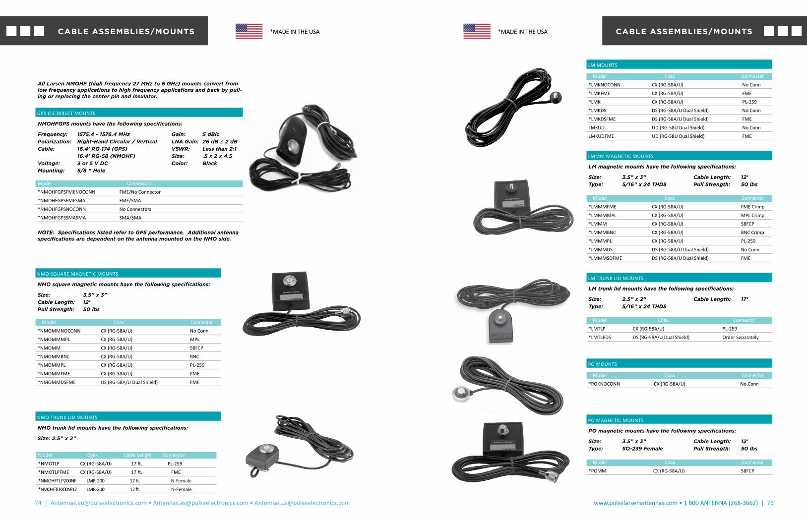
74 | [email protected] • [email protected] • [email protected]
www.pulselarsenantennas.com • 1 800 ANTENNA (268-3662) | 75
NMO SQUARE MAGNETIC MOUNTS
NMO square magnetic mounts have the following specifications:
Size: 3.5” x 3”Cable Length: 12’Pull Strength: 50 lbs
Model Coax Connector
*NMOMMNOCONN CX (RG-58A/U) No Conn
*NMOMMMPL CX (RG-58A/U) MPL
*NMOMM CX (RG-58A/U) 58FCP
*NMOMMBNC CX (RG-58A/U) BNC
*NMOMMPL CX (RG-58A/U) PL-259
*NMOMMFME CX (RG-58A/U) FME
*NMOMMDSFME DS (RG-58A/U Dual Shield) FME
NMO TRUNK LID MOUNTS
NMO trunk lid mounts have the following specifications:
Size: 2.5” x 2”
All Larsen NMOHF (high frequency 27 MHz to 6 GHz) mounts convert from low frequency applications to high frequency applications and back by pull-ing or replacing the center pin and insulator.
GPS LTE DIRECT MOUNTS
NMOHFGPS mounts have the following specifications:
Frequency: 1575.4 - 1576.4 MHz Gain: 5 dBicPolarization: Right-Hand Circular / Vertical LNA Gain: 26 dB ± 2 dBCable: 16.4’ RG-174 (GPS) VSWR: Less than 2:1 16.4’ RG-58 (NMOHF) Size: .5 x 2 x 4.5Voltage: 3 or 5 V DC Color: BlackMounting: 5/8 “ Hole
Model Connectors
*NMOHFGPSFMENOCONN FME/No Connector
*NMOHFGPSFMESMA FME/SMA
*NMOHFGPSNOCONN No Connectors
*NMOHFGPSSMASMA SMA/SMA
NOTE: Specifications listed refer to GPS performance. Additional antenna specifications are dependent on the antenna mounted on the NMO side.
Model Coax Cable Length Connector
*NMOTLP CX (RG-58A/U) 17 ft. PL-259
*NMOTLPFME CX (RG-58A/U) 17 ft. FME
*NMOHFTLP200NF LMR-200 17 ft. N-Female
*NMOHFTLP200NF12 LMR-200 12 ft. N-Female
CABLE ASSEMBLIES/MOUNTS *MADE IN THE USA
LM MOUNTS
Model Coax Connector
*LMKNOCONN CX (RG-58A/U) No Conn
*LMKFME CX (RG-58A/U) FME
*LMK CX (RG-58A/U) PL-259
*LMKDS DS (RG-58A/U Dual Shield) No Conn
*LMKDSFME DS (RG-58A/U Dual Shield) FME
LMKUD UD (RG-58U Dual Shield) No Conn
LMKUDFME UD (RG-58U Dual Shield) FME
LMMM MAGNETIC MOUNTS
LM magnetic mounts have the following specifications:
Size: 3.5” x 3” Cable Length: 12’Type: 5/16” x 24 THDS Pull Strength: 50 lbs
Model Coax Connector
*LMMMFME CX (RG-58A/U) FME Crimp
*LMMMMPL CX (RG-58A/U) MPL Crimp
*LMMM CX (RG-58A/U) 58FCP
*LMMMBNC CX (RG-58A/U) BNC Crimp
*LMMMPL CX (RG-58A/U) PL-259
*LMMMDS DS (RG-58A/U Dual Shield) No Conn
*LMMMSDFME DS (RG-58A/U Dual Shield) FME
LM TRUNK LID MOUNTS
LM trunk lid mounts have the following specifications:
Size: 2.5” x 2” Cable Length: 17’Type: 5/16” x 24 THDS
Model Coax Connector
*LMTLP CX (RG-58A/U) PL-259
*LMTLPDS DS (RG-58A/U Dual Shield) Order Separately
PO MOUNTS
Model Coax Connector
*POKNOCONN CX (RG-58A/U) No Conn
PO MAGNETIC MOUNTS
PO magnetic mounts have the following specifications:
Size: 3.5” x 3” Cable Length: 12’Type: SO-239 Female Pull Strength: 50 lbs
Model Coax Connector
*POMM CX (RG-58A/U) 58FCP
CABLE ASSEMBLIES/MOUNTS*MADE IN THE USA

76 | [email protected] • [email protected] • [email protected]
www.pulselarsenantennas.com • 1 800 ANTENNA (268-3662) | 77
MODEL DESCRIPTION
SMACP58 SMA Crimp Plug 58/UCABLE GROUP 58
MODEL DESCRIPTION
SMACJ SMA Crimp Jack 58/UCABLE GROUP 58
SMA CONNECTORS
BNC CONNECTORS
MODEL DESCRIPTION
BNCCRIMP BNC Crimp Plug 58/UCABLE GROUP 58
MODEL DESCRIPTION
BNCCJ58 BNC Crimp Jack 58/UCABLE GROUP 58
MODEL DESCRIPTION
BNC174 BNC Crimp Plug 174/UCABLE GROUP 174
MODEL DESCRIPTION
NCRIMP N Crimp Plug 58/UCABLE GROUP 58
MODEL DESCRIPTION
N8 N Clamp Plug 8/UCABLE GROUP 8
MODEL DESCRIPTION
NCBJ58 N Crimp Blk Jack 58/UCABLE GROUP 58
N CONNECTORS
CONNECTORS
MODEL DESCRIPTION
TNCCRIMP TNC Crimp Plug 58/UCABLE GROUP 58
MODEL DESCRIPTION
TNCCJ TNC Crimp Jack 58/UCABLE GROUP 58
MODEL DESCRIPTION
TNCCBJ TNC Crimp Blk Jack 58/UCABLE GROUP 58
MODEL DESCRIPTION
TNC TNC Clamp Plug 58/UCABLE GROUP 58
MODEL DESCRIPTION
TNCAP TNC Angle Plug 58/UCABLE GROUP 58
TNC CONNECTORS
CONNECTORS
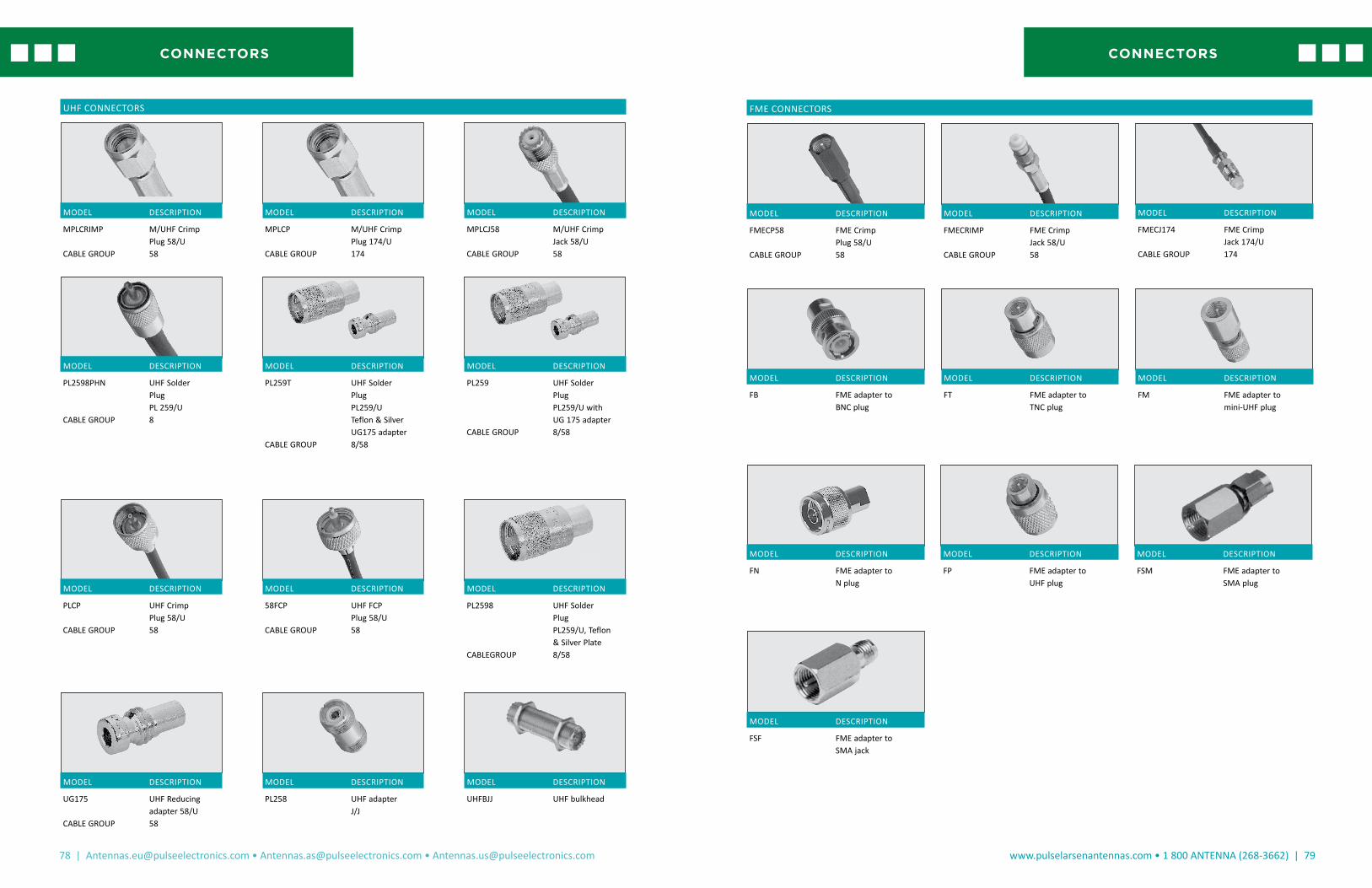
78 | [email protected] • [email protected] • [email protected]
www.pulselarsenantennas.com • 1 800 ANTENNA (268-3662) | 79
UHF CONNECTORS
MODEL DESCRIPTION
MPLCRIMP M/UHF Crimp Plug 58/UCABLE GROUP 58
MODEL DESCRIPTION
MPLCJ58 M/UHF Crimp Jack 58/UCABLE GROUP 58
MODEL DESCRIPTION
MPLCP M/UHF Crimp Plug 174/UCABLE GROUP 174
MODEL DESCRIPTION
PLCP UHF Crimp Plug 58/UCABLE GROUP 58
MODEL DESCRIPTION
PL259 UHF Solder Plug PL259/U with UG 175 adapterCABLE GROUP 8/58
MODEL DESCRIPTION
PL258 UHF adapter J/J
MODEL DESCRIPTION
UHFBJJ UHF bulkhead
MODEL DESCRIPTION
UG175 UHF Reducing adapter 58/UCABLE GROUP 58
MODEL DESCRIPTION
58FCP UHF FCP Plug 58/UCABLE GROUP 58
MODEL DESCRIPTION
PL2598 UHF Solder Plug PL259/U, Teflon & Silver PlateCABLEGROUP 8/58
MODEL DESCRIPTION
PL2598PHN UHF Solder Plug PL 259/UCABLE GROUP 8
MODEL DESCRIPTION
PL259T UHF Solder Plug PL259/U Teflon & Silver UG175 adapterCABLE GROUP 8/58
CONNECTORS
FME CONNECTORS
MODEL DESCRIPTION
FMECP58 FME Crimp Plug 58/UCABLE GROUP 58
MODEL DESCRIPTION
FMECJ174 FME Crimp Jack 174/UCABLE GROUP 174
MODEL DESCRIPTION
FB FME adapter to BNC plug
MODEL DESCRIPTION
FMECRIMP FME Crimp Jack 58/UCABLE GROUP 58
MODEL DESCRIPTION
FT FME adapter to TNC plug
MODEL DESCRIPTION
FP FME adapter to UHF plug
MODEL DESCRIPTION
FM FME adapter to mini-UHF plug
MODEL DESCRIPTION
FSM FME adapter to SMA plug
MODEL DESCRIPTION
FN FME adapter to N plug
MODEL DESCRIPTION
FSF FME adapter to SMA jack
CONNECTORS

80 | [email protected] • [email protected] • [email protected]
www.pulselarsenantennas.com • 1 800 ANTENNA (268-3662) | 81
MODEL DESCRIPTIONA4 BSA/BA/SO-239 to NMO
mount adapter
MODEL DESCRIPTION6 x 32 Set Screws8 x 32 Set Screws
MODEL DESCRIPTIONBAHEXNUT Hex nut for BA
MODEL DESCRIPTIONBANOHARDWARE Bulkhead mount adapter
without hardware
MODEL DESCRIPTIONBALL1B Black teardrop rod tip for W490,
W540 tapered rodsBALL2B Black teardrop rod tip for Q and
NMOQ antennasBALL3B Black teardrop rod tip for .100
diameter non-tapered rodsBALL4 Rod tip WBQ800 antennas
MODEL DESCRIPTIONBA Bulkhead mount
adapter with hardware
MODEL DESCRIPTIONBATTBOLT Battery bolt with termi-
nals, 3/8” ring leads
MODEL DESCRIPTIONFB3BRACKET Mounting bracket and
hardware for blade and round FB antennas
MODEL DESCRIPTIONFB2BRACKET Mounting bracket
and hardware for FB2 series
PARTS/ACCESSORIES
MODEL DESCRIPTIONKGREINSTALL KG glassmount rein-
stallation kit die cut tape
MODEL DESCRIPTIONHSBLADE Replacemeng blades
for HS1
MODEL DESCRIPTIONHS1 3/4” hole saw fits 3/8” or
larger drills
MODEL DESCRIPTIONGROMMETS Qty 100 plastic grom-
met secures/ centers coax, 3/4” hole
MODEL DESCRIPTIONHP34 Plastic hole plug for 3/4”
holeHP38 Plastic hole plug for 3/8”
hole
MODEL DESCRIPTIONKGREINSTALLDC KG glass mount
reinstallation kit die cut tape
MODEL DESCRIPTIONKGSWIVEL.073 KG swivel mount
assembly, .073 diaKGSWIVEL.100 KG swivel mount
assembly, .100 dia
MODEL DESCRIPTIONMM34 Rectangular mag mount
housing, 3/4” hole
MODEL DESCRIPTIONNMOBRASSRING Nickel plated brass
ring for NMO and NMOHF mounts
PARTS/ACCESSORIES

82 | [email protected] • [email protected] • [email protected]
www.pulselarsenantennas.com • 1 800 ANTENNA (268-3662) | 83
MODEL DESCRIPTIONOCBRACKET 3” Tall bracket for ceil-
ing or wall mount, Cool Grey
MODEL DESCRIPTIONNMOTEST1 Test adapter for NMO
mount
MODEL DESCRIPTIONHFCENTERCONTACT NMOHF Center Contacts
and Insulators - 10 each
MODEL DESCRIPTIONNMOCAPB Rain cap for NMO
mount
MODEL DESCRIPTIONQCONE.073 Chrome Q cone / Q
base, .073 dia.QCONE.100 Chrome Q cone / Q
base, .100 dia.QCONE.125 Chrome Q cone / Q
base, .125 dia.
MODEL DESCRIPTIONOLMMNT O ring for LM mountONMOANT O ring for NMO
antennas/basesONMOMNT O ring for NMO mountOPOMNT O ring for PO mount
MODEL DESCRIPTIONQCONE.073B Black Q cone / Q
base, .073 dia.QCONE.100B Black Q cone / Q
base, .100 dia.QCONE.125B Black Q cone / Q
base, .125 dia
MODEL DESCRIPTIONRGFB1ANT Rubber gaskets for FB1
antenna
MODEL DESCRIPTIONRGNMOANT Rubber gasket for NMO
coil/basesRGPOMNT Rubber gasket for PO
mounts
PARTS/ACCESSORIES
MODEL DESCRIPTIONRGOMANT Rubber gasket for OM
bases
MODEL DESCRIPTIONRGSS Rubber SuperSeal gasket for
MakroBlend® coils / bases
MODEL DESCRIPTIONSPRING Chrome shock springShock Spring QCONE Q Base.100 dia & wrench included
MODEL DESCRIPTIONSPANNER Spanner wrench for PO and
NMOK mounts
MODEL DESCRIPTIONWACLIP Mounting clips for
WA700/2700 Series - 2 per package
MODEL DESCRIPTIONSPRINGB Black shock springShock Spring QCONE.100B Q Cone.100 dia & wrench included
MODEL DESCRIPTIONWASUCTIONCUP Suction cup mounts for
WA700/2700 Series - 2 per package
MODEL DESCRIPTIONYAGIKITHD Mounting hardware for
2 1/2” pipe for YA3, YA5 and YA6 antennas
MODEL DESCRIPTIONTMB34 Trunk Mount Bracket
TBM34B Trunk Mount Bracket (Black)
PARTS/ACCESSORIES

84 | [email protected] • [email protected] • [email protected]
www.pulselarsenantennas.com • 1 800 ANTENNA (268-3662) | 85
RG-58U - Low Loss Dual Shield with Solid Center Conductor (UD
This is Larsen’s premium coax for 800 and 900 MHz applications. The solid center conductor (20 AWG) is easy to use with all connectors. Digital applications benefit from the 100% Duofoil aluminum shield. The shield is not glued to the dielectric making it easier to peel back for connector installation. The braid is 95% coverage. This cable is standard for most mount-ing kits over 800 MHz and can be special ordered with other frequencies. Uses stan-dard RG-58 connectors.
Recommended Applications
For all applications at 800 MHZ and above
Larsen Part Number: UD CoaxStocking Lengths: 1000’/Spool Cut to order
RG-213 - Stranded Bare Braid - Mil Spec QPI
This RG-8-sized cable uses a stranded cen-ter conductor with a polyethylene dielectric and PVC jacket. Built to Mil Specs this cable is used in all Larsen UHF/VHF products tar-geted for outdoor installation.
Recommended Applications
For lower frequency applications requiring high ruggedness.
Larsen Part Number: RG-213 Stocking Lengths: 500’ or 1000’/Spool Cut to order
RG-174 - Small Diameter Coax
RG-174 is the industry standard for appli-cations requiring a small diameter, highly flexible coax. Frequently used in mobile mag mount applications. Subject to higher losses at higher frequencies. Good per-formance for environmental variations but lower in overall ruggedness.
Recommended Applications
Mobile/Portable less than 900 MHz where flexibility and small diameter is important.
Larsen Part Number: RG-174Stocking Lengths: 1000’/Spool Cut to order
RG-58A/U - “Digi-Shield”™ Low Loss Braided Center
Employs two shields, consisting of a full aluminum/mylar wrap covered by a braid. This combination of shields, plus low-loss dielectric material and stranded center con-ductor makes an excellent choice for mobile applications. Performance features include low-loss and high flexibility. Uses standard RG-58 connectors.
Recommended Applications
Higher performance applications where lower loss and flexibly are important. Recommended for applications above 800 MHz.
Larsen Part Number: DS CoaxStocking Lengths: 1000’/Spool Cut to order
RG-58A/U - CX Standard Coax
The industry standard in quality, value-priced coax. Stranded center conductor offers good flexibility and long-life under most conditions. Not typically recom-mended for applications above 512 MHz due to higher losses. Uses standard RG-58 connectors.
Recommended Applications
General applications under 512 MHz. First choice for value priced coax.
Larsen Part Number: CX CoaxStocking Lengths: 1000’/Spool Cut to order
COAX TYPES/PART NUMBERS
COAXIAL CABLES
COAX SPECIFICATION COMPARISON
COAXIAL CABLES
TECHNICAL CHARACTERISTICS OF INSULATION AND JACKET COMPOUNDS
TEFLON
This material has excellent electrical properties, temperature range and chemical resistance. It is not suitable where subjected to nuclear radiation and does not have good high voltage characteristics. FEP Teflon is extrudable in a manner similar to PVC and polyethylene. This means long wire and cable lengths are available. TFE Teflon is extrudable in hydraulic ram-type process. Lengths are limited due to amount of material in the ram, thickness of the insulation and preform size. TFE must be extruded over a silver- or nickel-coated wire. The nickel- and silver-coated designs are rated 260° C and 200° C maximum, respectively. The cost of Teflon is approximately 8 to 10 times more per pound than PVC compounds.
POLYETHYLENE (SOLID AND FOAM)
A very good insulation in terms of electrical properties. Low dielectric constant, a stable dielectric constant over all frequencies, very high insulation resistance. In terms of flexibility, polyethylene can be rated stiff to very hard, depending on molecular weight and density — low-density being the most flexible, and high-density, high-molecular weight formulation being very hard. Moisture resistance is rated excellent. Correct Brown and Black formula-tions have excellent weather resistance. The dielectric constant is 2.3 for solid insulation and 1.64 for foam designs. Flame retardant formu-lations are available with dielectric constants ranging from about 1.7 for foam flame retardant to 2.58 solid flame retardant polyethylene.
PVC
Sometimes referred to as vinyl or polyvinyl chloride. Extremely high or low temperature properties cannot be found in one formulation. Certain formulations may have -55° C to +105° C rating. Other common vinyls may have -20° C to +60° C. There are many formulations for the variety of different applications. The many vari-eties of PVC also differ in pliability and electrical properties. The price range can vary accord-ingly. Typical dielectric constant values can vary from 3.5 to 6.5.
Nominal Temperature Range/Insulating and Jacketing Compounds
Normal Normal Special SpecialCompound Low High Low High
Polyethylene - Solid -60° C 80°C -- --
Polyethylene - Foam -60° C 80° C -- --
FEP Teflon -70° C 200° C -- --
PVC -20° C 80° C -55° C 105° C
TFE Teflon -70° C 260° C -- --
Comparative Properties of Insulation and Jacket
PVC Low-density PolyethyleneOxidation Resistance E EHeat Resistance G-E GOil Resistance F G-ELow Temperature Flexibility P-G EWeather, Sun Resistance G-E EOzone Resistance E EAbrasion Resistance F-G GElectrical Properties F-G EFlame Resistance E PNuclear Radiation Resistance F G-EWater Resistance F-G EAcid Resistance G-E G-EAlkali Resistance G-E G-EGasoline, Kerosene, Etc. (Aliphatic Hydrocarbons) Resistance P G-EBenzol, Toluol, Etc., (Aromatic Hydrocarbons) Resistance P-F PDegreaser Solvents (Halogenated Hydrocarbons) Resistance P-F GAlcohol Resistance G-E EUnderground Burial P-G G
P = Poor F = Fair G = Good E = Excellent

86 | [email protected] • [email protected] • [email protected]
www.pulselarsenantennas.com • 1 800 ANTENNA (268-3662) | 87
NOTESNOTES

CONTACT US TODAY!Call us at +1.800.ANTENNA
Visit our website at: pulselarsenantennas.com Connect with us on twitter: PulseLarsen1
Europe - FinlandAutomaatiotie 1, FI-90440 Oulunsalo. Tel: [email protected]
Europe - GermanyCampus Berliner AlleeBerliner Allee 65 D-64295Darmstadt GermanyTel: +49 173 659 85 [email protected]
ISO Manufacturing SiteNo 99. Huo Ju road, Suzhou new District, Jiangsu Province, Suzhou, China, PRC. Tel: [email protected]
Worldwide HeadquartersSan Diego, CA, USA15255 Innovation Drive #100San Diego, CA 92128+1-858-674-8100
Vancouver, WA, USA18110 SE 34th StreetSuite 250, Building 2Vancouver, WA 98683 Tel: [email protected]