software requirements specification (srs) …435cruise1/resources/srs_firstdraft_cruise1.pdftemplate...
TRANSCRIPT
Template based on IEEE Std 830-1998 for SRS. Modifications (content and ordering of information) have
been made by Betty H.C. Cheng, Michigan State University (chengb at chengb.cse.msu.edu)
Software Requirements Specification (SRS)
Cooperative Adaptive Cruise Control Project
Authors: Dan Sosnowski, Justin Vrooman, Jake Newsted, Max Ellison, Pat
O’Connell
Customer: William Milam
Instructor: Professor Betty Cheng
1 Introduction
This document provides the description and requirement specification for an embedded
vehicle system. The sections that follow use defined terminology and various modeling
techniques to describe the purpose and perspective of the proposed system. The sections
succinctly state the requirements of the system and to visually model its functionality
using various types of diagrams. Finally, a complete prototype of the system will is
introduced with instructions regarding its usage and sample scenarios representative of
the system.
1.1 Purpose
The purpose of this document is to validate that the proposed embedded vehicle system's
design meets customer and user needs and expectations using descriptive language,
modeling diagrams and prototyping. All parties participating in the project including but
not limited to the customers, the developers and the users should be able to pull from this
document the functionality, user expectations, constraints and requirements of the
proposed system.
1.2 Scope
Software-based electronic control systems are increasing being used in the automotive
industry to provide convenience and safety features to vehicle drivers and passengers,
with increasing levels of automation and control authority (Cheng). The embedded
vehicle system proposed in this document is an advanced cruise control system
henceforth referred to as a Cooperative Adaptive Cruise Control (CACC) system. The
application domain for this product is that of an embedded system for automotive
systems. The software specified in this document provides the benefits of added cruise
control convenience requiring lesser degrees of user action and decreased congestion on
vehicle roadways in a fully realized product environment. The CACC system will attempt
to maintain a constant speed as specified by the user unless an obstacle, such as a slower

Template based on IEEE Std 830-1998 for SRS. Modifications (content and ordering of information) have
been made by Betty H.C. Cheng, Michigan State University (chengb at chengb.cse.msu.edu)
moving vehicle, is encountered in which case the system will adjust its speed to follow
with a closing rate of 0 and a following gap as specified by the user. CACC vehicles have
the added benefits of communication with other CACC vehicles and roadway
infrastructure. A CACC system will have the ability to group with other CACC systems,
henceforth referred to as platoon or platooning. Platooned vehicles will work together for
the betterment of the platoon and the users of the roadway to keep traffic moving and
attempt to prevent roadway congestion. The system will not steer the vehicle in any way
for the user.
1.3 Definitions, acronyms, and abbreviations
CC – Cruise Control
ACC – Adaptive Cruise Control
CACC – Cooperative Adaptive Cruise Control
DSRC – Dedicated Short-Range Communication
CAN-bus – Controller-Area Network Bus
SRS – Software Requirements Specification
UI – User Interface
HTML – Hyper-Text Markup Language
GPS – Global Positioning System
UML – Unified Modeling Language
Platoon – A collection of 2 or more communicating vehicles moving in the same
direction with the same speed in the same lane.
Gap – The distance between the vehicle and the vehicle in front of it.
Target – Any object detected by the system as potentially having an impact on its
ability to perform as a CACC system.
Closing Rate – The rate at which the vehicle is approaching a target in front of it.
1.4 Organization
The rest of the document we will be giving explanation for the motivation behind
creating a CACC system, listing the upfront requirements and the high level designs that
resulted from them and then finally giving a functional web based prototype that models
how the system would perform in a real-life situation.
The remaining portion of the specification will be divided into four parts with subsections
for each part. The overall description will present the rationale behind developing such as
system and the functions that resulted from it. It will also outline the user and system
constraints that might be necessary for employing such a system. The specific
requirements section will enumerate the requirements set by the customer. We will then
present the specific UML diagrams that fulfill the requirements listed in the previous
section. Each diagram will be accompanied by a brief description for the high level

Template based on IEEE Std 830-1998 for SRS. Modifications (content and ordering of information) have
been made by Betty H.C. Cheng, Michigan State University (chengb at chengb.cse.msu.edu)
concepts in that diagram. Finally we will present a quick look at the prototype along with
instructions on how and where you can use it.
2 Overall Description
This section delivers an all-inclusive description of the CACC system providing a
perspective from which to view the system and to create context, a formal declaration of
all of the CACC functionality and expectations of a representative user of the system. All
constraints such as those related to the safety and the security of the system will be
discussed. Hardware, software, environmental and user related assumptions and
dependencies made by the design team and requirements deemed outside the scope of the
current system design are declared.
2.1 Product Perspective
In a world with a perpetually growing population there exists the problem of
overcrowding cities and congested roadways. Technology has presented us with the
opportunity to begin to solve one of these problems. By making our cars smarter we have
created methods of mitigating roadway congestion. Initially GPS units presented the
ability to warn the user of upcoming road congestion, giving them the option to avoid
being caught in stop and go traffic. What if GPS could be utilized in a different way, to
prevent congested roadways?
Cooperative Adaptive Cruise Control (CACC) is a cruise control system that utilizes
GPS, camera, radar and radio communication to create a platoon of vehicles working
together to prevent congestion by maintaining a continuous flow of traffic. CACC
requires specially equip vehicles and modern infrastructure to make this vision possible.
Additionally, CACC vehicles will be presented with obstacles such as sharing the
roadway with non-CACC/unintelligent cars, malfunctioning system hardware, weather
and environment conditions, security related concerns and other system constraints.
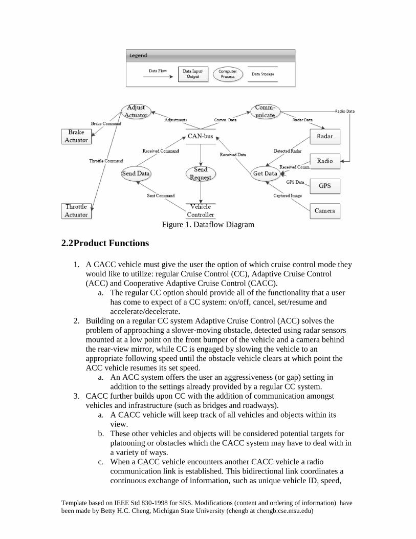
In embedded vehicle systems all communication between the system controller and other
vehicle subsystems occurs through the vehicles CAN-bus. Figure 1 shows CACC
communication being routed through the CAN-bus to the desired destination subsystems.
Template based on IEEE Std 830-1998 for SRS. Modifications (content and ordering of information) have
been made by Betty H.C. Cheng, Michigan State University (chengb at chengb.cse.msu.edu)
Figure 1. Dataflow Diagram
2.2 Product Functions
1. A CACC vehicle must give the user the option of which cruise control mode they
would like to utilize: regular Cruise Control (CC), Adaptive Cruise Control
(ACC) and Cooperative Adaptive Cruise Control (CACC).
a. The regular CC option should provide all of the functionality that a user
has come to expect of a CC system: on/off, cancel, set/resume and
accelerate/decelerate.
2. Building on a regular CC system Adaptive Cruise Control (ACC) solves the
problem of approaching a slower-moving obstacle, detected using radar sensors
mounted at a low point on the front bumper of the vehicle and a camera behind
the rear-view mirror, while CC is engaged by slowing the vehicle to an
appropriate following speed until the obstacle vehicle clears at which point the
ACC vehicle resumes its set speed.
a. An ACC system offers the user an aggressiveness (or gap) setting in
addition to the settings already provided by a regular CC system.
3. CACC further builds upon CC with the addition of communication amongst
vehicles and infrastructure (such as bridges and roadways).
a. A CACC vehicle will keep track of all vehicles and objects within its
view.
b. These other vehicles and objects will be considered potential targets for
platooning or obstacles which the CACC system may have to deal with in
a variety of ways.
c. When a CACC vehicle encounters another CACC vehicle a radio
communication link is established. This bidirectional link coordinates a
continuous exchange of information, such as unique vehicle ID, speed,

Template based on IEEE Std 830-1998 for SRS. Modifications (content and ordering of information) have
been made by Betty H.C. Cheng, Michigan State University (chengb at chengb.cse.msu.edu)
direction trajectory, GPS location and status message, between CACC
vehicles.
d. A link between CACC vehicles creates the opportunity for a platoon to be
created.
e. Drivers of each CACC vehicle within a potential platoon should be given
the opportunity to create a platoon via a prompt from the vehicle. The
driver may then either acknowledge this opportunity and accept this
proposition or ignore and continue to drive without interruption.
4. A CACC vehicle should be constantly broadcasting its information regardless of
whether CACC is engaged for the betterment of other CACC vehicles on the
roadway.
5. All system communication is routed through the system’s CAN-bus.
2.3 User Characteristics
It is expected that a user of the CACC system has driving experience including at least
minimal experience on highways. It is assumed that the user has a general understanding
of a regular cruise control system. A CACC system builds upon regular cruise control
adding various user conveniences; therefore, previous experience using a vehicle’s cruise
control system will be preferable. The system will require some basic user interaction and
it is expected that a user is comfortable performing various actions while also steering the
vehicle.
2.4 Constraints
In a safety-critical system such as a Cooperative Adaptive Cruise Control system, there
are certain constraints that must be met not only to ensure the safety of the user, but also
to ensure his or her relative comfort.
Upon start-up, the system must run a diagnostic check on each peripheral system. If any
of these systems are not fully-functioning, the corresponding modes of operation which
depend on these peripheral systems will not be available to the user.
All modes of the Cooperative Adaptive Cruise Control system (including standard Cruise
Control and Adaptive Cruise Control) will not be available to the user in situations where
the vehicle cannot maintain proper traction. The system, if allowed to attempt to operate
under such a condition, could jeopardize the safety of the user and his or her passengers.
Furthermore, acceleration within the system will be limited to three meters per second
squared, whether in the positive or negative direction. This constraint is necessary to
prevent undue jerkiness and will help maintain the comfort of the user.
2.5 Assumptions and Dependencies
It is assumed that our users will have access to a properly functioning vehicle with a
sufficient power source (such as gasoline and/or a charged battery). Furthermore, it is

Template based on IEEE Std 830-1998 for SRS. Modifications (content and ordering of information) have
been made by Betty H.C. Cheng, Michigan State University (chengb at chengb.cse.msu.edu)
assumed that our users are at least somewhat experienced drivers and understand the
basic tenets of cruise control and traffic.
Additionally, it is assumed, when considering the operation of our Cooperative Adaptive
Cruise Control system, that all of the previously-listed constraints are met and that the
system is operating in an environment in which the full functionality of the system is
possible.
2.6 Approportioning of Requirements
Upon discussion with the customer, it has been established that certain requirements and
functionalities are deemed to be beyond the scope of this iteration of the system. These
requirements and functionalities may be addressed and detailed in future releases.
Integration of the Cooperative Adaptive Cruise Control system with vehicle steering is
beyond the scope of this project currently. Whether for lane-changing, lane-maintaining,
or some other unspecified functionality, any integration of this sort is deemed outside the
project’s scope and will consequently be ignored.
3 Specific Requirements
General Requirements
1. The CACC system shall include the following entities
1.1. A vehicle controller
1.2. At least one camera
1.3. Radar
1.4. Radar Transponder
1.5. Radio
1.6. GPS
1.7. Driver
1.8. User Interface
1.9. Graphical Display
2. The CACC system shall have the following states
2.1. Full Cooperative Adaptive Cruise Control
2.2. Adaptive Cruise Control
2.3. “Dumb” Cruise Control
2.4. The system is disengaged.
3. Any actuator used by the CACC system shall be available for use by any other
system.
4. Requirements to engage the system for different modes
4.1. General
4.1.1. The system shall not engage when under 25 mph.

Template based on IEEE Std 830-1998 for SRS. Modifications (content and ordering of information) have
been made by Betty H.C. Cheng, Michigan State University (chengb at chengb.cse.msu.edu)
4.2. CACC
4.2.1. The system shall have full health, i.e. all systems must be functioning
properly.
4.3. ACC
4.3.1. The system shall enter ACC mode upon failure of radio communication
4.4. Normal Cruise
4.4.1. The system shall enter Normal Cruise mode upon failure of the radar and
radio systems.
5. The system shall be able to be disengaged in the following manners
5.1. The brakes are depressed by the driver
5.2. A press of the “Decline/Cancel” button
5.3. Failure modes, imminent crash
5.4. Going through the gears on auto shift
6. The system shall broadcast its information (see “RADIOCOMM”) once every
second.
6.1. The system shall also broadcast this packet of information upon the system
sensing these events.
6.1.1. The loss of tire pressure
6.1.1.1. This will cause a platoon to break if the vehicle is in a platoon.
6.1.2. The engaging of a turn signal
6.1.2.1. This will cause a platoon to break if the vehicle is in a platoon.
6.1.3. The detection of an imminent crash.
7. The system shall respond to the detection of an imminent crash in the following
manner.
7.1. The system shall pretension seatbelts (i.e. the seatbelts will be locked and pulled
tight).
7.2. The system shall pre-calculate airbag deployment, by using the weight and mass
of the person occupying the seat.
7.3. The system shall pre-pressure the brakes such that the slightest touch of the brake
pedal fully engages them.
7.4. The system shall disengage.
7.5. The system shall warn the user by means of a series of beeps and flashing LED’s.
8. The system shall use static memory allocation and not use the dynamic allocation of
memory.
9. The system shall maintain data for 0 to 256 objects it detects in the world.
Vehicle Controller Requirements
10. The vehicle controller is responsible for building the packets sent over the radio
communication links.
11. The vehicle controller is responsible for keeping track of the data for the 0 to 256
different objects it can detect.
Template based on IEEE Std 830-1998 for SRS. Modifications (content and ordering of information) have
been made by Betty H.C. Cheng, Michigan State University (chengb at chengb.cse.msu.edu)
12. The vehicle controller is what decides the current speed is based on the set target
speed and the information from the objects detected in our world.
13. The vehicle controller is responsible for sending the commands to accelerate and
decelerate based on its world.
14. The vehicle controller determines a priority for each object sensed by our different
sensing entities.
Camera
15. The camera shall have a wide angle lens.
16. The camera shall contain functionality to detect distance based on images.
Radar
17. The Radar utilized by the system shall have a 180 degree field of view.
18. The range of the radar shall be 150 ft.
19. There shall be a single radar mounted low on the front bumper of the vehicle.
Radar Transponder
20. The radar transponder shall set up radio communication links upon request
Radio Communication
21. The radio communication system shall use Directed short-range communications
(DSRC), an offshoot of 802.11 approved by the FAA, to broadcast its’ information to
other vehicles.
22. The radio communication shall continue even when the system is turned off by the
user.
23. The radio communication shall broadcast vehicle information using DSRC over
communication links initially set up by the radio transponder.
24. The radio communication shall not be reliable, i.e. there will be no “acks” or “nacks”.
25. The vehicle information shall be broadcasted once per second to accommodate the
unreliable communication links.
26. The packet sent and received by the radio communication link shall have this
structure
26.1. Vehicle Identification (for both the sender and receiver).
26.2. The vehicles’ speed.
26.3. The heading (direction), that the vehicle is traveling.
26.4. The GPS latitude and longitude of the vehicle.
26.5. A status message, which can be used to alert other cars of different scenarios.
GPS
27. The GPS system shall include topographic data along with GPS data in its repository.
28. The GPS system shall maintain the following information about the vehicle
28.1. The vehicle position
28.2. The vehicle heading.

Template based on IEEE Std 830-1998 for SRS. Modifications (content and ordering of information) have
been made by Betty H.C. Cheng, Michigan State University (chengb at chengb.cse.msu.edu)
28.3. The vehicle speed.
Graphical User Interface (GUI)
29. The GUI shall be displayed on the dashboard of the car by the speedometer and any
other gauges.
30. The GUI shall display the following information
30.1. The GUI shall display the current mode of the cruise control system, i.e. CACC,
ACC, etc.
30.2. The GUI shall display the target speed of the vehicle.
30.3. The GUI shall display the gap setting if the system is in the CACC, or ACC
modes.
30.4. The GUI shall display a visual representation of the vehicle and radar bars to
visually represent the gap setting.
30.5. The GUI shall display any requests to join a platoon, with the options to agree
or disagree.
30.6. The GUI shall alert the driver of any imminent crashes with a warning message,
flashing lights, and a series of beeps.
Driver
31. The driver shall be able to interact with the GUI interface by means of buttons located
on the steering wheel.
32. These buttons shall include
32.1. Gap Setting Switch
32.1.1. This switch shall control the following distance of the system when the
system is engaged with CACC or ACC with the following options
32.1.1.1. Aggressive
32.1.1.2. Moderate
32.1.1.3. Passive
32.1.1.4. Normal Cruise Control
32.2. “Decline/Cancel”
32.2.1. This button shall decline a prompted message, or disengage the cruise
control while the system is still on.
32.3. “Set/-“
32.3.1. The “Set/-“ button shall set the target speed of the cruise control system
when the system is currently on and disengaged.
32.3.2. The “Set/-“ button shall decrease the target speed when the system is on
and engaged.
32.4. “Res/+”
32.4.1. The “Res/+” button shall resume a set speed if a prior speed has been set
by the driver and the system is on and disengaged

Template based on IEEE Std 830-1998 for SRS. Modifications (content and ordering of information) have
been made by Betty H.C. Cheng, Michigan State University (chengb at chengb.cse.msu.edu)
32.4.2. The “Res/+” button shall increase the target speed of the vehicle provided
the system is on currently engaged.
32.5. “Accept”
32.5.1. The “Accept” button shall be used to accept requests for platooning from
other cars.
32.5.2. The vehicle shall not enter “Platoon” mode without the acknowledgment
of the driver within 5 seconds of receiving the prompt.
32.6. “On/Off”
32.6.1. The “On/Off” button shall turn the system on and off, and enter the best
available version of the cruise control system, which is determined by the
health of the system
32.6.2. The “On/Off” button shall not however end the radio communication
between cars.
4 Modeling Requirements
This section will visually depict the proposed CACC system using a series of different
modeling techniques. Typical representative uses of the system will be shown through
UML use case diagrams. A high-level domain model represented as a UML class
diagram is presented to show the interactions between various system components and
how data will be stored within the system. Sequence diagrams for various use cases are
then presented to show how the interactions between system components take place to
implement a desired use case. Finally, models representing all possible states that the UI
and system can transition between are displayed using state diagrams.
4.1 Use Case Diagram
Figure 2 is a UML use case diagram that represents typical use cases of the CACC
system.

Template based on IEEE Std 830-1998 for SRS. Modifications (content and ordering of information) have
been made by Betty H.C. Cheng, Michigan State University (chengb at chengb.cse.msu.edu)
Figure 2. Use Case Diagram
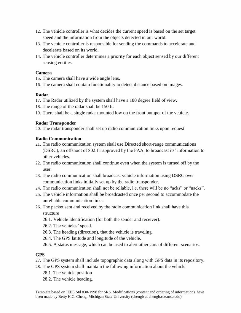
4.2 Class Diagram
Figure 3 is a UML class diagram that represents how systems will interact and how data
will be stored. Later in section 4 sequence diagrams will be used to relate use cases to the
class diagram and show how system functions and data properties interact to make the
use cases a reality. Included with the UML class diagram are data dictionaries which
further describe the functions and data attributes defined in the class diagram.
Template based on IEEE Std 830-1998 for SRS. Modifications (content and ordering of information) have
been made by Betty H.C. Cheng, Michigan State University (chengb at chengb.cse.msu.edu)
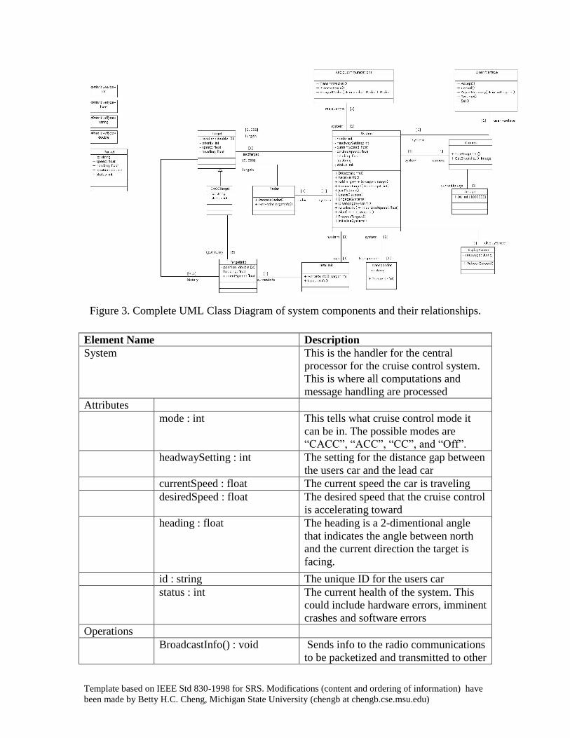
Figure 3. Complete UML Class Diagram of system components and their relationships.
Element Name Description
System This is the handler for the central
processor for the cruise control system.
This is where all computations and
message handling are processed
Attributes
mode : int This tells what cruise control mode it
can be in. The possible modes are
“CACC”, “ACC”, “CC”, and “Off”.
headwaySetting : int The setting for the distance gap between
the users car and the lead car
currentSpeed : float The current speed the car is traveling
desiredSpeed : float The desired speed that the cruise control
is accelerating toward
heading : float The heading is a 2-dimentional angle
that indicates the angle between north
and the current direction the target is
facing.
id : string The unique ID for the users car
status : int The current health of the system. This
could include hardware errors, imminent
crashes and software errors
Operations
BroadcastInfo() : void Sends info to the radio communications
to be packetized and transmitted to other

Template based on IEEE Std 830-1998 for SRS. Modifications (content and ordering of information) have
been made by Betty H.C. Cheng, Michigan State University (chengb at chengb.cse.msu.edu)
vehicles
ReceiveInfo() : void Gets packets sent to the users vehicle
from the radio communications
AddTarget() : void Uses ProcessTargets to determine if a
target is eligible to be added to the array
of targets
RemoveTarget() : void Uses ProcessTargets to determine if a
target is no longer eligible to be a target.
It then removes it from the array
UpdateTarget() : void The system updates each targets info in
the array of targets
JoinPlatoon() : void The system updates the cruise control
mode, sends out information via
transponder to other platoon vehicles
and updates the target array to include
CACC targets
LeavePlatoon() : void The system sets the mode to a non-
CACC state and no longer listens to
CACC specific information broadcast
from other vehicles
EngageSystem() : void Checks if the system is able to engage
cruise control and sets the mode flag to
the appropriate cruise control mode
DisengageSystem() : void Turns off all cruise control functions
and sets the mode to “Off”. This can be
called because the user turns off cruise
control, the car turns off or there is
software or hardware errors
Accelerate(
desiredSpeed:float) : void
This sets the desiredSpeed to the new
desired speed
Alert(status:int) : void This prompts the system to display a
status error (i.e. too slow to engage) or
an event notification (i.e. join platoon)
ProcessTarget() : void This checks the camera, radar and GPS
to check if targets are relevant, able to
join or can be removed from the target
array
InitializeSystem() : void This function is called on setup and
initializes all sub-components
Relationships The system has one RadioCommunication, Camera, Transponder, GPS
and Radar device. The system requests information from each of these to
apply updates to acceleration and other relevant CACC information. The
system also keeps track of an array of up to 255 targets. The system
processes each target’s info and updates it. It also keeps a separate
special target that represents the lead target.
UML N/A

Template based on IEEE Std 830-1998 for SRS. Modifications (content and ordering of information) have
been made by Betty H.C. Cheng, Michigan State University (chengb at chengb.cse.msu.edu)
Extensions
Element Name Description
Camera A class that handles the camera data and
camera functions
Attributes
Operations
TakeSnapshot() : void Tells the camera to take a snapshot and
store it to the currentImage
GetSnapshot() : Image Returns the currentImage to the System.
Relationships The camera keeps a handler for the current system it is registered to and
an Image that represents the current image
UML
Extensions
N/A
Element Name Description
Image This is a container for a bitmap
Attributes
bit[1000000] : int This is an array of one million integers
that represent a 1000x1000 pixel picture
Operations
Relationships This holds a camera that owns the current image
UML
Extensions
N/A
Element Name Description
Transponder This sends out vehicle information to
other cars when prompted by a
following vehicle
Attributes
id : string The current car ID
Operations
TransmitInfo() : void Broadcasts the vehicle id to a car
following the users car
Relationships The transponder holds the current system that is controlling the
transponder
UML
Extensions
N/A
Element Name Description
Packet This is the packet structure that is
transmitted to other vehicles in a

Template based on IEEE Std 830-1998 for SRS. Modifications (content and ordering of information) have
been made by Betty H.C. Cheng, Michigan State University (chengb at chengb.cse.msu.edu)
platoon
Attributes
id : string The vehicles current unique ID
speed : float The current speed of the vehicle
heading : float The heading of the vehicle. This is the
angle between north and the vehicle’s
current direction
location : double[3] The location of the vehicle in the format
of: (longitude, latitude, elevation).
status : int The current status of the users car
Operations
Relationships This has no relations, but it is used by the radio communications
UML
Extensions
N/A
Element Name Description
DisplayScreen A handler for the screen. This helps
refresh and display the current messages
Attributes
message : string The message that is displayed on the
screen
Operations
RefreshScreen() : void Refreshes the screen and displays any
new messages
Relationships It holds the current system that controls the screen
UML
Extensions
N/A
Element Name Description Radio Communications The radio communications class
represents the radio unit which will broadcast packets of information over DSRC links to other vehicles.
Attributes N/A N/A Operations TransmitPacket(packet :
Packet) : void This function will take in a packet it and broadcast it using a previously established DSRC link.
ProcessRadio ( void ): Packet
This function will first decrypt the packet received over the DSRC link, and then builds a packet that will be sent to the system.

Template based on IEEE Std 830-1998 for SRS. Modifications (content and ordering of information) have
been made by Betty H.C. Cheng, Michigan State University (chengb at chengb.cse.msu.edu)
EncryptPacket( packet : Packet) : Packet
This function will take in a packet and using a predetermined algorithm, build an encrypted version of the packet to be broadcast over the DSRC link.
Relationships The RadioCommunications class has a one to one association between it and our system class, which will represent the CAN-bus link between the two physical systems.
UML Extensions
N/A
Element Name Description Target The target class is the container for
the information that is stored about a target we are tracking using the camera or radar.
Attributes location:double[3] This value is the calculated location of
the target based on the history of sensed information along with the time elapsed since our last update.
priority:int This attribute represents the priority that the system has determined for the target. This priority will be used to make a decision on what our cars reaction will be.
speed:float This attribute represents the calculated speed of the target. The system will be the one updating this information.
heading:float This attribute represents the bearing of the vehicle, and is a 2 dimensional angle which represents the angle between north and the current heading of the target vehicle.
Operations N/A N/A Relationships The association between this class and the system class represents
that the system will contain 0 to 255 different targets. The target class also is the base class for our CACCTarget class. The target class will also contain a history of different target information so that predictions can be made about the actions of the target.
UML Extensions
N/A
Template based on IEEE Std 830-1998 for SRS. Modifications (content and ordering of information) have
been made by Betty H.C. Cheng, Michigan State University (chengb at chengb.cse.msu.edu)
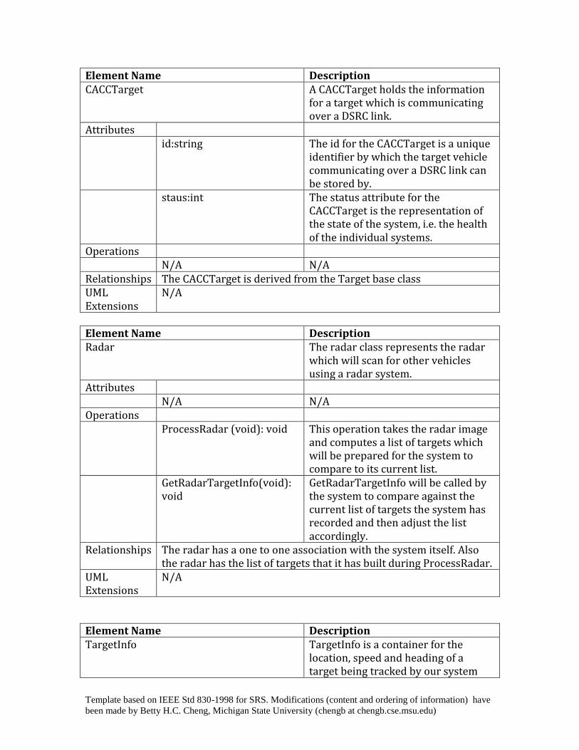
Element Name Description CACCTarget A CACCTarget holds the information
for a target which is communicating over a DSRC link.
Attributes id:string The id for the CACCTarget is a unique
identifier by which the target vehicle communicating over a DSRC link can be stored by.
staus:int The status attribute for the CACCTarget is the representation of the state of the system, i.e. the health of the individual systems.
Operations N/A N/A Relationships The CACCTarget is derived from the Target base class UML Extensions
N/A
Element Name Description Radar The radar class represents the radar
which will scan for other vehicles using a radar system.
Attributes N/A N/A Operations ProcessRadar (void): void This operation takes the radar image
and computes a list of targets which will be prepared for the system to compare to its current list.
GetRadarTargetInfo(void): void
GetRadarTargetInfo will be called by the system to compare against the current list of targets the system has recorded and then adjust the list accordingly.
Relationships The radar has a one to one association with the system itself. Also the radar has the list of targets that it has built during ProcessRadar.
UML Extensions
N/A
Element Name Description TargetInfo TargetInfo is a container for the
location, speed and heading of a target being tracked by our system
Template based on IEEE Std 830-1998 for SRS. Modifications (content and ordering of information) have
been made by Betty H.C. Cheng, Michigan State University (chengb at chengb.cse.msu.edu)
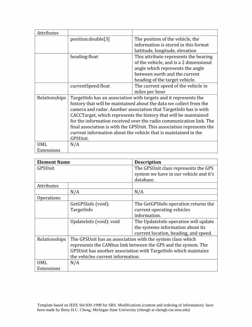
Attributes position:double[3] The position of the vehicle, the
information is stored in this format lattitude, longitude, elevation
heading:float This attribute represents the bearing of the vehicle, and is a 2 dimensional angle which represents the angle between north and the current heading of the target vehicle.
currentSpeed:float The current speed of the vehicle in miles per hour
Relationships TargetInfo has an association with targets and it represents the history that will be maintained about the data we collect from the camera and radar. Another association that TargetInfo has is with CACCTarget, which represents the history that will be maintained for the information received over the radio communication link. The final association is with the GPSUnit. This association represents the current information about the vehicle that is maintained in the GPSUnit.
UML Extensions
N/A
Element Name Description GPSUnit The GPSUnit class represents the GPS
system we have in our vehicle and it’s database.
Attributes N/A N/A Operations GetGPSInfo (void):
TargetInfo The GetGPSInfo operation returns the current operating vehicles information.
UpdateInfo (void): void The UpdateInfo operation will update the systems information about its current location, heading, and speed.
Relationships The GPSUnit has an association with the system class which represents the CANbus link between the GPS and the system. The GPSUnit has another association with TargetInfo which maintains the vehicles current information.
UML Extensions
N/A

Template based on IEEE Std 830-1998 for SRS. Modifications (content and ordering of information) have
been made by Betty H.C. Cheng, Michigan State University (chengb at chengb.cse.msu.edu)
4.3 Sequence Diagrams
Use case – Turn system off Actors: User, User Interface, System, Display Screen Type: Primary, essential Description: User hits the "On/Off" switch while the system is engaged to
initiate the logoff sequence. The system will give speed control back to the user, update the
Use cases: Turn System On
Use case – Turn system on Actors: User, User Interface, System, Display Screen Type: Primary, essential Description: User presses the "On/Off" button on the user interface while
the system is not engaged to initiate the startup sequence. The system will check its health to see if ACC or CACC can be engaged. Either way, the display screen is updated to reflect success or failure.
Use cases: User must not be logged in already
Template based on IEEE Std 830-1998 for SRS. Modifications (content and ordering of information) have
been made by Betty H.C. Cheng, Michigan State University (chengb at chengb.cse.msu.edu)
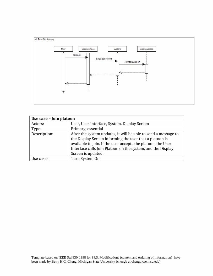
Use case – Join platoon Actors: User, User Interface, System, Display Screen Type: Primary, essential Description: After the system updates, it will be able to send a message to
the Display Screen informing the user that a platoon is available to join. If the user accepts the platoon, the User Interface calls Join Platoon on the system, and the Display Screen is updated.
Use cases: Turn System On
Template based on IEEE Std 830-1998 for SRS. Modifications (content and ordering of information) have
been made by Betty H.C. Cheng, Michigan State University (chengb at chengb.cse.msu.edu)
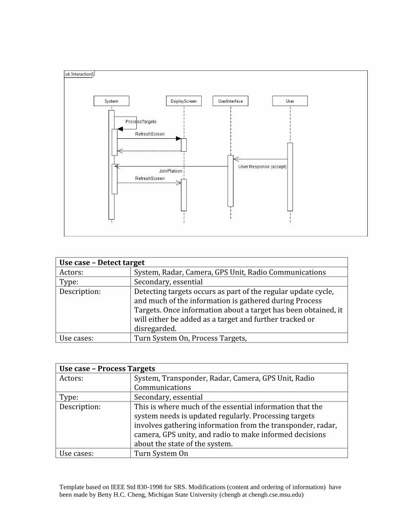
Use case – Detect target Actors: System, Radar, Camera, GPS Unit, Radio Communications Type: Secondary, essential Description: Detecting targets occurs as part of the regular update cycle,
and much of the information is gathered during Process Targets. Once information about a target has been obtained, it will either be added as a target and further tracked or disregarded.
Use cases: Turn System On, Process Targets,
Use case – Process Targets Actors: System, Transponder, Radar, Camera, GPS Unit, Radio
Communications Type: Secondary, essential Description: This is where much of the essential information that the
system needs is updated regularly. Processing targets involves gathering information from the transponder, radar, camera, GPS unity, and radio to make informed decisions about the state of the system.
Use cases: Turn System On

Template based on IEEE Std 830-1998 for SRS. Modifications (content and ordering of information) have
been made by Betty H.C. Cheng, Michigan State University (chengb at chengb.cse.msu.edu)
Use case – Get GPS location Actors: System, GPS Unit Type: Secondary, essential Description: During the Process Targets call on System, each target has its
GPS information retrieved. Use cases: Turn System On, Process Targets
Figure #.
4.4 State Diagrams
Figure 8 depicts the states which the user interface may enter and the transitions that take
place to move between each state. Figure 9 depicts the states which the system can enter
and the transitions to that take place to move between each state.

Template based on IEEE Std 830-1998 for SRS. Modifications (content and ordering of information) have
been made by Betty H.C. Cheng, Michigan State University (chengb at chengb.cse.msu.edu)
Figure 8. State Machine for UI.
Figure 9. State Machine for System.

Template based on IEEE Std 830-1998 for SRS. Modifications (content and ordering of information) have
been made by Betty H.C. Cheng, Michigan State University (chengb at chengb.cse.msu.edu)
5 Prototype
The prototype provides a simulation of how cooperative adaptive cruise control behaves
in various situations. The user will be able to select if the car is alone, following a car, or
is in a platoon. The user is able to interact with the steering wheel controls to perform
various operations on the system that impact how the user’s car performs. Depending on
how each player would act in a real world situation, the simulation will provide an
appropriate output in the form of a visual representation of how a typical CACC system
should perform. The visual output is shown in both a LCD screen on the dashboard and
on a “window” that shows what is going on outside of the vehicle.
5.1 How to Run Prototype
The simulation is implemented in Unity and deployed for use on the web. Unity is a
game engine that creates interactive games that can be deployed on various platforms
including the web. Products deployed on the web are identical to products deployed on
any other system. Supported browsers for products deployed this way are Internet
Explorer, Safari and Mozilla Firefox. The only necessary download is an ~3 MB plugin
that auto installs and works instantly.
Figure 10. This scenario represents a standard CACC situation. The right part of the LCD
screen displays pertinent information regarding the platoon and how your car is behaving
inside the platoon. The current speed represents the speed that the platoon is currently
traveling at. The line below that indicates if you are in CACC, ACC or CC mode.
Depending on the mode you are in, the remaining information may or may not be
available to the user. For instance, if you are in CACC mode you will be displayed the
current number of cars in your platoon, but if you are in ACC or CC then that information
is not applicable since there is no communication between local vehicles. The line below
the platoon information is the gap setting. This is applicable to CACC and ACC and
indicates how close you are following to the car directly ahead of you. In this case you
are following at the average distance, represented by a “moderate” rating.
Template based on IEEE Std 830-1998 for SRS. Modifications (content and ordering of information) have
been made by Betty H.C. Cheng, Michigan State University (chengb at chengb.cse.msu.edu)
Figure 10.
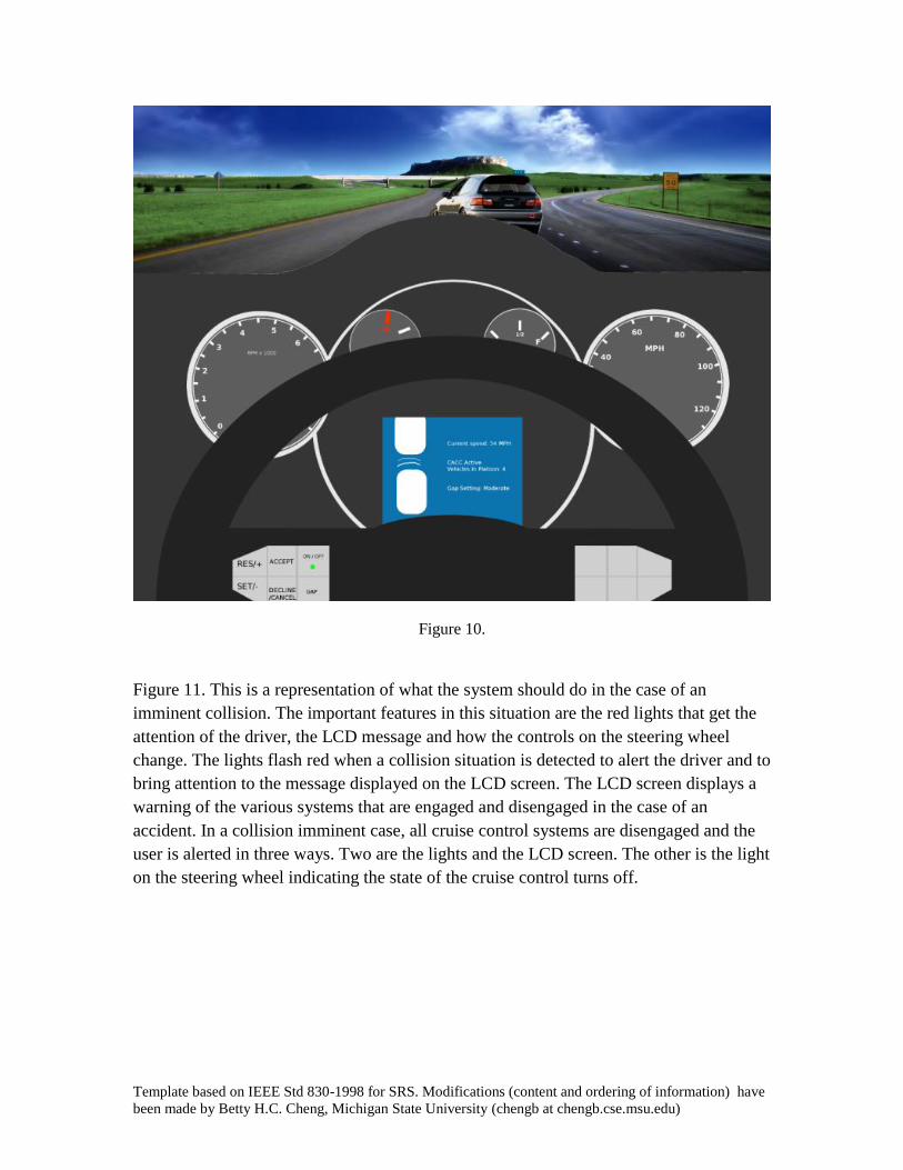
Figure 11. This is a representation of what the system should do in the case of an
imminent collision. The important features in this situation are the red lights that get the
attention of the driver, the LCD message and how the controls on the steering wheel
change. The lights flash red when a collision situation is detected to alert the driver and to
bring attention to the message displayed on the LCD screen. The LCD screen displays a
warning of the various systems that are engaged and disengaged in the case of an
accident. In a collision imminent case, all cruise control systems are disengaged and the
user is alerted in three ways. Two are the lights and the LCD screen. The other is the light
on the steering wheel indicating the state of the cruise control turns off.

Template based on IEEE Std 830-1998 for SRS. Modifications (content and ordering of information) have
been made by Betty H.C. Cheng, Michigan State University (chengb at chengb.cse.msu.edu)
Figure 11.
Figure 12. If a platoon is detected and the CACC system decides that it is a valid platoon
for your car to join, the user is prompted with a message displayed on the LCD screen
asking if the user wants to join the platoon. This message has a time out period and goes
away after 15 seconds. The user can accept the platoon invitation by pressing the
“Accept” button on the steering wheel or decline using the “Decline/Cancel” button. If
the message times out then after a two minute period if the car is still in the vicinity of the
platoon the user will be prompted again if they want to join. Only if the user pressed
“Decline/Cancel” will the message stop appearing.
Template based on IEEE Std 830-1998 for SRS. Modifications (content and ordering of information) have
been made by Betty H.C. Cheng, Michigan State University (chengb at chengb.cse.msu.edu)
Figure 12.
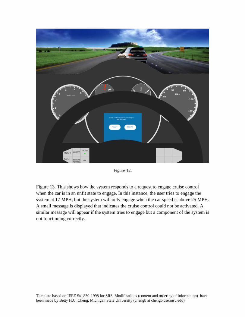
Figure 13. This shows how the system responds to a request to engage cruise control
when the car is in an unfit state to engage. In this instance, the user tries to engage the
system at 17 MPH, but the system will only engage when the car speed is above 25 MPH.
A small message is displayed that indicates the cruise control could not be activated. A
similar message will appear if the system tries to engage but a component of the system is
not functioning correctly.

Template based on IEEE Std 830-1998 for SRS. Modifications (content and ordering of information) have
been made by Betty H.C. Cheng, Michigan State University (chengb at chengb.cse.msu.edu)
Figure 13.
5.2 Sample Scenarios
1. You are driving on the highway going 61 MPH following a line of cars with CACC
capabilities. You are informed that you can join a platoon and you accept. Your car
then displays information regarding the speed you are going along with a visual
representation of how close you are following the lead car. You change your gap
setting to aggressive and the car accelerates to close the gap to the adjusted setting.
2. The car in front of you takes an exit off of the highway. The platoon is broken up, but
the system prompts you to join the platoon that was ahead of the car that left. You
chose to accept and your car accelerates to catch up to the CACC platoon.
3. You go some distance when there is an accident up ahead. The lead car slows down
and the entire platoon is notified and slows down uniformly. After the lead car clears
the accident, the chain of cars accelerates uniform with the lead car again. After the
lead car reaches the original set speed the chain of cars stop accelerating and the
platoon resumes a normal status.

Template based on IEEE Std 830-1998 for SRS. Modifications (content and ordering of information) have
been made by Betty H.C. Cheng, Michigan State University (chengb at chengb.cse.msu.edu)
4. You exit the highway onto a back road. You set the cruise control to go 45 MPH in
ACC. The system maintains a constant speed through the entire road. All of a sudden
a deer jumps in front of your car and the ACC detects the obstacle ahead. The system
deems the situation an imminent collision and turns off the ACC and prepares the car
for impact. The user is given an indication that the collision is imminent and gives a
message that declares the systems that are enabled and disabled as well as a warning
light that brings attention to the LCD screen. The user brakes in time and only gets
minor bumper damage, however the radar is damaged as well.
5. The user gets back to driving home and tries to activate the cruise control again. The
system detects that the radar is not operational and indicates that the cruise control
cannot be activated. The user then continues to drive without ACC until they get
home. The ACC won’t be able to activate until the radar is fixed again.
6 References
[1] Cheng, Dr. Better. "Cooperative Adaptive Cruise Control."
http://www.cse.msu.edu/%7Ecse435/Projects/F2011/Descriptions/CACC-MSU-
Ford.pdf. N.p., n.d. Web. 13 Nov. 2011.
<http://www.cse.msu.edu/%7Ecse435/Projects/F2011/Descriptions/CACC-MSU-
Ford.pdf>.
7 Point of Contact
For further information regarding this document and project, please contact Prof. Betty
H.C. Cheng at Michigan State University (chengb at cse.msu.edu). All materials in this
document have been sanitized for proprietary data. The students and the instructor
gratefully acknowledge the participation of our industrial collaborators.