social infrastructure business - hitachi global vessels and reactor internals from outside the...
TRANSCRIPT
HITACHI TECHNOLOGY2007-2008
Social InfrastructureBusiness
Social InfrastructureBusiness
Nuclear PowerThermal and Hydraulic Power
Electric Power DistributionPublic FacilitiesTransportationEnvironment
HITACHI TECHNOLOGY 2007–20084
HIGHLIGHTS 2007 2008
Global warming is a pressing international issue to be addressed. The main cause of global warming is supposedlycarbon dioxide and other greenhouse gases. Nuclear power generation, which discharges hardly any such green-house gases, is being reconsidered in various countries. Japan is one of them. The Nuclear Energy National Planpresented by the Agency for Natural Resources and Energy proposes the establishment of a nuclear fuel cycle and theaddition of next-generation nuclear power stations. Hitachi, Ltd. is enhancing and developing nuclear power technol-ogy that will play a central role in future energy.
Attempts to Realize a New Nuclear Power Station in Japan
HITACHI TECHNOLOGY 2007–20085
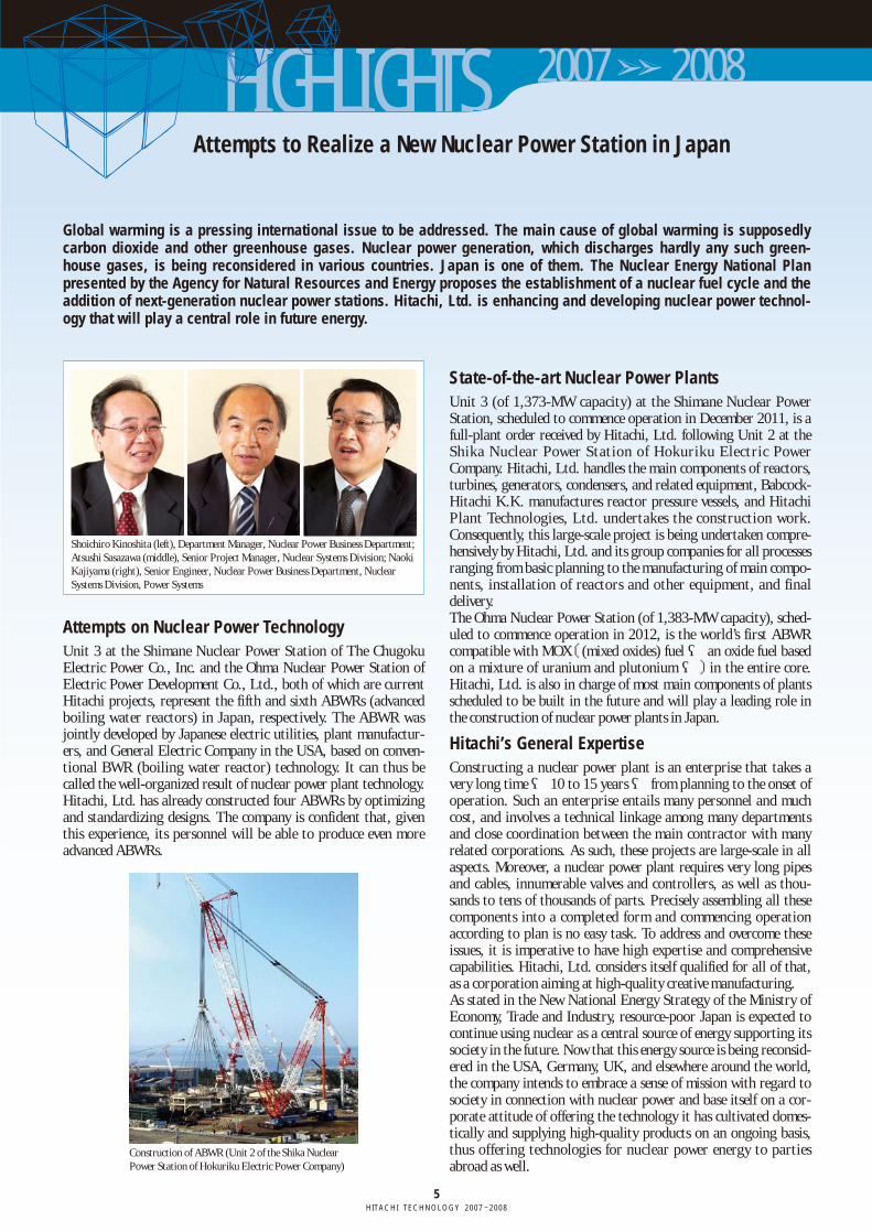
State-of-the-art Nuclear Power PlantsUnit 3 (of 1,373-MW capacity) at the Shimane Nuclear PowerStation, scheduled to commence operation in December 2011, is afull-plant order received by Hitachi, Ltd. following Unit 2 at theShika Nuclear Power Station of Hokuriku Electric PowerCompany. Hitachi, Ltd. handles the main components of reactors,turbines, generators, condensers, and related equipment, Babcock-Hitachi K.K. manufactures reactor pressure vessels, and HitachiPlant Technologies, Ltd. undertakes the construction work.Consequently, this large-scale project is being undertaken compre-hensively by Hitachi, Ltd. and its group companies for all processesranging from basic planning to the manufacturing of main compo-nents, installation of reactors and other equipment, and finaldelivery. The Ohma Nuclear Power Station (of 1,383-MW capacity), sched-uled to commence operation in 2012, is the world’s first ABWRcompatible with MOX〔(mixed oxides) fuel ― an oxide fuel basedon a mixture of uranium and plutonium ―〕in the entire core.Hitachi, Ltd. is also in charge of most main components of plantsscheduled to be built in the future and will play a leading role inthe construction of nuclear power plants in Japan.
Hitachi’s General Expertise Constructing a nuclear power plant is an enterprise that takes avery long time ― 10 to 15 years ― from planning to the onset ofoperation. Such an enterprise entails many personnel and muchcost, and involves a technical linkage among many departmentsand close coordination between the main contractor with manyrelated corporations. As such, these projects are large-scale in allaspects. Moreover, a nuclear power plant requires very long pipesand cables, innumerable valves and controllers, as well as thou-sands to tens of thousands of parts. Precisely assembling all thesecomponents into a completed form and commencing operationaccording to plan is no easy task. To address and overcome theseissues, it is imperative to have high expertise and comprehensivecapabilities. Hitachi, Ltd. considers itself qualified for all of that,as a corporation aiming at high-quality creative manufacturing.As stated in the New National Energy Strategy of the Ministry ofEconomy, Trade and Industry, resource-poor Japan is expected tocontinue using nuclear as a central source of energy supporting itssociety in the future. Now that this energy source is being reconsid-ered in the USA, Germany, UK, and elsewhere around the world,the company intends to embrace a sense of mission with regard tosociety in connection with nuclear power and base itself on a cor-porate attitude of offering the technology it has cultivated domes-tically and supplying high-quality products on an ongoing basis,thus offering technologies for nuclear power energy to partiesabroad as well.
Attempts on Nuclear Power TechnologyUnit 3 at the Shimane Nuclear Power Station of The ChugokuElectric Power Co., Inc. and the Ohma Nuclear Power Station ofElectric Power Development Co., Ltd., both of which are currentHitachi projects, represent the fifth and sixth ABWRs (advancedboiling water reactors) in Japan, respectively. The ABWR wasjointly developed by Japanese electric utilities, plant manufactur-ers, and General Electric Company in the USA, based on conven-tional BWR (boiling water reactor) technology. It can thus becalled the well-organized result of nuclear power plant technology.Hitachi, Ltd. has already constructed four ABWRs by optimizingand standardizing designs. The company is confident that, giventhis experience, its personnel will be able to produce even moreadvanced ABWRs.
Construction of ABWR (Unit 2 of the Shika Nuclear Power Station of Hokuriku Electric Power Company)
Shoichiro Kinoshita (left), Department Manager, Nuclear Power Business Department;Atsushi Sasazawa (middle), Senior Project Manager, Nuclear Systems Division; NaokiKajiyama (right), Senior Engineer, Nuclear Power Business Department, NuclearSystems Division, Power Systems
HIGHLIGHTS 2007 2008
A fluctuation in voltage is caused by fluctuations in the arc furnace load generated at intervals ranging from severalmilliseconds to several seconds. Repeated fluctuations in voltage cause flicker. The STATCOM (static synchronouscompensator) for flicker suppression was developed to suppress fluctuations in voltage that cause flicker and hasbeen delivered to Hokuriku Electric Power Company.
Reduced Fluctuations in System Voltage Generated in an Arc Furnace—STATCOM for Flicker Suppression
HITACHI TECHNOLOGY 2007–20086
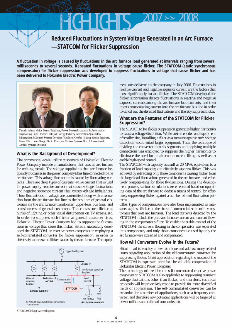
ment was delivered to the company in July 2006. Fluctuations inreactive current and negative sequence current are the factors thatmost significantly impact flicker. The STATCOM developed forflicker suppression detects fluctuations in reactive and negativesequence currents among the arc furnace load currents, and theninjects compensating current into the arc furnace bus line in orderto cancel out the detected fluctuations and thereby suppress flicker.
What are the Features of the STATCOM for FlickerSuppression?The STATCOM for flicker suppression generates higher harmonicsto cause a voltage distortion. While customers demand equipmentof smaller size, installing a filter as a measure against such voltagedistortion would entail larger equipment. Thus, the technique ofdividing the converter into six segments and applying multipleconnections was employed to suppress the higher harmonics toeliminate the need for an alternate current filter, as well as toenable high-speed control. The STATCOM with capacity as small as 20 MVA, equivalent to afraction of load capacity, can effectively suppress flicker. This wasachieved by extracting only those components causing flicker fromthe large load fluctuations generated in the arc furnace, and effec-tively compensating for those fluctuations. During the develop-ment process, various simulations were repeated based on operat-ing data of the arc furnace to devise a means of control for effec-tively suppressing flicker against a number of load fluctuation pat-terns. Other types of compensators have also been implemented as mea-sures against flicker at the sites of commercial-scale utility cus-tomers that own arc furnaces. The load currents detected by theSTATCOM include the pure arc furnace current and current flow-ing in the compensator’s filter. To enable the stable control of theSTATCOM, the current flowing in the compensator was separatedinto components, and only those components caused by only thearc furnace were extracted and compensated.
How will Converters Evolve in the Future? Hitachi had to employ a new technique and address many relatedissues regarding application of the self-commutated converter forsuppressing flicker. Great appreciation regarding the success of theSTATCOM is expressed here for the valuable cooperation ofHokuriku Electric Power Company. The technology utilized for the self-commutated reactive powercompensator STATCOM is also applicable to suppressing transientvoltage fluctuations other than flicker, and therefore, technicalproposals will be proactively made to provide for more diversifiedfields of application. The self-commutated converter can beexpanded for a number of applications, such as a frequency con-verter, and therefore new potential applications will be targeted atpower utilities and railroad companies, etc.
What is the Background of Development?The commercial-scale utility customers of Hokuriku ElectricPower Company include a manufacturer that uses an arc furnacefor melting metals. The voltage supplied to that arc furnace fre-quently fluctuates in the power company’s bus line connected to thearc furnace. This voltage fluctuation is caused by fluctuating cur-rents. There are three types of currents: active current that is usedfor power supply, reactive current that causes voltage fluctuations,and negative sequence current that causes voltage imbalances.These fluctuations in voltage are transmitted along with attenua-tion from the arc furnace bus line to the bus lines of general cus-tomers via the arc furnace transformer, upper-level bus lines, andtransformers of general customers. This causes such flicker asblinks of lighting or other visual disturbances on TV screens, etc.In order to suppress such flicker at general customer sites,Hokuriku Electric Power Company had to suppress the fluctua-tions in voltage that cause this flicker. Hitachi successfully devel-oped the STATCOM, an reactive power compensator employing aself-commutated converter for flicker suppression, in order toeffectively suppress the flicker caused by the arc furnace. The equip-
STATCOM: static synchronous compensatorTr: transformer
General customer
General customer bus line
Reduction ofΔV10–4
Upper-level system
Linkage Tr
Arc furnace customer bus line
Load current
Compensation current
STATCOM
Arc furnaceArc furnace customer
Filter
STATCOM linkage system diagram
Takashi Aihara (left), Senior Engineer, Power System Protection & AutomationEngineering Dept., Public Utility & Energy Industry Information System Div.,Information & Control Systems Division; Yasuhiro Kiyofuji (right), Senior Engineer,Power Electronics Design Dept., Electrical Control Systems Div., Information &Control Systems Division
7HITACHI TECHNOLOGY 2007–2008
Social InfrastructureBusinessSocial InfrastructureBusiness
Hitachi Advanced Construction Methodology for Nuclear PowerPlants
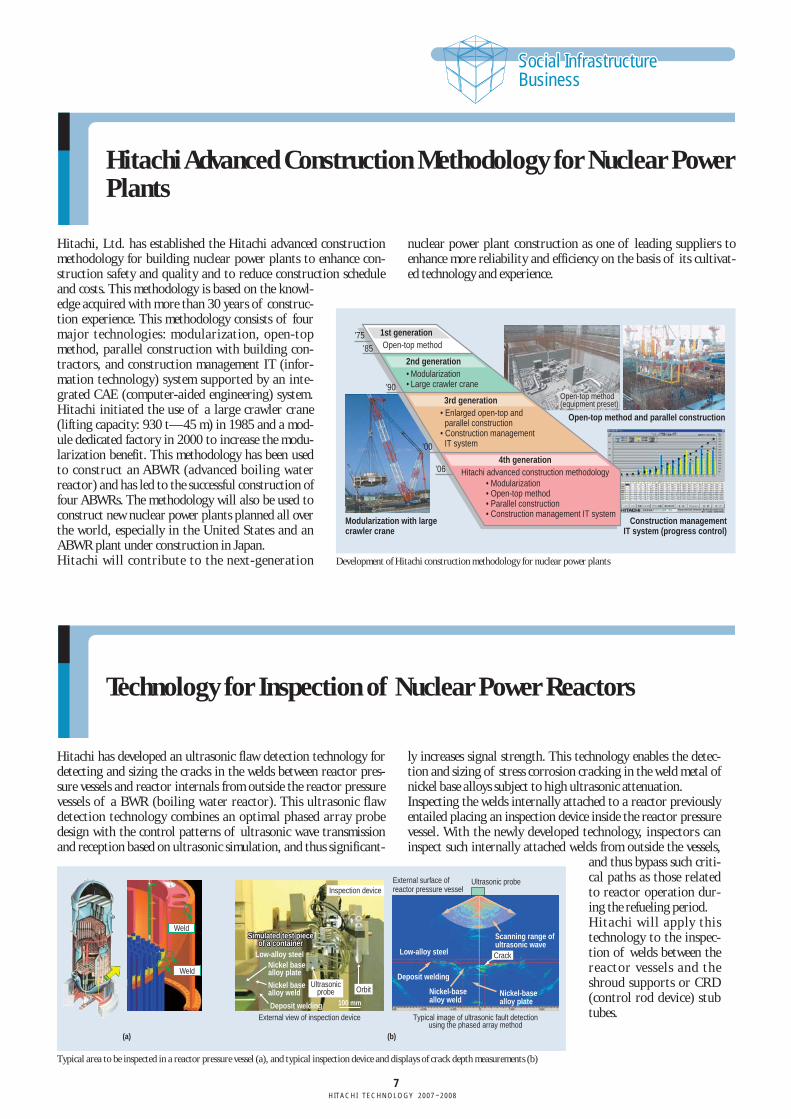
Hitachi, Ltd. has established the Hitachi advanced constructionmethodology for building nuclear power plants to enhance con-struction safety and quality and to reduce construction scheduleand costs. This methodology is based on the knowl-edge acquired with more than 30 years of construc-tion experience. This methodology consists of fourmajor technologies: modularization, open-topmethod, parallel construction with building con-tractors, and construction management IT (infor-mation technology) system supported by an inte-grated CAE (computer-aided engineering) system.Hitachi initiated the use of a large crawler crane(lifting capacity: 930 t—45 m) in 1985 and a mod-ule dedicated factory in 2000 to increase the modu-larization benefit. This methodology has been usedto construct an ABWR (advanced boiling waterreactor) and has led to the successful construction offour ABWRs. The methodology will also be used toconstruct new nuclear power plants planned all overthe world, especially in the United States and anABWR plant under construction in Japan.Hitachi will contribute to the next-generation
nuclear power plant construction as one of leading suppliers toenhance more reliability and efficiency on the basis of its cultivat-ed technology and experience.
Technology for Inspection of Nuclear Power Reactors
Hitachi has developed an ultrasonic flaw detection technology fordetecting and sizing the cracks in the welds between reactor pres-sure vessels and reactor internals from outside the reactor pressurevessels of a BWR (boiling water reactor). This ultrasonic flawdetection technology combines an optimal phased array probedesign with the control patterns of ultrasonic wave transmissionand reception based on ultrasonic simulation, and thus significant-
ly increases signal strength. This technology enables the detec-tion and sizing of stress corrosion cracking in the weld metal ofnickel base alloys subject to high ultrasonic attenuation. Inspecting the welds internally attached to a reactor previouslyentailed placing an inspection device inside the reactor pressurevessel. With the newly developed technology, inspectors caninspect such internally attached welds from outside the vessels,
and thus bypass such criti-cal paths as those relatedto reactor operation dur-ing the refueling period.Hitachi will apply thistechnology to the inspec-tion of welds between thereactor vessels and theshroud supports or CRD(control rod device) stubtubes.
(a)
External view of inspection device Typical image of ultrasonic fault detectionusing the phased array method
(b)
External surface of reactor pressure vessel
Ultrasonic probe
Weld
Weld
Inspection device
SimSimulated test pieceulated test pieceof a containerof a container
Simulated test pieceof a container
Low-alloy steel
Nickel base alloy weld
Nickel base alloy plate
Deposit welding
Orbit
Scanning range of ultrasonic wave
Deposit welding
Nickel-base alloy weld
Nickel-base alloy plate
Low-alloy steel Crack
Ultrasonicprobe
100 mm
Typical area to be inspected in a reactor pressure vessel (a), and typical inspection device and displays of crack depth measurements (b)
Modularization with large crawler crane
Construction management IT system (progress control)
Open-top method and parallel construction
1st generationOpen-top method
2nd generation• Modularization• Large crawler crane
3rd generation• Enlarged open-top and
parallel construction• Construction management
IT system
4th generationHitachi advanced construction methodology
• Modularization• Open-top method• Parallel construction• Construction management IT system
Open-top method(equipment preset)
’75’85
’90
’00
’06
Development of Hitachi construction methodology for nuclear power plants
8HITACHI TECHNOLOGY 2007–2008
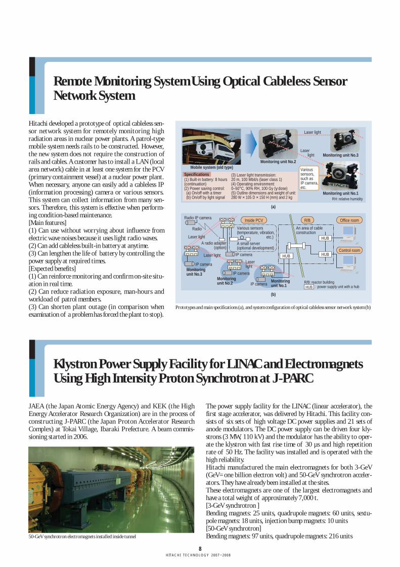
Remote Monitoring System Using Optical Cableless SensorNetwork System
Hitachi developed a prototype of optical cableless sen-sor network system for remotely monitoring highradiation areas in nuclear power plants. A patrol-typemobile system needs rails to be constructed. However,the new system does not require the construction ofrails and cables. A customer has to install a LAN (localarea network) cable in at least one system for the PCV(primary containment vessel) at a nuclear power plant.When necessary, anyone can easily add a cableless IP(information processing) camera or various sensors.This system can collect information from many sen-sors. Therefore, this system is effective when perform-ing condition-based maintenance.[Main features](1) Can use without worrying about influence fromelectric wave noises because it uses light radio waves.(2) Can add cableless built-in battery at anytime.(3) Can lengthen the life of battery by controlling thepower supply at required times.[Expected benefits](1) Can reinforce monitoring and confirm on-site situ-ation in real time.(2) Can reduce radiation exposure, man-hours andworkload of patrol members.(3) Can shorten plant outage (in comparison whenexamination of a problem has forced the plant to stop).
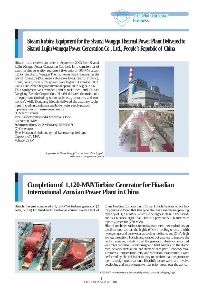
Klystron Power Supply Facility for LINAC and ElectromagnetsUsing High Intensity Proton Synchrotron at J-PARC
JAEA (the Japan Atomic Energy Agency) and KEK (the HighEnergy Accelerator Research Organization) are in the process ofconstructing J-PARC (the Japan Proton Accelerator ResearchComplex) at Tokai Village, Ibaraki Prefecture. A beam commis-sioning started in 2006.
The power supply facility for the LINAC (linear accelerator), thefirst stage accelerator, was delivered by Hitachi. This facility con-sists of six sets of high voltage DC power supplies and 21 sets ofanode modulators. The DC power supply can be driven four kly-strons (3 MW, 110 kV) and the modulator has the ability to oper-ate the klystron with fast rise time of 30 µs and high repetitionrate of 50 Hz. The facility was installed and is operated with thehigh reliability.Hitachi manufactured the main electromagnets for both 3-GeV(GeV=one billion electron volt) and 50-GeV synchrotron acceler-ators. They have already been installed at the sites.These electromagnets are one of the largest electromagnets andhave a total weight of approximately 7,000 t.[3-GeV synchrotron ]Bending magnets: 25 units, quadrupole magnets: 60 units, sextu-pole magnets: 18 units, injection bump magnets: 10 units[50-GeV synchrotron]Bending magnets: 97 units, quadrupole magnets: 216 units
R/B: reactor building
RH: relative humidity
Monitoring unit No.2Mobile system (old type)
Monitoring unit No.3
Monitoring unit No.1
HUB
HUB
Office roomInside PCV R/B
Control roomHUB
: power supply unit with a hubHUB
(a)
(b)
Specifications(1) Built-in battery: 8 hours (continuation)(2) Power saving control: (a) On/off with a timer (b) On/off by light signal
(3) Laser light transmission:20 m, 100 Mbit/s (laser class 1)(4) Operating environment:0–50°C, 90% RH, 100 Gy (γ dose)(5) Outline dimensions and weight of unit: 280 W × 105 D × 150 H (mm) and 2 kg
Radio IP camera
IP camera
IP camera
IP cameraMonitoring unit No.3
Monitoring unit No.2 Monitoring
unit No.1IP camera
Various sensors (temperature, vibration, etc.)
An area of cable construction
A small server (optional development)
Radio
Laser light
Laser light
Laser light
Various sensors, such as IP camera, etc.
Laser light
Laser light
A radio adapter (option)
50-GeV synchrotron electromagnets installed inside tunnel
Prototypes and main specifications (a), and system configuration of optical cableless sensor network system (b)
9HITACHI TECHNOLOGY 2007–2008
Social InfrastructureBusinessSocial InfrastructureBusiness
Completion of 1,120-MVA Turbine Generator for HuadianInternational Zouxian Power Plant in China
Hitachi has just completed a 1,120-MVA turbine generator (2poles, 50 Hz) for Huadian International Zouxian Power Plant of
China Huadian Corporation in China. Hitachi has carried out fac-tory tests and found that this generator has a maximum operatingcapacity of 1,230 MVA, which is the highest class in the world,and is 1.6 times larger than Hitachi’s previous 50-Hz maximumcapacity generator (778 MVA).Hitachi combined various technologies to meet the required designspecifications, such as the highly efficient cooling structure withhydrogen gas and pure water as cooling mediums, and 27-kV highvoltage insulation. Hitachi also carried out analysis to improve theperformance and reliability of the generator. Analysis performedwas rotor vibration, electromagnetic field analysis of the statorcore, network ventilation, and stress of each part. Efficiency mea-surements, temperature tests, and vibration measurements wereperformed by Hitachi in the factory to confirm that the generatormet its design specifications. Hitachi’s future work will involvedeveloping and improving power plants for use all over the world.
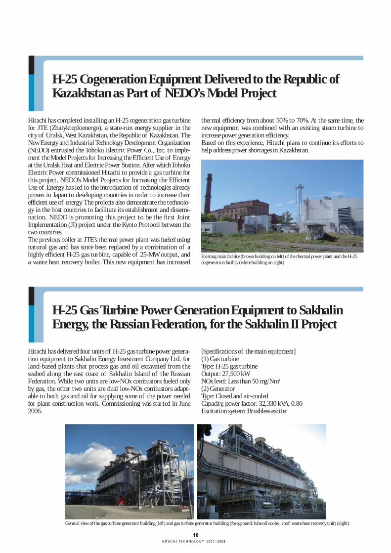
Steam Turbine Equipment for the Shanxi Wangqu Thermal Power Plant Delivered toShanxi Lujin Wangqu Power Generation Co., Ltd., People’s Republic of China
Hitachi, Ltd. received an order in September 2003 from ShanxiLujin Wangqu Power Generation Co., Ltd. for a complete set ofsteam turbine generation equipment (two units of 600-MW capac-ity) for the Shanxi Wangqu Thermal Power Plant. Located in thecity of Changzhi (950 meters above sea level), Shanxi Province,China, construction of this power plant began in December 2003.Units 1 and 2 both began commercial operation in August 2006.This equipment was awarded jointly to Hitachi and China’sDongfang Electric Corporation. Hitachi delivered the main unitsof equipment (including steam turbines, generators, and con-trollers), while Dongfang Electric delivered the auxiliary equip-ment (including condensers and boiler water supply pumps). [Specifications of the main equipment](1) Steam turbines Type: Tandem compound 4 flow exhaust type Output: 600 MWSteam conditions: 24.2 MPa (abs) -566/566 °C(2) Generators Type: Horizontal shaft and cylindrical rotating field type Capacity: 670 MVAVoltage: 22 kV
Appearance of Shanxi Wangqu Thermal Power Plant (upper), and steam turbine generator (lower)
1,120-MVA turbine generator shop test (left) and stator frame for shipping (right)
10HITACHI TECHNOLOGY 2007–2008
H-25 Cogeneration Equipment Delivered to the Republic ofKazakhstan as Part of NEDO’s Model Project
Hitachi has completed installing an H-25 cogeneration gas turbinefor JTE (Zhaiykteploenergo), a state-run energy supplier in thecity of Uralsk, West Kazakhstan, the Republic of Kazakhstan. TheNew Energy and Industrial Technology Development Organization(NEDO) entrusted the Tohoku Electric Power Co., Inc. to imple-ment the Model Projects for Increasing the Efficient Use of Energyat the Uralsk Heat and Electric Power Station. After which TohokuElectric Power commissioned Hitachi to provide a gas turbine forthis project. NEDO’s Model Projects for Increasing the EfficientUse of Energy has led to the introduction of technologies alreadyproven in Japan to developing countries in order to increase theirefficient use of energy. The projects also demonstrate the technolo-gy in the host countries to facilitate its establishment and dissemi-nation. NEDO is promoting this project to be the first JointImplementation (JI) project under the Kyoto Protocol between thetwo countries.The previous boiler at JTE’s thermal power plant was fueled usingnatural gas and has since been replaced by a combination of ahighly efficient H-25 gas turbine, capable of 25-MW output, anda waste heat recovery boiler. This new equipment has increased
thermal efficiency from about 50% to 70%. At the same time, thenew equipment was combined with an existing steam turbine toincrease power generation efficiency.Based on this experience, Hitachi plans to continue its efforts tohelp address power shortages in Kazakhstan.
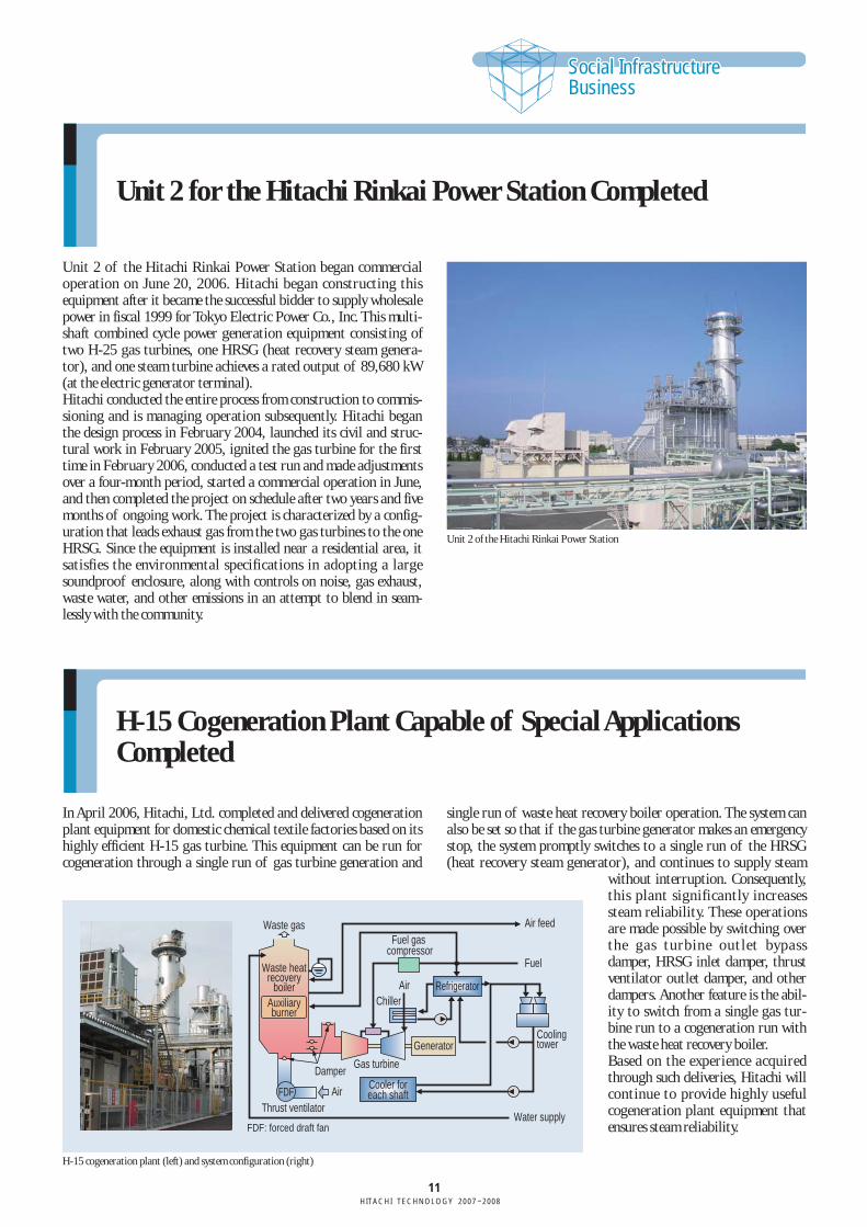
H-25 Gas Turbine Power Generation Equipment to SakhalinEnergy, the Russian Federation, for the Sakhalin II Project
Hitachi has delivered four units of H-25 gas turbine power genera-tion equipment to Sakhalin Energy Investment Company Ltd. forland-based plants that process gas and oil excavated from theseabed along the east coast of Sakhalin Island of the RussianFederation. While two units are low-NOx combustors fueled onlyby gas, the other two units are dual low-NOx combustors adapt-able to both gas and oil for supplying some of the power neededfor plant construction work. Commissioning was started in June2006.
[Specifications of the main equipment](1) Gas turbine Type: H-25 gas turbine Output: 27,500 kW NOx level: Less than 50 mg/Nm3
(2) Generator Type: Closed and air-cooled Capacity, power factor: 32,330 kVA, 0.80 Excitation system: Brushless exciter
Existing main facility (brown building on left) of the thermal power plant and the H-25cogeneration facility (white building on right)
General view of the gas turbine generator building (left) and gas turbine generator building (foreground: lube oil cooler, roof: waste heat recovery unit) (right)
11HITACHI TECHNOLOGY 2007–2008
Social InfrastructureBusinessSocial InfrastructureBusiness
Unit 2 for the Hitachi Rinkai Power Station Completed
Unit 2 of the Hitachi Rinkai Power Station began commercialoperation on June 20, 2006. Hitachi began constructing thisequipment after it became the successful bidder to supply wholesalepower in fiscal 1999 for Tokyo Electric Power Co., Inc. This multi-shaft combined cycle power generation equipment consisting oftwo H-25 gas turbines, one HRSG (heat recovery steam genera-tor), and one steam turbine achieves a rated output of 89,680 kW(at the electric generator terminal). Hitachi conducted the entire process from construction to commis-sioning and is managing operation subsequently. Hitachi beganthe design process in February 2004, launched its civil and struc-tural work in February 2005, ignited the gas turbine for the firsttime in February 2006, conducted a test run and made adjustmentsover a four-month period, started a commercial operation in June,and then completed the project on schedule after two years and fivemonths of ongoing work. The project is characterized by a config-uration that leads exhaust gas from the two gas turbines to the oneHRSG. Since the equipment is installed near a residential area, itsatisfies the environmental specifications in adopting a largesoundproof enclosure, along with controls on noise, gas exhaust,waste water, and other emissions in an attempt to blend in seam-lessly with the community.
Unit 2 of the Hitachi Rinkai Power Station
H-15 Cogeneration Plant Capable of Special ApplicationsCompleted
In April 2006, Hitachi, Ltd. completed and delivered cogenerationplant equipment for domestic chemical textile factories based on itshighly efficient H-15 gas turbine. This equipment can be run forcogeneration through a single run of gas turbine generation and
single run of waste heat recovery boiler operation. The system canalso be set so that if the gas turbine generator makes an emergencystop, the system promptly switches to a single run of the HRSG(heat recovery steam generator), and continues to supply steam
without interruption. Consequently,this plant significantly increasessteam reliability. These operationsare made possible by switching overthe gas turbine outlet bypassdamper, HRSG inlet damper, thrustventilator outlet damper, and otherdampers. Another feature is the abil-ity to switch from a single gas tur-bine run to a cogeneration run withthe waste heat recovery boiler.Based on the experience acquiredthrough such deliveries, Hitachi willcontinue to provide highly usefulcogeneration plant equipment thatensures steam reliability.
Waste gas
Waste heatrecovery
boiler
Air
Air
Water supply
Cooler foreach shaft
Damper
Auxiliaryburner
Gas turbine
Thrust ventilator
FDF: forced draft fan
FDF
Generator
Chiller
Cooling tower
Refrigerator
Fuel gas compressor
Air feed
Fuel
H-15 cogeneration plant (left) and system configuration (right)
12HITACHI TECHNOLOGY 2007–2008
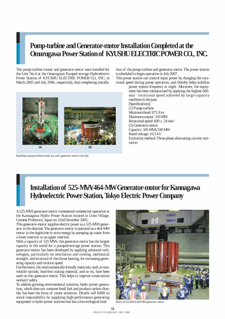
Pump-turbine and Generator-motor Installation Completed at theOmarugawa Power Station of KYUSHU ELECTRIC POWER CO., INC.
The pump-turbine runner and generator-motor were installed forthe Unit No.4 at the Omarugawa Pumped storage HydroelectricPower Station of KYUSHU ELECTRIC POWER CO., INC. inMarch 2005 and July 2006, respectively, thus completing installa-
tion of the pump-turbine and generator-motor. The power stationis scheduled to begin operation in July 2007.This power station can control input power by changing the rota-tional speed during pump operation, and thereby helps stabilize
power system frequency at night. Moreover, the equip-ment has been miniaturized by applying the highest 600-min- 1 rotational speed achieved by large-capacitymachines in the past.[Specifications](1) Pump-turbineMaximum head: 671.8 mMaximum output: 310 MWRotational speed: 600 ± 24 min-1
(2) Generator-motorCapacity: 345 MVA/330 MWRated voltage: 16.5 kVExcitation method: Three-phase alternating current exci-tation
Installing a pump-turbine runner (a), and a generator motor-rotor (b)
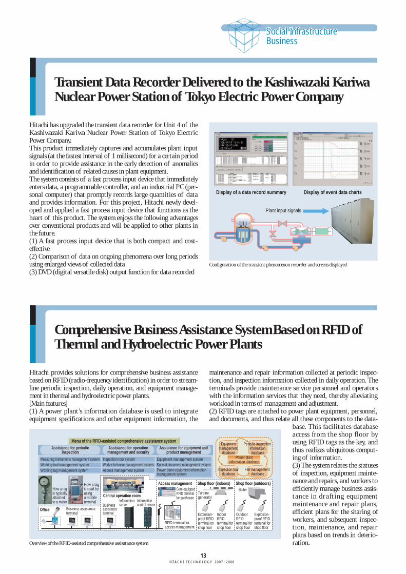
Installation of 525-MVA/464-MW Generator-motor for KannagawaHydroelectric Power Station, Tokyo Electric Power Company
A 525-MVA generator-motor commenced commercial operation atthe Kannagawa Hydro Power Station located in Ueno Village,Gumma Prefecture, Japan on 22nd December 2005.This generator-motor supplies electric power as a 525-MVA gener-ator in the daytime. The generator-motor is operated as a 464-MWmotor in the nighttime to store energy by pumping up water froma lower reservoir to an upper reservoir.With a capacity of 525 MVA, this generator-motor has the largestcapacity in the world for a pumped-storage power station. Thisgenerator-motor has been developed by applying advanced tech-nologies, particularly on ventilation and cooling, mechanicalstrength, and structure of the thrust bearing, for increasing gener-ating capacity and rotation speed. Furthermore, the environmentally-friendly materials, such as non-volatile varnish, lead-free coating material, and so on, have beenused on this generator-motor. This helps to improve constructionworkers’ safety.To address growing environmental concerns, hydro power genera-tion, which does not consume fossil fuel and produce carbon diox-ide, has been the focus of recent attention. Hitachi will fulfill itssocial responsibility by supplying high-performance generatingequipment to hydro power stations that has a low ecological load. Rotor of 525-MVA/464-MW generator-motor
(a) (b)
13HITACHI TECHNOLOGY 2007–2008
Social InfrastructureBusinessSocial InfrastructureBusiness
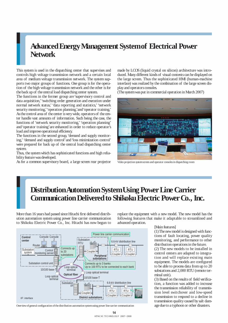
Transient Data Recorder Delivered to the Kashiwazaki KariwaNuclear Power Station of Tokyo Electric Power Company
Hitachi has upgraded the transient data recorder for Unit 4 of theKashiwazaki Kariwa Nuclear Power Station of Tokyo ElectricPower Company. This product immediately captures and accumulates plant inputsignals (at the fastest interval of 1 millisecond) for a certain periodin order to provide assistance in the early detection of anomaliesand identification of related causes in plant equipment. The system consists of a fast process input device that immediatelyenters data, a programmable controller, and an industrial PC (per-sonal computer) that promptly records large quantities of dataand provides information. For this project, Hitachi newly devel-oped and applied a fast process input device that functions as theheart of this product. The system enjoys the following advantagesover conventional products and will be applied to other plants inthe future.(1) A fast process input device that is both compact and cost-effective(2) Comparison of data on ongoing phenomena over long periodsusing enlarged views of collected data (3) DVD (digital versatile disk) output function for data recorded
Display of a data record summary Display of event data charts
Plant input signals
Configuration of the transient phenomenon recorder and screens displayed
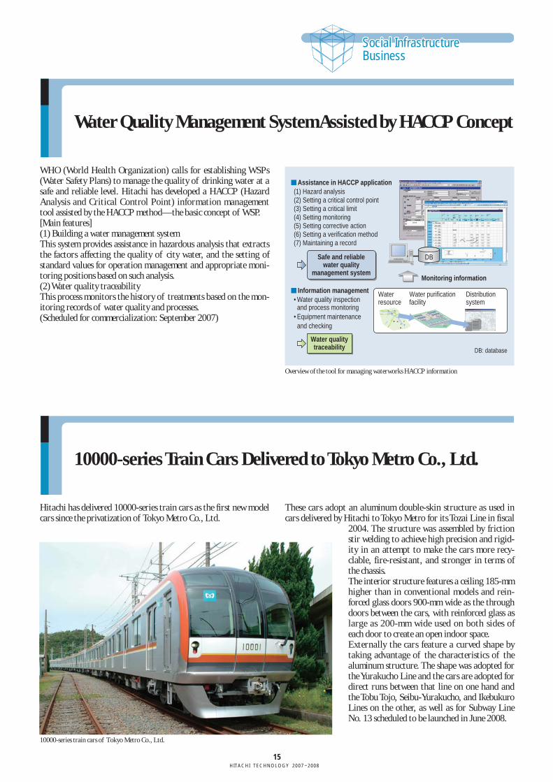
Comprehensive Business Assistance System Based on RFID ofThermal and Hydroelectric Power Plants
Hitachi provides solutions for comprehensive business assistancebased on RFID (radio-frequency identification) in order to stream-line periodic inspection, daily operation, and equipment manage-ment in thermal and hydroelectric power plants. [Main features](1) A power plant’s information database is used to integrateequipment specifications and other equipment information, the
maintenance and repair information collected at periodic inspec-tion, and inspection information collected in daily operation. Theterminals provide maintenance service personnel and operatorswith the information services that they need, thereby alleviatingworkload in terms of management and adjustment. (2) RFID tags are attached to power plant equipment, personnel,and documents, and thus relate all these components to the data-
base. This facilitates databaseaccess from the shop floor byusing RFID tags as the key, andthus realizes ubiquitous comput-ing of information.(3) The system relates the statusesof inspection, equipment mainte-nance and repairs, and workers toefficiently manage business assis-tance in drafting equipmentmaintenance and repair plans,efficient plans for the sharing ofworkers, and subsequent inspec-tion, maintenance, and repairplans based on trends in deterio-ration.
Menu of the RFID-assisted comprehensive assistance systemAssistance for periodic
inspection
Measuring instruments management systemWorking tool management systemWorking tag management system
Inspection tour systemWorker behavior management systemAccess management system
Equipment management systemSpecial document management systemPower plant equipment information management system
Assistance for operationmanagement and security
Assistance for equipment andproduct management
Equipmentmanagement
database
Periodic inspection informationdatabase
Power plantinformation database
Inspection tour database
File management database
How a tag is typically attached to a meter
How a tag is read by using a mobile terminal
Shop floor (outdoors)Shop floor (indoors)Access management
Central operation room
OfficeBusiness assistance terminal
Business assistance terminal
Gate-equipped RFID terminal for gatehouse
Information control server
Information server
Explosion-proof RFID terminal on shop floor
BoilerTurbine generator
Indoor RFID terminal for shop floor
Outdoor RFID terminal for shop floor
Explosion-proof RFID terminal for shop floor
RFID terminal for access management
Overview of the RFID-assisted comprehensive assisatance system
14HITACHI TECHNOLOGY 2007–2008
Advanced Energy Management System of Electrical PowerNetwork
This system is used in the dispatching center that supervises andcontrols high voltage transmission network and a certain localarea of medium voltage transmission network. The system sup-ports two major groups of functions. One group is for the opera-tion of the high voltage transmission network and the other is forthe back up of the central load dispatching center system.The functions in the former group are ‘supervisory control anddata acquisition,’ ‘switching order generation and execution undernormal network status,’ ‘data reporting and statistics,’ ‘networksecurity monitoring,’ ‘operation planning,’and ‘operator training.’As the control area of the center is very wide, operators of the cen-ter handle vast amounts of information. Such being the case, thefunctions of ‘network security monitoring,’ ‘operation planning’and ‘operator training’are enhanced in order to reduce operator’sload and improve operational efficiency.The functions in the second group, ‘demand and supply monitor-ing,’ ‘demand and supply control’ and ‘loss minimization control’were prepared for back up of the central load dispatching centersystem.Thus, the system which has sophisticated functions and high relia-bility feature was developed.As for a common supervisory board, a large screen rear projector
made by LCOS (liquid crystal on silicon) architecture was intro-duced. Many different kinds of visual contents can be displayed onthe large screen. Thus the sophisticated HMI (human-machineinterface) was realized by the combination of the large screen dis-play and operators consoles.(The system was put in commercial operation in March 2007)
Distribution Automation System Using Power Line CarrierCommunication Delivered to Shikoku Electric Power Co., Inc.
More than 16 years had passed since Hitachi first delivered distrib-ution automation system using power line carrier communicationto Shikoku Electric Power Co., Inc. Hitachi has now begun to
replace the equipment with a new model. The new model has thefollowing features that make it adaptable to streamlined andadvanced operation.
[Main features](1) The new model is designed with func-tions of fault locating, power qualitymonitoring, and performance to otherdistribution operations in the future. (2) The new models to be installed incontrol centers are adapted to integra-tion and will replace existing mainequipment. The models are configuredto be able to process data from up to 20substations and 2,000 RTU (remote ter-minal unit).(3) Based on the results of field verifica-tion, a function was added to increasethe transmission reliability of transmis-sion level switchover and low-speedtransmission to respond to a decline intransmission quality caused by salt dam-age due to a typhoon or other disasters.
Video projection system screen and operator consoles in dispatching room
Controlcenter
Peripheral substations
District substations
Optical fiber
6.6-kV distribution line
Connects up to 3 banksUp to 100 RTU to be connected to each bank
Connects up to 20 substations
Power line carrier communication
10/100 base-T
10/100 base-TLoop optical terminal
Loop optical terminal
Loop optical terminal
Console1
Console2
Control monitoring server
Router
Substationsystem
Substation control unit
SubstationRTU
SubstationI/F
Coupler
CouplerCoupler
RTU
Coupler
RTU
6.6-kV distribution line
Coupler
RTU
Coupler
RTU
I/F: interface
Overview of general configuration of the distribution automation system using power line carrier communication
15HITACHI TECHNOLOGY 2007–2008
Social InfrastructureBusinessSocial InfrastructureBusiness
Water Quality Management System Assisted by HACCP Concept
WHO (World Health Organization) calls for establishing WSPs(Water Safety Plans) to manage the quality of drinking water at asafe and reliable level. Hitachi has developed a HACCP (HazardAnalysis and Critical Control Point) information managementtool assisted by the HACCP method—the basic concept of WSP.[Main features](1) Building a water management systemThis system provides assistance in hazardous analysis that extractsthe factors affecting the quality of city water, and the setting ofstandard values for operation management and appropriate moni-toring positions based on such analysis.(2) Water quality traceabilityThis process monitors the history of treatments based on the mon-itoring records of water quality and processes.(Scheduled for commercialization: September 2007)
10000-series Train Cars Delivered to Tokyo Metro Co., Ltd.
Hitachi has delivered 10000-series train cars as the first new modelcars since the privatization of Tokyo Metro Co., Ltd.
These cars adopt an aluminum double-skin structure as used incars delivered by Hitachi to Tokyo Metro for its Tozai Line in fiscal
2004. The structure was assembled by frictionstir welding to achieve high precision and rigid-ity in an attempt to make the cars more recy-clable, fire-resistant, and stronger in terms ofthe chassis.The interior structure features a ceiling 185-mmhigher than in conventional models and rein-forced glass doors 900-mm wide as the throughdoors between the cars, with reinforced glass aslarge as 200-mm wide used on both sides ofeach door to create an open indoor space.Externally the cars feature a curved shape bytaking advantage of the characteristics of thealuminum structure. The shape was adopted forthe Yurakucho Line and the cars are adopted fordirect runs between that line on one hand andthe Tobu Tojo, Seibu-Yurakucho, and IkebukuroLines on the other, as well as for Subway LineNo. 13 scheduled to be launched in June 2008.
10000-series train cars of Tokyo Metro Co., Ltd.
(1) Hazard analysis (2) Setting a critical control point(3) Setting a critical limit (4) Setting monitoring (5) Setting corrective action (6) Setting a verification method (7) Maintaining a record
• Water quality inspection and process monitoring
• Equipment maintenance and checking
Assistance in HACCP application
Information management
Safe and reliablewater quality
management system
Water qualitytraceability
Monitoring information
DB: database
Water resource
Water purification facility
DB
Distribution system
Overview of the tool for managing waterworks HACCP information
16HITACHI TECHNOLOGY 2007–2008
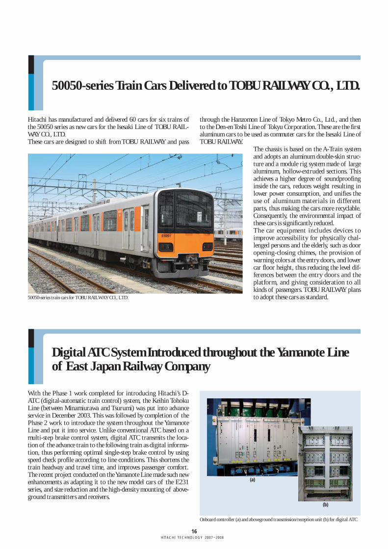
50050-series Train Cars Delivered to TOBU RAILWAY CO., LTD.
Hitachi has manufactured and delivered 60 cars for six trains ofthe 50050 series as new cars for the Isesaki Line of TOBU RAIL-WAY CO., LTD.These cars are designed to shift from TOBU RAILWAY and pass
through the Hanzomon Line of Tokyo Metro Co., Ltd., and thento the Den-en Toshi Line of Tokyu Corporation. These are the firstaluminum cars to be used as commuter cars for the Isesaki Line ofTOBU RAILWAY.
The chassis is based on the A-Train systemand adopts an aluminum double-skin struc-ture and a module rig system made of largealuminum, hollow-extruded sections. Thisachieves a higher degree of soundproofinginside the cars, reduces weight resulting inlower power consumption, and unifies theuse of aluminum materials in differentparts, thus making the cars more recyclable.Consequently, the environmental impact ofthese cars is significantly reduced.The car equipment includes devices toimprove accessibility for physically chal-lenged persons and the elderly, such as dooropening-closing chimes, the provision ofwarning colors at the entry doors, and lowercar floor height, thus reducing the level dif-ferences between the entry doors and theplatform, and giving consideration to allkinds of passengers. TOBU RAILWAY plansto adopt these cars as standard.
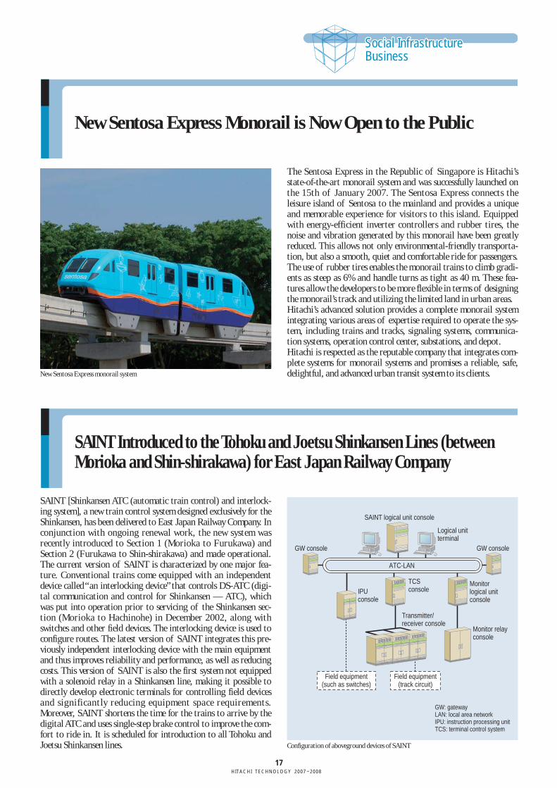
Digital ATC System Introduced throughout the Yamanote Lineof East Japan Railway Company
With the Phase 1 work completed for introducing Hitachi’s D-ATC (digital-automatic train control) system, the Keihin TohokuLine (between Minamiurawa and Tsurumi) was put into advanceservice in December 2003. This was followed by completion of thePhase 2 work to introduce the system throughout the YamanoteLine and put it into service. Unlike conventional ATC based on amulti-step brake control system, digital ATC transmits the loca-tion of the advance train to the following train as digital informa-tion, thus performing optimal single-step brake control by usingspeed check profile according to line conditions. This shortens thetrain headway and travel time, and improves passenger comfort.The recent project conducted on the Yamanote Line made such newenhancements as adapting it to the new model cars of the E231series, and size reduction and the high-density mounting of above-ground transmitters and receivers.
Onboard controller (a) and aboveground transmission/reception unit (b) for digital ATC
50050-series train cars for TOBU RAILWAY CO., LTD.
(a)
(b)
17HITACHI TECHNOLOGY 2007–2008
Social InfrastructureBusinessSocial InfrastructureBusiness
New Sentosa Express Monorail is Now Open to the Public
The Sentosa Express in the Republic of Singapore is Hitachi’sstate-of-the-art monorail system and was successfully launched onthe 15th of January 2007. The Sentosa Express connects theleisure island of Sentosa to the mainland and provides a uniqueand memorable experience for visitors to this island. Equippedwith energy-efficient inverter controllers and rubber tires, thenoise and vibration generated by this monorail have been greatlyreduced. This allows not only environmental-friendly transporta-tion, but also a smooth, quiet and comfortable ride for passengers.The use of rubber tires enables the monorail trains to climb gradi-ents as steep as 6% and handle turns as tight as 40 m. These fea-tures allow the developers to be more flexible in terms of designingthe monorail’s track and utilizing the limited land in urban areas.Hitachi’s advanced solution provides a complete monorail systemintegrating various areas of expertise required to operate the sys-tem, including trains and tracks, signaling systems, communica-tion systems, operation control center, substations, and depot.Hitachi is respected as the reputable company that integrates com-plete systems for monorail systems and promises a reliable, safe,delightful, and advanced urban transit system to its clients.New Sentosa Express monorail system
SAINT Introduced to the Tohoku and Joetsu Shinkansen Lines (betweenMorioka and Shin-shirakawa) for East Japan Railway Company
SAINT [Shinkansen ATC (automatic train control) and interlock-ing system], a new train control system designed exclusively for theShinkansen, has been delivered to East Japan Railway Company. Inconjunction with ongoing renewal work, the new system wasrecently introduced to Section 1 (Morioka to Furukawa) andSection 2 (Furukawa to Shin-shirakawa) and made operational.The current version of SAINT is characterized by one major fea-ture. Conventional trains come equipped with an independentdevice called “an interlocking device”that controls DS-ATC (digi-tal communication and control for Shinkansen — ATC), whichwas put into operation prior to servicing of the Shinkansen sec-tion (Morioka to Hachinohe) in December 2002, along withswitches and other field devices. The interlocking device is used toconfigure routes. The latest version of SAINT integrates this pre-viously independent interlocking device with the main equipmentand thus improves reliability and performance, as well as reducingcosts. This version of SAINT is also the first system not equippedwith a solenoid relay in a Shinkansen line, making it possible todirectly develop electronic terminals for controlling field devicesand significantly reducing equipment space requirements.Moreover, SAINT shortens the time for the trains to arrive by thedigital ATC and uses single-step brake control to improve the com-fort to ride in. It is scheduled for introduction to all Tohoku andJoetsu Shinkansen lines.
Logical unit terminal
Monitor logical unit console
Monitor relay console
Transmitter/receiver console
SAINT logical unit console
GW console GW console
TCS consoleIPU
console
ATC-LAN
Field equipment(such as switches)
GW: gatewayLAN: local area networkIPU: instruction processing unitTCS: terminal control system
Field equipment(track circuit)
Configuration of aboveground devices of SAINT
18HITACHI TECHNOLOGY 2007–2008
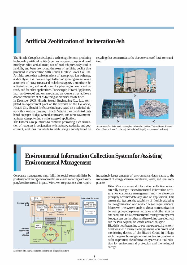
Artificial Zeolitization of Incineration Ash
The Hitachi Group has developed a technology for mass-producinghigh-quality artificial zeolite (a porous inorganic compound basedmainly on silica and alumina) out of coal ash previously used inlandfills, and been promoting the reuse of artificial zeolite thusproduced in cooperation with Chubu Electric Power Co., Inc.Artificial zeolite has stable functions of adsorption, ion exchange,and catalysis. It is therefore expected to find growing markets as anadsorbent of heavy metals and malodorous gases, a substitute foractivated carbon, soil conditioner for planting in deserts and onroofs, and for other applications. For example, Hitachi Appliances,Inc. has developed and commercialized air cleaners that achieve adeodorization rate of 99% by using an artificial zeolite filter. In December 2005, Hitachi Setsubi Engineering Co., Ltd. com-pleted an experimental plant on the premises of the Juo Works,Hitachi City, Ibaraki Prefecture in Japan, based on a technical tie-up with a venture company. Hitachi Setsubi then conducted testsbased on paper sludge, waste diatom earth, and other raw materi-als in an attempt to find a wider range of application.The Hitachi Group intends to continue promoting such circula-tion of resources in conjunction with industry, academia, and gov-ernment, and thus contribute to establishing a society based on
recycling that accommodates the characteristics of local communi-ties.
Appearance of artificial zeolitization plant delivered to Hekinan Thermal Power Plant ofChubu Electric Power Co., Inc. (a), inside the building (b), and powdered zeolite (c)
Environmental Information Collection System for AssistingEnvironmental Management
Corporate management must fulfill its social responsibilities bypositively addressing environmental issues and reducing each com-pany’s environmental impact. Moreover, corporations also require
increasingly larger amounts of environmental data relative to themanagement of energy, chemical substances, waste, and legal com-pliance.
Hitachi’s environmental information collection systemcentrally manages the environmental information neces-sary for corporate management and therefore canpromptly accommodate any kind of application. Thissystem also features the capability of flexibly adaptingto reorganization and revised legal requirements.Moreover, the system enables closer communicationbetween group companies, factories, and other sites onone hand, and EMS (environmental management system)headquarters on the other, and in so doing can effectivelyrun the PDCA (plan, do, check, and action) cycle.Hitachi is now beginning to put into perspective its com-binations with various energy-saving equipment andmonitoring devices of the Hitachi Group in linkagewith the greenhouse gas emissions trading system inorder to promote the information system as a total solu-tion for environmental protection and the saving ofenergy.
(a)
(b) (c)
SiteCSite
B
EMSheadquarters
Company-wide level
Business departments
and affiliates
Company-widepolicy
Feedback from management
Comparative study
Environmentalinformationdatabase
Once a month
GoalsPerformance
SiteA
Corporateperformance
Once a year
Information disclosure
Reports tocentral and local
governments
Environmentalreports
Response toquestionnaires
Environmental activities
ISO14001A
P
D
C
Policydetailing
Conformity ofcompany-wide
goals
Environmentalmanagement
operation
Environmentalperformance
Evolution into an environmental information integration system