bwr/pwr in-vessel inspection workshop · 2016-07-31 · bwr/pwr in-vessel inspection workshop...
TRANSCRIPT

1
BWR/PWR IN-VESSEL INSPECTION WORKSHOP
International Light Water Reactor Materials Reliability Conference and Exhibition 2016
August 1, 2016 • Hyatt Regency McCormick Place, Chicago, Illinois USA
Room 102A
AUGUST 1, 2016
TIME TOPIC PRESENTER
8:00 AM Introduction and Safety Brief Kyle Amberge (EPRI)
8:10 AM Overview of NEI 03-08, Material Initiative Chuck Wirtz (EPRI)
8:30 AM BWR Aging Management Program Development Chuck Wirtz (EPRI)
9:30 AM PWR Aging Management Program Development Kyle Amberge (EPRI)
10:30 AM Break
10:45 AM Review PWR Reactor Internals Guideline (MRP-227) Kyle Amberge (EPRI)
12:00 PM Lunch
1:00 PM Review PWR Reactor Internals Inspection Standard
(MRP-228)
Jack Spanner (EPRI)
2:30 PM Review BWR Vessel Internals (BWRVIP) Guidelines Chuck Wirtz (EPRI)
3:15 PM Break
3:30 PM Inspection Experiences, Results and Lessons Learned Jack Spanner (EPRI)
/ Jeff Landrum (EPRI)
5:00 PM Adjourn

© 2016 Electric Power Research Institute, Inc. All rights reserved.
The Materials Initiative
and
NEI 03-08
Chuck Wirtz
EPRI BWRVIP Integration Task Manager
International LWR Materials Reliability Conference
August 1, 2016

2© 2016 Electric Power Research Institute, Inc. All rights reserved.
Overview
Primary system materials integrity is vital to plant performance and reliability
Reactor components operate in a harsh environment - high temperatures, cyclic stress, vibration, intense neutron fields, etc.
Numerous materials and alloys exist in a plant’s systems and the aging of these materials is complex and not always fully understood
Routine surveillances, ISI, and replacements can mitigate some of these factors; however, some failures can be expected
Challenge: To find the next material vulnerability and to address it before any failures occur

3© 2016 Electric Power Research Institute, Inc. All rights reserved.
Operating Experience
Reactor Internals components:– Core shrouds– Core spray piping– Jet pump beams– Jet pump inlet piping– Jet pump restrainer brackets– Top guides– Steam dryers– PWR baffle bolts and split pins
Pressure boundary items:– BWR recirculation piping– BWR CRD stub tubes– Pressurizer heater sleeves– Primary system full penetration butt welds– PWR reactor vessel bottom mounted nozzles– PWR CRDM head penetrations

4© 2016 Electric Power Research Institute, Inc. All rights reserved.
Forcing Function
BWRs had programs dealing with IGSCC
– Piping covered by GL 88-01 and then BWRVIP-75
– Reactor internals managed by BWRVIP program
A series of events in PWRs motivated industry executives
to take broad generic action
– Indian Point steam generator tube
– V.C. Summer dissimilar metal weld leak
– Multiple PWR head penetration leaks
– Davis-Besse RPV head wastage

5© 2016 Electric Power Research Institute, Inc. All rights reserved.
Indian Point
February 2000:
SG tube leak
– Hidden by noise in
NDE signal

6© 2016 Electric Power Research Institute, Inc. All rights reserved.
V. C. Summer
Crack in RCS hot leg,
Fall 2000
– A Hot Leg Nozzle to
Pipe Weld
Carbon Steel Nozzle Stainless Steel Pipe
Extent of Axial Crack Extent of Circumferential Crack
Blunts at Carbon Steel

7© 2016 Electric Power Research Institute, Inc. All rights reserved.
PWR RPV Heads
Leaking PWR
CRDM Head
Penetrations

8© 2016 Electric Power Research Institute, Inc. All rights reserved.
Davis-Besse
March 2002
–CRDM
penetration
and head
wastage

9© 2016 Electric Power Research Institute, Inc. All rights reserved.
Alloy 182/600
304, 304L, or 347SS
Recirc. Inlet Safe
End and nozzle welds
Access Hole Cover
Steam Dryer
Recirc. Piping Welds
Jet Pump Riser Brace
Core Shroud Welds
Top Guide
Core Spray Piping
SRM Dry Tubes and
In-core Housing
CRD Stub Tube to
Housing Weld
Shroud-to-Shroud
Support Welds
Jet Pump Beams
Core Spray Safe End
to Nozzle Weld
Butters
Jet Pump Riser
Elbow
BWR Internal Components
10© 2016 Electric Power Research Institute, Inc. All rights reserved.
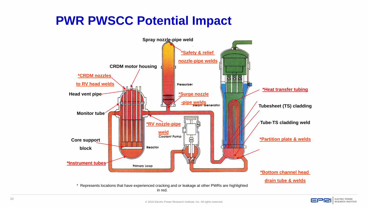
PWR PWSCC Potential Impact
*Surge nozzle
-pipe welds
Spray nozzle-pipe weld
*Safety & relief
nozzle-pipe welds
*RV nozzle-pipe
weld
CRDM motor housing
*CRDM nozzles
to RV head welds
*Instrument tubes
Core support
block
Monitor tube
Head vent pipe*Heat transfer tubing
Tubesheet (TS) cladding
Tube-TS cladding weld
*Partition plate & welds
*Bottom channel head
drain tube & welds* Represents locations that have experienced cracking and or leakage at other PWRs are highlighted
in red.

11© 2016 Electric Power Research Institute, Inc. All rights reserved.
Impact of Unexpected Operating Experience (OE)
Unanticipated Impacts – Events costly and impact reliability, safety, and performance
Davis-Besse – more than $500M
Unplanned head replacement ~ $60M to $100M and up
Unanticipated RPV penetration repairs ~$65M
Lost generation ~$1 million/day replacement power
Increased dose exposure
– Increased regulatory involvement and oversight
– Quality of life of utility work force
Something had to be done

12© 2016 Electric Power Research Institute, Inc. All rights reserved.
The issues and expectation
What will fail next?
When will it fail?
Are replacement materials susceptible?
Industry must anticipate and stay ahead of
these problems

13© 2016 Electric Power Research Institute, Inc. All rights reserved.
1st Step - Self-Assessment
In August 2002 NEI Executive Committee directed industry to:– Get in front of material issues
– Perform assessment of materials programs to identify strengths, weaknesses, and make recommendations
– Scope
Primary pressure boundary components in BWRs and PWRs
Material issues related to nuclear fuels
NDE
Chemistry/corrosion control programs
A Materials Assessment Working Group (MAWG) was formed with representatives from all industry groups dealing with materials issues

14© 2016 Electric Power Research Institute, Inc. All rights reserved.
MAWG Issue Statement
The corrosion of the base metal in the Davis-Besse reactor pressure vessel head, increased
occurrences of control rod drive mechanism nozzle cracking in pressurized water reactors
(PWRs), and the V. C. Summer hot leg dissimilar metal weld defect represent issues that have
threatened nuclear plant asset value and raised questions regarding the ability of the industry to
detect degraded conditions in reactor coolant system components and piping. Other plant events
over the last three years involving steam generator tubes, boiling water reactor (BWR) vessel
internals and other pressure boundary, vessel internals, and fuel materials suggest that the
nuclear industry has not been able to consistently anticipate and manage materials problems as
well as it could. These events also suggest the need for better integration of existing PWR and
BWR materials programs, as well as underlying technical support programs in the areas of plant
chemistry, NDE, cracking/corrosion research, etc. Lessons from programs that are working well
need to be transferred. Finally, the industry must continue to monitor and manage the impacts of
materials issues prevention and mitigation strategies on fuel reliability and performance.

15© 2016 Electric Power Research Institute, Inc. All rights reserved.
Key Conclusions from MAWG Assessment
Industry lacked a unified strategic focus and directionLimited coordination of industry efforts on materials issues Budget and funding challengesUnable to enforce and to verify implementation of industry
guidance Oversight of industry materials efforts was inconsistent Industry participation in materials issue programs lacking Implementation of materials tools inconsistent
Recommendation: Define an NSIAC Initiative to address materials aging management

16© 2016 Electric Power Research Institute, Inc. All rights reserved.
What is a NSIAC Initiative?
Formal agreement among the utility Chief Nuclear Officers (CNOs) that form the Nuclear Strategic Issues Advisory Committee (NSIAC) to follow a defined policy
Requires 80% vote of the NSIAC for approval
Binding industry commitment at CNO level for full implementation
– Not a formal regulatory commitment
– Provides regulatory credibility
– Deviation process involves an informal regulatory commitment

17© 2016 Electric Power Research Institute, Inc. All rights reserved.
Industry Materials Initiative
Unanimous NSIAC approval May 2003
Initiative provides for:– Two oversight groups for materials issues
MEOG – Materials Executive Oversight Group
MTAG – Materials Technical Advisory Group
– Proactive management of materials aging
– Integration and coordination of industry work on materials issues
– Funding provision for high priority, emergent and long term issues
– Consistent and timely implementation of guidelines
– Oversight of industry material activities
– Treated as if it were a regulatory commitment

18© 2016 Electric Power Research Institute, Inc. All rights reserved.
NEI 03-08 – Guideline for the Management of Materials
Issues
Documents the Materials Initiative
Defines scope of the Initiative
Establishes policy
Identifies Issue Programs within scope
Defines roles, and responsibilities
– MTAG and MEOG
– Issue Programs (IPs)
– Utilities
Current version is Revision 2, effective January 1, 2010
Note: Initial version of NEI 03-08 had 10 strategic elements for IPs. It recommended the BWRVIP as the program to be used as a model for 8 of the 10 elements

19© 2016 Electric Power Research Institute, Inc. All rights reserved.
Materials Initiative
The objective of this Initiative is to assure safe, reliable and efficient operation of the U.S. nuclear power
plants in the management of materials issues.
Each licensee will endorse, support and meet the intent of NEI 03-08, Guideline for the Management of
Materials Issues. This initiative is effective January 2, 2004.
The purpose of this Initiative is to:
– provide a consistent management process
– provide for prioritization of materials issues
– provide for proactive approaches
– provide for integrated and coordinated approaches to materials issues
Utility actions required by this Initiative include:
– commitment of executive leadership and technical personnel
– commitment of funds for materials issues within the scope of this Initiative
– commitment to implement applicable guidance documents
– provide for oversight of implementation

20© 2016 Electric Power Research Institute, Inc. All rights reserved.
November 2008
Materials Management Policy
Initiative Policy Statement
“… the industry will ensure that its management of materials degradation and aging is forward-looking and coordinated to the maximum extent practical. Additionally, the industry will continue to rapidly identify, react and effectively respond to emerging issues. The associated work will be managed to emphasize safety and operational risk significance as the first priority, appropriately balancing long term aging management and cost as additional considerations. To that end, as issues are identified and as work is planned, the groups involved in funding, managing and providing program oversight will ensure that the safety and operational risk significance of each issue is fully established prior to final disposition.”

21© 2016 Electric Power Research Institute, Inc. All rights reserved.
NEI 03-08 Scope and Issue Programs
Scope– Reactor internals
– Primary system pressure boundary components
– Related NDE, chemistry and corrosion controls
– Other as directed by NSIAC
Issue Programs (IPs)– EPRI
BWRVIP
MRP
SGMP
NDE
Corrosion Research (PSCR)
Chemistry Control (WCC)
– PWROG Materials Subcommittee (MSC)

22© 2016 Electric Power Research Institute, Inc. All rights reserved.
NEI 03-08 Expectations for Owners
Utility responsibilities (shall)
– Maintain a RCS Materials Degradation Management Program
– Implement “Mandatory” and “Needed” IP guidance (see next
slide)
– Participate in IPs
– Apply appropriate focus on materials issues
– Communicate materials OE

23© 2016 Electric Power Research Institute, Inc. All rights reserved.
NEI 03-08 Implementation Requirements NEI 03-08 guidance is classified as follows:
– “Mandatory” - to be implemented at all plants where applicable
– “Needed” – to be implemented whenever possible, but alternative approaches
are acceptable
– “Good Practice” – implementation is expected to provide significant operational
and reliability benefits, but the extent of use is at the discretion of the individual
plant or utility
In practice, “Mandatory” and “Needed” guidance is required unless a formal
deviation disposition is processed (similar to a ASME Code Relief Request). The
only difference for a deviation from “Mandatory” guidance versus one from
“Needed” guidance is that deviating from “Mandatory” guidance requires
independent 3rd party approval.
BWRVIP guidelines typically include an “Implementation” paragraph in Section 1 of
the report that outline the NEI 03-08 implementation requirements of the report.

24© 2016 Electric Power Research Institute, Inc. All rights reserved.
NEI 03-08 Expectations for Issue Programs
Materials IP responsibilities
– Identifying, prioritizing, and resolving issues
– Communicating
– Managing regulatory interface
– Developing guidance
– Reviewing deviations
– Self assessments and performance metrics
– Process for addressing emergent materials issues

25© 2016 Electric Power Research Institute, Inc. All rights reserved.
2008 Assessment
Industry performed an assessment of NEI 03-08
effectiveness
Key conclusions:– Overall success in achieving the Initiative’s objectives
– Broad commitment to the Policy and desired behavior is being obtained
– Overall guidance is being implemented and programs are being supported
– Continue management attention to the use of deviations
– Highest priority issues being addressed by IPs, but improvements could be obtained
by prioritizing across IP boundaries
– Roles of MEOG, MTAG, and APWGs should be revisited

26© 2016 Electric Power Research Institute, Inc. All rights reserved.
2008 Assessment Impact
MEOG and MTAG will be sunset
EPRI Materials Action Plan Committee (MAPC) to provide strategic direction for materials issues including:– EPRI materials IPs: BWRVIP, MRP, SGMP, PSCR, WCC, NDE
– PWROG MSC
NDE APC would be separate but coordinate with MAPC
BWRVIP and PWR executive committees report to MAPC for strategic coordination
MAPC members to include:– CNO as chair to coordinate with NSIAC
– Executive and Technical chairs of the IPs
– At-large members for fleet representation
– INPO and NEI representatives
Implement January 1, 2010

27© 2016 Electric Power Research Institute, Inc. All rights reserved.
Materials Organizational Structure
PMMP Executive Committee (EC)
Nuclear Power Council
Materials & Aging Action Plan Committee (MAPC)
Executive Chair:
CNO/VP Level Executive
Technical Chair:
VP/Director Level Executive
BWR Vessel Internals Program (BWRVIP)
Materials Reliability Program (MRP)
Steam Generator Mgmt Project (SGMP)
Primary System Corrosion Research
(PSCR)
BWRVIP Executive Committee
NDE Action Plan Committee*
Other APCs not shown
PWR Owners Group Materials Subcommittee (PWROG MSC)**
PMMP (EOC)
Welding & Repair Technology Center
(WRTC)
BWRVIP EOC
Water Chemistry Action Plan Committee
Long Term Operations
*NDE APC coordinates with Materials APC and PWR Owners Group **Materials Subcommittee has a representative on Materials APC
28© 2016 Electric Power Research Institute, Inc. All rights reserved.
Initiative Accomplishments
Integrated industry strategic plan for materials
Achieved a high level of industry integration, coordination, alignment, and communication on material issues
Established a process for prioritizing projects, budgets, and planning
Predictable funding for materials R&D
Engaged INPO as an active participant
Defined expectations and protocols for industry actions upon discovery of an emergent issue
Established consistent process for deviations and communication with NRC
Executive level interactions between industry and senior NRC management
Successful at closing materials issues and gaps
Fewer unexpected materials related transients

29© 2016 Electric Power Research Institute, Inc. All rights reserved.
Together…Shaping the Future of Electricity

© 2016 Electric Power Research Institute, Inc. All rights reserved.
Boiling Water Reactor
Aging Management
Program Development
Chuck Wirtz
EPRI BWRVIP Integration Task Manager
International LWR Materials Reliability Conference
August 1, 2016

2© 2016 Electric Power Research Institute, Inc. All rights reserved.
Outline
Intergranular Stress Corrosion Cracking (IGSCC) Background
and Timeline
BWROG and Industry’s Initial Response to BWR Internals
IGSCC Issues
Establishment of the BWRVIP and its Objectives
Initial Strategic Planning
Current BWRVIP Strategic Planning Processes (MDM & IMTs)
BWRVIP Organization & Membership
Summary
Regulatory Background

3© 2016 Electric Power Research Institute, Inc. All rights reserved.
Intergranular Stress Corrosion
Cracking (IGSCC)
Background and Timeline

4© 2016 Electric Power Research Institute, Inc. All rights reserved.
IGSCC Background
Shroud cracking in 1993-1994 confirmed that IGSCC of internals is a significant issue for BWRs
BWR utility executives formed the BWRVIP in mid-1994 to proactively address BWR reactor vessel and internals material condition issues
The goal was to lead industry toward proactive generic resolution of vessel and internals material condition issues with generic, cost-effective strategies
• Intergranular Stress Corrosion Cracking (IGSCC) in austenitic piping was a major issue for Boiling Water Reactors (BWRs) in the 1980s – susceptibility of reactor internals to IGSCC was also recognized

5© 2016 Electric Power Research Institute, Inc. All rights reserved.
IGSCC Background
The BWR Owners Group (BWROG) for IGSCC research formed in 1979-1980– Worked with EPRI to integrate IGSCC research for industry
– GE led much of the work to understand IGSCC
– In response to NMP-1 leaking safe-ends, EPRI developed a procedure and protocol for IGSCC UT tests
– First IGSCC ultrasonic (UT) qualification completed October 8, 1982
– NRC, EPRI and BWROG developed a 3-party agreement for the qualification of ultrasonic examiners for IGSCC
From these efforts by BWROG, EPRI and GE came:– Fundamental understanding of IGSCC
– Initial understanding of HWC
– IGSCC specific UT procedures and personnel qualification
GE devoted much to the understanding IGSCC– Ford and Andresen slip dissolution model
– Understanding fundamental cause/method of IGSCC initiation and growth allowed mitigation to be developed

6© 2016 Electric Power Research Institute, Inc. All rights reserved.
IGSCC Timeline 1965-1988
IGSCC in stainless steel piping started in early 1960s
1965 – first occurrence in commercial BWR at Dresden 1 in 6” bypass line in HAZ
1974 – Dresden 2 IGSCC detected in 4” bypass line– U.S. Atomic Energy Commission orders 15 plants to shut down and inspect 4”piping (Inspection and Enforcement Bulletins
(IEB) 74-10, 10A, 10B)
– Inspections (1974-1975) result 9 plants finding IGSCC in 4” bypass lines or 10” sch. 80 core spray pipe (IEB 75-01)
– All cracking detected to-date in small diameter and stagnant lines
1975 – newly formed NRC orders 23 BWRs shut down for inspection – operational impact
1977 – 3 international plants identify IGSCC in recirculation risers (IGSCC in high flow pipe)
1982 – Through-wall IGSCC detected by leakage at 2 safe-ends in Nine Mile Point Unit 1– Had been examined ultrasonically (UT) 9 months earlier
– Raised questions about adequacy of UT
– NRC issues IEB 82-03
1983 – NRC issues IEB 83-02 to address mounting concerns on large-bore cracking
1984 – NRC issues Generic Letter (GL) 84-07 and GL 84-11
1984, May – axial cracking detected in nozzle to safe-end weld
1984, June – BWROG approves research program to address IGSCC with NDE and Repairs
1988 – NRC issues GL 88-01 and NUREG-0313. It becomes the standard for piping exams for the next decade
7© 2016 Electric Power Research Institute, Inc. All rights reserved.
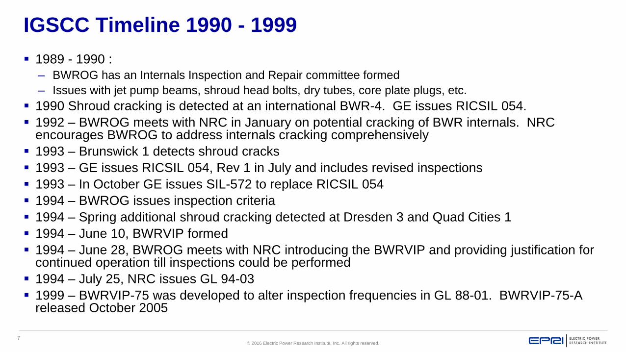
IGSCC Timeline 1990 - 1999
1989 - 1990 :
– BWROG has an Internals Inspection and Repair committee formed
– Issues with jet pump beams, shroud head bolts, dry tubes, core plate plugs, etc.
1990 Shroud cracking is detected at an international BWR-4. GE issues RICSIL 054.
1992 – BWROG meets with NRC in January on potential cracking of BWR internals. NRC encourages BWROG to address internals cracking comprehensively
1993 – Brunswick 1 detects shroud cracks
1993 – GE issues RICSIL 054, Rev 1 in July and includes revised inspections
1993 – In October GE issues SIL-572 to replace RICSIL 054
1994 – BWROG issues inspection criteria
1994 – Spring additional shroud cracking detected at Dresden 3 and Quad Cities 1
1994 – June 10, BWRVIP formed
1994 – June 28, BWROG meets with NRC introducing the BWRVIP and providing justification for continued operation till inspections could be performed
1994 – July 25, NRC issues GL 94-03
1999 – BWRVIP-75 was developed to alter inspection frequencies in GL 88-01. BWRVIP-75-A released October 2005

8© 2016 Electric Power Research Institute, Inc. All rights reserved.
Alloy 82/182, 600
304, 304L, 316 or 347SS
Recirc. Inlet and outlet Safe End and nozzle welds
Access Hole Cover
Steam Dryer
Recirc. Piping Welds
Jet Pump Riser Brace
Core Shroud Welds
Top Guide
Core Spray Piping
SRM Dry Tubes andIn-core Housing
CRD Stub Tube toHousing Weld
Shroud-to-ShroudSupport Welds
Jet Pump Beams
Core Spray Safe Endto Nozzle Weld Butters
Jet Pump Riser Elbow
Feedwater nozzle
Shroud head bolts
RPV Attachment welds
BWR Internals Susceptible to IGSCC
X-718, X-750

9© 2016 Electric Power Research Institute, Inc. All rights reserved.
Boiling Water Reactor Owners Group
(BWROG) and Industry’s Initial
Response to BWR Internals
IGSCC Issues

10© 2016 Electric Power Research Institute, Inc. All rights reserved.
GE and BWROG Addressing IGSCC in BWR Internals
GE understood possibility of IGSCC affecting reactor internals and shared the information with owners via the BWROG
GE and BWROG efforts on internals– Work by BWROG Internals Inspection and Repair committee
– Series of Service Information Letters (SILS) and Rapid Information Communication Services Information Letters (RICSILS) recommending inspections
– KKM first identified shroud cracking – 1990
– BWROG meets with NRC in January 1992 – NRC encourages action
– Brunswick 1 was the first U.S. plant to identify shroud cracking 1993
– NRC issued Information Notice (IN) 93-79
– April 1994 the BWROG produced “BWR Core Shroud Evaluation” (GE-NE-523-148-1193)
– More extensive cracking was detected at Dresden 3 and Quad Cities 1 in Spring 1994
– NRC issued IN 94-42 and IN 94-42, supplement 1 respectively

11© 2016 Electric Power Research Institute, Inc. All rights reserved.
Initial Shroud Cracking Response
NRC began questioning plant operability in light of IGSCC in shrouds and its potential to be a common mode of internals failure
Industry/BWROG and GE began work on:
– Revised shroud inspection and evaluation criteria - “BWR Shroud Cracking Safety Assessment”
– Bases for continued operation until examinations could be done
June 10, 1994 Industry executives met to discuss strategy on BWR internals cracking
– Believed effort would be too large for a committee within BWROG
– Decided to work with EPRI – effort to be similar to steam generator program
– Access to international information and not limited to NSSS vendor
– Established the BWR Vessel and Internals Project (BWRVIP)
– 7 executives volunteered to take active lead role

12© 2016 Electric Power Research Institute, Inc. All rights reserved.
Establishment of the BWRVIP
and its Objectives

13© 2016 Electric Power Research Institute, Inc. All rights reserved.
Establishment of the BWRVIP
June 28, 1994 industry executives met with NRC senior management on shroud cracking– Presented a detailed description justifying continued operation till shroud
examinations could be completed
– Introduced the BWRVIP organization to NRC – including an the executive that would lead each technical area
July 14, 1994 BWROG submitted a “BWR Shroud Cracking Safety Assessment” (GENE-523-A107P-0794)– Provided basis for continued operation presentation of June 28
– Due to urgent need, issued without BWROG member’s review
July 25, 1994 NRC Issues Generic Letter (GL) 94-03 requesting:– Owners examine their shrouds no later than next refueling outage
– Owners perform a safety assessment justifying operation till examinations are complete
– (Note: NRC later reported BWR shroud cracking to Congress as Abnormal Occurrence 94-20 in NUREG-0900, Vol. 17)

14© 2016 Electric Power Research Institute, Inc. All rights reserved.
Shroud Safety Assessment
August 5, 1994 BWROG issues Revision 1 to “BWR Shroud Cracking Safety Assessment” – Fully endorsed by owners
– Categorized plants into susceptibility groups
– Documented shroud flaw tolerance
– Evaluated the likelihood of a 360º through-wall crack in conjunction with a combination of Loss of Coolant Accident (LOCA) and seismic events
– Justified continued operation till examinations were performed
– Updated consequence analysis of 360º through-wall crack
– Appendix A documented the safety analysis including
All shroud weld locations
Normal operations and accident scenarios
Operator actions

15© 2016 Electric Power Research Institute, Inc. All rights reserved.
BWRVIP Objectives
Lead industry toward proactive generic resolution of vessel and internals material condition issues
Identify or develop generic, cost-effective strategies from which each operating plant will select the alternative most appropriate to their needs
Serve as a focal point for the regulatory interface with the industry in BWR vessel and internals material condition issues (including license renewal)
Share information among members to obtain useful data from many sources

16© 2016 Electric Power Research Institute, Inc. All rights reserved.
BWROG Transition to BWRVIP - Final Steps
September 2, 1994 BWRVIP issues BWR Core Shroud Inspection and Evaluations Guidelines (GENE-523-113-0894) to NRC (precursor to BWRVIP-01, published October 1996)
December 28, 1994 NRC issued its Safety Evaluation (SE) to the BWRVIP for the: – BWROG “BWR Core Shroud Evaluation”, and
– BWRVIP “BWR Shroud Cracking Safety Assessment”
This Safety Evaluation:– Effectively closed out the BWROG role for owners on internals cracking
completing the transition to the BWRVIP
– Identified NRC acceptance of many shroud approaches and categories
– Identified NRC concerns and limitations (NDE, reinspection, repairs, etc.)
This SE combined with the results from BWRVIP-06 set the initial course of the BWRVIP

17© 2016 Electric Power Research Institute, Inc. All rights reserved.
Initial Strategic Planning

18© 2016 Electric Power Research Institute, Inc. All rights reserved.
Initial Strategic Planning
While the initial focus of the industry efforts was to address shroud cracking, common mode failure of other internals was a concern
Parallel to the efforts to answer GL 94-03 and issue shroud safety assessments and inspection criteria a strategic planning team was formed to assess the rest of the internals
The strategic planning team included Utility, GE, Structural Integrity and EPRI members
Goal of the team– Confirm which internals were safety-related by function – support from GE systems, structural
and thermal hydraulics engineers
– For safety-related internals understand their relative significance in accident scenarios, such as:
Core spray always 1st system credited, supports long-term cooling
Jet pumps critical to maintain 2/3 core height flooded post-LOCA
– Develop a basis to prioritize work and component sequence
The result was BWRVIP-06, “Safety Assessment of BWR Reactor Internals” was published October 1995

19© 2016 Electric Power Research Institute, Inc. All rights reserved.
BWRVIP-06 Scope and Purpose
Components categorized as “safety-related” are those that can be relied upon to remain functional during and following design basis events to ensure (10CFR50.2):– (1) The integrity of the reactor coolant pressure boundary
– (2) The capability to shut down the reactor and maintain it in a safe shutdown condition; or
– (3) The capability to prevent or mitigate the consequences of accidents which could result in potential offsite exposures comparable to 10CFR100
Purpose– Perform deterministic safety assessments of all internals, penetrations and
attachments (non-safety received a less rigorous assessment)
Consider BWR/2 – BWR/6 components and subcomponents
Configurations were “as designed”, did not account for plant modifications
– Identify short and long term actions to assure safe operation assuming component cracking
– Provide a tool to assess other cracking that might occur

20© 2016 Electric Power Research Institute, Inc. All rights reserved.
BWRVIP-06 Approach
Assume each weld and/or bolted connection fully failed (synergistic or multiple component failures not considered)
Assess resulting safety consequences based on the component’s function for normal operation and accidents
Functions considered included:– Maintain coolable geometry
– Maintain rod insertion times
– Maintain reactivity control
– Assure core cooling
– Assure instrumentation availability
Assumed failures were beyond design basis in some cases
Evaluate worst case failure impact on accident consequences and plant responses considering:– Detectability of failure during operation or by inspection
– Redundancy of load carrying capability or components
– Probability of challenging event

21© 2016 Electric Power Research Institute, Inc. All rights reserved.
BWRVIP-06 Results
No short-term actions needed (premature shutdowns or other action)
Long-term actions were defined for components whose function is needed for response to:– Design basis LOCA
– Anticipated transients without scram events (ATWS)
– Seismic events
Some component failures combined with low probability events could result in increased core damage frequency
Based on relative importance to safety BWRVIP-06 provided insights on sequencing work to develop component inspection and repair guidelines for most components (e.g. fuel support casting, no action)
The results of BWRVIP-06 fed directly into the susceptibility and failure considerations contained in Section 2 of subsequent Inspection and Evaluation (I&E) guidelines for each component

22© 2016 Electric Power Research Institute, Inc. All rights reserved.
BWRVIP-09 Quantitative Safety Assessment of BWR Reactor Internals
BWRVIP-06 was a deterministic assessment
BWRVIP-06 identified eight components whose failures combined with low probability events may result in increased core damage frequency
To provide additional confidence in BWRVIP-06 and further assess impact of component failure the BWRVIP chose to perform probabilistic risk assessment (PRA) of:– Control rod guide tubes, housing and stub tubes
– Core plate
– Core spray piping
– Core spray spargers
– Jet pump assemblies
– LPCI coupling
– Access hole covers
– Top guide grid

23© 2016 Electric Power Research Institute, Inc. All rights reserved.
BWRVIP-09 Quantitative Safety Assessment of BWR Reactor Internals
Approach was to conservatively assume a conditional failure probability of 1.0 for a component
Perform PRA to calculate core damage frequency (CDF) considering LOCA and seismic events
Used conservative accident mitigating system alignments, data and modeling assumptions to obtain upper-bound CDF estimates
Compare results against a screening criteria of 1E-6 per reactor year– 1E-6 is two orders of magnitude below NRC safety target of 1E-4
If component CDF exceeded 1E-6, weld failure probabilities were assessed via Monte Carlo methods using accepted crack growth rates, fluence SCC threshold, crack distributions, etc.
Results concluded no CDF concerns, no short-term actions were needed, and supported the BWRVIPs prioritization of components for inspection and evaluation guidelines (I&EG) development
Report was submitted to NRC June 16, 1997

24© 2016 Electric Power Research Institute, Inc. All rights reserved.
BWRVIP-06 and -09, NRC response
NRC issued a Safety Evaluation Report (SER) for BWRVIP-06 and-09, dated September 15, 1998– Did not consider multiple failures on different components
– Did treat single failures conservatively in BWRVIP-06
– Did use a bounding approach to calculate CDF
– NRC research was performing an independent assessment of cascading failures
The SER concluded:– BWRVIP component prioritization was acceptable
– While multiple common mode failures were not considered, the industry had implemented effective inspection and repair programs to provide NRC high degree of confidence multiple failures would not occur and to ensure component integrity
Note: NRC’s failure assessment documented in NUREG/CR-6677 supported the BWRVIP conclusions)

25© 2016 Electric Power Research Institute, Inc. All rights reserved.
Inspection Prioritizations
Based on the results of the BWRVIP-06 and 09
Assessments, the priorities for developing BWRVIP
Inspection & Evaluation Guidelines were established as
follows:
High Priority
– Shroud
– Core Spray Piping and Sparger
– Shroud Support
– Top Guide
– Core Plate
– Standby Liquid Control System
Medium Priority
– Jet Pump Assembly
Low Priority
– Control Rod Drive Guide Tube and Stub Tubes
– Incore Housing and Dry Tubes
– Instrument Penetrations
– RPV Attachments
– Low Pressure Coolant Injection (LPCI) Coupling
26© 2016 Electric Power Research Institute, Inc. All rights reserved.
Summary of Initial Strategy
Address shroud cracking to maintain fleet safety and operability
Based off the results of BWRVIP-06 and BWRVIP-09 develop inspection and repair criteria based on prioritized list
Accelerate work on mitigation – can internals be protected and how
Develop the supporting tools needed by owners such as NDE methods, crack growth information, fluence models, etc.
Initiate long-term work to address future needs such as irradiated crack growth and fracture toughness, welding tools
Develop program structure that gave owners guidance, regulators assurance and engaged INPO
Review and adjust the program on annual basis based on OE, technical needs to support plants, regulatory needs, etc.
This was BWRVIP approach until NEI 03-08 was issued – and was effective since BWRVIP was the model for much of NEI 03-08

27© 2016 Electric Power Research Institute, Inc. All rights reserved.
Current BWRVIP Strategic
Planning Processes (MDM & IMTs)

28© 2016 Electric Power Research Institute, Inc. All rights reserved.
NEI 03-08 Integrated Materials Issues Strategic Plan
Provides systematic approach to managing materials issues
– Identify vulnerabilities
– Assess condition (inspect & evaluate)
– Mitigate degradation initiation and propagation mechanism
– Repair or replace as required
Approach used:
– Materials Degradation Matrix and Issue Management Tables
Materials Degradation Matrix and Issues Management Tables to
be maintained as living documents with annual updates

29© 2016 Electric Power Research Institute, Inc. All rights reserved.
Industry Materials Degradation and Issue Management
Table Approach
Develop a fundamental understanding of the degradation phenomena/mechanisms
Perform operability and safety assessments
Develop Inspection and evaluation guideline
Evaluate available mitigation options
Develop repair & replace options
Monitor and assess plant operation experience
Obtain regulatory acceptance
Materials Degradation Matrix (MDM) and Issue Management Tables
(IMT) are effective materials aging management tools in support of
industry’s Materials Degradation and Issue Management Initiative
MD
MIM
Ts

30© 2016 Electric Power Research Institute, Inc. All rights reserved.
The Materials Degradation Matrix (MDM)
Provides a comprehensive listing of potential degradation
mechanisms for existing LWR primary system components
Assesses the extent to which applicable degradation
mechanisms are understood
Incorporates the state of industry knowledge worldwide
associated with mitigation of applicable degradation
mechanisms
Document the results of an expert elicitation process
Proactively identifies potential challenges to avoid surprises
Is updated on periodic basis
31© 2016 Electric Power Research Institute, Inc. All rights reserved.
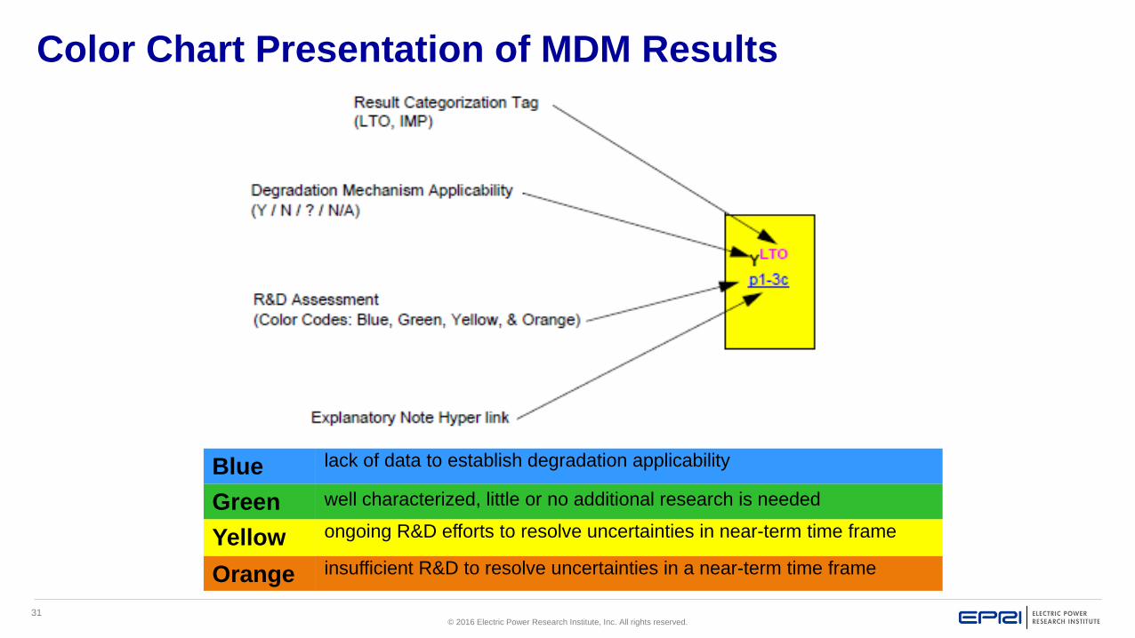
Color Chart Presentation of MDM Results
Blue lack of data to establish degradation applicability
Green well characterized, little or no additional research is needed
Yellow ongoing R&D efforts to resolve uncertainties in near-term time frame
Orange insufficient R&D to resolve uncertainties in a near-term time frame
32© 2016 Electric Power Research Institute, Inc. All rights reserved.
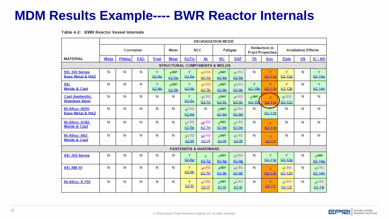
MDM Results Example---- BWR Reactor Internals

33© 2016 Electric Power Research Institute, Inc. All rights reserved.
BWR Issue Management Tables (IMTs)
BWRVIP prepares the BWR IMTs
Initially (IMT Rev 0) utilized BWRVIP-06, Safety Assessment -reflected current state of the BWRVIP Program
Identified and prioritized “gaps” by reviewing impact at a subcomponent level
Subsequent revisions included new gaps, gap revisions, gap closures, and gap prioritizations (High, Medium & Low) based on MDM updates, Operating Experience (OE), research results, and BWRVIP member input for the prioritizations
Latest version published as BWRVIP-167, Revision 3 in 2013 –includes hyperlinks to MDM gaps and EPRI document summaries

34© 2016 Electric Power Research Institute, Inc. All rights reserved.
BWR Issue Management Tables (IMTs)
Gaps are categorized as follows:
– Degradation Mechanism (DM) Understanding Gaps
– Assessment (AS) Gaps
– Mitigation (MT) Gaps
– Inspection and Evaluation (I&E) Gaps
– Repair/Replacement (RR) Gaps
– Regulatory Issue (RG) Gaps

35© 2016 Electric Power Research Institute, Inc. All rights reserved.
Example IMT – BWR Reactor Vessel Internals
Example of Gap
Description
given on next
slide

36© 2016 Electric Power Research Institute, Inc. All rights reserved.
Example Gap Description – B-AS-09

37© 2016 Electric Power Research Institute, Inc. All rights reserved.
BWRVIP Strategic Planning Process
The current IMTs are used as key input to the BWRVIP’s strategic
planning, or scope selection, process
Currently there are 47 gaps including:
– 6 Degradation Mechanism Understand gaps
– 23 Assessment gaps
– 4 Mitigation gaps
– 8 Inspection and Evaluation gaps
– 3 Repair/Replacement gaps
– 3 Regulatory Issue gaps
Of the 43 gaps, 17 are ranked High, 18 Medium, and 12 Low
Metrics established for NEI 03-08 requirements require that Issue Programs be
working on at least 90% of their High Priority gaps in order to stay “Green”

38© 2016 Electric Power Research Institute, Inc. All rights reserved.
BWRVIP Organization and Membership

39© 2016 Electric Power Research Institute, Inc. All rights reserved.
2016 BWRVIP Organization
Assessment Committee
Steve Richter, Energy Northwest (Technical Chair)
Wynter McGruder, Xcel (Vice Chair)
Denver Atwood, Southern Nuclear (RR Vice Chair)
Bob Carter, EPRI (Task Manager)
Mitigation Committee
Dan Miller, Talen Energy (Technical Chair)
David Willer, DTE (Vice Chair)
Raj Pathania, EPRI (Task Manager)
Integration Committee
Drew Odell, Exelon (Technical Chair)
Chuck Wirtz, EPRI (Task Manager)
Inspection Focus Group
Christian McKean, Exelon (Technical Chair)
Erica Mullen, DTE Energy (Vice Chair)
Jeff Landrum, EPRI (Task Manager)
Executive Committee
Tim Hanley, Exelon (Chair)
Mark Woodby, Entergy (Vice-Chair)
Andy McGehee, EPRI (Program Manager)
Executive Oversight Committee
Tim Hanley, Exelon (EC Chair)
Mark Woodby, Entergy (AC Exec Sponsor)
Bill Kopchick, PSEG (MC Exec Sponsor)
Dennis Madison, Southern (BWROG Chair)
Dave Czufin, TVA (EOC at large)
Mitigation Monitoring Focus Group
Steve Williams, Duke (Technical Chair)
Larry Loomis, Entergy (Vice Chair)
Susan Garcia, EPRI (Task Manager)

40© 2016 Electric Power Research Institute, Inc. All rights reserved.
Executive Committee
Membership consists of one executive of each BWRVIP utility member
Elects members of the Executive Oversight Committee (EOC)
Votes on proposed Charter revisions and policy issues
Meets at least once a year to review the overall direction and progress of the activities of the group
Reviews and approves the yearly BWRVIP scope, budget and funding approach
Approves all NEI 03-08 mandatory and needed guidance
Approves all reports and related transmittals that are submitted to the NRC for review and approval
41© 2016 Electric Power Research Institute, Inc. All rights reserved.
Executive Oversight Committee (EOC)
Membership consists of BWRVIP Chairman and Vice
Chairman, BWROG Chairman and two other Executive
Committee members (as Executive sponsors of the
Assessment and Mitigation Committees)
Reviews the status, direction and progress of ongoing work
Approves workscope and funding changes within the annual
budget approved by the Executive Committee
Reviews recommendations regarding emerging issues
Oversees the regulatory interface

42© 2016 Electric Power Research Institute, Inc. All rights reserved.
Assessment Committee
What needs to be inspected and at what frequency
What inspection methods – volumetric or visual
How to disposition observed degradation considering
– Examination method
– Materials
– Environment both chemical and irradiation state
Material testing to establish disposition tools such as:
– Crack growth rates
– Fracture toughness criteria
Trending and assessing inspection data

43© 2016 Electric Power Research Institute, Inc. All rights reserved.
Inspection Committee
How to inspect including
– Equipment and techniques available for each component
– Defining associated limitations and uncertainties
Maintenance of BWRVIP-03 inspection guidelines and
demonstration status
Assess visual examination reliability (Round Robin tests)
Work with vendors to develop new techniques/tools
Support new demonstrations

44© 2016 Electric Power Research Institute, Inc. All rights reserved.
Repair/Replace Committee
Define what repair/replacement techniques are available
Establish what associated requirements that must be met
Research and development on advanced welding techniques
to be used on irradiated materials
Maintain the various component Repair Design Criteria
Maintain BWRVIP-84 material selection criteria for repairs
and replacements
Assess surface mitigation techniques

45© 2016 Electric Power Research Institute, Inc. All rights reserved.
Mitigation Committee
Find the materials ultimate solution - How can SCC degradation be prevented or reduced?
Maintain BWR water chemistry guidelines
Assess fleet data and consider mitigation optimization
Assess on line NMCA deposition effectiveness
Investigate means to monitor and assure plant implementation effectiveness, e.g. Electrochemical Potential (ECP) monitoring, Noble Metals Chemical Application (NMCA) durability, etc.
Coordinate with fuels groups as mitigation options are developed/considered

46© 2016 Electric Power Research Institute, Inc. All rights reserved.
2016 BWRVIP Member Utilities
U. S.
• DTE Energy
• Duke Energy
• Energy Northwest
• Entergy
• Exelon
• FirstEnergy
• NextEra Energy
• NPPD
• PSEG Nuclear
• Southern Nuclear Company
• Talen Energy Corp
• Tennessee Valley Authority
• Xcel Energy
Intl
• BKW FMB Energie AG – Switzerland
• Chubu Electric Power Company – Japan
• Chugoku Electric Power Company – Japan
• Comision Federal de Electricidad – Mexico
• Forsmarks Kraftgrupp AB – Sweden
• Horizon - UK
• Iberdrola Generation – Spain
• JAPC – Japan
• Kernkraftwerk Leibstadt – Switzerland
• Nuclenor – Spain
• OKG Aktiebolag – Sweden
• Ringhals AB – Sweden
• Taiwan Power Company – Taiwan
• Tokyo Electric Power Company – Japan

47© 2016 Electric Power Research Institute, Inc. All rights reserved.
Summary

48© 2016 Electric Power Research Institute, Inc. All rights reserved.
Summary
IGSCC has a long and problematic history in BWRs
100’s of millions of dollar have been spent dealing with it
History shows when proper resources are brought to bear, technical issues can be resolved
When sound technical bases are developed and used, owners and regulators alike benefit and have confidence
A firm continued commitment by owners is necessary to effectively manage IGSCC and other materials degradation
– Participation in the BWRVIP both technically and financially
– Implementation of the products
– Reporting of results

49© 2016 Electric Power Research Institute, Inc. All rights reserved.
Together…Shaping the Future of Electricity

© 2016 Electric Power Research Institute, Inc. All rights reserved.
Kyle Amberge
EPRI MRP Assessment Task Manager
International LWR Materials Reliability
Conference
August 1, 2016
Pressurized Water Reactor
Internals Aging Management
Program Development

2© 2016 Electric Power Research Institute, Inc. All rights reserved.
PWR Internals Description and Function
Overview
and
MRP-227 Overview
Kyle Amberge

3© 2016 Electric Power Research Institute, Inc. All rights reserved.
PWR Internals Description and MRP-227 Overview
Topics
Aging Management Program
Nuclear Energy Institute (NEI) 03-08
−Implementation elements
MRP-227
Internals Inspection Planning
ASME Section XI Inspections
Latest Revisions to MRP-227

4© 2016 Electric Power Research Institute, Inc. All rights reserved.
Reactor Internals Aging Management Program (AMP)
Why Inspect Internals?
PWR internal components may be affected by age-related
degradation effects
As the PWR plants age, the likelihood of degradation mechanisms
occurring increases
The long-term safety & reliability of the PWR fleet requires
development & implementation of aging management strategy
The AMP supports utilities in meeting regulatory commitments for
license renewal, power uprates, and aging management of internals

5© 2016 Electric Power Research Institute, Inc. All rights reserved.
NEI 03-08, “Guideline for the Management of Materials Issues”:
Implementation Requirements
In May, 2003 the NEI Nuclear Strategic Issues Advisory Committee (NSIAC) as
a formal Industry Initiative made a commitment for each licensee to endorse,
support and meet the intent of NEI 03-08, “Guideline for the Management of
Materials Issues” in response to incidents such as VC Summer and Davis
Besse leaks
Goal is to ensure that the industry’s management of materials degradation and
aging is forward-looking, focused on issues commensurate with their safety
significance, and coordinated to the maximum extent practical. Additionally, the
industry will continue to rapidly identify, react and effectively respond to
emerging issues.
When properly implemented, this should result in fewer unanticipated issues
that consume an inordinate level of industry resources, and divert the focus from
an orderly approach to managing materials performance. It is expected that
every utility will fully participate in the implementation of the materials

6© 2016 Electric Power Research Institute, Inc. All rights reserved.
NEI 03-08 Deviation Process
NEI 03-08 Used as a Guideline (continued)
– Failure to meet a Mandatory or a Needed requirement is a ‘deviation’ from the
guidelines and a written justification for the deviation must be prepared and
approved as described in Appendix B of NEI 03-08. A copy of the deviation is
sent to the Materials Reliability Program (MRP) to evaluate if improvements
to the guidelines need to be developed and the USNRC is notified.
– MRP-227 contains Mandatory and Needed requirements to be implemented
in accordance with NEI 03-08
– MRP-228 contains Needed and Good Practice requirements to be
implemented in accordance with NEI 03-08

7© 2016 Electric Power Research Institute, Inc. All rights reserved.
MRP Reactor Internals Aging Management
Key Documents
NUREG-1801, Revision 2: Generic Aging Lessons Learned (GALL)
MRP-227: Materials Reliability Program: Pressurized Water Reactor Internals Inspection and Evaluation Guidelines
MRP-228: Materials Reliability Program: Inspection Standard for Reactor Internals
WCAP-17096-NP, Revision 2: Reactor Internals Acceptance Criteria and Data Requirements
LR-IGS-2011-04: License Renewal Interim Staff Guidance, Updated Aging Management Criteria for PWR Reactor Vessel Internal Components
MRP Letter 2014-006 ( Reactor Internals Guide Tube Wear-Westinghouse Domestic Fleet Operational Projections; WCAP-17451-P)

8© 2016 Electric Power Research Institute, Inc. All rights reserved.
PWR INTERNALS DESCRIPTION AND FUNCTION OVERVIEW
The function of PWR Internals are to:
– Provide support, guidance and protection for the reactor core;
– Provide a passageway for the distribution of the reactor coolant flow to the reactor core;
– Provide a passageway for support, guidance, and protection for control elements and in-vessel/core instrumentation; and
– Provide gamma and neutron shielding for the reactor vessel

9© 2016 Electric Power Research Institute, Inc. All rights reserved.
MRP-227 OVERVIEW
NEI-03-08 Implementation Requirements
Mandatory category requirement
Needed category requirements
MRP-227 Component Categorization
Likelihood and severity of safety
Economic consequences
Primary and Expansion
Examination method
Coverage
Examination frequency
Acceptance criteria
Primary-Expansion link

10© 2016 Electric Power Research Institute, Inc. All rights reserved.
MRP-227 GUIDELINE OVERVIEWCategorization
Aging
Management
Strategy
Development
Analysis
I& E
Guidelines
Component
List
Screening
Criteria
Initial
Screening
Cat. ANo Adverse
Effects Category B Category C
Below Screening Above Screening
No Credible
Damage Issue
HighModerate
Functionality
Analysis
Likelihood &
Severity
Analysis
Existing Expansion Primary
Resolved by
Analysis
Aging Management Program
I&E Guidelines - Rev. 0
Aging
Management
Strategy
Existing Programs New Requirements
No
Additional
Measures
Links between categorization, functionality analysis, aging management strategy development (MRP-227)
11© 2016 Electric Power Research Institute, Inc. All rights reserved.
MRP-227 Plant Specific Aging Management Programs
Implementation
Issue Resolution Classifications
– Mandatory – to be implemented at all plants where applicable
– Needed – to be implemented whenever possible but alternative
approaches are acceptable
MRP-227-Rev 1 Mandatory Element
– Each commercial U.S. PWR unit shall develop and document
and maintain an engineering program for management of aging
of reactor internal components.

12© 2016 Electric Power Research Institute, Inc. All rights reserved.
MRP-227 Plant Specific Aging Management Programs
Implementation – Needed Elements
MRP-227 Rev 1 has 4 Needed Elements
– Needed: Each commercial U.S. PWR unit shall implement the
requirements of Tables 4-1 through 4-9 and Tables 5-1 through
5-3 for the applicable design.
Implementation means performance of examinations of applicable
components within the timeframe specified in the applicable tables.

13© 2016 Electric Power Research Institute, Inc. All rights reserved.
MRP-227 Plant Specific Aging Management Programs
Implementation – Needed Elements Needed: Examinations specified in these guidelines shall comply
with the Needed requirements in the MRP-228 Inspection
Standard.
Needed: Examination results that do not meet the examination
acceptance criteria defined in Section 5 of these guidelines shall
be recorded and entered in the owner’s plant corrective action
program and dispositioned. Engineering evaluations used to
disposition an examination result that does not meet the
examination acceptance criteria in Section 5, shall be conducted
in accordance with NRC approved evaluation methods (i.e.,
ASME Code Section XI, WCAP-17096-NP or equivalent method).

14© 2016 Electric Power Research Institute, Inc. All rights reserved.
MRP-227 Plant Specific Aging Management Programs
Implementation – Needed Element(cont’d)
Needed: Each commercial U.S. PWR unit shall provide a summary
report of all inspections and monitoring (including coverage(s)
achieved and inspection limitations), items requiring evaluation, and
new repairs to the MRP Program Manager within six (6) months of
the completion of an outage during which PWR internals within the
scope of MRP-227 are examined.
• This summary of the results will be compiled into an overall
industry report and will be updated biennially
• MRP sends internals summary report to USNRC every 2 years.
15© 2016 Electric Power Research Institute, Inc. All rights reserved.
MRP-227 Development
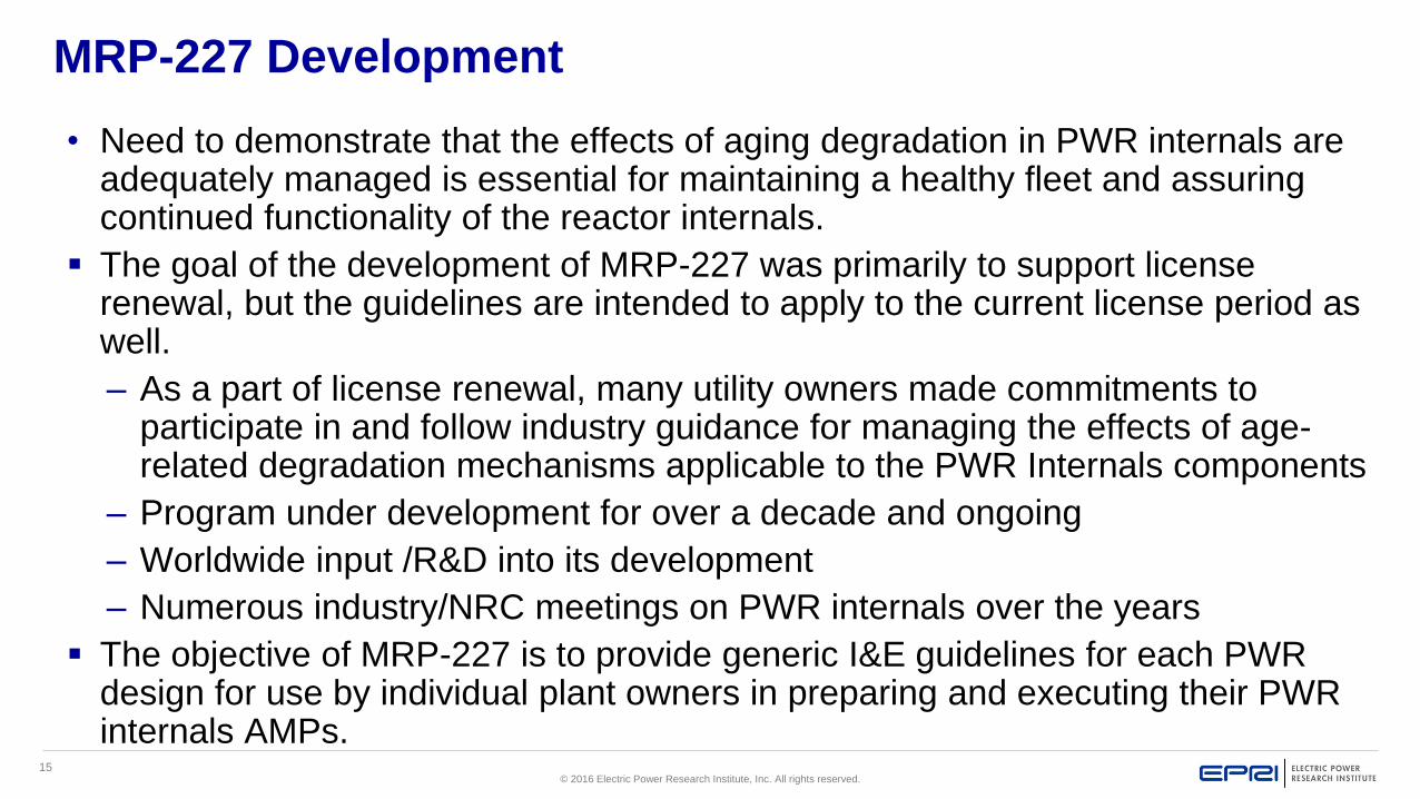
• Need to demonstrate that the effects of aging degradation in PWR internals are adequately managed is essential for maintaining a healthy fleet and assuring continued functionality of the reactor internals.
The goal of the development of MRP-227 was primarily to support license renewal, but the guidelines are intended to apply to the current license period as well.
– As a part of license renewal, many utility owners made commitments to participate in and follow industry guidance for managing the effects of age-related degradation mechanisms applicable to the PWR Internals components
– Program under development for over a decade and ongoing
– Worldwide input /R&D into its development
– Numerous industry/NRC meetings on PWR internals over the years
The objective of MRP-227 is to provide generic I&E guidelines for each PWR design for use by individual plant owners in preparing and executing their PWR internals AMPs.

16© 2016 Electric Power Research Institute, Inc. All rights reserved.
MRP-228 Rev 2 Implementation RequirementsExamination Systems Needed Elements Examinations performed according to prior versions of MRP-228 are acceptable. However, the
needed requirements of MRP-228, Rev. 2, shall be implemented for all examinations occurring 12 months after publication of this report.
– Needed: Technical Justifications are required for the examination systems specified in 2.1.1 and examination systems shall meet the qualification requirements of Section 2.1.
– Needed: All examination personnel, equipment, examinations, classification and measurement of indications, and documentation associated with visual examinations shall meet the requirements of Sections 2.3.4, 2.3.5, 2.3.6, 2.3.7, 2.3.8, and 2.3.9, respectively.
– Needed: All examination personnel, examinations, classification of indications, and documentation associated with UT shall meet the requirements of Sections 2.4.4, 2.4.6, 2.4.7, and 2.4.8, respectively.
– Needed: Personnel performing NDE methods other than visual and UT of bolting shall meet the requirements of Section 2.5.

17© 2016 Electric Power Research Institute, Inc. All rights reserved.
MRP-228 IMPLEMENTATION REQUIREMENTS (Continued)
Needed and Good Practice
Measurement Uncertainty
Needed: Technical justifications are required for determining the measurement uncertainty and shall meet the requirements of Sections 2.1.1 and 3.3.
Evaluation Factors for Measurements
Good Practice: When measuring flaw indications by visual examinations, the guidance given in Section 3 for application of evaluation factors to length measurements should be considered.
Inspection Planning
Good Practice: Planning for inspections should consider the optimum sequence and combination for inspections, such as combining visual examinations with UT of bolting in the same area of the vessel in order to minimize radiation dose to the examination personnel and reduce examination task durations (see Section 2.3).

18© 2016 Electric Power Research Institute, Inc. All rights reserved.
Industry Program OverviewDocument descriptions
Focus: Safety, Dose, Reliability
Approach: Define a proactive strategy using a systematic approach aligned with the USNRC’s generic license renewal elements for internals
MRP-227 I&E Guideline provides what and when is to be inspected
MRP-228 is an inspection standard that describes how to inspect
WCAP-17096-NP is a guideline for acceptance criteria methodology
MRP-318 gives the prioritization and contingency planning options for PWR internals
WCAP-17436 gives the results for the reactor internals risk ranking and response planning
WCAP-17451-P Revision 1 provides Control Rod Guide Tube (CRGT) guide card inspection frequencies
Note: These guidelines do not reduce, alter, or otherwise affect current American Society of Mechanical Engineers (ASME) Boiler and Pressure Vessel (B&PV) Code Section XI or plant-specific licensing inservice inspection requirements.

19© 2016 Electric Power Research Institute, Inc. All rights reserved.
ASME Section XI periodic inspections
Section XI specifies the following:– Components and items to be inspected
– Method of inspection
– Area or volume of component to be inspected
– Standards for acceptance of relevant indications
– Frequency of examinations
Inspections are required on the basis of periods and intervals– One interval is 10 years total duration
– An interval is divided into 3 periods of ~3 years each
– Inspection of some components can be deferred until end of interval, but not into the next interval

20© 2016 Electric Power Research Institute, Inc. All rights reserved.
Basis for Aging Management Program
Basic Principles
– Inspection: confirm material conditions consistent with original
functional requirements using leading component indicators
– Monitoring/Trending: based on sampling
Comply with utility’s licensing requirements
Materials Aging Assessment
– Establish thresholds for degradation mechanisms affecting internals
(EPRI technical report MRP-175)

21© 2016 Electric Power Research Institute, Inc. All rights reserved.
Relevant Aging Mechanisms and Effects
Stress Corrosion Cracking (Cracking) (SCC)
Irradiation-Assisted Stress Corrosion Cracking (Cracking) (IASCC)
Wear (Loss of Material)
Fatigue (Cracking)
Thermal Aging Embrittlement (Loss of Toughness > Cracking) (TE)
Irradiation Embrittlement (Loss of Toughness > Cracking) (IE)
Thermal and Irradiation-Enhanced Stress Relaxation (ISR) and Creep
(Loss of Preload > Wear/Cracking)
Void Swelling and Irradiation Growth (Dimensional Change or
Distortion > Cracking) (VS)

22© 2016 Electric Power Research Institute, Inc. All rights reserved.
Screening Process for MRP-227
Primary Component:
– PWR internals that are highly susceptible to the effects of at least
one of the eight aging mechanisms
– The aging management requirements provide reasonable
assurance of the continued functionality of the primary components
and predict future performance of expansion components
– Also includes components which have shown a degree of tolerance
to a specific aging degradation effect, but for which no highly
susceptible component exists or for which no highly susceptible
component is accessible
Note: Disassembly of components and assemblies not required for inspections.

23© 2016 Electric Power Research Institute, Inc. All rights reserved.
Screening Process for MRP-227
Expansion Component: PWR internals that are highly or moderately susceptible
to the effects of at least one of the eight aging mechanisms, but for which
engineering evaluations and safety assessments have shown a degree of
tolerance to those effects
Existing Programs: PWR internals that are susceptible to the effects of at least
one of the eight aging mechanisms and for which generic and plant-specific
existing AMP elements are capable of managing those effects
No Additional Measures:
– PWR internals for which effects of all eight aging mechanisms are below screening criteria
– No further action required for managing these components.

24© 2016 Electric Power Research Institute, Inc. All rights reserved.
Plant Specific Aging Management Programs
I&E Guidelines define ‘generic’ inspection strategy for the program
Plant specific program should address:
– Variations in plant design
– Plant specific operating history
– Schedule of refueling, ISI and plant modifications
– Plant specific commitments
– Demonstrate license renewal commitment alignment
Technical Basis Documents
– MRP-189 Rev 2: Screening, Categorization, and Ranking of B&W-Designed PWR Internals
– MRP-191: Screening, Categorization and Ranking of Reactor Internals of Westinghouse and CE PWR Designs
– MRP-231 Rev 3: Aging Management Strategies for B&W PWR Internals
– MRP-232 Rev 1: Aging Management Strategies for Westinghouse and Combustion Engineering PWR Internals
– WCAP-16777: Interim Report on Aging Management Strategies for Westinghouse and Combustion Engineering Reactor Vessel Internals Components
25© 2016 Electric Power Research Institute, Inc. All rights reserved.
PWR Reactor Internals Inspection Planning4-Step Engineering Program Process
1. Scope Definition
2. Development
3. Program Development and Implementation
– Pre-Inspection Engineering
– Field Inspection
4. Industry Reporting, Response, and Follow

26© 2016 Electric Power Research Institute, Inc. All rights reserved.
Step 1 and Step 2:
Engineering Program Plan
Scope Definition
– Must meet the requirements of the inspection and evaluation
guidance while considering plant-specific situations and
preferences
Development
– Couples the plant-specific scope definition with regulatory plan
requirements as defined in the ten GALL elements, MRP-227
conditions and applicant/licensee action items, and utility owner’s
plant-specific commitments and preferences.

27© 2016 Electric Power Research Institute, Inc. All rights reserved.
Aging Management Program Plan
An AMP is a tool to support effective management of critical
components as plants age
Required for License Renewal / Life Extension by GALL,
Revision 2
Only NEI 03-08 “Mandatory” Requirement in I&E Guidelines
(MRP-227)

28© 2016 Electric Power Research Institute, Inc. All rights reserved.
Aging Management Program Plan
Summary of NUREG-1801 (GALL)
Aging Management Program Elements – Scope Definition
– Preventive Actions
– Parameters to be Monitored or Inspected
– Inspection (Detection of Aging Effects)
– Monitoring or Trending
– Acceptance Criteria (Action Levels)
– Corrective Actions
– Confirmation
– Administrative Controls
– Operating Experience Review
Aging Management
Strategy Input
I&E Guidelines
(MRP-227)
Implementation

29© 2016 Electric Power Research Institute, Inc. All rights reserved.
Pre-Inspection Engineering Package
Pre-Inspection Engineering Package consists of:
– Component Inspection Details
– Acceptance Criteria
– Inspection Response Plan
Alignment with:
– MRP-227 (I&E Guideline)
– MRP-228 (Inspection Standard)
– WCAP-17096-NP Revision 2 (Acceptance Criteria)
– WCAP-17451-P ( Guide Card wear evaluation)
Nuclear safety related
Plant-specific requirements

30© 2016 Electric Power Research Institute, Inc. All rights reserved.
Component Inspection Details (CIDs)
Provide a visual reference for the location of
components to be inspected
Indicate specific area of the component to be
inspected
Show surrounding area to provide
perspective of clearances and potential
obstacles
Provide naming conventions for the
component and any observed flaws
From a MRP-227A IVI

31© 2016 Electric Power Research Institute, Inc. All rights reserved.
Acceptance Criteria
MRP-227
– Provides examination acceptance and expansion criteria
WCAP-17096-NP, Revision 2
– Provides a methodology for the analysis process
WCAP-17451-P
– Provides assessment and projection tools for guide card wear

32© 2016 Electric Power Research Institute, Inc. All rights reserved.
WCAP-17096-NP Acceptance Criteria
Philosophy
– Determine the allowable criteria (e.g., maximum crack length) that
will permit the customer to return to service for the entire inspection
cycle (typically 10 years)
– An alternate approach would be to provide acceptance criteria to
allow a return to power for 1 fuel cycle
This prevents an impact to the current outage and allows the
utility time to decide how to disposition the inspection finding

33© 2016 Electric Power Research Institute, Inc. All rights reserved.
Contingency Planning
To identify options to respond to observed material
degradation
To manage impacts on existing plant activities
Limit or bound risk of outage extension
Utility-specific risk
Bring together key stakeholders to ensure consensus

34© 2016 Electric Power Research Institute, Inc. All rights reserved.
Together…Shaping the Future of Electricity

© 2016 Electric Power Research Institute, Inc. All rights reserved.
Jack SpannerEPRI
BWR/PWR In-Vessel Inspection Workshop
EPRI International BWR & PWR MRP Conference
August 1, 2016
Chicago, IL
Review PWR Reactor Internals
Inspection Standard (MRP-
228)

2© 2016 Electric Power Research Institute, Inc. All rights reserved.
MRP-228 GUIDELINE OVERVIEW
Inspection Standard for PWR Internals
NDE System Qualification: Technical Justification Overview
Visual Examinations
– VT-1 and VT-3 use ASME Section XI requirements
– Enhanced VT-1 (EVT-1) requirements provided
Ultrasonic Examination of Bolting in Reactor Pressure Vessel Internals
– Technical Justification (TJ) based on ASME Section V, Article 14
– MRP provided protocol for future bolting demonstrations (MRP Letter 2013-011)
Nondestructive Examination (NDE) Requirements
– Personnel Training/Experience
– Equipment Requirements
– Examination Requirements
– Documentation of Results
– Measurement of Relevant Indications
– Use of MRP Mockups
NEI-03-08 Implementation Requirements

3© 2016 Electric Power Research Institute, Inc. All rights reserved.
MRP-228 General Procedures
Technical Justification Overview
Technical Justifications for NDE System Qualification
– Required for qualification of NDE systems (including measurement uncertainty) other than VT
exams
– TJ Elements
Description of the component(s) and degradation mechanism(s)
General description of the NDE system
Influential parameters and procedure essential variables
Description of the examination technique
Description of procedure experience
– Prior examinations
– Laboratory
– Demonstration tests
4© 2016 Electric Power Research Institute, Inc. All rights reserved.
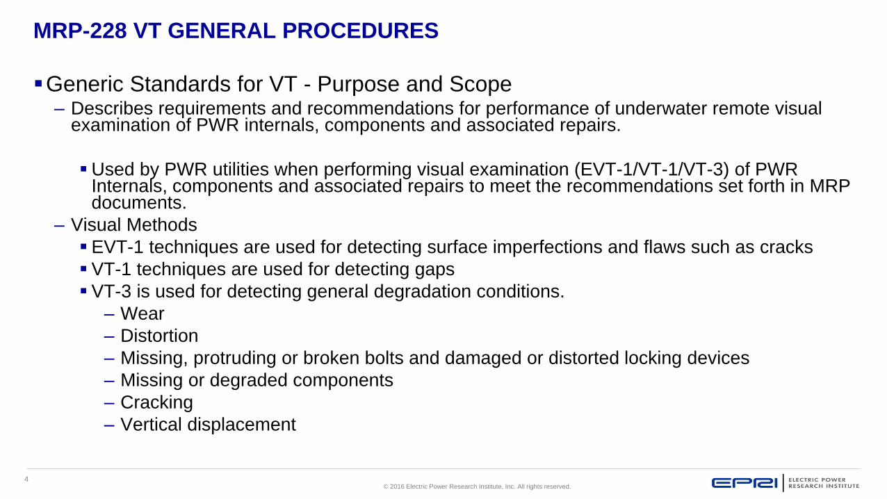
MRP-228 VT GENERAL PROCEDURES
Generic Standards for VT - Purpose and Scope– Describes requirements and recommendations for performance of underwater remote visual
examination of PWR internals, components and associated repairs.
Used by PWR utilities when performing visual examination (EVT-1/VT-1/VT-3) of PWR Internals, components and associated repairs to meet the recommendations set forth in MRP documents.
– Visual Methods
EVT-1 techniques are used for detecting surface imperfections and flaws such as cracks
VT-1 techniques are used for detecting gaps
VT-3 is used for detecting general degradation conditions.
– Wear
– Distortion
– Missing, protruding or broken bolts and damaged or distorted locking devices
– Missing or degraded components
– Cracking
– Vertical displacement

5© 2016 Electric Power Research Institute, Inc. All rights reserved.
MRP-228 USNRC Research for Remote VT
Background discussion on VT examinations– In the fall of 2004, a report titled NUREG/CR, “An Assessment of Visual Testing” was issued by
Pacific Northwest National Laboratory (PNNL) for the USNRC detailing work performed to assess the effectiveness of VT examinations as currently performed in the industry.
– The conclusions reached as a result of the work reported that as currently performed, VT examinations could not reliably detect cracks in nuclear components until a rather large Crack opening Displacement (COD) (> 40 µm; .00157 in./0.040mm)) was present.
Lighting
Speed
Pixel size versus crack opening
– Eventually, EVT-1 in the Boiling Water Reactor Vessel Inspection Program (BWRVIP) revised from a .0005 in. (0.0127mm) wire to the .044 in. (1.1mm) VT-1 characters and +/- 30º viewing angle perpendicular to the surface.

6© 2016 Electric Power Research Institute, Inc. All rights reserved.
Remote VT Round RobinConducted by USNRC and Industry
Objective of task is to assist in providing input into the specifics of performing an industry round robin for remote VT, monitoring the progress of the round robin, and assist in interpreting and reporting the round robin result.
Support USNRC Research (RES) staff in an assessment of Remote VT technology
– Implementation of a round robin
– Performed in three phases.
Determine an effective approach for performing an industry round robin designed to more accurately assess capabilities.
– Work with PNNL to design an appropriate round robin strategy.
– Provide independent reporting of round robin results.
Status
– Three phase study conducted over 5 years
Recently completed 3rd phase of testing
3rd phase included field procedures, SS cracked samples, independent analysis and relooks
EPRI report will be published in 2016

7© 2016 Electric Power Research Institute, Inc. All rights reserved.
MRP-228 EVT-1
Examination system can adequately resolve the 0.044-in. (1.1mm) characters.
Primary purpose is to find surface breaking flaws (cracking).
Surfaces to be inspected shall be sufficiently free from extraneous materials, such as crud and other deposits so that relevant conditions will not be masked. Prior to EVT-1 examination, a cleaning assessment must be performed. This applies to surfaces in the as-found condition and in the post-cleaned condition.
Camera motion should not exceed 0.5”/second (12-mm/sec).
Overlap examination scans in a manner that ensures complete coverage of the area of interest.
Camera angle should not exceed 30º to perpendicular from the examination surface or that demonstrated during Resolution Demonstration Check (RDC).
– Inspection TAC included this in MRP-228, Rev 1 2012 revision
– Obtaining coverage may be more difficult
Examination shall be performed within the distance and zoom parameters established during the RDC.

8© 2016 Electric Power Research Institute, Inc. All rights reserved.
Flaw revealed by EVT-1 technique.
The proper application of EVT-1 techniques reveals very fine details of small flaws
MRP-228
EVT-1
Fine Branching

9© 2016 Electric Power Research Institute, Inc. All rights reserved.
MRP-228
VT-1
Examination system can adequately resolve the 0.044-in. Characters.
Primary purpose is to find surface conditions such as gaps
Surfaces to be inspected shall be sufficiently free from extraneous materials, such as crud and
other deposits so that relevant conditions will not be masked.
Camera angle should not be less than 30º from the examination surface or that demonstrated
during RDC.
Examination shall be performed within the distance and zoom parameters established during the
RDC.

10© 2016 Electric Power Research Institute, Inc. All rights reserved.
MRP-228 VT Viewing Angles

11© 2016 Electric Power Research Institute, Inc. All rights reserved.
MRP-228 VT-3 Technique
VT-3
– Examination system can adequately resolve the 0.105-in. (2.7-mm) Characters.
– Looking for general mechanical and structural condition of components and to detect
discontinuities (cracking) and imperfections.
– No cleaning required.
– Camera angle should not be less than 30º from the examination surface or that demonstrated
during RDC.
– Examination shall be performed within the distance and zoom parameters established during
the RDC.

12© 2016 Electric Power Research Institute, Inc. All rights reserved.
MRP-228 Non-Relevant Indication
Scratch and discoloration
Illustration of non-relevant indication
13© 2016 Electric Power Research Institute, Inc. All rights reserved.
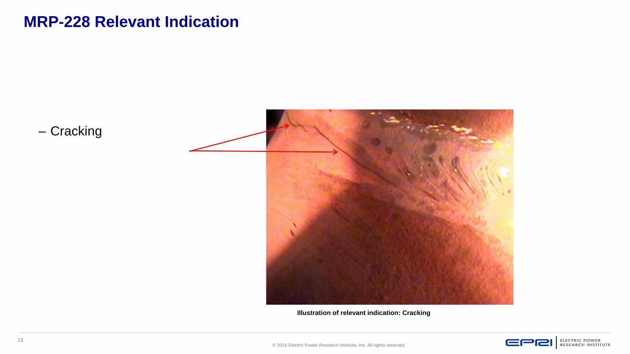
MRP-228 Relevant Indication
– Cracking
Illustration of relevant indication: Cracking

14© 2016 Electric Power Research Institute, Inc. All rights reserved.
MRP-228 VT Definitions (Continued)
Inspection Standard for VT
– Essential variable
Any element, component, or combination of the equipment used for the examination that, if changed, could affect
the ability of the examination equipment to detect indications or an evaluator’s ability to evaluate indications. The
specific essential variables will be as described in the examination procedure. These include the camera, camera
tube or board, and camera lens; video processor, monitor, and recording device (if evaluations will be performed
from recordings, i.e. resolution); and examination conditions, such as lens-to-subject distance.
– Resolution demonstration
The process of demonstrating the ability of the remote visual examination equipment, equipment setup, inspection
area environment, and examination technique to resolve the required characters on the resolution card.

15© 2016 Electric Power Research Institute, Inc. All rights reserved.
MRP-228 Resolution Card
A card bearing the characters described in Paragraphs
2.3.6.3.b.1and 2.3.6.3.b.2 of MRP-228 used to verify the adequacy
of lighting and/or remote camera resolution for EVT-1/VT-1 and VT-3
Example resolution card.

16© 2016 Electric Power Research Institute, Inc. All rights reserved.
MRP-228
VT Personnel 2.3.4
Personnel Training/Experience
– Personnel evaluating examination data shall be certified as a Level II or Level III examiner in
the VT-1 and/or VT-3 method, as appropriate, to a written practice meeting the requirements of
ASME, Section XI
– Employer training: In addition, personnel evaluating examination data shall receive a minimum
of four hours of indoctrination training on examination requirements, operation of examination
equipment, overview of MRP-228 requirements, and specific information related to the
component(s) being examined.
– Personnel evaluating examination data shall have a minimum of 10 hours of work time experience performing remote VT of internals. Experience to perform EVT-1, VT-1 or VT-3 can be accumulated separately or in combination with the other techniques.

17© 2016 Electric Power Research Institute, Inc. All rights reserved.
MRP-228
VT Personnel 2.3.4 Site-Specific Training
Utilities shall also conduct site-specific training for all personnel evaluating examination data– Topics to be included
Utility-specific procedural requirements
Configuration details
Previous examination results
Specific outage scope
Evaluation and Reporting
– Document prior to each MRP-227 examination
– MRP provides a standardized training package for utilities to provide to personnel responsible for evaluating remote visual inspection data
Materials Reliability Program: Site Specific Remote Visual Training for In-Vessel Inspections (MRP-382 Rev 1) Product ID: 3002005387

18© 2016 Electric Power Research Institute, Inc. All rights reserved.
MRP-228 VT Personnel
Personnel Training/Experience (Continued)
– Utilities shall ensure that all personnel involved in the evaluation of examination data meet the
requirements of MRP-228.
– Personnel who have had previously documented PWR internals remote visual examination
evaluation experience (which includes crack detection and characterization) are considered to
have satisfied the training and work experience requirements as described of MRP-228;
however, the items outlined in Paragraphs 2.3.4.2 a, b, and c (Review videos, non-relevant
indications and areas prone to cracking) of MRP-228 must have been included in the prior
training for those individuals or shall be included in the site-specific training specified in MRP-
228. The time required for this specific training is at the discretion of the utility.

19© 2016 Electric Power Research Institute, Inc. All rights reserved.
MRP-228 VT Equipment Requirements
2.3.5
Resolution standards for demonstrating system performance
–For purposes of demonstrating system performance, the resolution card shall include, as a minimum, the 0.044-inch characters as described in Paragraph 2.3.6.3.b.1 of MRP-228.
–An alternative resolution standard may be used if it can demonstrate sensitivity equal to or higher than that demonstrated by the 0.044-inch characters as described in Paragraph 2.3.6.3.b.1 of MRP-228.
–Where the examinations to be performed are limited to VT-3, a resolution card including VT-3 0.105-inch characters, as described in Paragraph 2.3.6.3.b.2 of MRP-228 may be used.
Underwater Cameras
–Black and white or color may be used if the entire system meets the requirements of Section 2.3.6.3 of MRP-228.
–Camera resolution and auxiliary features have significant impact on the ability to perform quality examinations and evaluate examination results.
–Resistance to radiation fields (both magnitude and duration) should be considered in the selection of camera and related equipment.

20© 2016 Electric Power Research Institute, Inc. All rights reserved.
MRP-228 Color vs. Black & White Cameras
Black & White cameras are more radiation resistant and with more
light can perform as well as color
Color cameras are affected less by motion and useful for
characterization
Examination photo taken with color camera Examination photo taken with Black&White camera

21© 2016 Electric Power Research Institute, Inc. All rights reserved.
MRP-228 GENERAL PROCEDURES
Equipment Requirements (Continued)
Cameras
– Example High Rad Underwater Cameras
Example underwater camera #2.
Example underwater camera #1.

22© 2016 Electric Power Research Institute, Inc. All rights reserved.
MRP-228 GENERAL PROCEDURES
Equipment Requirements (Continued)
Pan/Tilt/Zoom Cameras
Example Pan/Tilt/Zoom (PTZ) Underwater Cameras.

23© 2016 Electric Power Research Institute, Inc. All rights reserved.
MRP-228 GENERAL PROCEDURES
Equipment Requirements (Continued)
Cameras
– Camera lenses
Lens selection and use are at the discretion of the utility as long as the entire system meets
the demonstration requirements described in Section 2.3.6.3 of MRP-228.
Industry experience has shown that narrow angle-of-view lenses (for example, 25 mm)
produce higher levels of magnification than wide angle-of-view lenses (for example, 9 mm) at
a given camera-to-subject distance. This increases their ability to detect fine flaws at a given
distance. However, narrow angle-of-view lenses reduce the depth of field and the effective
size of the examination area, increasing the scanning and examination time.
Lenses with zoom features capable of variable magnification and depth of field may be used
if the resolution requirements of Section 2.3.6.3 of MRP-228 are met for the entire range of
the lens and examinations can be performed in a timely manner

24© 2016 Electric Power Research Institute, Inc. All rights reserved.
MRP-228 GENERAL PROCEDURES
Equipment Requirements (Continued)
Lighting
– Lighting must be controlled to avoid shadows and excessive glare. An improper angle of lighting
during examination can cast shadows into the area of interest, interfering with the ability to
detect indications. Saturating the area of interest with light can create a glare, which can also
interfere with detection of indications. When additional lighting is needed, excessive glare can
often be avoided by using a supplemental light source rather than relying on increasing the
intensity of integral camera lighting for illumination.
– Lighting sources should be equipped with a control that permits varying the intensity. The ability
to vary the degree of illumination and the angle of lighting and the use of supplemental lighting
are useful techniques for evaluating indications.
Note: Diffuse lighting is a useful technique
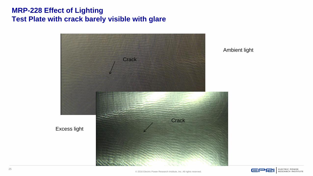
25© 2016 Electric Power Research Institute, Inc. All rights reserved.
MRP-228 Effect of Lighting
Test Plate with crack barely visible with glare
Ambient light
Excess light
Crack
Crack

26© 2016 Electric Power Research Institute, Inc. All rights reserved.
MRP-228 GENERAL PROCEDURES
Equipment Requirements (Continued)
Viewing Monitors
– Monitors used for viewing can have a direct impact on the ability to discern indications. Monitors
should have a horizontal line resolution equal to or greater than the camera to be used in the
examination.
– Although adjusting the brightness and contrast controls on the monitor can better enable
examination personnel to discern indications, adjustments to the monitor do not alter the
images being recorded. Therefore, when recording devices are being used, these controls
should be set to the neutral position. The contrast and brightness adjustments should first be
made by adjusting the lighting and camera iris. Adjustments made to the contrast and
brightness for other devices and features, such as for online image capturing or hard copy video
processors (if used), should be made subsequently. Adjusting the picture as described will help
to ensure that the recorded image will closely match that being viewed live by examination
personnel.

27© 2016 Electric Power Research Institute, Inc. All rights reserved.
MRP-228 GENERAL PROCEDURES
Equipment Requirements (Continued)
Video data recording
– Video data recording of PWR internal component inspections is not required by MRP-228, but
is recommended as a way to increase examination reliability by enabling independent data
review and the ability to compare the data with those of previous and subsequent inspections.
– When the examinations are recorded, the ability of the recording media at the settings used
during the examination should be sufficient to verify that the equipment resolution
demonstration meets the requirements described in Section 2.3.6.3 of MRP-228. This is
typically accomplished by reviewing the recorded system resolution demonstration check
performed prior to and after each examination or series of examinations.
– Where the equipment settings allow for adjusting the recording levels (for example, standard
play versus extended play), the settings for examination shall be consistent with those used for
recording the demonstration to ensure the quality of the video record.

28© 2016 Electric Power Research Institute, Inc. All rights reserved.
MRP-228 GENERAL PROCEDURES
Examination Requirements 2.3.6
Surface conditions– Surfaces to be inspected shall be free extraneous materials, such as crud and or other
deposits, so that relevant conditions will not be masked. For VT-3 examinations, the as-found condition is sufficient without further cleaning.
– Prior to EVT-1 examination (for example, to detect evidence of cracking), industry experience has shown that a cleaning assessment must be performed.
1) Surfaces shall be considered suitable for examination when surface texture identifiers such as grinding and machining marks, weld beads and ripples, undercut, and arc strikes are readily visible
2) If the suitability of a surface for examination is indeterminate, the following technique may be used: perform a pre-cleaning inspection of a worst-case area that includes the identifiers listed in 1) above; then clean the area and perform a post-cleaning inspection. If the identifiers seen in the post-cleaning inspection are significantly clearer or sharper than those in the pre-cleaning inspection or if previously undetected landmarks are identified, the existing surface conditions have the potential for masking crack indications, and cleaning shall be performed prior to inspecting.

29© 2016 Electric Power Research Institute, Inc. All rights reserved.
MRP-228 GENERAL PROCEDURES
Examination Requirements (Continued)
Surface conditions (Continued)
3) A cleaning assessment may determine that pre-inspection cleaning is needed but that it
cannot be performed due to physical restraints that prevent access for cleaning
equipment. When this is the case, a utility should perform a “Best effort” inspection of the
area and document the reason(s) that no cleaning was performed.
Note: Cleaning may momentarily decrease clarity
– Cleaning methods shall not smear surface sediment, which could mask or hinder the detection
of indications. Cleaning methods also shall not produce a polished surface finish that could
contribute to excessive glare during examination that could interfere with the detection of
indications.
– Cleaning methods must comply with site Foreign Material Exclusion (FME) requirements
– Industry experience has shown that abrasive pads can smear sediments and hinder the
detection and evaluation of indications. Nylon bristle brushes and hydro-lazing have been
shown to be effective in removing these materials without producing a shiny, reflective surface.

30© 2016 Electric Power Research Institute, Inc. All rights reserved.
MRP-228 GENERAL PROCEDURES
Color Cleaning Assessment
Surface with crud masking indicationsSurface needing cleaning for examination.
Fine detail is visible but surface crud may mask very small indications
Surface needs cleaning

31© 2016 Electric Power Research Institute, Inc. All rights reserved.
MRP-228 GENERAL PROCEDURES
Surface condition
This surface condition meets the requirements for an EVT-1
examination
Surface meeting EVT-1 cleanliness requirements.

32© 2016 Electric Power Research Institute, Inc. All rights reserved.
MRP-228 GENERAL PROCEDURES
Examination Requirements (Continued)
Environmental/Water Clarity
– Water clarity, throughout the examination, should remain equal to or better than
that used during the resolution demonstration. If water clarity becomes suspect,
examinations should be discontinued and a resolution demonstration performed
per Section 2.3.6.3 of MRP-228.
– Lighting of the examination area should be controlled using integral camera
lights and supplemental lighting as needed to maintain examination sensitivity.

33© 2016 Electric Power Research Institute, Inc. All rights reserved.
MRP-228 GENERAL PROCEDURES
Water Clarity
Water quality (Turbidity) can have a noticeable impact on
the image presented
Example of water quality impact on image quality during foreign object search

34© 2016 Electric Power Research Institute, Inc. All rights reserved.
MRP-228 GENERAL PROCEDURES
Examination Requirements (Continued)
Equipment Resolution Demonstration Requirements
– a. The resolution capabilities of the examination equipment and technique shall be
demonstrated using a resolution card (as described in Section 2.3.5.1 of MRP-228) under
environmental conditions representative of the examination area, before performing
examinations, and whenever components of the equipment that have been identified in the
procedure as essential variables are changed. Also, an RDC shall be performed at the
beginning and end of each examination or series of examinations.
– b. The RDC shall be sufficient for EVT-1 or VT-1 provided that the system is capable of
resolving the 0.044-in. characters as described in item 1. The RDC shall be sufficient for VT-3
provided that the system is capable of resolving the 0.105-in. characters. The lens-to-object
distance and zoom required to resolve the required characters becomes the maximum distance
of the lens to the surface of the item to be examined and minimum zoom that may be used
during the examination.

35© 2016 Electric Power Research Institute, Inc. All rights reserved.
MRP-228 GENERAL PROCEDURES
Examination Requirements (Continued)
Equipment Resolution Demonstration Requirements (Continued)
– 1) Remote EVT-1 or VT-1 examination processes shall be demonstrated as capable of
resolving lower case characters without ascenders or descenders (for example, a, c, e, and o)
with character heights no greater than 0.044-in. (1.1 mm) at the maximum examination distance
– 2) Remote VT-3 examination processes shall be demonstrated as capable of resolving lower
case characters without ascenders or descenders (for example, a, c, e, and o) with character
heights no greater than 0.105-in. at the maximum examination distance
– 3) Although not required, it is recommended that the RDC be recorded if examinations are to
be recorded. Whenever an RDC is recorded, a review of the video recording should be
performed prior to continuing examinations to ensure that the required characters are visible on
the recorded image.
36© 2016 Electric Power Research Institute, Inc. All rights reserved.
MRP-228 GENERAL PROCEDURES
Examination Requirements (Continued)
Equipment Resolution Demonstration Requirements (Continued)
– c. Except for the circumstances described in the next paragraph, if an RDC fails to meet the requirements previously described, all examinations performed since the last valid RDC shall be considered void and the areas reinspected.1) In cases where a camera fails (for example, electronic failure or mechanical breakage) or where degraded camera performance has been identified and the examination was video recorded, an evaluation may be performed to determine the need for re-examination. Such evaluations shall include, as a minimum, a comparison of the recorded image made immediately after the last acceptable RDC and those made just prior to the camera failure or performance degradation by a Level II (or III) remote visual examiner qualified to this standard. This review shall focus on examination landmarks to determine whether resolution just prior to the failure was equivalent to that experienced immediately after the last acceptable RDC. All such evaluations shall be independently reviewed by a Level III remote visual examiner qualified to this standard and shall be approved by the utility.

37© 2016 Electric Power Research Institute, Inc. All rights reserved.
MRP-228 GENERAL PROCEDURES
Examination Requirements (Continued)
Equipment resolution demonstration requirements (Continued)
– d. To avoid the potential for extensive re-examination, consideration should be given to performing an RDC more frequently when examinations are performed in excessively high radiation fields.
– It has been observed that cameras may burn out in high radiation fields. In black-and-white cameras, this is indicated by foggy or hazy areas or spots on the monitor; for color cameras, white spots, “snowy” images, or complete white-out may occur. This condition can be temporary or permanent. If it occurs, the camera should be moved to a lower radiation field and an RDC performed. If the required characters on the resolution card can be resolved, the camera may continue to be used; however, consideration should be given to using a more radiation-tolerant camera in the area that produced the condition. If, however, the required characters cannot be resolved, the camera shall be repaired or replaced, and all areas inspected since the last acceptable RDC shall be reinspected except as noted in item c.

38© 2016 Electric Power Research Institute, Inc. All rights reserved.
MRP-228 GENERAL PROCEDURES
Examination Requirements (Continued)
Area(s) of interest
– For EVT-1 or VT-1 examination of components, the area of interest shall consist of all accessible
surfaces of the component. For welds, the area of interest is generally considered the entire width of
the weld and ¾ in. (19-mm) of the adjacent base material on each side of the weld. However, for
small welds such as the control rod guide tube upper flange welds, the entire weld and 0.25 in. (6
mm) of the adjacent base material is the area of interest. To determine the adequacy of coverage,
the area of interest may be further refined based on the damage mechanism for the items identified
in MRP-227. Such refined determinations of coverage adequacy shall be documented in the
inspection report, as prepared or reviewed by a Level III remote visual examiner qualified to this
standard, and shall be approved by the utility.
– For VT-3 examinations, specific coverage determinations are not required. The VT-3 consists of a
general condition examination of the accessible portions of the item, and the area of interest is
dependent on the damage mechanisms for the item as identified in the applicable examination
requirement of MRP-227.

39© 2016 Electric Power Research Institute, Inc. All rights reserved.
Air Bubbles on Lenses

40© 2016 Electric Power Research Institute, Inc. All rights reserved.
Air Bubbles on Lenses Causing System to Focus on Bubbles
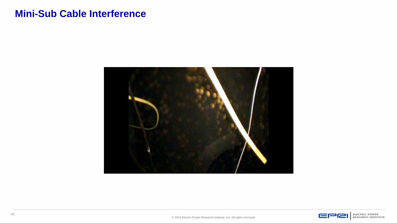
41© 2016 Electric Power Research Institute, Inc. All rights reserved.
Mini-Sub Cable Interference

42© 2016 Electric Power Research Institute, Inc. All rights reserved.
Resolving False Indications
42
During VT-3 examination of the control rod guide tube (CRGT) spacer
castings, potential crack-like indications were seen in the C-tubes at the
intersection of the C-tube and spacer castings. These locations were not part
of the MRP-227A reactor internals inspection scope (they were adjacent to
the examination area).
Deployed a different (higher resolution, closer & better angle to area of
concern) camera to obtain a better view of the anomalies.
The video obtained by the supplemental camera of the area of interest
revealed no suspect conditions. The previously identified questionable areas
were considered acceptable.
Original Camera High Res Camera

43© 2016 Electric Power Research Institute, Inc. All rights reserved.
Radiation Effects
Black & White camera Example of foggy or hazy image due to
high radiation field
Color camera Example of snowy image due to high radiation field
(will be discussed later in the course)

44© 2016 Electric Power Research Institute, Inc. All rights reserved.
Camera Effects of High Radiation Fields

45© 2016 Electric Power Research Institute, Inc. All rights reserved.
Camera Effects of High Radiation Fields

46© 2016 Electric Power Research Institute, Inc. All rights reserved.
MRP-228 GENERAL PROCEDURES
Summary
Examination Technique
1. Maximum and proper examination distance and zoom
2. Use audio commentary to describe the component, examination and findings
3. Character generators are also useful
4. Avoid shadows in the area of interest
5. Camera speed should not exceed 0.5 in/sec (EVT-1).
6. Overlap to ensure complete coverage
7. To the extent permitted by accessibility and component geometry, the camera should be
positioned such that the angle view is not more than 30 degrees from perpendicular to the
surface of the item being inspected for EVT-1. Larger angles may be used if demonstrated
during the RDC.

47© 2016 Electric Power Research Institute, Inc. All rights reserved.
MRP-228 GENERAL PROCEDURES
Examination Requirements (Continued)
Inspection planning
– In order to optimize inspection time, consideration should be given to organizing the
examinations to be performed in specific areas of the vessel coincidentally, such as performing
a VT-3 of the locking devices while performing the ultrasonic examination of the associated bolt.
– Good inspection planning will also:
Reduce dose to personnel
Reduce dose to equipment
Allow for inspecting most likely to fail items first
Ensure that examinations will not interfere with other activities
Consider reactor and component configurations which facilitate proper examination conditions

48© 2016 Electric Power Research Institute, Inc. All rights reserved.
MRP-228 GENERAL PROCEDURES
Classification
Examination Requirements (Continued)
– Classification of indications
Indications and conditions shall be classified as either relevant or non-relevant.
Initial interpretation and evaluation of indications should be performed during the examination (real time).
Processes such as digital image enhancement may be used for evaluation provided that they produce the required resolution sensitivity.
Review of recorded evaluations is recommended. Industry experience has shown that an independent review of the examination, performed by a second qualified individual, significantly increases the level of confidence that indications and conditions have been properly identified and evaluated. Recording of the examination provides a way for this review to be accomplished separate from the critical path.

49© 2016 Electric Power Research Institute, Inc. All rights reserved.
MRP-228 GENERAL PROCEDURES
Sizing
Examination Requirements (Continued)
– Measurement of relevant Indications
Determining indication length (that is, linear indications) on vessel internal components can be challenging if remote
operation of measuring tools is necessary. However, rulers and specially made or improved measuring tools and
techniques have been used to measure indication lengths with acceptable accuracy and repeatability.
Where known measurement accuracy is needed to support condition assessment of components within the scope of
the Guidelines (MRP-227), measurements may be taken by any technique, provided that it can be shown to have a
repeatable accuracy under the conditions in which it will be used.
There are various types of software and hardware available that use pixel count, laser grid patterns, image
comparison or other techniques to give highly accurate measurements.
Note: Length measurements may be difficult because crack opening displacement (COD) may vary along length of
crack, particularly at ends
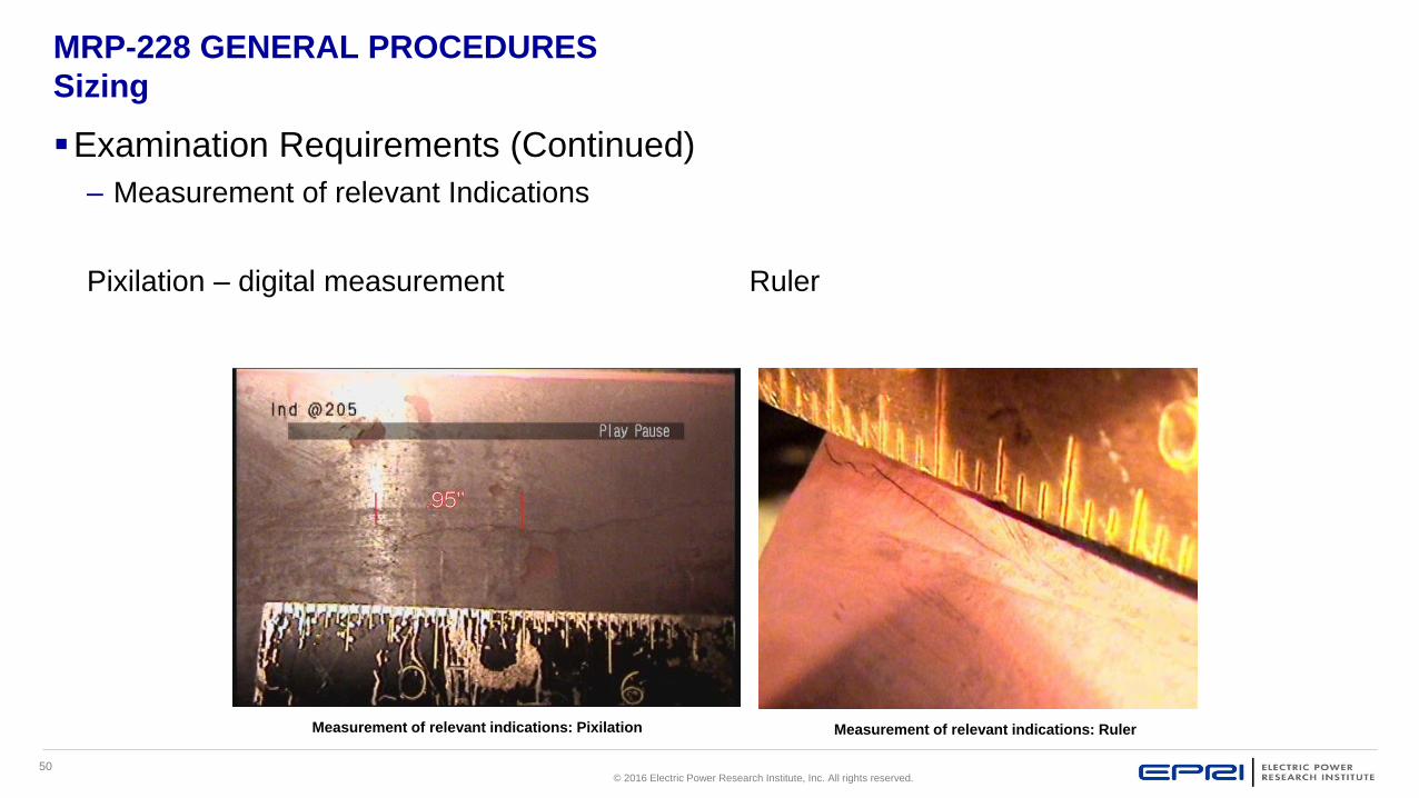
50© 2016 Electric Power Research Institute, Inc. All rights reserved.
MRP-228 GENERAL PROCEDURES
Sizing
Examination Requirements (Continued)
– Measurement of relevant Indications
Pixilation – digital measurement Ruler
Measurement of relevant indications: Pixilation Measurement of relevant indications: Ruler

51© 2016 Electric Power Research Institute, Inc. All rights reserved.
MRP-228 GENERAL PROCEDURES
Flaw length
Flaw Length Measurement by Visual Examination
– Background
Although MRP-228 does not restrict the flaw measurement techniques that may be used
Techniques not using rulers or landmarks must be supported by the Technical Justification for the
NDE system
Previous studies by other industry programs and the NRC have identified the limitations of remote
visual examination systems used for underwater visual examinations, including flaw length sizing.
– Techniques
Two techniques have generally been used for flaw length measurement during remote visual
examinations: direct measurement with a ruler or comparison of flaw indications with adjacent items or
features of known dimensions. Variations on these techniques can be used to improve their accuracy
and repeatability.

52© 2016 Electric Power Research Institute, Inc. All rights reserved.
MRP-228 GENERAL PROCEDURES
Length
Flaw Length Measurement by Visual Examination
(Continued)
– Determining Uncertainty (Continued)
As an alternative to developing a TJ for different measurement uncertainty, an
evaluation factor may be used.
Where measurement uncertainty must be considered, the following evaluation
factor may be added to each end of a flaw in lieu of demonstrating
measurement uncertainty.
Measurement technique Evaluation factor (inch)
Estimation by landmarks 0.82 (20.8-mm)
Ruler measurements 0.2 in. (5-mm)

53© 2016 Electric Power Research Institute, Inc. All rights reserved.
MRP-228 UT GENERAL PROCEDURES
UT Examination of Bolting in PWR Internals
– MRP-227 Primary and Expansion Bolting
– B&W has more bolting types than others
– Most CE units have very little bolting
– Reliability of transducer contact with the surface of the head varies by design
– Bolting has experienced failures
– These examinations require a Technical Justification (TJ) to be written and have been tested in
open and blind demonstrations

54© 2016 Electric Power Research Institute, Inc. All rights reserved.
MRP-228 GENERAL PROCEDURES
Definitions
UT Examination of Bolting in PWR Internals (Continued)
– Definitions (Continued)
Essential variables – Any element, setting, component, or combination of the equipment
used for the examination that, if changed, could affect either the ability of the examination
equipment to detect indications or an evaluators ability to evaluate indications. The specific
essential variables will be as described in the examination procedure. For ultrasonic
examinations, this includes the transducer size, transducer frequency, transducer
arrangement, transducer shape, cable length, number of intermediate connectors, UT
scope/system, UT scope/system settings, pulse repetition rate, calibration, and data analysis
software. Changes in the essential variables of the procedure require revision to the
Technical Justification.

55© 2016 Electric Power Research Institute, Inc. All rights reserved.
MRP-228 UT GENERAL PROCEDURES
Personnel 2.4.4
UT Examination of Bolting in PWR Internals (Continued)– Personnel training/experience
Personnel evaluating or analyzing examination data shall be certified as a Level II or III examiner in the UT method to a written practice meeting the requirements of the utility’s program.
In addition, personnel analyzing examination data shall receive a minimum of 2 hours of training on the UT bolting procedure, examination requirements, overview of MRP-228 requirements, and specific information related to the bolting being examined.
As a minimum, this training shall include:
– Review of actual UT bolting data, if available, showing the types of flaws or relevant indications to which the components are susceptible. Recorded data or manual scanning of vessel internal bolts with reflectors representative of cracking, relevant indications, and non-relevant indications should be used.
– Areas prone to cracking
– Effect of surfaces on detection and evaluation
– Techniques that maximize the reliability of the UT

56© 2016 Electric Power Research Institute, Inc. All rights reserved.
MRP-228 GENERAL PROCEDURES
Cracks
Bolting UT flaws
– Core Barrel Bolts (B&W)
Crack at position 5
Primarily caused by IASCC
– Baffle Bolts
Failures have been attributed to a
combination of IASCC, loss of pre-
load, and fatigue
From Tihange
Baffle bolting flaws

57© 2016 Electric Power Research Institute, Inc. All rights reserved.
MRP-228 GENERAL PROCEDURES
Equipment Requirements 2.4.5
UT Examination of Bolting in PWR Internals
– Equipment requirements
The equipment included in the UT procedure as an essential variable or range of variables as described in MRP-228 must be used for the examinations and be included in the Technical Justification and demonstration, as applicable.
ROV Performing Baffle Bolt examination in 2-loop
Mock-UpROV for Baffle Bolt
examination

58© 2016 Electric Power Research Institute, Inc. All rights reserved.
MRP-228 UT GENERAL PROCEDURES
Examination Requirements 2.4.6
UT Examination of Bolting in PWR Internals (Continued)
Surface conditions
– The surfaces of the bolts on which the transducers are placed shall be sufficiently free of extraneous materials and surface conditions so as not to interfere with the transmission of ultrasound into the bolt.
Volume(s) of interest
– For UT examination of baffle-former bolts, the area of interest shall consist of the head to shank region (excluding the head).
Inquiry to MRP revised volume to head to shank region and incorporated into MRP-228 Rev 2.
– For UT examination of all other bolts, the area of interest shall consist of the length of the bolt excluding the head. A TJ may be used to provide an alternative volume.
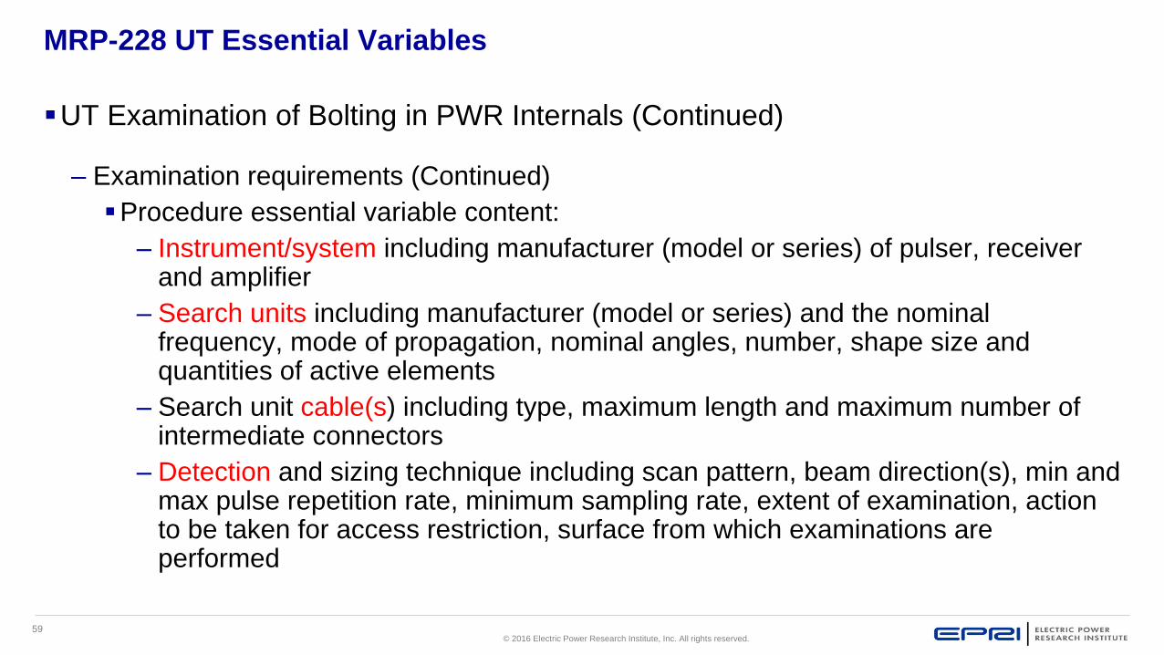
59© 2016 Electric Power Research Institute, Inc. All rights reserved.
MRP-228 UT Essential Variables
UT Examination of Bolting in PWR Internals (Continued)
– Examination requirements (Continued)
Procedure essential variable content:
– Instrument/system including manufacturer (model or series) of pulser, receiver and amplifier
– Search units including manufacturer (model or series) and the nominal frequency, mode of propagation, nominal angles, number, shape size and quantities of active elements
– Search unit cable(s) including type, maximum length and maximum number of intermediate connectors
– Detection and sizing technique including scan pattern, beam direction(s), min and max pulse repetition rate, minimum sampling rate, extent of examination, action to be taken for access restriction, surface from which examinations are performed

60© 2016 Electric Power Research Institute, Inc. All rights reserved.
MRP-228 UT Essential Variables
UT Examination of Bolting in PWR Internals (Continued)
– Examination requirements (Continued)
Procedure essential variable content: (Continued)
– Calibration techniques
– Calibration and examination data to be recorded
– Method of data recording and recording equipment used
– Method and criteria for the analysis and discrimination of indications
– Surface preparation requirements
– The procedure shall specify a single value or range of values for the items
listed above

61© 2016 Electric Power Research Institute, Inc. All rights reserved.
MRP-228 GENERAL PROCEDURES
Recording Flaws
UT Examination of Bolting in PWR Internals (Continued)
– Classification of Indications
Indications shall be classified as either relevant or non-relevant. If an indication cannot be
classified during initial examinations, additional re-looks shall be performed. The UT
procedure shall contain instructions describing how the data will be interpreted and analyzed.
All relevant indications shall be reviewed by another UT Level II or Level III examiner.
– Documentation of Results
Documentation should, as a minimum, include the following: 1) the examination procedure
number and revision, date(s) of examination(s) and evaluation(s) and names of personnel
performing the examinations, and data review and analysis, 2) the location and extent of the
bolts examined, 3) a calculation of the percentage or number of bolts that were successfully
examined compared to the number scheduled for examination, and 4) the number and
location of bolts with flaw indications, including their unique identification, if available.

62© 2016 Electric Power Research Institute, Inc. All rights reserved.
MRP-228 GENERAL PROCEDURES
Technical Justifications 2.4.9
UT Examination of Bolting in PWR Internals (Continued)
– Technical Justifications and Capability Studies
Ultrasonic examination systems are required to be qualified by a Technical Justification as
described in Section 2.1 of MRP-228. The organization that prepared the procedure will also
be responsible for preparing the Technical Justification. The utilities are responsible for
approving the Technical Justification and may request that the MRP assist by reviewing the
Technical Justification.
TJ requirements based on guidance of ASME B&PV Code, Section V, Article 14, not
including Appendix II
Capability study to support TJ is required that meets the guidance of intermediate rigor using
blind testing similar to ASME Section XI, Appendix VIII
MRP Inspection TAC provides guidance for conducting capability studies on MRP website
(MRP Letter 2013-011).

63© 2016 Electric Power Research Institute, Inc. All rights reserved.
MRP-228 GENERAL PROCEDURES
Personnel & Procedure Qualifications for Other NDE 2.5
Personnel Qualification
–To examine internals personnel shall be certified to at least a Level II examiner
in the applicable method in accordance with an employer’s written practice
–Utilities shall conduct site-specific training on utility-specific procedural
requirements, configuration details, previous examination results, operation of
examination equipment, specific outage inspection scope, and any other
pertinent information related to examination, evaluation and reporting, as
applicable. The training is to be conducted prior to inspections for each
refueling outage. The training shall be documented by the utility with the actual
training time required to be determined based on the outage inspection scope,
the inspection history, and the familiarity of data evaluators with the site.
64© 2016 Electric Power Research Institute, Inc. All rights reserved.
MRP-228 GENERAL PROCEDURES
Personnel & Procedure Qualifications for Other NDE 2.5
Personnel Qualification (Cont’d)
– Utilities shall ensure that all personnel involved in the evaluation of examination
data meet the requirements of this document.
Procedure Qualification
– Utilities are responsible for approving the Technical Justification prepared in
accordance with Section 2.1 and they may request that the MRP assist in this
review.
– TJs are required for all NDE procedures other than VT-1, VT-3 and EVT-1

65© 2016 Electric Power Research Institute, Inc. All rights reserved.
Other NDE Checklists

66© 2016 Electric Power Research Institute, Inc. All rights reserved.
MRP-228 GENERAL PROCEDURES
Mockups
Use of MRP Mockups
– Mockups developed by the MRP
– MRP-228, Section 2.2 is a guide for the use of MRP developed mockups
– Mockups are used primarily for training

67© 2016 Electric Power Research Institute, Inc. All rights reserved.
MRP-228 GENERAL PROCEDURES
EPRI B&W Mockups
Example B&W Design Mockups
– Baffle Bolts
– Thermal Shield Bolts
– Lower Core Barrel Bolts
– Locking Devices
Various B&W MRP Mockups: Baffle bolting and formers, and various bolting.

68© 2016 Electric Power Research Institute, Inc. All rights reserved.
MRP-228 Westinghouse Design Mockups
Westinghouse Design Mockups (Thermal shield flexure)

69© 2016 Electric Power Research Institute, Inc. All rights reserved.
Questions, Discussion

© 2016 Electric Power Research Institute, Inc. All rights reserved.
Boiling Water Reactor
Vessel and Internals
(BWRVIP) Guidelines
Chuck Wirtz
EPRI BWRVIP Integration Task Manager
International LWR Materials Reliability Conference
August 1, 2016

2© 2016 Electric Power Research Institute, Inc. All rights reserved.
BWRVIP Guidelines
BWRVIP Guidelines can be grouped into the following categories:
Safety Assessments
Administrative Guidelines
Inspection and Flaw Evaluation (I&E) Guidelines
Reports that Support Flaw Evaluations
Nondestructive Examination (NDE) Guidelines
Repair Guidelines
Integrated Surveillance Program
Water Chemistry Guidelines

3© 2016 Electric Power Research Institute, Inc. All rights reserved.
BWRVIP Guidelines to Manage Degradation
Assessment Inspection Repair/Replace Mitigation
Component (I&E) Guidelines Guidelines Design Criteria Recommendations
Core shroud BWRVIP-76-A BWRVIP-03 BWRVIP-02-A/-04-A BWRVIP-62, Rev. 1/-190, Rev. 1
Core spray BWRVIP-18, Rev. 2 BWRVIP-03 BWRVIP-16-A/-19-A/-34 N/A
Shroud support BWRVIP-38 BWRVIP-03 BWRVIP-52-A BWRVIP-62, Rev. 1/-190, Rev. 1
Top Guide BWRVIP-26-A BWRVIP-03 BWRVIP-50-A N/A
Core Plate BWRVIP-25 BWRVIP-03 BWRVIP-50-A BWRVIP-62, Rev. 1/-190, Rev. 1
SLC BWRVIP-27-A BWRVIP-03 BWRVIP-53-A BWRVIP-62, Rev. 1/-190, Rev. 1
Jet pump assembly BWRVIP-41, Rev. 3 BWRVIP-03 BWRVIP-51-A BWRVIP-62, Rev. 1/-190, Rev. 1
CRD guide/stub tube BWRVIP-47-A BWRVIP-03 BWRVIP-17/-55-A/-58-A BWRVIP-62, Rev. 1/-190, Rev. 1
In-core housing/dry tube BWRVIP-47-A BWRVIP-03 BWRVIP-17/-55-A BWRVIP-62, Rev. 1/-190, Rev. 1
Instrument penetrations BWRVIP-49-A BWRVIP-03 BWRVIP-57-A BWRVIP-62, Rev. 1/-190, Rev. 1
LPCI coupling BWRVIP-42, Rev. 2 BWRVIP-03 BWRVIP-56-A N/A
Vessel ID brackets BWRVIP-48-A BWRVIP-03 BWRVIP-52-A BWRVIP-62, Rev. 1/-190, Rev. 1
Reactor pressure vessel BWRVIP-74-A N/A N/A N/A
Primary system piping BWVIP-75-A N/A N/A BWRVIP-62, Rev. 1/-190, Rev. 1
Steam dryer BWRVIP-139-A BWRVIP-03 BWRVIP-181 N/A
Access hole cover BWRVIP-180 BWRVIP-03 BWRVIP-217 BWRVIP-62, Rev. 1/-190, Rev. 1
Top guide grid beam BWRVIP-183 BWRVIP-03 BWRVIP-50-A N/A
Bottom head drain line BWRVIP-205 N/A BWRVIP-208 N/A

4© 2016 Electric Power Research Institute, Inc. All rights reserved.
Safety Assessments
BWRVIP-06, “Safety Assessment of BWR Reactor Internals”, published
October 1995
– Purpose:
Perform deterministic safety assessments of all internals, penetrations and attachments (non-safety received a less rigorous assessment)
– Consider BWR/2 – BWR/6 components and subcomponents
– Configurations were “as designed”, did not account for plant modifications
Identify short and long term actions to assure safe operation assuming component cracking
Provide a tool to assess other cracking that might occur
– Scope: Components categorized as “safety-related” are those that can be relied upon to remain functional during and following design basis events to ensure (10CFR50.2):
(1) The integrity of the reactor coolant pressure boundary
(2) The capability to shut down the reactor and maintain it in a safe shutdown condition; or
(3) The capability to prevent or mitigate the consequences of accidents which could result in potential offsite exposures comparable to 10CFR100

5© 2016 Electric Power Research Institute, Inc. All rights reserved.
Safety Assessments
High Priority
– Shroud
– Core Spray Piping and Sparger
– Shroud Support
– Top Guide
– Core Plate
– Standby Liquid Control System
Medium Priority
– Jet Pump Assembly
Low Priority
– Control Rod Drive Guide Tube and Stub Tubes
– Incore Housing and Dry Tubes
– Instrument Penetrations
– RPV Attachments
– Low Pressure Coolant Injection (LPCI) Coupling
Inspection Prioritizations resulting from the BWRVIP-06 Ground Work:

6© 2016 Electric Power Research Institute, Inc. All rights reserved.
Safety Assessments
BWRVIP-09, “Quantitative Safety Assessment of BWR Reactor Internals”,
published May 1997
– Purpose: To provide additional confidence in BWRVIP-06 and further assess impact of component failure, the BWRVIP perform probabilistic risk assessment (PRA) of components whose failures could result increased core damage frequency.
– Scope: The eight components identified by BWRVIP-06 whose falures, combined with low probability events, may result in increased core damage frequency:
– Results: Concluded no CDF concerns, no short-term actions were needed, and supported the BWRVIPs prioritization of components for inspection and evaluation guidelines (I&EG) development
1. Control rod guide tubes, housing and stub tubes
2. Core plate
3. Core spray piping
4. Core spray spargers
5. Jet pump assemblies
6. LPCI coupling
7. Access hole covers
8. Top guide grid

7© 2016 Electric Power Research Institute, Inc. All rights reserved.
Administrative Guideline
BWRVIP-94: BWR Vessel and Internals Project, Program Implementation Guide, is the overall program guidance document for the BWRVIP program:
Specifies having a BWRVIP Program is “Mandatory” under the implementation requirements of NEI 03-08 while other elements of BWRVIP-94 are “needed”
Provides guidance to ensure owners consistently implement BWRVIP guidelines
Incorporates the relevant guidance from NEI Initiative 03-08, “Guidelines for the Management of Materials Issues” (NEI 03-08), including
– Roles and Responsibilities of the BWRVIP
– Roles and Responsibilities of Individual Utilities
Defines
– BWRVIP Member’s responsibilities
– Utility requirements
– What constitutes a BWRVIP Program
– Support elements of a program
– Regulatory commitments
Provides
– Guidance on deviation dispositions
– expectations regarding emergent issues

8© 2016 Electric Power Research Institute, Inc. All rights reserved.
BWRVIP-94 Utility Responsibilities
Have a BWRVIP Program
Have a Water Chemistry Control Program
Maintain the Program in a current condition– Revise the program to comply with Executive Committee approved
documents
– Implement the new guidance within 2 refueling outages, unless otherwise specified by the BWRVIP
Update the program, and
Perform initial examinations, but
Cannot implement less conservative criteria when previous version is NRC-approved (e.g., previous version is a “-A” version)
Conduct BWRVIP activities under 10CFR50 Appendix B QA Program

9© 2016 Electric Power Research Institute, Inc. All rights reserved.
BWRVIP-94 Utility Responsibilities, cont’d
Report Inspection/Repair results
Conduct self-assessments of their BWRVIP program
Communicate new “emerging” materials issues promptly
Process a Deviation Disposition (DD) when deviating from
“Mandatory” or Needed” criteria
– Includes inspection strategies, frequencies, techniques and evaluation of
results
– DD shall include technical basis assessing impact and acceptability of the
deviation

10© 2016 Electric Power Research Institute, Inc. All rights reserved.
BWRVIP-94 BWRVIP responsibilities
Developing and maintaining a strategic work plan
Maintain an up-to-date listing of BWRVIP documents and their NEI 03-08
classification
– Listing is in BWRVIP Cockpit
Develop and maintain/revise guidelines as warranted
– Incorporate new OE
– Incorporate new research or technical information
Interpret BWRVIP guidelines
– Will interpret requirements
– Will not use interpretation to change guidelines
Resolving materials issues that fall within the scope of the BWRVIP
Regulatory interface for major materials issues

11© 2016 Electric Power Research Institute, Inc. All rights reserved.
Inspection and Evaluation Guidelines (I&EG)
There is an I&EG document for each internal component
addressed by BWRVIP
There are also I&EGs for the reactor vessel attachments,
penetrations, and pressure boundary piping
– In some instances, e.g., small bore penetrations, the BWRVIP
Guidelines simply refer to ASME for the inspection requirements
These documents are the practical core of materials management
for the internals and primary pressure boundary
They tell you what to inspect, when to inspect it, and how to
evaluate the results

12© 2016 Electric Power Research Institute, Inc. All rights reserved.
Assessment Inspection Repair/Replace Mitigation
Component (I&E) Guidelines Guidelines Design Criteria Recommendations
Core shroud BWRVIP-76-A BWRVIP-03 BWRVIP-02-A/-04-A BWRVIP-62, Rev. 1/-190, Rev. 1
Core spray BWRVIP-18, Rev. 2 BWRVIP-03 BWRVIP-16-A/-19-A/-34 N/A
Shroud support BWRVIP-38 BWRVIP-03 BWRVIP-52-A BWRVIP-62, Rev. 1/-190, Rev. 1
Top Guide BWRVIP-26-A BWRVIP-03 BWRVIP-50-A N/A
Core Plate BWRVIP-25 BWRVIP-03 BWRVIP-50-A BWRVIP-62, Rev. 1/-190, Rev. 1
SLC BWRVIP-27-A BWRVIP-03 BWRVIP-53-A BWRVIP-62, Rev. 1/-190, Rev. 1
Jet pump assembly BWRVIP-41, Rev. 3 BWRVIP-03 BWRVIP-51-A BWRVIP-62, Rev. 1/-190, Rev. 1
CRD guide/stub tube BWRVIP-47-A BWRVIP-03 BWRVIP-17/-55-A/-58-A BWRVIP-62, Rev. 1/-190, Rev. 1
In-core housing/dry tube BWRVIP-47-A BWRVIP-03 BWRVIP-17/-55-A BWRVIP-62, Rev. 1/-190, Rev. 1
Instrument penetrations BWRVIP-49-A BWRVIP-03 BWRVIP-57-A BWRVIP-62, Rev. 1/-190, Rev. 1
LPCI coupling BWRVIP-42, Rev. 2 BWRVIP-03 BWRVIP-56-A N/A
Vessel ID brackets BWRVIP-48-A BWRVIP-03 BWRVIP-52-A BWRVIP-62, Rev. 1/-190, Rev. 1
Reactor pressure vessel BWRVIP-74-A N/A N/A N/A
Primary system piping BWVIP-75-A N/A N/A BWRVIP-62, Rev. 1/-190, Rev. 1
Steam dryer BWRVIP-139-A BWRVIP-03 BWRVIP-181 N/A
Access hole cover BWRVIP-180 BWRVIP-03 BWRVIP-217 BWRVIP-62, Rev. 1/-190, Rev. 1
Top guide grid beam BWRVIP-183 BWRVIP-03 BWRVIP-50-A N/A
Bottom head drain line BWRVIP-205 N/A BWRVIP-208 N/A
Inspection and Evaluation Guidelines

13© 2016 Electric Power Research Institute, Inc. All rights reserved.
Contents of I&E Guidelines 1 of 5
Description of component
Discussion of susceptibility to IGSCC
Discussion of consequences of failure of each location
Inspection history
Inspection requirements
Evaluation methods
Reporting requirements (now addressed in BWRVIP-94)
(Note: Format differs somewhat among I&E Guidelines)

14© 2016 Electric Power Research Institute, Inc. All rights reserved.
Contents of I&E Guidelines 2 of 5
Component Descriptions include:– Sketches show location of welds, bolted joints, etc.
– Locations labeled for identification purposes
– General plant variations shown (BWR/2 vs. BWR/6)
In some cases, plant specific configurations shown
– Configuration information is based on best available design information (BWRVIP-15)
– As-built configuration may be significantly different
Susceptibility Discussion includes:– Which locations are likely to experience degradation through IGSCC or other mechanisms,
and which are not
– Susceptibility is an input to inspection requirements
– Non-susceptible locations do not normally require inspection

15© 2016 Electric Power Research Institute, Inc. All rights reserved.
Contents of I&E Guidelines 3 of 5
Safety Consequence– Safety consequences of failure for each location discussed
– Safety consequence is an input to inspection requirements
– Locations with higher safety impact generally have more stringent and/or more frequent
examinations
Jet pump locations below inlet mixer more critical to preserve 2/3 core height flooded
during a LOCA
– Locations not having adverse safety consequences are generally not required to be
inspected
– Guidelines recommend that there may be economic reasons to inspect additional locations
Inspection History– Review of inspections performed at the time of report preparation
– List of indications observed
– Secondary input to inspection requirements

16© 2016 Electric Power Research Institute, Inc. All rights reserved.
Contents of I&E Guidelines 4 of 5
Inspection requirements include:– List of locations to inspect– Schedule for “baseline” inspection – Inspection methods allowed or required for each location
EVT-1: enhanced visual with cleaning requirements
VT-1: close visual examination
VT-3: general visual examination
UT: ultrasonic examination
ET: eddy current examination
– Reinspection criteria Frequency – based on inspection method used sample size
– Scope expansion Additional inspections if cracks are found
– Alternatives to inspection Specific repairs or analyses to eliminate inspections

17© 2016 Electric Power Research Institute, Inc. All rights reserved.
Contents of I&E Guidelines 5 of 5
Flaw evaluation guidance describes acceptable procedures for evaluation of flaws
– Structural analysis techniques, in some cases, equations
Limit load
Linear elastic fracture mechanics
Elastic plastic fracture mechanics
– Loads to be considered
– Effects of environment (e.g. water chemistry, fluence, etc.)
– Assumptions regarding cracking in un-inspected regions
– Consideration of NDE uncertainty (if applicable)
– Leakage calculations (if applicable)
Refer to appropriate BWRVIP guidelines to be used for crack growth rates and
fracture toughness
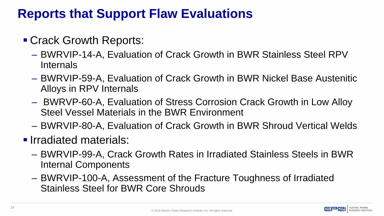
18© 2016 Electric Power Research Institute, Inc. All rights reserved.
Reports that Support Flaw Evaluations
Crack Growth Reports:
– BWRVIP-14-A, Evaluation of Crack Growth in BWR Stainless Steel RPV Internals
– BWRVIP-59-A, Evaluation of Crack Growth in BWR Nickel Base Austenitic Alloys in RPV Internals
– BWRVP-60-A, Evaluation of Stress Corrosion Crack Growth in Low Alloy Steel Vessel Materials in the BWR Environment
– BWRVIP-80-A, Evaluation of Crack Growth in BWR Shroud Vertical Welds
Irradiated materials:
– BWRVIP-99-A, Crack Growth Rates in Irradiated Stainless Steels in BWR Internal Components
– BWRVIP-100-A, Assessment of the Fracture Toughness of Irradiated Stainless Steel for BWR Core Shrouds

19© 2016 Electric Power Research Institute, Inc. All rights reserved.
Nondestructive Examination (NDE) Guidelines
BWRVIP-03: BWR Vessel and Internals Project, Reactor Pressure Vessel and Internals Examination Guidelines, is the BWRVIP’s guidance document for NDE used to perform BWRVIP inspections
Contains the generic procedure requirements for enhanced visual examinations (EVT-1), ultrasonic (UT), and Eddy Current of BWR vessel internals
Provides guidelines for the use of BWRVIP mockups and the protocol for NDE Technique Demonstrations on the mockups
Provides guidelines for determining NDE Technique Uncertainty and Inspection Tool Positioning Uncertainty
Documents vendor technique demonstrations (mostly UT) for the different BWR vessel internal components (over 270 demonstrations to date)
Revised annually to incorporate new technique demonstrations and any other updates (currently at Revision 18)

20© 2016 Electric Power Research Institute, Inc. All rights reserved.
Assessment Inspection Repair/Replace Mitigation
Component (I&E) Guidelines Guidelines Design Criteria Recommendations
Core shroud BWRVIP-76-A BWRVIP-03 BWRVIP-02-A/-04-A BWRVIP-62, Rev. 1/-190, Rev. 1
Core spray BWRVIP-18, Rev. 2 BWRVIP-03 BWRVIP-16-A/-19-A/-34 N/A
Shroud support BWRVIP-38 BWRVIP-03 BWRVIP-52-A BWRVIP-62, Rev. 1/-190, Rev. 1
Top Guide BWRVIP-26-A BWRVIP-03 BWRVIP-50-A N/A
Core Plate BWRVIP-25 BWRVIP-03 BWRVIP-50-A BWRVIP-62, Rev. 1/-190, Rev. 1
SLC BWRVIP-27-A BWRVIP-03 BWRVIP-53-A BWRVIP-62, Rev. 1/-190, Rev. 1
Jet pump assembly BWRVIP-41, Rev. 3 BWRVIP-03 BWRVIP-51-A BWRVIP-62, Rev. 1/-190, Rev. 1
CRD guide/stub tube BWRVIP-47-A BWRVIP-03 BWRVIP-17/-55-A/-58-A BWRVIP-62, Rev. 1/-190, Rev. 1
In-core housing/dry tube BWRVIP-47-A BWRVIP-03 BWRVIP-17/-55-A BWRVIP-62, Rev. 1/-190, Rev. 1
Instrument penetrations BWRVIP-49-A BWRVIP-03 BWRVIP-57-A BWRVIP-62, Rev. 1/-190, Rev. 1
LPCI coupling BWRVIP-42, Rev. 2 BWRVIP-03 BWRVIP-56-A N/A
Vessel ID brackets BWRVIP-48-A BWRVIP-03 BWRVIP-52-A BWRVIP-62, Rev. 1/-190, Rev. 1
Reactor pressure vessel BWRVIP-74-A N/A N/A N/A
Primary system piping BWVIP-75-A N/A N/A BWRVIP-62, Rev. 1/-190, Rev. 1
Steam dryer BWRVIP-139-A BWRVIP-03 BWRVIP-181 N/A
Access hole cover BWRVIP-180 BWRVIP-03 BWRVIP-217 BWRVIP-62, Rev. 1/-190, Rev. 1
Top guide grid beam BWRVIP-183 BWRVIP-03 BWRVIP-50-A N/A
Bottom head drain line BWRVIP-205 N/A BWRVIP-208 N/A
Nondestructive Evaluation Guidelines

21© 2016 Electric Power Research Institute, Inc. All rights reserved.
Repair Guidelines
Repair Design Criteria Guidelines
– Individual BWRVIP reports that provide general design guidance and acceptance criteria for permanent and temporary repair for various BWR vessel internal components (see next slide)
Supporting Repair Guidelines
– BWRVIP-84, Revision 2-A, Guidelines for Selection and Use of Materials for Repairs to BWR Internal Components
– BWRVIP-95-A, Guide for Format and Content of BWRVIP Repair Submittals
– BWRVIP-97-A, Guidelines for Performing Weld Repairs to Irradiated BWR Internals

22© 2016 Electric Power Research Institute, Inc. All rights reserved.
Assessment Inspection Repair/Replace Mitigation
Component (I&E) Guidelines Guidelines Design Criteria Recommendations
Core shroud BWRVIP-76-A BWRVIP-03 BWRVIP-02-A/-04-A BWRVIP-62, Rev. 1/-190, Rev. 1
Core spray BWRVIP-18, Rev. 2 BWRVIP-03 BWRVIP-16-A/-19-A/-34 N/A
Shroud support BWRVIP-38 BWRVIP-03 BWRVIP-52-A BWRVIP-62, Rev. 1/-190, Rev. 1
Top Guide BWRVIP-26-A BWRVIP-03 BWRVIP-50-A N/A
Core Plate BWRVIP-25 BWRVIP-03 BWRVIP-50-A BWRVIP-62, Rev. 1/-190, Rev. 1
SLC BWRVIP-27-A BWRVIP-03 BWRVIP-53-A BWRVIP-62, Rev. 1/-190, Rev. 1
Jet pump assembly BWRVIP-41, Rev. 3 BWRVIP-03 BWRVIP-51-A BWRVIP-62, Rev. 1/-190, Rev. 1
CRD guide/stub tube BWRVIP-47-A BWRVIP-03 BWRVIP-17/-55-A/-58-A BWRVIP-62, Rev. 1/-190, Rev. 1
In-core housing/dry tube BWRVIP-47-A BWRVIP-03 BWRVIP-17/-55-A BWRVIP-62, Rev. 1/-190, Rev. 1
Instrument penetrations BWRVIP-49-A BWRVIP-03 BWRVIP-57-A BWRVIP-62, Rev. 1/-190, Rev. 1
LPCI coupling BWRVIP-42, Rev. 2 BWRVIP-03 BWRVIP-56-A N/A
Vessel ID brackets BWRVIP-48-A BWRVIP-03 BWRVIP-52-A BWRVIP-62, Rev. 1/-190, Rev. 1
Reactor pressure vessel BWRVIP-74-A N/A N/A N/A
Primary system piping BWVIP-75-A N/A N/A BWRVIP-62, Rev. 1/-190, Rev. 1
Steam dryer BWRVIP-139-A BWRVIP-03 BWRVIP-181 N/A
Access hole cover BWRVIP-180 BWRVIP-03 BWRVIP-217 BWRVIP-62, Rev. 1/-190, Rev. 1
Top guide grid beam BWRVIP-183 BWRVIP-03 BWRVIP-50-A N/A
Bottom head drain line BWRVIP-205 N/A BWRVIP-208 N/A
Repair Design Criteria Guidelines

23© 2016 Electric Power Research Institute, Inc. All rights reserved.
Water Chemistry Guidelines
BWRVIP-190, Revision 1, BWR Water Chemistry Guidelines– Volume 1: Mandatory, Needed, and Good Practice Guidance
– Volume 2: Technical Basis
BWRVIP-62, Technical Basis for Inspection Relief for BWR Internal Components with Hydrogen Injection– BWRVIP-62-A, currently the NRC approved version, does not
include current practice of online noble metals chemical addition (OLNC)
– BWRVIP-62, Revision 1, includes OLNC and is currently under NRC review

24© 2016 Electric Power Research Institute, Inc. All rights reserved.
Assessment Inspection Repair/Replace Mitigation
Component (I&E) Guidelines Guidelines Design Criteria Recommendations
Core shroud BWRVIP-76-A BWRVIP-03 BWRVIP-02-A/-04-A BWRVIP-62, Rev. 1/-190, Rev. 1
Core spray BWRVIP-18, Rev. 2 BWRVIP-03 BWRVIP-16-A/-19-A/-34 N/A
Shroud support BWRVIP-38 BWRVIP-03 BWRVIP-52-A BWRVIP-62, Rev. 1/-190, Rev. 1
Top Guide BWRVIP-26-A BWRVIP-03 BWRVIP-50-A N/A
Core Plate BWRVIP-25 BWRVIP-03 BWRVIP-50-A BWRVIP-62, Rev. 1/-190, Rev. 1
SLC BWRVIP-27-A BWRVIP-03 BWRVIP-53-A BWRVIP-62, Rev. 1/-190, Rev. 1
Jet pump assembly BWRVIP-41, Rev. 3 BWRVIP-03 BWRVIP-51-A BWRVIP-62, Rev. 1/-190, Rev. 1
CRD guide/stub tube BWRVIP-47-A BWRVIP-03 BWRVIP-17/-55-A/-58-A BWRVIP-62, Rev. 1/-190, Rev. 1
In-core housing/dry tube BWRVIP-47-A BWRVIP-03 BWRVIP-17/-55-A BWRVIP-62, Rev. 1/-190, Rev. 1
Instrument penetrations BWRVIP-49-A BWRVIP-03 BWRVIP-57-A BWRVIP-62, Rev. 1/-190, Rev. 1
LPCI coupling BWRVIP-42, Rev. 2 BWRVIP-03 BWRVIP-56-A N/A
Vessel ID brackets BWRVIP-48-A BWRVIP-03 BWRVIP-52-A BWRVIP-62, Rev. 1/-190, Rev. 1
Reactor pressure vessel BWRVIP-74-A N/A N/A N/A
Primary system piping BWVIP-75-A N/A N/A BWRVIP-62, Rev. 1/-190, Rev. 1
Steam dryer BWRVIP-139-A BWRVIP-03 BWRVIP-181 N/A
Access hole cover BWRVIP-180 BWRVIP-03 TBD BWRVIP-62, Rev. 1/-190, Rev. 1
Top guide grid beam BWRVIP-183 BWRVIP-03 BWRVIP-50-A N/A
Bottom head drain line BWRVIP-205 N/A BWRVIP-208 N/A
Mitigation/Water Chemistry

25© 2016 Electric Power Research Institute, Inc. All rights reserved.
Integrated Surveillance Program
The Integrated Surveillance Program (ISP) was developed by the BWRVIP and is used by all U.S. BWRs to meet 10CFR50, Appendix H, RPV material surveillance program requirements
BWRVIP-86, Revision 1-A, Updated BWR Integrated Surveillance Program (ISP) Implementation Plan– Provides the ISP test matrix and schedule
– Provides ISP administration and implementation guidelines
– Revision 1 extended the ISP for License Renewal
BWRVIP-135, Integrated Surveillance Program (ISP) Data Source Book and Plant Evaluations– Documents plant-specific ISP data evaluations
– Provides guidelines for use of ISP data

26© 2016 Electric Power Research Institute, Inc. All rights reserved.
Together…Shaping the Future of Electricity

© 2016 Electric Power Research Institute, Inc. All rights reserved.
Jack SpannerEPRI
BWR/PWR In-Vessel Inspection Workshop
International Light Water Reactors Material Reliability Conference
Chicago, ILAugust 1, 2016
PWR Inspection
Experiences, Results
and Lessons Learned

2© 2016 Electric Power Research Institute, Inc. All rights reserved.
MRP-227 Inspection Results
Ginna
Surry Unit 1& 2
Kewaunee (Guide card only)
HB Robinson
Oconee 1, 2 & 3
Point Beach 1 & 2
North Anna Unit 1& 2
Prairie Island 1 & 2
Palisades
Millstone 3
Three Mile Island 1
Turkey Point 3 & 4
Indian Point 2
Salem 1
Catawba 2

3© 2016 Electric Power Research Institute, Inc. All rights reserved.
Contact Information
EPRI MRP Project Manager: Jack Spanner– Phone: +1-704-595-2565
– E-Mail: [email protected]
EPRI MRP Project Manager: Kyle Amberge– Email: [email protected]
– Phone: +1-650-855-2039

4© 2016 Electric Power Research Institute, Inc. All rights reserved.
Recent Baffle-Former-Bolting Inspection
Findings
DC Cook 2, 4-loop Westinghouse plant, 2010, visual only (Ref. TB-12-5)
– 18 bolts with visual indications with
visual clustering
– UT not performed
– 40 bolts were replaced
Example
Baffle-
Former
Bolt
Locations
Thermal
Shield
Core Barrel
Baffle
PlateFormer
Plate

5© 2016 Electric Power Research Institute, Inc. All rights reserved.
Recent Baffle-Former-Bolting Inspection
Findings
Indian Point 2, 4-loop Westinghouse plant, 3/2016, VT-3/UT (Ref. MRP-2016-007)– Markings on periphery of neighboring fuel assembly identified (no fuel failure).
– Inspections identified 227 with visual degradation or UT indications
Includes 14 that were not inspectable
– Total number of baffle-former bolts 832
– Number of bolts inspected UT 787
– Number with no UT indications 605
– Number of bolts with UT indications 182
– Number with head-shank indications 182
– Number of bolts not inspected due
to Confirmed Visual Indications 31
– Number of bolts not inspected due to
surface or lock-bar weld condition 14
Replaced 276 bolts
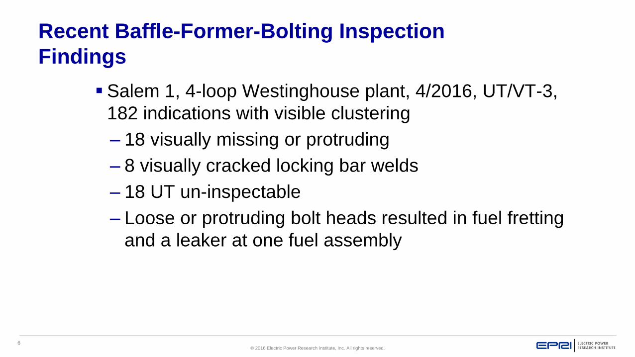
6© 2016 Electric Power Research Institute, Inc. All rights reserved.
Recent Baffle-Former-Bolting Inspection
Findings
Salem 1, 4-loop Westinghouse plant, 4/2016, UT/VT-3,
182 indications with visible clustering
– 18 visually missing or protruding
– 8 visually cracked locking bar welds
– 18 UT un-inspectable
– Loose or protruding bolt heads resulted in fuel fretting
and a leaker at one fuel assembly

7© 2016 Electric Power Research Institute, Inc. All rights reserved.
Other Recent Baffle-Former-Bolting
Inspection Findings Surry 1, 3-loop Westinghouse plant, 2010, UT (Ref. MRP-219)
1 indication, none replaced
Surry 2, 3-loop Westinghouse plant, 2011, UT 2 indications, none replaced
HB Robinson, 3-loop Westinghouse plant, 2013, UT 8 indications, none replaced
Turkey Point 3, 3-loop Westinghouse plant, 2015, UT zero indications out of 305 inspected to date
Oconee 3, B&W plant, 2014, UT 1 indication out of 863 inspected, 1 un-inspectable, none replaced
Actions for BFBs are being addressed by BFB Focus Group
– Alert letter issued by PMMP-MRP 2016-014 for US plants
– Interim Guidance Letter MRP 2016-021 issued July 25, 2016: NSAL 16-01

8© 2016 Electric Power Research Institute, Inc. All rights reserved.
By the Numbers*Through Fall of 2014
15 Units begun or completed MRP inspections
959 W guide tube flange welds inspected
2427 Inches of irradiated welds inspected (approx.)
9125 Inches of non-irradiated welds inspected (approx.)
2226 CASS items inspected
8887 Baffle bolts inspected**
1306 B&W high strength bolts inspected
108 B&W baffle plates inspected
* All numbers approximate. Includes reported inspections through Fall 2014; some data includes retired plant; additional data may affect results slightly
** Includes retired unit

9© 2016 Electric Power Research Institute, Inc. All rights reserved.
By the Numbers (Cont’d)
Zero Guide Tube Flange weld indicationsZero irradiated girth weld indicationsOne non-irradiated weld indicationOne CASS VT-3 indication619 baffle bolt indications (4.9% of total)20 B&W high strength bolt indications (1.5% of
total)
{ All numbers approximate }
Guide Tube
Flange Welds

10© 2016 Electric Power Research Institute, Inc. All rights reserved.
Trends and Observations
Except for baffle-former bolts initial inspections at W and B&W and partial CE NSSS designs have not identified any major issues of concern
No macroscopic effects of void swelling– No distortions, cracking, or excessive bolting failure
High-strength nickel alloy clevis insert bolting failures– However, not in safety function load path
Baffle-Former Bolts are being actively addressed– 4-Loop down-flow plants
Guide card wear will require monitoring– MRP Interim guidance MRP-2014-006 issued (WCAP-17451-P)
Current results reduce uncertainty of damage mechanism predictions
Issues of greatest concern not seen– SCC of austenitic welded components not observed
Cracking currently limited to high strength bolting
– IASCC of welds not observed, indications limited to bolts
– Macroscopic effect of void swelling not observed
Some adjustments and efficiencies are needed, as expected with a ‘living’ program– Lessons learned incorporated into MRP-227 Rev. 1 and MRP-228 Rev. 2

11© 2016 Electric Power Research Institute, Inc. All rights reserved.
Ginna RV Internals MRP-227 Primary Item Exam Results
Summary of First Full MRP-227 Inspection
Guide Card Wear –100% VT-3 Inspection; no appreciable wear seen
CRGT Flange Welds –100% EVT-1 Inspection; no relevant indications identified
Core Barrel Upper Flange Weld –100% EVT-1 Inspection; no relevant indications
identified
Thermal Shield Flexures –100% VT-3; no relevant conditions
Core Barrel Baffle Edge Bolts & Seams –100% VT-3 (all 16 high fluence seams
for full length); no relevant conditions
Baffle Former Assembly –100% VT-3; no relevant conditions
Baffle Former Bolts –Replace or UT of plant specific minimum bolt pattern or
alternate bolts as selected by analysis; 1 bolt (or 1%) identified with a relevant UT
indication

12© 2016 Electric Power Research Institute, Inc. All rights reserved.
Surry Unit 1 MRP-227 Inspection Results
Only one UT indication detection of a likely flaw in one bolt,
identified as “C113”.
VT-3 identified two bolts deformed at the hex head points.
VT-3 also identified one baffle former bolt and one edge bolt
with one missing locking bar weld.

13© 2016 Electric Power Research Institute, Inc. All rights reserved.
Surry Unit 1
Baffle Bolt Inspections –Deformed Hex Head Points Missing Locking Bar Weld

14© 2016 Electric Power Research Institute, Inc. All rights reserved.
Surry Unit 2 Spring 2011 Baffle Bolt Inspections
Bolting material is Type 347 with external hex head with lock
bar slot.
All 1088 baffle to former bolts were UT and VT-3 examined.
All accessible 936 baffle edge bolts were VT-3 examined.
Baffle former bolt UT detected indications in two bolts,
identified as “A125” and “G63” located at the head to shank
region of the bolt.
With only two assumed failed bolts out of 1088, there is
significant margin above the industry evaluation guideline for
reactor internals, WCAP-17096 Revision 2.
15© 2016 Electric Power Research Institute, Inc. All rights reserved.
HB Robinson 2
No relevant indications
Circumferential indication identified at weld centerline around 345°, this was determined to be a Non-relevant fabrication anomaly.
1076/1088 BF bolts UT’d: 8 possible defects and 1 confirmed head-shank defect
Comments:– RNP Core Barrel protrudes out of Containment Vessel cavity water
approximately 18” while in the stand.
– A portion of this exam was done in the vessel, then in the stand.
– Specialized vendor tool with the capability to traverse the circumference of the Core Barrel was used for this inspection except when the Vessel Head Alignment Keys became an obstruction
– Another tool was utilized to inspect the remaining sections that were obstructed from view while the Core Barrel was in its stand

16© 2016 Electric Power Research Institute, Inc. All rights reserved.
Oconee Unit 1
Performed all MRP-227-A inspections in one outage
UT – 5 lower core barrel (LCB) with crack like indications
VT – 1 LCB locking device with a missing weld on one side and a small weld on
the other.
– The coverage for the VT-3 examination of 7 of the LCB bolts and their locking
devices was 40% to 50% due to the partial obstruction from the stand,
although 100% of the accessible surfaces were examined.
UT – 1 flow distributor bolt (#49) with crack like indication.
860 out of 864 baffle-to-former bolts
– 4 baffle-to-former bolts were un-inspectable due to large welds on locking bars.

17© 2016 Electric Power Research Institute, Inc. All rights reserved.
Oconee 1
Vent Valve Jack Screws
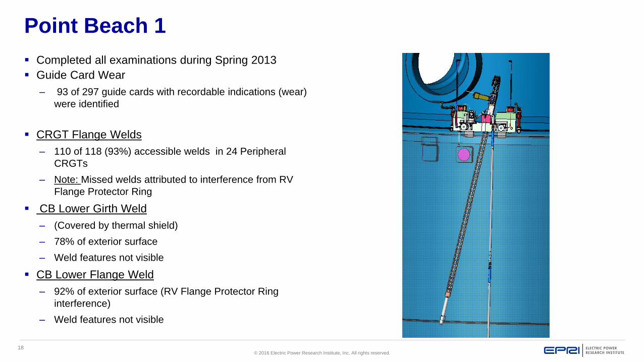
18© 2016 Electric Power Research Institute, Inc. All rights reserved.
Point Beach 1
Completed all examinations during Spring 2013
Guide Card Wear
– 93 of 297 guide cards with recordable indications (wear)
were identified
CRGT Flange Welds
– 110 of 118 (93%) accessible welds in 24 Peripheral
CRGTs
– Note: Missed welds attributed to interference from RV
Flange Protector Ring
CB Lower Girth Weld
– (Covered by thermal shield)
– 78% of exterior surface
– Weld features not visible
CB Lower Flange Weld
– 92% of exterior surface (RV Flange Protector Ring
interference)
– Weld features not visible

19© 2016 Electric Power Research Institute, Inc. All rights reserved.
Point Beach 1
Baffle Former Bolts
– 100% of 728 bolts examined by phased array UT
– 92% of bolts (670) provided relevant exam results
– Findings
– No failures found for 670 bolts with relevant exam results
Note: Non-relevant exam results attributed to bolt head geometry

20© 2016 Electric Power Research Institute, Inc. All rights reserved.
North Anna 1 and 2 and Millstone 3
Flux Thimble Tubes
– North Anna 1: No tubes required repositioning in 2012
• 50 of 50 tubes examined by eddy current
– North Anna 2: Two tubes required repositioning 3” in 2011
• 50 of 50 tubes examined by eddy current
– Millstone 3: No tubes required corrective action in 2013
• 58 of 58 tubes examined by eddy current

21© 2016 Electric Power Research Institute, Inc. All rights reserved.
Prairie Island 2
Baffle Former Bolts
– 100% of 728 bolts examined by phased array UT
– 75 bolts had indications
– 21 of these were in the head-shank
– 54 of these were in the shank (Unique)
– 653 bolts had no indications
Note: Bolt failures bounded by minimum pattern analysis per WCAP-
17096
Only B-F bolts were examined in 2013

22© 2016 Electric Power Research Institute, Inc. All rights reserved.
Prairie Island 1
Baffle Former Bolts
– 100% of 728 bolts examined by phased array UT
– 40 bolts had UT indications
– 24 of these were in the head-shank
– 15 of these were in the shank (Unique)
– 1 of these was in a thread
– 728 bolts had no VT-3 indications
Note: Bolt failures bounded by minimum pattern analysis per WCAP-17096
Only B-F bolts were examined in 2014

23© 2016 Electric Power Research Institute, Inc. All rights reserved.
Oconee 2
Lower Core Barrel Bolts
– UT of 108 out of 108 with one crack like indication
– VT-3 of 106 out of 108 bolts and locking devices due to stand obstruction
Baffle former bolts
– 863 out of 864 UT’d – one was un-inspectable
Flow Distributor bolts
– 96/96 bolts UT’d
– 2 bolts with crack like indications
The jack screw locking devices are not currently in MRP-227 but were identified as needing to be screened in A/LAI #2. Additional parts of the Vent Valves, including the jack screw locking devices, receive a ASME Section XI, Category B-N-3 VT-3 examination. 3 of 4 components were damaged or deformed

24© 2016 Electric Power Research Institute, Inc. All rights reserved.
Oconee 3
Lower Core Barrel Bolts
– UT of 108 out of 108 with three crack like indications -Seen in 1984
– VT-3 of 108 out of 108 bolts and locking devices
Upper Core Barrel Bolts
– UT of 120 out of 120 with two without back wall signal-Seen in 1984
– VT-3 of 120 out of 120 bolts and locking devices
Baffle former bolts
– 863 out of 864 UT’d – one had a crack like indication and one was un-inspectable
Flow Distributor bolts
– 96/96 bolts UT’d
– One bolt with crack like indication
IMI Guide tube spiders & spider to rib sections weld
– Two linear indications adjacent to guide tube spider casting weld
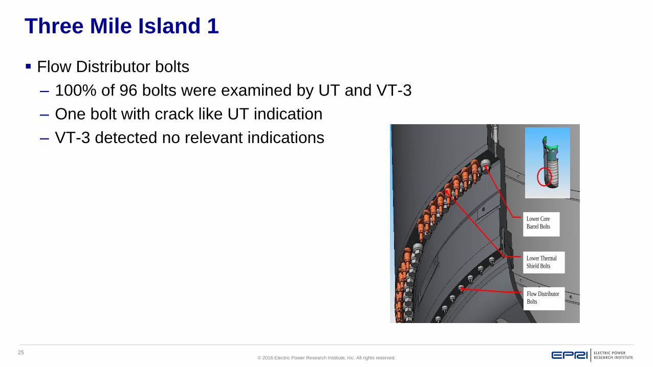
25© 2016 Electric Power Research Institute, Inc. All rights reserved.
Three Mile Island 1
Flow Distributor bolts
– 100% of 96 bolts were examined by UT and VT-3
– One bolt with crack like UT indication
– VT-3 detected no relevant indications
Flow Distributor
Bolts
Lower Thermal
Shield Bolts
Lower Core
Barrel Bolts

26© 2016 Electric Power Research Institute, Inc. All rights reserved.
Palisades (CE Design)
Core Shroud Assembly (Bolted)– Palisades detected slight 46 mil gap in shroud plate but verified from
fabrication
– Core Shroud Assembly Bolts
One core shroud bolt seated differently with locking bar bent and opening on the right side
Lower Cylinder Girth Welds– Upper GW – 100% coverage from inside
– Middle GW – 86.7% coverage from outside
– Upper GW – 76.7% coverage from outside
Instrument Guide Tubes– 15 locations, 8 welds each, 100% coverage

27© 2016 Electric Power Research Institute, Inc. All rights reserved.
Lessons Learned
Plants need to consider their internals stand design and its possible impact on examinations
– Consider exam challenges caused by close proximity of cavity walls, stand components, floor,
etc. that might interfere with examination access
– Recognize that accessibility to lower components may be limited
– Consider performing some examinations while internals suspended
– Shallow reactor cavities may also result in the internals extending above the water level when
placed in the stand
ALARA considerations may warrant the use of shielding
– Some examinations may best be performed before placing internals in stand
– Consider use of 3D modeling to evaluate impacts

28© 2016 Electric Power Research Institute, Inc. All rights reserved.
Lessons Learned
Shallow Cavities
Lower Girth Weld Tool employed for challenging conditions
– Core barrel exposed 4 feet above water
– Very high dose
– No access due to shield tanks
Tooling approach driven by extreme circumstances –
Dose rates in excess of 400 mR

29© 2016 Electric Power Research Institute, Inc. All rights reserved.
Lessons Learned
• Some inspections performed with core barrel in vessel
− Core Barrel: Upper Flange Weld and Upper Girth Weld from ID
• Others require core barrel removal from OD
• Common to split inspections over two or more outages
• Typically integrated with ASME Section XI examinations
• Special tooling often required
• Vendor crew of roughly 20 specialists required 24/7
• Vendor crew typically experienced on both PWRs and BWRs
• Owner oversight is important

30© 2016 Electric Power Research Institute, Inc. All rights reserved.
Together…Shaping the Future of Electricity