size reduction of low frequency micro strip patch antennas.kjvinoy/adspdf/sathya.pdf · size...
TRANSCRIPT

SIZE REDUCTION OF LOW FREQUENCY MICRO STRIP PATCH ANTENNAS WITH KOCH FRACTAL SLOTS
Sathya.K., M.Tech., CEDT, IISc, [email protected]
Under the guidance of Dr. K.J.Vinoy, Dept of ECE, IISc
ABSTRACT The development of communication engineering with integration technology demands size reduction of low frequency antennas as an important design perspective. In this work, a microstrip patch antenna with Koch shaped fractal slots implemented with a foam substrate (εr = 1.02) is shown to bring a size reduction of about 84 % compared to an ordinary microstrip patch antenna for the same resonant frequency. However size reduction comes at the cost of gain which is then enhanced to a good level by using 4- element array of the same antenna structure as an element reducing the size reduction to 33 %. A 2-element array is then designed to achieve good gain as well as appreciable size reduction of 66 %. 1. INTRODUCTION Microstrip antennas are popularly investigated due to their properties such as low profile, low cost, conformability and ease of integration with active devices. Reduction of antenna size becomes extremely important in wireless communications and hence it is desired to bring down the size of antenna while achieving the same performance of the large size antenna. Though there is a lower limit to the size of any antenna for a given resonant frequency, other important metrics like Gain and Bandwidth are drastically affected for small size antennas. Hence the idea is to balance between Gain and Size of the antenna. 2. SIZE REDUCTION OF MICRO STRIP PATCH ANTENNAS: For very low frequencies of MHz range, the size of the microstrip antennas becomes too large to be manageable. Many techniques have been used to reduce the size of antenna, such as
o using dielectric substrates with high permittivity [2], o applying resistive or reactive loading [3], o increasing the electrical length of antenna by optimizing its shape [4], o Utilization of strategically positioned notches on the patch antenna [5].
Various shapes of slots and slits have been embedded on patch antennas to reduce
their size. Slot antennas are used typically at frequencies between 300 MHz and 24 GHz. These antennas are popular because they can be cut out of whatever surface they are to be

mounted on, and have radiation patterns that are roughly omni directional. The currents travel around the slot perimeter increasing the electrical length. As such, a slotted small size antenna is made to perform equivalent to its larger counterpart. 3. FRACTAL SLOTS: Fractals mean broken or irregular fragments. Fractals describe a complex set of geometries ranging from self similar/ self-affine to other irregular structure. Fractals are generally composed of multiple copies of themselves at different scales and hence do not have a predefined size which makes their use in antenna design very promising. Fractal antenna engineering is an emerging field that employs fractal concepts for developing new types of antennas with notable characteristics.
Fractal shaped antennas show some interesting features which results from their geometrical properties. The unique features of fractals such as self-similarity and space filling properties enable the realization of antennas with interesting characteristics such as multi-band operation and miniaturization. A self-similar set is one that consists of scaled down copies of itself. This property of self-similarity of the fractal geometry aids in the design of fractal antennas with multiband characteristics. The self-similar current distribution on these antennas is expected to cause its multiband characteristics. The space-filling property of fractals tends to fill the area occupied by the antenna as the order of iteration is increased. Higher order fractal antennas exploit the space-filling property and enable miniaturization of antennas. Fractal antennas and arrays also exhibit lower side-lobe levels. Koch fractal geometry was originally introduced by a Helge von Koch in 1904. One starts with a straight line, called the initiator. This is partitioned into three equal parts, and the segment at the middle is replaced with two others of the same length. This is the first iterated version of the geometry and is called the generator. The process is reused in the generation of higher iterations. The number of iterations defines the order of the fractals. Shown below is the order-2 fractal structure used in this work
Fig 1: Order-2 Koch Fractal Structure

4. ANTENNA GEOMETRY AND OPERATION MECHANISM:
Fig 2: Microstrip Patch Antenna with 7 Fractal slots
Here a new reduced size microstrip antenna with ultra low profile features is presented [1]. This antenna configuration is shown in Fig. 2. The patch has dimensions of W × L. The Foam substrate which has a relative permittivity εr = 1.028 and thickness 6mm (240 mil) is used. The ground plane dimensions are Wg × Lg = 13.57cm× 12.82cm. The antenna is probe fed the feed locations given by Xf and Yf. Seven fractal defected microstrip structures (DMS) are excoriated from the patch’s surface. The lengths of these DMS’s are LD and their width are WD, and all have the same dimensions. These DMS’s are placed at equal distances lD from each other. Table 1 shows the designed dimensions (mm) that are used for the antenna.
W L Wg Lg WD LD lD Slot thickness
Xf Yf
135.7 128.2 165.7 158.2 22.4 123.8 18.5 2 15 63
Table 1. Designed dimensions of the antenna in mm.

Material Specifications: Conductor: Copper σ = 5.8E7 siemens/m t = 17um Substrate: Foam ε = 1.02 h = 6mm Simulation : Momentum Tool : ADS The proposed antenna is simulated using Advanced Design Studio (ADS). Fig. 3 shows the simulated and measured return loss versus frequency for the proposed antenna. As it can be seen in this figure, the first resonance occurs at 454 MHz, in comparison with the antenna with the equal size but without DMS’s that has a resonance frequency at 1.1 GHz. A rectangular patch with the resonance frequency at 440 MHz must have a total area of about 106704.77mm2. The proposed antenna with the total area of 17396.7mm2, operates at this frequency. So the size reduction of this approach is about 83.7% in comparison with ordinary patch.
Fig 3: Simulated Return Loss vs. Bandwidth
Thus it is understood that by inserting these defects on the antenna, surface current path’s is meandered and hence the electrical length of antenna is increased, although the physical length is left constant. So by increasing the electrical length of the antenna, the resonance frequency is decreased. This means that for an antenna with the same resonance frequency, the overall surface of antenna is decreased to a great amount.

Though excellent size reduction is achieved, the Gain obtained is very less around 2.731dB. The gain characteristics are shown in figure 4 below. Also the radiation pattern is plotted. The E plane polarization pattern is plotted in figure 5 below.
Fig 4: Gain vs. θ (degrees)
Fig 5.1: E plane polarization cross and coplanar

The simulated antenna impedance bandwidth for 10 dB return loss is also very narrow (below 1%). In order to increase the antenna bandwidth to an acceptable value, a matching circuit could be used at the feed line, to achieve a higher bandwidth [1]. Radiated Power Pattern: The following figure shows the 3D radiation pattern for the E.
Prad = 1.775mW
Figure 5.2: 3D Radiation Pattern of Power 5. GAIN ENHANCEMENT USING ARRAY PATTERN: 5.1 4-ELEMENT ARRAY: The antenna element designed above is repeated to get a 4-element array with their boundaries separated by 4 mm. Each of the elements is fed with a power 1/4th of the magnitude to obtain the superimposed radiation characteristics. This technique is shown to offer a very good gain but the size reduction has come down from 84% TO 33 %. The antenna structure is shown below:
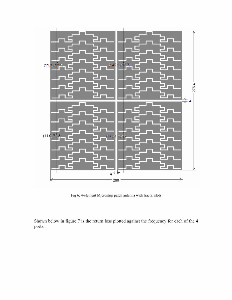
Fig 6: 4-element Microstrip patch antenna with fractal slots Shown below in figure 7 is the return loss plotted against the frequency for each of the 4 ports.

Fig 7: Return Loss vs. Frequency The Gain vs. θ is plotted below in figure 8:
Fig 8: Gain vs. θ (degrees)

The polarization pattern is plotted below:
Fig 9.1: E plane polarization plot, cross and coplanar Radiated Power Pattern:
Prad = 0.439mW
Figure 9.2 : Radiated Power Pattern

5.2 2-ELEMENT ARRAY: A 2-element array is again designed in a similar way. Each of the elements is fed with a power 1/2nd of the magnitude to obtain the superimposed radiation characteristics. This technique is a compromise between the achieved Gain and Size reduction (66%). The antenna structure is shown below:
Fig 10: 4-element Microstrip patch antenna with fractal slots
Shown below in figure 11 is the return loss plotted against the frequency for each of the 2 ports.
Fig 11: Return Loss vs. Frequency

The Gain vs. θ is plotted below in figure 12:
Fig 12: Gain vs. θ (degrees)
The polarization pattern is plotted below:
Fig 13.1: E plane polarization plot, cross and coplanar

Radiated Power Pattern:
Prad = 0.253mW
Fig 13.2: Radiated Power Pattern
6. FABRICATION AND TESTING: The designed antenna structure is fabricated and tested in the lab and the practical results are found to be well consistent with the simulated ones. Shown in figure below is the fabricated antenna structure.
Fig 14: Conducting strip of the antenna structure showing the feed point, ground plane conductor.

Shown below is the return loss plotted against frequency.
Fig 15: Return Loss plotted against frequency The radiation patterns are plotted below:
Fig 16: Power pattern - coplanar and cross

COMPARISON OF RESULTS:
Table 2: Comparison of Results Due to the errors in the fabrication process, the resonant frequency obtained practically is different from the simulated one. CONCLUSION Here a new fractal shaped defected microstrip antenna proposed in [1] is implemented. Using these defects, the surface current path is lengthened and thus the resonance frequency is decreased to a great level. When compared with an antenna of the same resonance frequency, a reduction of about 84 % is achieved in antenna size. Gain is enhanced to a great extent by making the 4-element array pattern of the single structure designed with the size reduction falling down to 33 %. A compromised design of a 2-element array pattern of the single structure gives considerable gain as well as 66 % size reduction. The designed structure of the single slotted patch is fabricated and tested for consistency of results. This work is thus a motivation towards applications where the overall volume of the structure is an important factor, such as mobile terminals, etc.
Performance Metrics
Simple Patch
antenna (unslotted)
Single fractal slotted patch (Simulated)
Single fractal slotted patch
(Practical)
4- element array
2-element array
Resonant frequency, fR (MHz)
441 454.0 493.1 455.5 444.5
Return Loss (dB)
-36.66 -16.73 -11.02 -18.27 -16.68
Gain at θ=0o(dB)
9.629 2.73 - 9.57 4.534
Size Reduction (% of simple patch)
0 84 84 33 66

REFERENCES: [1] A. Kordzadeh and F. Hojat Kashani, “A New Reduced Size Microstrip Patch Antenna with Fractal Shaped Defects,” Progress In Electromagnetics Research B, Vol. 11, 29–37, 2009 [2] Lo, T. K. and Y. Hwang, “Microstrip antennas of very high Permittivity for personal communications,” 1997 Asia Pacific Microwave Conference, 253–256, 1997. [3] Sinati, R. A., CAD of Microstrip Antennas for Wireless Applications, Artech House, Norwood, MA, 1996. [4] Wang, H. Y. and M. J. Lancaster, “Aperture-coupled thin film superconducting meander antennas,” IEEE Transaction on Antennas and Propagation, Vol. 47, 829–836, 1999. [5] Waterhouse, R., Printed Antennas for Wireless Communications, John Wiley & Sons Inc, 2007.

Appendix: Design of Microstrip patch antenna: Step 1: Calculation of the Width (W ): The width of the Microstrip patch antenna is given by
Step 2: Calculation of Effective dielectric constant (ε reff ):
Step 3: Calculation of the Effective length (L eff ):
Step 4: Calculation of the length extension ( ∆L):
Step 5: Calculation of actual length of patch ( L ):
Step 6: Calculation of the ground plane dimensions ( Lg and Wg ):