performance analysis of corporate feed rectangular patch element and circular patch element 4x2...
TRANSCRIPT

8/6/2019 Performance Analysis of Corporate Feed Rectangular Patch Element and Circular Patch Element 4x2 Micro Strip Arr…
http://slidepdf.com/reader/full/performance-analysis-of-corporate-feed-rectangular-patch-element-and-circular 1/6
(IJACSA) International Journal of Advanced Computer Science and Applications,
Vol. 2, No. 7, 2011
74 | P a g e www.ijacsa.thesai.org
Performance Analysis of Corporate Feed Rectangular
Patch Element and Circular Patch Element 4x2
Microstrip Array Antennas
Md. Tanvir Ishtaique-ul Huque.1, Md. Al-Amin Chowdhury 2, Md. Kamal Hosain3 , Md. Shah Alam4 1,2,3
Dept. of Electronics and Telecommunication Engineering,4
Dept. of Electrical and Electronic Engineering,
Rajshahi University of Engineering & Technology, Rajshahi-6204, Bangladesh.
Abstract — This paper present simple, slim, low cost and highgain circular patch and rectangular patch microstrip arrayantenna, with the details steps of design process, operate in X-band(8 GHz to 12 GHz) and it provides a mean to choose theeffective one based on the performance analysis of both of thesearray antennas. The method of analysis, design and developmentof these array antennas are explained completely here andanalyses are carried out for 4x2 arrays. The simulation has beenperformed by using commercially available antenna simulator,
SONNET version V12.56, to compute the current distribution,return loss response and radiation pattern. The proposedantennas are designed by using Taconic TLY-5 dielectricsubstrate with permittivity, εr = 2.2 and height, h =1.588 mm. Inall cases we get return losses in the range -4.96 dB to -25.21 dB atfrequencies around 10 GHz. The gain of these antennas as
simulated are found above 6 dB and side lobe label is maintainedlower than main lobe. Operating frequency of these antennas is10 GHz so these antennas are suitable for X-band application.
Keywords- microstrip array antenna; rectangular patch; return
loss; X band; circular patch.
I. INTRODUCTION
The term “Microstrip” comes because the thickness of thismetallic strip is in micro-meter range. Microstrip patchantennas are popular, because they have some advantages dueto their conformal and simple planar structure. They allow allthe advantages of printed-circuit technology. A vast number of papers are available on the investigation of various aspects of microstrip antennas [1, 5, 6, 7, 8, 12, 13]. The key features of amicrostrip antenna are relative ease of construction, lightweight, low cost and either conformability to the mountingsurface or, at least, an extremely thin protrusion from thesurface. These criteria make it popular in the field of satellite
and radar communication system. Different Radar systemssuch as synthetic aperture radar (SAR), remote sensing radars,shuttle imaging radar and other wireless communicationsystems operate in L, Ku, C and X bands [11, 12, 14, 15].Microstrip antennas are the first choice for this high frequencyband such as X-band due to its light weight, low cost, androbustness. In this paper the designed microstrip antennas arealso best suited for X band applications. The extended AM
broadcast band or simply “X band” is a segment of themicrowave radio region of the electromagnetic spectrum. X-band radar frequency sub-bands are used in civil, military andgovernment institutions for weather monitoring, air trafficcontrol, maritime vessel traffic control, defense tracking, and
vehicle speed detection for law enforcement. In radarengineering, its frequency range is specified by the IEEE at8.0 to 12.0 GHz. X band is used in radar applicationsincluding continuous-wave, pulsed, single-polarization, dual-polarization, synthetic aperture radar, and phased arrays. InIreland, Libya, Saudi Arabia and Canada, the X band 10.15 to10.7 segment is used for terrestrial broadband. Portions of theX band are assigned by the International TelecommunicationsUnion (ITU) exclusively for deep space telecommunications.The primary user of this allocation is the American NASADeep Space Network (DSN) [16].
Microstrip patch elements are available in variousconfiguration. But the most common is the rectangular patchelement and after the rectangular patch element the next most
well known configuration is the circular patch element. Thispaper presents the design procedure, characteristic and thecorresponding performance analysis of both the rectangularand circular patch microstrip array antennas and provides amean to choose the effective one based on their performanceparameters to get the efficient radiation efficiency. In thispaper we have also investigated the performance of corporatefeed array in case of both the rectangular patch element andcircular patch element, because it provides better directivity aswell as radiation efficiency and reduce the beam fluctuationsover a band of frequencies compared to the series feed array[5, 9]. Here all of these antennas are designed to support 10GHz operating frequency and their corresponding simulationshave been done by using the SONNET version V12.56
simulator. The proposed antennas are designed by usingTaconic TLY-5 dielectric substrate with permittivity, εr = 2.2and height, h =1.588 mm. These designed antennas arepromising to be a good candidate for the X-band wirelessapplications due to the simplicity in structure, ease of fabrication and high gain and high efficiency.
II. MICROSTRIP ANTENNA DESIGN
Microstrip patch antennas consist of very thin metallicstrip (patch) placed on ground plane where the thickness of the

8/6/2019 Performance Analysis of Corporate Feed Rectangular Patch Element and Circular Patch Element 4x2 Micro Strip Arr…
http://slidepdf.com/reader/full/performance-analysis-of-corporate-feed-rectangular-patch-element-and-circular 2/6
(IJACSA) International Journal of Advanced Computer Science and Applications,
Vol. 2, No. 7, 2011
75 | P a g e www.ijacsa.thesai.org
metallic strip is restricted by t<< λ 0 and the height is restricted by 0.0003λ 0 ≤ h ≤ .05λ 0 [2, 5]. The microstrip patch isdesigned so that its radiation pattern maximum is normal tothe patch. For a rectangular patch, the length L of the elementis usually λ 0 /3 <L< λ 0 /2. There are numerous substrates thatcan be used for the design of microstrip antennas and theirdielectric constants are usually in the range of 2.2 ≤ εr ≤12. Toimplement the microstrip antennas usually Fr-4 (εr = 4.9),Rogers TMM 4(εr = 4.5), Taconic TLY-5 (εr = 2.2), Alumina(96%) (εr = 9.4), Teflon(PTFE) (εr = 2.08), Arlon AD 5 (εr =5.1) dielectric materials are used as the substrate [1, 2, 5, 10].
The Performance of the microstrip antenna depends on itsdimension. Depending on the dimension the operatingfrequency, radiation efficiency, directivity, return loss andother related parameters are also influenced [3]. Here, in thispaper, the investigation is made on two types of microstrippatch elements. They are
Rectangular patch element
Circular patch element.
A. Rectangular Patch Element
For an efficient radiation a practical width of theRectangular patch element becomes [2, 3, 5]
1
2
2
1
r r f w
And the length of the antenna becomes [2, 3, 5]
(2)
Where,
8.0
264.0
258.0
3.041.0
h
w
h
w
h L eff
eff
And
w
h
r r eff
1212
1
2
1
Where, λ is the wave length, ƒr (in Hz) is the resonant
frequency, L and W are the length and width of the patch
element, in cm, respectively andr
is the relative dielectric
constant. In the following Fig. 1, the antenna has beendesigned to cover specific 10 GHz operating frequency wherethe antenna dimension is in mm range and the quarter
wavelength transformer method [2, 5] is used to match theimpedance of the patch element with the transmission line.
Figure 1. Single element Rectangular microstrip patch antenna.
B. Circular Patch Element
Other than the rectangular patch, the next most popularconfiguration is the circular patch or disk. For rectangularpatch elements there are two degrees of freedom to controlwhereas for the circular patch elements there is one degree of freedom to control. Thus it is more convenient to design aswell as to control the radiation pattern of the circular patchelement.
From [12, 14] the first order approximation of the physicalradius of the circular patch element becomes.
Where
Thus the effective area of the circular patch element isgiven by [12]
(6)
Where, r f (in Hz) is the resonant frequency, h(in cm) is
the thickness of the substrate, ɑ is the effective radius of the
circular patch element and r is the relative dielectric
constant.
In the following Fig. 2, the antenna has been designed tocover specific 10 GHz operating frequency where the antennadimension is in mm range and the quarter wavelengthtransformer method [2, 5] is used to match the impedance of the patch element with the transmission line.
Figure 2. Single element circular microstrip patch antenna.
III. MICROSTRIP ARRAY ANTENNA DESIGN
Microstrip antennas are used not only as single element butalso very popular in arrays. Microstrip arrays radiate
efficiently only over a narrow band of frequencies and theycan’t operate at the high power levels of waveguide, coaxialline, or even stripline [1]. Antenna arrays are used to scan thebeam of an antenna system, to increase the directivity andperform various other functions which would be difficult withany one single element. In the microstrip array, elements canbe fed by a single line or by multiple lines in a feed network arrangement. Based on their feeding method [2, 5] the array isclassified as
Series feed network
)1(
L
eff r f
L 2
002
1
)3(
)4(
]}7726.1)2
[ln(2
1{
h
F
F r
h
F a
)5(
r r f F
910791.8
]}7726.1)
2
[ln(2
1{2
h
F
F r
ha
eff
A

8/6/2019 Performance Analysis of Corporate Feed Rectangular Patch Element and Circular Patch Element 4x2 Micro Strip Arr…
http://slidepdf.com/reader/full/performance-analysis-of-corporate-feed-rectangular-patch-element-and-circular 3/6
(IJACSA) International Journal of Advanced Computer Science and Applications,
Vol. 2, No. 7, 2011
76 | P a g e www.ijacsa.thesai.org
Corporate feed network
Series-feed microstrip array is formed by interconnectingall the elements with high impedance transmission line andfeeding the power at the first element. Because the feedarrangement is compact the line losses associated with thistype of array are lower than those of the corporate-feed type[5]. The main limitation in series-feed arrays is the largevariation of the impedance and beam-pointing direction over a
band of frequencies [5].
The corporate-feed network is used to provide power splitsof 2n (i.e. n = 2; 4; 8; 16; etc.). This is accomplished by usingeither tapered lines or using quarter wavelength impedancetransformers [5, 6]. In this paper the patch elements areconnected by using the quarter wavelength impedancetransformer method.
Corporate-feed arrays are general and versatile. Thismethod has more control of the feed of each element and isideal for scanning phased arrays, multiband arrays. Thus itprovides better directivity as well as radiation efficiency andreduce the beam fluctuations over a band of frequenciescompared to the series feed array [5, 9]. The phase of eachelement can be controlled by using phase shifters whileamplitude can be adjusted using either amplifiers orattenuators [2, 8].
In this paper we have investigated the performance of corporate feed array in case of both the rectangular patchelement and circular patch element.
A. Rectangular Patch Microstrip Array
In this paper we have designed the 8-elements rectangularpatch Microstrip array antenna, as shown in Fig. 3, to cover 10GHz operating frequency. Here the power is fed to the antennaby using the Microstrip transmission line method[2, 3] and thepatch elements are matched together as well as with the
transmission line with the quarter wavelength transformermethod for the maximum power transmission.
The radiated field of the E -plane for a single elementrectangular patch can be expressed by using the followingformula [2, 10].
(7)
Here, W is the width of the patch antenna, Le is theextended length, V0 =hE0 is the voltage across radiating slot of the patch, h is the substrate height, K0 =2π/λ and r is the farfield distance from the antenna.
The array factor as given in [4, 8] as
(8)
Here, dx is the element spacing and N is the number of
elements. Combining array factor and element voltage
radiation pattern we get the total element normalized powerradiation pattern [2, 4, 5] that is
Figure 3. 8-elements corporate-feed rectangular microstrip array antenna.
B. Circular Patch Microstrip Array
Here the 8-elements circular patch Microstrip arrayantenna, as shown in Fig. 4, is designed to operate at 10 GHzfrequency and similar to the previous one the power is fed tothe antenna by using the Microstrip transmission line methodand the patch elements are matched together as well as withthe transmission line with the quarter wavelength transformermethod for the maximum power transmission.
Figure 4. 8-elements corporate-feed circular microstrip array antenna.
The radiated field of the E -plane for a single elementcircular patch can be expressed by using the following formula
[2, 5].
(10)
Here, θ is the beam pointing angle measured from thebroadside direction, V0 =hE0 is the voltage across radiatingslot of the patch, K0 =2π/λ , J1 is the Bessel function of firstorder and r is the far field distance from the antenna. The arrayfactor as given in [14] as
(11)
Where
Here, α is the phase difference between elements, N is thenumber of array elements and S is the spacing betweencircular patch elements. Now we can get the normalized powerradiation pattern by combining the element radiation patternand array factor [5].
)sin2
cos(}
cos2
)cos2
sin(
{ 0
0
0
000
e
r jk Lk
hk
hk
r
eWV k j E
)sin) / ((sin
)sin) / ((sin22
2
x
x
d N
d N FA
) / log(20 FA E )9(
)2
sin(
)2
sin(
0
N
N
A AF
)cos()sin( d
Sd )2
(
)sin(cos2
0
'
1
0
0
0
ak J r
eak jV E
r jk
8/6/2019 Performance Analysis of Corporate Feed Rectangular Patch Element and Circular Patch Element 4x2 Micro Strip Arr…
http://slidepdf.com/reader/full/performance-analysis-of-corporate-feed-rectangular-patch-element-and-circular 4/6
(IJACSA) International Journal of Advanced Computer Science and Applications,
Vol. 2, No. 7, 2011
77 | P a g e www.ijacsa.thesai.org
IV. SIMULATION RESULT & DISCUSSION
A. Rectangular Microstrip Array Antenna Parameters
Figure 5. Current distribution of 8-elements rectangular microstrip array
antenna.
In this paper, it is considered that the substrate permittivityof the antenna is εr = 2.2 (Taconic TLY-5), height is 1.588mm and resonance frequency of the antenna is 10 GHz. Aftersimulation, as shown in Fig. 6, we found that, return loss is -25.21 dB at 10 GHz and it is maximum.
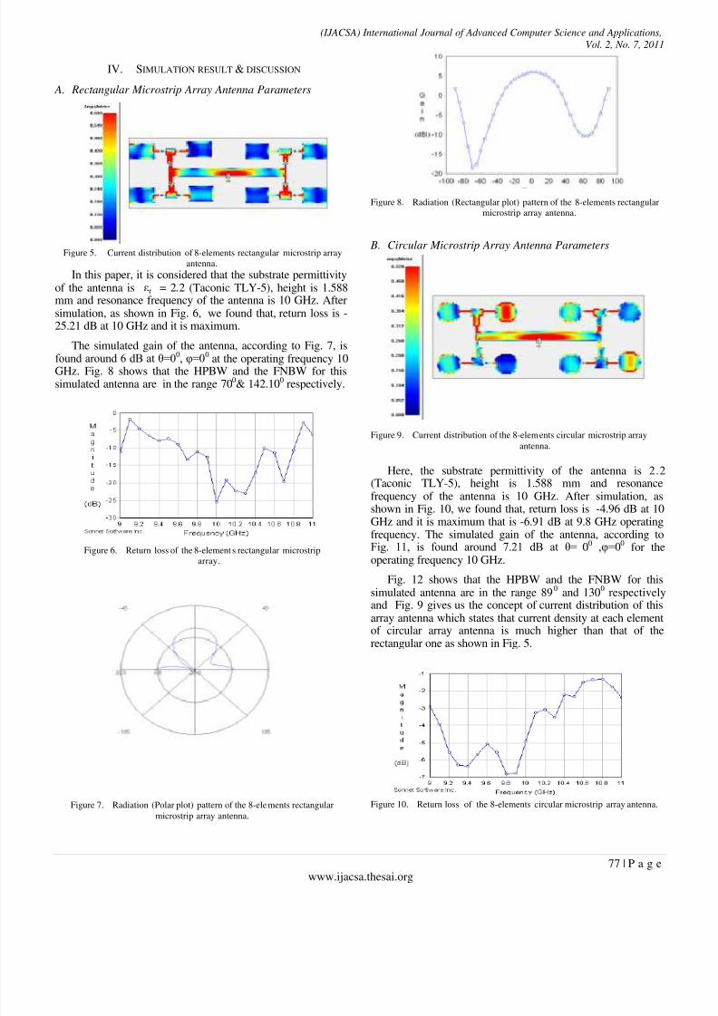
The simulated gain of the antenna, according to Fig. 7, is
found around 6 dB at θ=00, φ=00 at the operating frequency 10GHz. Fig. 8 shows that the HPBW and the FNBW for thissimulated antenna are in the range 70
0& 142.10
0respectively.
Figure 6. Return loss of the 8-elements rectangular microstrip
array.
Figure 7. Radiation (Polar plot) pattern of the 8-elements rectangular
microstrip array antenna.
Figure 8. Radiation (Rectangular plot) pattern of the 8-elements rectangular
microstrip array antenna.
B. Circular Microstrip Array Antenna Parameters
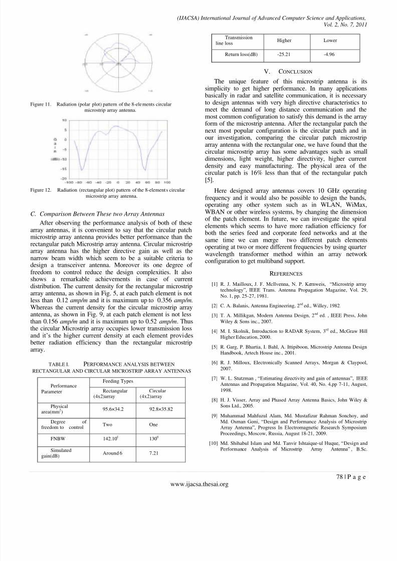
Figure 9. Current distribution of the 8-elements circular microstrip array
antenna.
Here, the substrate permittivity of the antenna is 2.2(Taconic TLY-5), height is 1.588 mm and resonancefrequency of the antenna is 10 GHz. After simulation, asshown in Fig. 10, we found that, return loss is -4.96 dB at 10GHz and it is maximum that is -6.91 dB at 9.8 GHz operating
frequency. The simulated gain of the antenna, according toFig. 11, is found around 7.21 dB at θ=
00 ,φ=00
for theoperating frequency 10 GHz.
Fig. 12 shows that the HPBW and the FNBW for thissimulated antenna are in the range 89
0and 130
0respectively
and Fig. 9 gives us the concept of current distribution of thisarray antenna which states that current density at each elementof circular array antenna is much higher than that of therectangular one as shown in Fig. 5.
Figure 10. Return loss of the 8-elements circular microstrip array antenna.
8/6/2019 Performance Analysis of Corporate Feed Rectangular Patch Element and Circular Patch Element 4x2 Micro Strip Arr…
http://slidepdf.com/reader/full/performance-analysis-of-corporate-feed-rectangular-patch-element-and-circular 5/6
(IJACSA) International Journal of Advanced Computer Science and Applications,
Vol. 2, No. 7, 2011
78 | P a g e www.ijacsa.thesai.org
Figure 11. Radiation (polar plot) pattern of the 8-elements circular
microstrip array antenna.
Figure 12. Radiation (rectangular plot) pattern of the 8-elements circular
microstrip array antenna.
C. Comparison Between These two Array Antennas
After observing the performance analysis of both of thesearray antennas, it is convenient to say that the circular patchmicrostrip array antenna provides better performance than therectangular patch Microstrip array antenna. Circular microstriparray antenna has the higher directive gain as well as thenarrow beam width which seem to be a suitable criteria todesign a transceiver antenna. Moreover its one degree of freedom to control reduce the design complexities. It alsoshows a remarkable achievements in case of currentdistribution. The current density for the rectangular microstrip
array antenna, as shown in Fig. 5, at each patch element is notless than 0.12 amp/m and it is maximum up to 0.356 amp/m.Whereas the current density for the circular microstrip arrayantenna, as shown in Fig. 9, at each patch element is not lessthan 0.156 amp/m and it is maximum up to 0.52 amp/m. Thusthe circular Microstrip array occupies lower transmission lossand it’s the higher current density at each element providesbetter radiation efficiency than the rectangular microstriparray.
TABLE I. PERFORMANCE ANALYSIS BETWEEN
RECTANGULAR AND CIRCULAR MICROSTRIP ARRAY ANTENNAS
Performance
Parameter
Feeding Types
Rectangular(4x2)array Circular(4x2)array
Physicalarea(mm2)
95.6×34.2 92.8×35.82
Degree of freedom to control
Two One
FNBW 142.100 1300
Simulatedgain(dB)
Around 6 7.21
Transmissionline loss
Higher Lower
Return loss(dB) -25.21 -4.96
V. CONCLUSION
The unique feature of this microstrip antenna is itssimplicity to get higher performance. In many applications
basically in radar and satellite communication, it is necessaryto design antennas with very high directive characteristics tomeet the demand of long distance communication and themost common configuration to satisfy this demand is the arrayform of the microstrip antenna. After the rectangular patch thenext most popular configuration is the circular patch and inour investigation, comparing the circular patch microstriparray antenna with the rectangular one, we have found that thecircular microstrip array has some advantages such as smalldimensions, light weight, higher directivity, higher currentdensity and easy manufacturing. The physical area of thecircular patch is 16% less than that of the rectangular patch[5].
Here designed array antennas covers 10 GHz operating
frequency and it would also be possible to design the bands,operating any other system such as in WLAN, WiMax,WBAN or other wireless systems, by changing the dimensionof the patch element. In future, we can investigate the spiralelements which seems to have more radiation efficiency forboth the series feed and corporate feed networks and at thesame time we can merge two different patch elementsoperating at two or more different frequencies by using quarterwavelength transformer method within an array network configuration to get multiband support.
REFERENCES
[1] R. J. Mailloux, J. F. Mcllvenna, N. P. Kernweis, “Microstrip arraytechnology”, IEEE Trans. Antenna Propagation Magazine, Vol. 29,
No. 1, pp. 25-27, 1981.
[2] C. A. Balanis, Antenna Engineering, 2nd ed., Willey, 1982.
[3] T. A. Millikgan, Modern Antenna Design, 2nd ed. , IEEE Press, John
Wiley & Sons inc., 2007.
[4] M. I. Skolnik, Introduction to RADAR System, 3rd ed., McGraw Hill
Higher Education, 2000.
[5] R. Garg, P. Bhartia, I. Bahl, A. Ittipiboon, Microstrip Antenna Design
Handbook, Artech House inc., 2001.
[6] R. J. Milloux, Electronically Scanned Arrays, Morgan & Claypool,
2007.
[7] W. L. Stutzman , “Estimating directivity and gain of antennas”, IEEE
Antennas and Propagation Magazine, Vol. 40, No. 4,pp 7-11, August,
1998.
[8] H. J. Visser, Array and Phased Array Antenna Basics, John Wiley &
Sons Ltd., 2005.
[9] Muhammad Mahfuzul Alam, Md. Mustafizur Rahman Sonchoy, and
Md. Osman Goni, “Design and Performance Analysis of MicrostripArray Antenna”, Progress In Electromagnetic Research Symposium
Proceedings, Moscow, Russia, August 18-21, 2009.
[10] Md. Shihabul Islam and Md. Tanvir Ishtaique-ul Huque, “Design and
Performance Analysis of Microstrip Array Antenna” , B.Sc.

8/6/2019 Performance Analysis of Corporate Feed Rectangular Patch Element and Circular Patch Element 4x2 Micro Strip Arr…
http://slidepdf.com/reader/full/performance-analysis-of-corporate-feed-rectangular-patch-element-and-circular 6/6
(IJACSA) International Journal of Advanced Computer Science and Applications,
Vol. 2, No. 7, 2011
79 | P a g e www.ijacsa.thesai.org
Engineering thesis, Dept. of ETE, Rajshahi University Of Engineering
& Technology(RUET), Rajshahi, Bangladesh, April, 2010.
[11] Gi-cho Kang, Hak-young Lee, Jong-kyu Kim, Myun-joo Park ,”Ku-
band High Efficiency Antenna with Corporate-Series-Fed Microstrip
Array”, IEEE Antennas and Propagation Society International
Symposium, 2003 .
[12] T. F. Lai, Wan Nor Liza Mahadi, Norhayatision, “Circular Patch
Microstrip Array Antenna for KU- band”, World Academy of Science,
Engineering and Technology, vol. 48, pp. 298-302, 2008.
[13] K. Shambavi, C. Z. Alex , T. N. P. Krishna, “ Design and Analysis of
High Gain Milimeter Wave Microstrip Antenna Array for Analysis of
High Gain Millimeter Wave Microstrip Anteanna Array for Wireless
Application”, Journal of Applied Theoretical and Information
Technology(JATIT), 2009.
[14] Asghar Keshtkar, Ahmed Keshtkar and A. R. Dastkhosh, “Circular Microstrip Patch Array Antenna for C-Band Altimeter System”,
International Journal of Antenna and Propagation, article ID 389418,
doi:10.1155/2008/389418, November, 2007.
[15] M. F. Islam, M. A. Mohd. Ali, B. Y. Majlis and N. Misran, “Dual
Band Microstrip Patch Antenna for Sar Applications”, Australian
Journal of Basic and Applied Sciences, 4(10): 4585- 4591, 2010.
[16] http://en.wikipedia.org/wiki/X_band
AUTHORS PROFILE
Md. Tanvir Ishtaique-ul Huque was born in 1988 in Bangladesh. He
received his B.Sc. Engineering degree from the Rajshahi University of
Engineering & Technology (RUET) in 2010. Now he is working as a part time
teacher in the Dept. of Electronics and Telecommunication Engineering of
RUET. His research interests include the antenna application of the wireless
body area network(WBAN) and next generation wireless communication
system.
Md. Al-Amin Chowdhury was born in 1988 in Bangladesh. he has
completed his B.Sc. in Electronic and Telecommunicaton Engineering from
Rajshahi University of Engineering & Technology(RUET) in 2010. He has
keen interest to research on the optical fiber, different types of antennas. He
wants to do his further study in USA on the communication field. World is
becoming closer and closer due to the remarkable achievements in the
communication field. He wants to receive the sound and proper knowledge in
communication field so that he can contribute to the next generation
demands in the communication sectors.
Md. kamal Hosain was born in 1982 in Bangladesh. He received his B.Sc.
Engineering degree from the khulna University of Engineering &
Technology(KUET) in 2001 and now he working as a Lecturer in the Dept. of
Electronics and Telecommunication Engineering(ETE) of RUET. His research
interests include the antenna and its application on the biomedical devices.
Md. Shah Alam was born in Rangpur, Bangladesh, on June 24, 1982. He
received the B.Sc. degree in Electrical and Electronic Engineering from
Rajshahi University of Engineering & Technology, Rajshahi, Bangladesh, in
2006. He is going to be completed his M.SC degree from the same institution
on July, 2011. From 2007 to 2009, he was a Lecturer with the Rajshahi
University of Engineering & Technology, Rajshahi, Bangladesh and currently
he is working there as an Assistant Professor. His research interests involveElectromagnetic and Nanotechnology.