sitrans f m magflo - lesman€¦ · sitrans f m magflo ® electromagnetic ... • siemens flow...
TRANSCRIPT
Order no.: FDK-521H1191
SFIDK.PS.026.E8.02
SITRANS F M MAGFLO®®®®®
Electromagnetic flowmetersTransmitter type MAG 6000 Industry & MAG 6000 Industry (Ex d)sensor type MAG 1100/MAG 1100 FOOD/MAG 1100 Ex/MAG 1100 FOOD Ex & MAG 5100 W/MAG 3100/MAG 3100 Ex
[ ]
*083R9176*
Operating ManualEdition 10/2006 - Revision 08
s
Technical Documentation (handbooks, instructions, manuals etc.) on the complete productrange SITRANS F can be found on the internet/intranet on the following links:
English: http://www4.ad.siemens.de/WW/view/en/10806951/133300

SITRANS F M MAGFLO®®®®®
2 SFIDK.PS.026.E8.02
EN
GL
ISH Contents 1. Introduction ................................................................................................................... 3
2. Installation ..................................................................................................................... 42.1 Installation of transmitter ............................................................................................... 42.2 Installation of sensor ..................................................................................................... 42.3.1 Remote installation - At the sensor ............................................................................... 62.3.2 Remote installation - Transmitter .................................................................................. 62.4 Ex survey according to Directive 94/9/EC (ATEX) ........................................................ 72.5 Overview and intrinsically safe data ............................................................................. 82.5.1 Transmitter data MAG 6000 I (Ex d) .............................................................................. 82.6 Device identification ..................................................................................................... 92.7 Ex approvals ............................................................................................................... 10
3. Electrical connection ................................................................................................... 123.1 Transmitter type MAG 6000 I ...................................................................................... 113.2 Installation examples .................................................................................................. 133.2.1 Add-on communication module ................................................................................. 14
4. Technical data ............................................................................................................. 154.1.1 Dimensions and weight .............................................................................................. 154.1.1.1 MAG 1100 standard & Ex ........................................................................................... 154.1.1.2 MAG 1100 FOOD standard & Ex ................................................................................ 164.1.2 Sensor MAG 1100 Ex & MAG 1100 FOOD Ex ............................................................ 174.2.1 Dimensions and weight MAG 3100 Ex ....................................................................... 184.2.2 Sensor MAG 3100 Ex ................................................................................................. 204.2.3 Dimensions and weight MAG 5100 W........................................................................ 214.2.4 Sensor MAG 5100 W .................................................................................................. 234.3 Transmitter type MAG 6000 I ....................................................................................... 244.4 Output characteristics MAG 6000 I ............................................................................. 25
5. Commissioning ........................................................................................................... 265.1 Keypad and display layout ......................................................................................... 265.2 Menu build-up ............................................................................................................. 275.2.1 Password .................................................................................................................... 275.3 MAG 6000 I ................................................................................................................. 285.4 Basic settings .............................................................................................................. 295.4.1 Outputs ........................................................................................................................ 305.4.2 Digital and relay outputs ............................................................................................. 315.4.3 Relay outputs .............................................................................................................. 315.4.4 External input .............................................................................................................. 315.4.5 Sensor characteristics ................................................................................................ 325.4.6 Reset mode ................................................................................................................. 325.4.7 Service mode .............................................................................................................. 335.4.8 Operator menu setup .................................................................................................. 345.4.9 Product identity ........................................................................................................... 355.4.10 Change password ...................................................................................................... 355.4.11 Language mode ......................................................................................................... 365.4.12 HART® communication .............................................................................................. 365.5 Settings available ....................................................................................................... 365.5.1 Dimension dependent factory settings ....................................................................... 395.5.2 Dimension dependent batch and pulse output settings ............................................. 395.6.1 Totalizer ....................................................................................................................... 395.6.2 Batch ........................................................................................................................... 395.6 Flow rate ..................................................................................................................... 395.6.3 List of error numbers ................................................................................................... 416. Service ........................................................................................................................ 416.1 Transmitter check list ................................................................................................... 416.2 Trouble shooting MAG transmitter .............................................................................. 426.3 Check list MAG sensor ................................................................................................ 436.4 Coil resistance ............................................................................................................ 45
7. Ordering ...................................................................................................................... 44
8. Certificates .................................................................................................................. 458.1 EC-declaration of conformity ...................................................................................... 458.2 EC type examination certificate .................................................................................. 46

SITRANS F M MAGFLO®®®®®
3SFIDK.PS.026.E8.02
EN
GL
ISH1. Introduction For safety reasons it is important that the following points, especially the points marked with a
warning sign, are read and understood before the system is being installed:
• Installation, connection, commissioning and service must be carried out by personnelwho are qualified and authorized to do so.
• It is very important that the same people have read and understand the instructions anddirections provided in this manual and that they follow the instructions and directionsbefore taking the equipment into use!
• People who are authorized and trained by the owner of the equipment may operate theequipment.
• The installation must ensure that the measuring system is correctly connected and is inaccordance with the connection diagram.
• In applications with working pressures/media that can be dangerous to people, surroundings,equipment or others in case of pipe fracture, we recommend that special precautions suchas special placement, shielding or installation of a security guard or a security valve shouldbe made when the sensor is being installed.
• Siemens Flow Instruments want to assist by estimating the chemical resistance of the sensorparts that are in connection with the media, but it is at any time the customer’s responsibility,which materials are chosen and Siemens Flow Instruments takes no responsibility if thesensor corrodes!
• Equipment used in hazardous areas must be Ex-approved and marked for Europe, FMfor USA and CSA for Canada.It is required that the special directions provided in the manual and in the Ex certificate mustbe followed!
• Installation of the equipment must comply with national regulations.Example EN 60079-14 for Denmark.
• Repair and service must be done by approved Siemens Flow Instruments personnel only.
1. Introduction

SITRANS F M MAGFLO®®®®®
4 SFIDK.PS.026.E8.02
EN
GL
ISH 2. Installation
2. Installation
Category 2 equipmentIn addition to the sensor, the MAG 6000 I asremote or compact mounted may be installed inEx zone 1 and zone 2.
2.2 Installation of sensor
Installation of transmitter can be remote orcompact mounted.
2.1 Installation oftransmitter
Hazardous area
The sensor must always be completely full withliquid.
Therefore avoid:• Installation at the highest point in the pipe
system• Installation in vertical pipes with free outlet
For partially filled pipes or pipes with down-ward flow and free outlet the flowmeter shouldbe located in a U-tube.
Installation in vertical pipesRecommended flow direction: upwards. Thisminimizes the effect on the measurement ofany gas/air bubbles in the liquid.
SITRANS F M MAGFLO®®®®®
5SFIDK.PS.026.E8.02
EN
GL
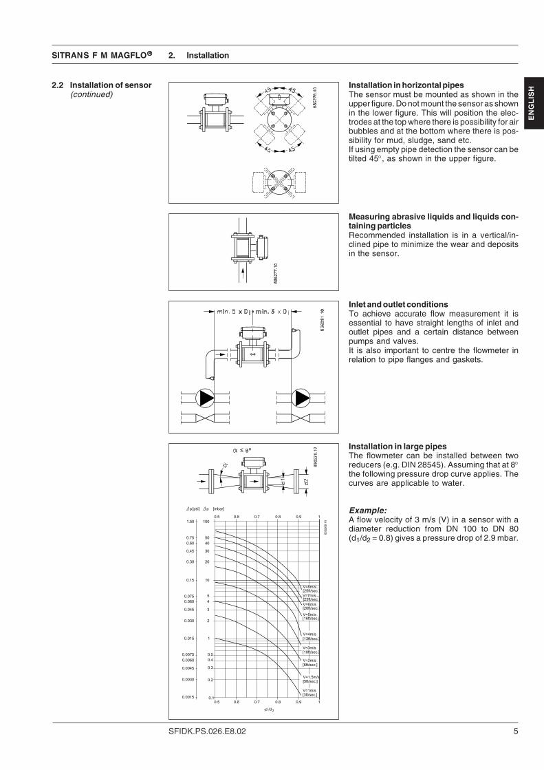
ISHInstallation in horizontal pipes
The sensor must be mounted as shown in theupper figure. Do not mount the sensor as shownin the lower figure. This will position the elec-trodes at the top where there is possibility for airbubbles and at the bottom where there is pos-sibility for mud, sludge, sand etc.If using empty pipe detection the sensor can betilted 45°, as shown in the upper figure.
Measuring abrasive liquids and liquids con-taining particlesRecommended installation is in a vertical/in-clined pipe to minimize the wear and depositsin the sensor.
Inlet and outlet conditionsTo achieve accurate flow measurement it isessential to have straight lengths of inlet andoutlet pipes and a certain distance betweenpumps and valves.It is also important to centre the flowmeter inrelation to pipe flanges and gaskets.
2.2 Installation of sensor(continued)
Installation in large pipesThe flowmeter can be installed between tworeducers (e.g. DIN 28545). Assuming that at 8°the following pressure drop curve applies. Thecurves are applicable to water.
Example:A flow velocity of 3 m/s (V) in a sensor with adiameter reduction from DN 100 to DN 80(d1/d2 = 0.8) gives a pressure drop of 2.9 mbar.
2. Installation

SITRANS F M MAGFLO®®®®®
6 SFIDK.PS.026.E8.02
EN
GL
ISH 2.3.1 Remote installation -
At the sensor
Fit and connect the electrode and coil cablesas shown in “Electrical connections”.The unscreened cable ends must be kept asshort as possible.The electrode cable and the coil cable must bekept separate to prevent interference.Tighten the cable glands well to obtain opti-mum sealing.
Remove the SENSORPROM® unit from thesensor and mount it in the terminal block in thetransmitter.
2.3.2 Remote installation -Transmitter
No power up with open lid -Do not open lid while poweron
Fit the SENSORPROM® memory unit in the transmitter.The SENSORPROM® unit is supplied with the sensor in the terminal box.
2. Installation

SITRANS F M MAGFLO®®®®®
7SFIDK.PS.026.E8.02
EN
GL
ISH2.4 Ex survey according
to Directive 94/9/EC(ATEX)
Applies to instruments used in underground miningoperations, as well as their above groundoperations, which can be endangered by mine gasand/or flammable dusts.
Instrument groups
Applies to instruments used in the remaining areaswhich can be endangered by a potentially explosiveatmosphere.
Instruments of this category are for use inareas where ignitable atmospheres, caused bya mixture of air and gasses, vapours or mists orby dust/air mixtures, can exist all of the time orfor long periods of time or else frequently.
Instruments of this category are for use inareas where ignitable atmospheres caused, bya mixture of air and gasses, vapours or mists orby dust/air mixtures, can exist some of the time.
Instruments of this category are for use inareas where ignitable atmospheres, caused bya mixture of air and gasses, vapours or mists orby dust/air mixtures, are not likely to exist.However, if they do occur then in all probability,only seldom or for short periods of time.
Instrument category
(The figures in brackets refer to IEC)
Built according to European norm = E
Explosion protected electrial equipment = ExEx protection labelling in square brackets refers to "Associated electrical equipment"
as an example: II 2G E Ex d IIB T3-T6
Type of protection
o Oil encapsulated i Intrinsic safety (ia, ib)p Pressurized apparatus n Non-incentive equipmentq Powder filling m Encapsulationd Flameproof enclosure s Special protectione Increased safety
Explosion groups
Gases and vapours Minimum EN/(examples) ignition IEC
energy [mJ]• Ammonia - IIA• Acetone, aircraft fuel, benzine,
crude oil, diesel oil, ethane, ethanoicacid, ether, gasolines, heating oil,hexane, methane, propane 0.18 IIA
• Ethylene, isoprene, town gas 0.06 IIB• Acetylene, carbon disulphide,
hydrogen 0.02 IIC
Ignition temperature
Maximum surface temperature EN / IEC450°C 842°F T1300°C 572°F T2200°C 392°F T3135°C 275°F T4100°C 212°F T5
85°C 185°F T6
I
IIE
N 5
0014
Dir
ecti
ve 9
4/9/
EC
(AT
EX
)
Definition
1G(0)
Labe
lling
wit
h g
ases
Labe
lling
with
dus
ts
1D(20)
2G(1)
2D(21)
3G(2)
3D(22)
2. Installation

SITRANS F M MAGFLO®®®®®
8 SFIDK.PS.026.E8.02
EN
GL
ISH 2.5 Overview and
intrinsically safe dataSpecifications:Supply: 115-230 V or 24 VAmbient temperature: −20 to 60°CEnclosure: IP67/NEMA 4X
2. Installation
SENSOR INTERFACE
1. DN 2 - DN 300 mmCertificate: Sira 03ATEX1503X II 2(1)(2) G D
Remote version: EEx d [ia] ia [ib] ib IIB T6 / Compact version: EEx d [ia] [ib] IIB T6
2.5.1 Transmitter dataMAG 6000 I (Ex d)
Electrode
81,82,83,84
IIB IIC
Uo 30 V 30 V
Io 6.1 mA 6.1 mA
Co 66 nF 560 nF
Lo 0.96 H 0.96 H
Po 45.5 mW 45.5 mW
! Coil terminal 85, 86 are “e” terminals.
2. DN 350 - 2000 mmCertificate: Sira 05ATEX2072X II 2(1)(2) G D
Remote version: EEx d e [ia] ia [ib] ib IIC T6 / Compact version: EEx d [ia] [ib] IIC T6
User I/O INTERFACE
DN 2 - DN 300Certificate: Sira 03ATEX1503X II 2(1)(2) G D
Remote version: EEx d [ia] ia [ib] ib IIB T6 / Compact version: EEx d [ia] [ib] IIB T6
DN 350 - DN 2000Certificate: Sira 05ATEX2072X II 2(1)(2) G D
Remote version: EEx d e [ia] ia [ib] ib IIC T6 / Compact version: EEx d [ia] [ib] IIC T6
Electrode Coil
81,82,83,84 85,86
IIB IIC* IIB IIC*
Uo 30 V Uo 30 V
Io 6.1 mA Io 105 mA
Co 560 nF Co 60 nF
Lo 1 H Lo 2.07 mH
Po 45.5 mW Po 3.3 W
* N/A

SITRANS F M MAGFLO®®®®®
9SFIDK.PS.026.E8.02
EN
GL
ISHCurrent (31-32) Relay (44,45,46) Freq./pulse (56,57) Profi (95, 96) (FISCO) Dig. Input (77,78)
Passive IIB/IIC IIB/IIC IIB/IIC IIB/IIC IIB/IIC
Ui 30 V Ui 30 V Ui 28 V Ui 17.5 V Ui 30 V
Ii 100 mA Ii 200 mA Ii 100 mA Ii 380 mA Ii
Ci 16.5 nF Ci 0 Ci 12 nF Ci 0 Ci 0
Li 36 µH Li 0 Li 36 µH Li 0 Li 0
Pi 5.32 W Pi
Active IIB IIC
Uo 30 V 30 V
Io 87.8 mA 87.8 mA
Co 560 nF 66 nF
Lo 18.41 mH 4.57 mH
Po 0.66 W 0.66 W
2.6 Device identification
Example label, sensorremote MAG 3100 Ex
Category 2 equipmentSensors may be installed in zone 1 and zone 2.
Sensors intrinsically safe dataSee table below.
MAG 1100 & MAG 3100EEx ia IIB T3...T6
Terminals 85-86 82-83MAG sensor coil electrodeUi 28 V 30 VIi 140 mA 50 mAPi 2 W 0.5 WLi 2 mH 20 µHCi 50 nF 50 nF
MAG 1100 DN 2 - 100MAG 1100 FOOD DN 10 - 100MAG 3100 DN 15 - 300 Ex ib
Terminals 85-86 82-83MAG sensor coil electrodeUi -Ii - 50 mAPi - 0.5 WLi -Ci - 50 nF
MAG 3100 DN 350 - 2000 Ex e ia
IS data sensor
Terminals 85-86 82-83MAG sensors Coil circuit "ib" Electrode
circuit "ia"
Ui 30 V 30 VIi 140 mA 50 mAPi 2 W 0.5 WLi 2 mH 20 µHCi 50 nF 50 nF
All MAG 1100 Ex and MAG 3100 Ex sensorshave the following ratings and input parameters:
2. Installation

SITRANS F M MAGFLO®®®®®
10 SFIDK.PS.026.E8.02
EN
GL
ISH
Example label, transmittertype MAG 6000 I (Ex d)compact
2. Installation
Data not for reference
2.7 Ex approvals MAG 1100 Ex DN 2 - DN 100MAG 1100 FOOD Ex DN 10 - DN 100SIRA 03 ATEX 1423X CE 0518 II 2 (1)(2) GEEx [ia] [ib] IIB T4...T6,
Temperature ratings are as follows*:T4 (max. surface < 135°C) for liquid temperatures lower than 100°CT5 (max. surface < 100°C) for liquid temperatures lower than 82°CT6 (max. surface < 85°C) for liquid temperatures lower than 67°CFor an ambient temperature of –20°C to + 50°C
MAG 3100 ExDN 15 - DN 300SIRA 03 ATEX 1442X CE 0518 II 2 (1)(2) GEEx d [ia] [ib] IIB T4...T6,
Temperature ratings are as follows*:T4 (max. surface < 135°C) for liquid temperatures lower than 100°CT5 (max. surface < 100°C) for liquid temperatures lower than 87°CT6 (max. surface < 85°C) for liquid temperatures lower than 72°CFor an ambient temperature of –20°C to +50°C
MAG 3100 ExDN 350 - DN 2000SIRA 03 ATEX 3339X CE 0518 II 2 GD IP65 T(**) OCEEx e ia IIC T3…T6,
where (**) represents the pipeline temperature + 5K for dust approval
Temperature ratings are as follows*:T3 (max. surface < 200°C) for liquid temperatures lower than 190°CT4 (max. surface < 135°C) for liquid temperatures lower than 125°CT5 (max. surface < 100°C) for liquid temperatures lower than 90°CT6 (max. surface < 85°C) for liquid temperatures lower than 75°CFor an ambient temperature of –20°C to +40°C
MAG 6000 I (Ex d)For use with MAG 3100 Ex sizes DN 15 - DN 300For use with MAG 1100 Ex (all sizes)
For compact and remote mounting DN 2 - DN 300:SIRA 03 ATEX 1503X II 2 (1) (2) G DRemote version: EEx d [ia] ia [ib] ib IIB T6 / Compact version: EEx d [ia] [ib] IIB T6
For use with MAG 3100 Ex sizes DN 350 - DN 2000SIRA 03 ATEX 2072X II 2 (1) (2) G DEEx d e [ia] ia [ib] ib IIC, T6Remote version: EEx d e [ia] ia [ib] ib IIC T6 / Compact version: EEx d [ia] [ib] IIC T6
* Temperature ratings may be limited by the lining selected, see section 4.
SITRANS F M MAGFLO®®®®®
11SFIDK.PS.026.E8.02
EN
GL
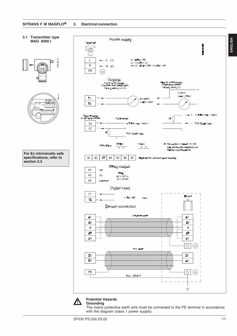
ISH3.1 Transmitter type
MAG 6000 I
3. Electrical connection
Potential HazardsGroundingThe mains protective earth wire must be connected to the PE terminal in accordancewith the diagram (class 1 power supply).
For Ex intrinsically safespecifications, refer tosection 2.5

SITRANS F M MAGFLO®®®®®
12 SFIDK.PS.026.E8.02
EN
GL
ISH
Installation 1) Mains supply 115 to 230 V AC from building installation Class II. A switch or circuit-breaker(max. 15 A) shall be included in the building installation. It must be in close proximity to theequipment and within easy reach of the OPERATOR, and it shall be marked as thedisconnecting device for the equipment.
2) The mains protective earth wire must be connected to the PE terminal, if the earthwire is not connected, personnel can be exposed to 115V/230V.Required cable min. AGW16 or 1.5 Cu wire.
For field wiring installation National Installation Code shall be met of the country, where theflowmeters are installed.Main voltage terminals must be out of reach for OPERATOR to avoid any hazards!
Intrinsically safe terminals!It is an absolute requirement that the wires/terminals of the intrinsically safe circuits cannot getinto contact with the wires of the other cables. The distance between cables/wires therefore mustbe at least 50 mm or otherwise protected.
It is recommended to fasten the cables/wires in a way that they, even in case of an error, cannotget into contact with each other. Make the wire ends as short as possible.
Digital outputIf the internal resistance of the loads exceeds 10KΩ, it is recommended to connect an external1-10 KΩ load resistor in parallel to the load.
3. Electrical connection
When reassembling the unit, make sure that the 2 screws are properly tightened in order to ensurea correct assembly and a proper ground connection.
Cover/insulate the power supply terminals with the plastic cover (to secure sufficient insulation).
TORX 20

SITRANS F M MAGFLO®®®®®
13SFIDK.PS.026.E8.02
EN
GL
ISH
At the MAG 6000 I the current output terminal 31, 32 can be switch between active mode(transmitter powered) to passive mode default (external powered).
3.2 Installation examples
Current output in passivemode
Frequency/pulse output inpassive mode
Active/passive currentoutput
3. Electrical connection
Position A = Active(fatory default MAG 6000 I)
Position B = Passive(fatory default MAG 6000 I) (Ex d)

SITRANS F M MAGFLO®®®®®
14 SFIDK.PS.026.E8.02
EN
GL
ISH 3.2.1 Add-on
communicationmodule
3. Unpack the module and fit into moduleholder.
4. Press the add-on module in the directionshown, until it stops and is firmly seated inposition.
5. Re-insert the complete transmitter modulein reverse order.
1. Open transmitter.
2. Remove electronic insert.
3. Electrical connection
SITRANS F M MAGFLO®®®®®
15SFIDK.PS.026.E8.02
EN
GL
ISH4. Technical data
4.1.1 Dimensions andweight
4.1.1.1 MAG 1100 stan-dard & Ex
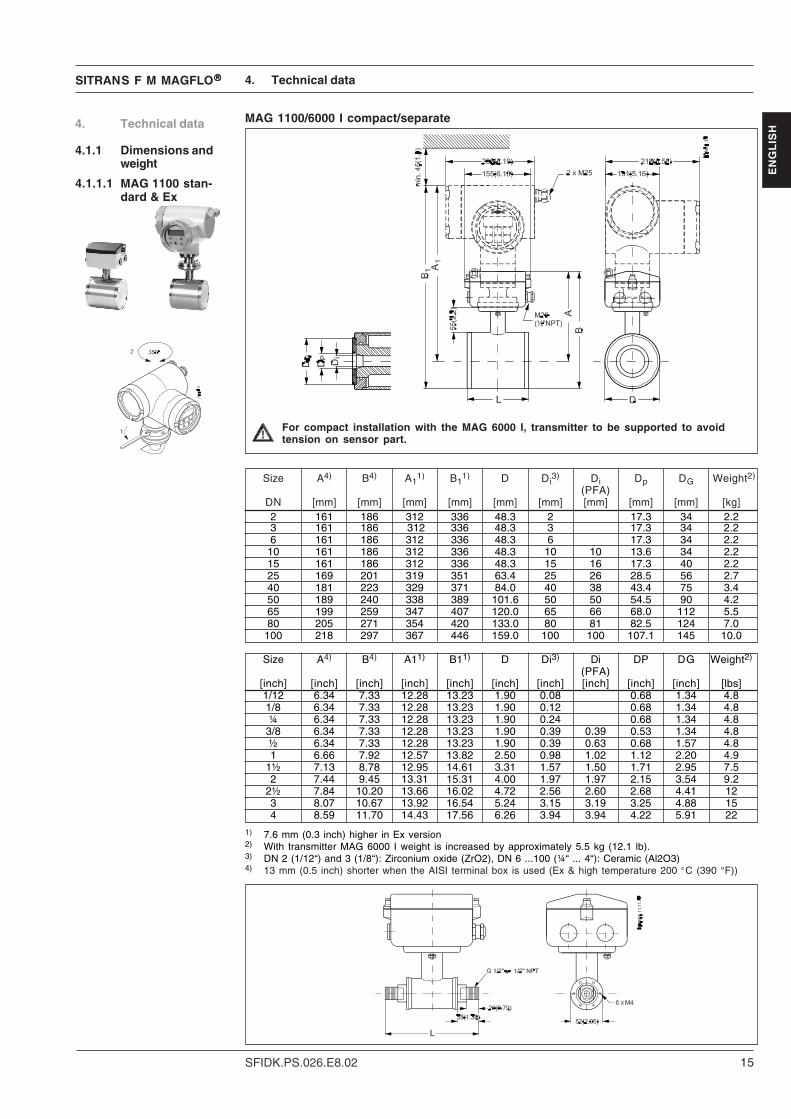
MAG 1100/6000 I compact/separate
4. Technical data
For compact installation with the MAG 6000 I, transmitter to be supported to avoidtension on sensor part.
1) 7.6 mm (0.3 inch) higher in Ex version2) With transmitter MAG 6000 I weight is increased by approximately 5.5 kg (12.1 lb).3) DN 2 (1/12“) and 3 (1/8“): Zirconium oxide (ZrO2), DN 6 ...100 (¼“ ... 4“): Ceramic (Al2O3)4) 13 mm (0.5 inch) shorter when the AISI terminal box is used (Ex & high temperature 200 °C (390 °F))
Size A4) B4) A11) B1
1) D Di3) Di Dp DG Weight2)
(PFA)DN [mm] [mm] [mm] [mm] [mm] [mm] [mm] [mm] [mm] [kg]2 161 186 312 336 48.3 2 17.3 34 2.23 161 186 312 336 48.3 3 17.3 34 2.26 161 186 312 336 48.3 6 17.3 34 2.2
10 161 186 312 336 48.3 10 10 13.6 34 2.215 161 186 312 336 48.3 15 16 17.3 40 2.225 169 201 319 351 63.4 25 26 28.5 56 2.740 181 223 329 371 84.0 40 38 43.4 75 3.450 189 240 338 389 101.6 50 50 54.5 90 4.265 199 259 347 407 120.0 65 66 68.0 112 5.580 205 271 354 420 133.0 80 81 82.5 124 7.0
100 218 297 367 446 159.0 100 100 107.1 145 10.0
Size A4) B4) A11) B11) D Di3) Di DP DG Weight2)
(PFA)[inch] [inch] [inch] [inch] [inch] [inch] [inch] [inch] [inch] [inch] [lbs]1/12 6.34 7.33 12.28 13.23 1.90 0.08 0.68 1.34 4.81/8 6.34 7.33 12.28 13.23 1.90 0.12 0.68 1.34 4.8¼ 6.34 7.33 12.28 13.23 1.90 0.24 0.68 1.34 4.8
3/8 6.34 7.33 12.28 13.23 1.90 0.39 0.39 0.53 1.34 4.8½ 6.34 7.33 12.28 13.23 1.90 0.39 0.63 0.68 1.57 4.81 6.66 7.92 12.57 13.82 2.50 0.98 1.02 1.12 2.20 4.9
1½ 7.13 8.78 12.95 14.61 3.31 1.57 1.50 1.71 2.95 7.52 7.44 9.45 13.31 15.31 4.00 1.97 1.97 2.15 3.54 9.2
2½ 7.84 10.20 13.66 16.02 4.72 2.56 2.60 2.68 4.41 123 8.07 10.67 13.92 16.54 5.24 3.15 3.19 3.25 4.88 154 8.59 11.70 14.43 17.56 6.26 3.94 3.94 4.22 5.91 22

SITRANS F M MAGFLO®®®®®
16 SFIDK.PS.026.E8.02
EN
GL
ISH
4.1.1.2 MAG 1100 FOODstandard & Ex
MAG 1100 FOOD / 6000 I, compact and separate
1) With transmitter type MAG 6000 I installed, weight is increased by approx. 5.5 kg (12.1 lb).2) Ex version 8 mm (0.026 ft) higher
Size L A A12) B B1
2) D Di Di Weight 1)(Al2O3) (PFA)
DN [mm] [mm] [mm] [mm] [mm] [mm] [mm] [mm] [kg]10 64 161 303.7 193.0 335.7 64.0 10 10 2.215 64 161 303.7 193.0 335.7 64.0 15 16 2.225 79 169 312.2 207.8 350.9 77.5 25 26 2.740 94 181 325.9 226.5 371.4 91.0 40 38 3.450 104 189 329.5 248.5 389,0 119.0 50 50 4.265 131 199 342.4 264.0 407.4 130.0 65 66 5.580 156 205 342.9 282.5 420.4 155.0 80 81 7.0
100 186 218 354.9 309.5 446.4 183.0 100 100 10.0
Size L A A12) B B1
2) D Di Di Weight1)(Al2O3) (PFA)
[inch] [inch] [inch] [inch] [inch] [inch] [inch] [inch] [inch] [lb]3/8 2.52 6.34 11.96 7.60 13.22 2.52 0.39 0.39 4.8½ 2.52 6.34 11.96 7.60 13.22 2.52 0.59 0.63 4.81 3.11 6.66 12.29 8.18 13.81 3.05 0.98 1.02 4.9
1½ 3.70 7.13 12.83 8.92 14.62 3.58 1.57 1.50 7.52 4.09 7.44 12.97 9.79 15.31 4.68 1.97 1.97 9.2
2½ 5.16 7.84 13.48 10.40 16.04 5.12 2.56 2.60 12.03 6.14 8.07 13.50 11.13 16.55 6.10 3.15 3.19 15.04 7.32 8.59 13.97 12.19 17.57 7.20 3.94 3.94 22.0
4. Technical data
For compact installation with the MAG 6000 I, transmitter to be supported to avoidtension on sensor part.

SITRANS F M MAGFLO®®®®®
17SFIDK.PS.026.E8.02
EN
GL
ISHMAG 1100 Ex MAG 1100 FOOD Ex
Type Flangeless sensor Hygienic sensor(Sandwich design)
Nominal size mm DN 2, 3, 6, 10, 15, 25, 40, 50, 65, DN 10, 15, 25, 40, 50, 65, 80, 10080, 100
Operating pressure DN 2 - DN 65: 40 bar, DN 80: DN 10-65: 40 bar, DN 80:37.5 bar, DN 100: 30 bar 37.5 bar, DN 100: 30 barVacuum: 1 × 10⁻⁶ bar Vacuum: 1 × 10⁻⁶ bar
Temperature of mediumCeramic −20°C to +120°C −20°C to +120°CTemperature shock (Duration > 1 min.):(Ceramic liner) DN 2, 3: DN 10, 15, 25:
Max. ∆T d ≤ 20°C/min. Max. ∆T d ≤ 15°C/min.DN 6, 10, 15, 25: DN 40, 50, 65:Max. ∆T d ≤ 15°C/min. Max. ∆T d ≤ 10°C/min.DN 40, 50, 65: DN 80, 100:Max. ∆T d ≤ 10°C/min. Max. ∆T d ≤ 5°C/min.DN 80, 100: (Duration d ≤ 1 min., followedMax. ∆T d ≤ 5°C/min. by 10 min. rest):(Duration d ≤ 1 min., followed by10 min. rest): DN 10, 15, 25: Max. ∆T d ≤ 80°CDN 2, 3: Max. ∆T d ≤ 100°C/min. DN 40, 50, 65: Max. ∆T d ≤ 70°CDN 6, 10, 15, 25: Max. ∆T d ≤ 80°C DN 80, 100: Max. ∆T d ≤ 60°CDN 40, 50, 65: Max. ∆T d ≤ 70°CDN 80, 100: Max. ∆T d ≤ 60°C
Ambient temperature Remote transmitter: −40°C to +100°C Remote transmitter: −40°C to +100°CLiner DN 2, 3: Zirkonium oxide (ZrO2 ) Aluminium oxide Al2O3
(ceramics) (ceramics)DN 6 - 100: Aluminium oxide Al2O3
(ceramics)Electrodes DN 2, 3: Platinum sintered
DN 6 - 100: Platinum with gold/ Platinum with gold/titanium brazingtitanium brazing alloy alloy
Enclosure Stainless steel AISI 316 L (1.4404) Stainless steel AISI 316 L (1.4404)Terminal box Stainless steel AISI 316 (1.4436) Stainless steel AISI 316 (1.4436)Fixing studs Stainless steel AISI 304 (1.4301) Stainless steel AISI 304 (1.4301)
Number and size to EN 1092-1:2001Mating flanges/ EN 1092-1:2001, ANSI B16.5 class Hygienic adapters available for:process connections 150 and 300 or equivalent - Direct welding into dairy pipe
- Clamp fitting- Threaded fitting
Gaskets Standard EPDM (max. 150°C, PN 40) Standard EPDM (max. 150°C, PN 40)Option Graphite (max. 200°C, PN 40) Option NBR (max. 100°C, PN 40)Option PTFE (max. 130°C, PN 25)
Cable entries 4 M20 / ½“ NPT 4 M20 / ½“ NPTEnclosure rating Standard IP67 to EN 60529 Standard IP67 to EN 60529
(NEMA 4x) (1 m w.g for 30 min.) (NEMA 4x) (1 m w.g for 30 min.)Option IP68 to EN 60529 (NEMA 6) Option IP68 to EN 60529 (NEMA 6)(10 m w.g. cont.) (10 m w.g. cont.)
Mechanical load 18-1000 Hz random in all directions 18-1000 Hz random in all directions(vibration) to EN 60068-2-36 to EN 60068-2-36
Sensor: 3.17 G/ Sensor: 3.17 G/Compact Ex-d: 1.14 G Compact Ex-d: 1.14 G
Test pressure 80 bar (2 × PN) 80 bar (2 × PN)Approvals See section 2.7 See section 2.7Excitation frequency DN 2 - 65: 6.25 Hz DN 10 - 65: 6.25 Hz
DN 80 - 100: 3.125 Hz DN 80 - 100: 3.125 HzConforms to PED, LVT, EMC PED - 97/23EC, PED, LVT, EMC PED - 97/23EC,
LVD - 73/23 EEC + amendment 93/ LVD - 73/23 EEC + amendment 93/68/EEC, EMC - 89/336 68/EEC, EMC - 89/336
4.1.2 Sensor MAG 1100 Ex& MAG 1100 FOOD Ex
4. Technical data

SITRANS F M MAGFLO®®®®®
18 SFIDK.PS.026.E8.02
EN
GL
ISH
DN A1) A15) B D1 L2) AS TC
3) TE 3)
2129 E, AWWAAS 4087 C-207
PN PN PN PN PN PN Class Class PN Class6, 10 16 25 40 63 100 150 300 16-21- D
35[mm] [mm] [mm] [mm] [mm] [mm] [mm] [mm] [mm] [mm] [mm] [mm] [mm] [mm] [mm] [mm] [mm] [kg]
15 187 338 59 104 200 200 200 200 - - 200 200 200 - - 6 425 187 338 59 104 200 200 200 200 - 260 200 200 200 - 1.2 6 540 197 348 82 124 200 200 200 200 - 280 200 200 200 - 1.2 6 850 205 356 72 139 200 200 200 200 276 300 200 200 200 - 1.2 6 965 212 363 72 154 200 200 200 200 320 350 200 272 200 - 1.2 6 1180 222 373 72 174 200 200 272 272 323 340 272 272 2005) - 1.2 6 12
100 242 393 85 214 250 250 250 250 380 400 250 310 250 - 1.2 6 16125 255 406 85 239 250 250 250 250 420 450 250 335 250 - 1.2 6 19150 276 427 85 282 300 300 300 300 415 450 300 300 300 - 1.2 6 27200 304 455 137 338 350 350 350 350 480 530 350 350 350 - 1.2 8 40250 332 483 137 393 450 450 450 450 550 620 450 450 450 - 1.2 8 60300 357 508 137 444 500 500 500 500 600 680 500 500 500 - 1.6 8 80350 362 513 270 451 550 550 550 550 700 800 550 550 550 - 1.6 8 110400 387 538 270 502 600 600 600 600 750 - 600 600 600 - 1.6 10 125450 418 569 310 563 600 600 600 600 - - 600 640 600 - 1.6 10 175500 443 594 350 614 600 600 625 680 - - 600 730 6006) - 1.6 10 200600 494 645 430 715 600 600 750 750 - - 600 860 6007) - 1.6 10 287700 544 695 500 816 700 700 - - - - - - 700 700 2.0 - 330750 571 722 556 869 - - - - - - - - 750 937 2.0 - 360800 606 757 560 927 800 800 - - - - - - 800 1000 2.0 - 450900 653 804 630 1032 900 900 - - - - - - 900 1125 2.0 - 530
1000 704 906 670 1136 1000 1000 - - - - - - 1000 1250 2.0 - 6601100 755 906 770 1238 - - - - - - - - - - 2.0 - 11401200 810 961 792 1348 1200 1200 - - - - - - 1200 1500 2.0 - 11801400 925 1076 1000 1675 1400 1400 - - - - - - - - 2.0 - 16001500 972 1123 1020 1672 - - - - - - - - - 1875 3.0 - 24601600 1025 1176 1130 1915 1600 1600 - - - - - - - - 3.0 - 21401800 1123 1274 1250 1974 1800 1800 - - - - - - - - 3.0 - 29302000 1223 1374 1375 2174 2000 2000 - - - - - - - - 3.0 - 3665
4.2.1 Dimensions andweight MAG 3100 Ex
MAG 3100 Ex
1) 13 mm shorter with AISI terminal box (Ex and high temperature version)2) When earthing flanges are used, the thickness of the earthing flange must
be added to the build-in length3) TC = Type C grounding ring, TE = Type E grounding ring (Included and
factory mounted on high temperature 180 °C (356 °F) PTFE sensor)4) Weights are approx. (for PN 16) without transmitter
Wei
gh
t 4)EN 1092-1-2001
4. Technical data
ANSI 16.5
5) PN 35 = 272 mm6) PN 35 DN 500 = 625 mm7) PN 35 DN 600 = 750 mm- not available
D = Outside diameter of flange, see flange tables

SITRANS F M MAGFLO®®®®®
19SFIDK.PS.026.E8.02
EN
GL
ISHDN A1) A1
5) B D1 L2) AS TC 3) TE
3)
2129 E, AWWAAS 4087 C-207
PN PN PN PN PN PN Class Class PN Class6, 10 16 25 40 63 100 150 300 16-21- D
35[inch] [inch] [inch] [inch] [inch] [inch] [inch] [inch] [inch] [inch] [inch] [inch] [inch] [inch] [inch] [inch] [inch] [lb]
½ 7.36 13.31 2.32 4.09 7.87 7.87 7.87 7.87 - - 7.87 7.87 - 7.87 - 0.24 111 7.36 13.31 2.32 4.09 7.87 7.87 7.87 7.87 - 10.24 7.87 7.87 - 7.87 0.05 0.24 13
1½ 7.76 13.70 3.23 4.88 7.87 7.87 7.87 7.87 - 11.02 7.87 7.87 - 7.87 0.05 0.24 172 8.07 14.01 2.83 5.47 7.87 7.87 7.87 7.87 10.87 11.81 7.87 7.87 - 7.87 0.05 0.24 28
2½ 8.35 14.29 2.83 6.06 7.87 7.87 7.87 7.87 12.60 13.78 7.87 10.71 - 7.87 0.05 0.24 303 8.74 14.69 2.83 6.85 7.87 7.87 10.71 10.71 12.72 13.39 10.71 10.71 - 7.875) 0.05 0.24 334 9.53 15.47 3.35 8.43 9.84 9.84 9.84 9.84 14.96 15.75 9.84 12.20 - 9.84 0.05 0.24 445 10.04 15.98 3.35 9.41 9.84 9.84 9.84 9.84 16.54 17.72 9.84 13.10 - 9.84 0.05 0.24 556 10.87 16.81 5.39 11.10 11.81 11.81 11.81 11.81 16.34 17.72 11.81 11.81 - 11.81 0.05 0.24 668 11.97 17.91 5.39 13.31 13.78 13.78 13.78 13.78 18.90 20.87 13.78 13.78 - 13.78 0.05 0.31 110
10 13.07 19.02 5.39 15.47 17.72 17.72 17.72 17.72 21.65 24.41 17.72 17.72 - 17.72 0.05 0.31 15512 14.05 20.00 5.39 17.48 19.69 19.69 19.69 19.69 23.62 26.77 19.69 19.69 - 19.69 0.06 0.31 17614 14.25 20.20 10.63 17.76 21.65 21.65 21.65 21.65 27.56 31.50 21.65 21.65 - 21.65 0.06 0.31 24216 15.24 21.18 10.63 19.76 23.62 23.62 23.62 23.62 29.53 - 23.62 23.62 - 23.62 0.06 0.39 27518 16.45 22.40 12.20 22.16 23.62 23.62 23.62 23.62 - - 23.62 25.20 - 23.62 0.06 0.39 38520 17.44 23.39 13.78 24.17 19.69 19.69 24.61 26.77 - - 19.69 28.70 - 24.616) 0.06 0.39 33524 19.45 25.39 16.93 28.15 23.62 23.62 29.53 29.53 - - 23.62 33.80 - 29.537) 0.06 0.39 63028 21.42 27.36 19.69 32.13 27.56 27.56 - - - - - - 34.5 34.45 0.08 - 72530 22.48 28.43 21.89 34.21 - - - - - - - - 29.52 - 0.08 - 83032 23.86 29.80 22.05 36.50 31.50 31.50 - - - - - - 31.50 31.50 0.08 - 99036 25.71 31.65 24.80 40.63 35.43 35.43 - - - - - - 35.43 35.43 0.08 - 116040 27.72 35.67 26.38 44.72 39.37 39.37 - - - - - - 39.37 39.37 0.08 - 145342 27.72 35.67 26.38 44.72 39.37 39.37 - - - - - - 39.37 39.37 0.08 - 145344 29.72 35.67 30.31 48.74 - - - - - - - - - - 0.08 - -48 31.89 37.83 31.18 53.07 47.24 47.24 - - - - - - 47.24 47.24 0.08 - 259254 36.42 42.36 39.37 65.94 55.12 55.12 - - - - - - 55.12 55.12 0.12 - 294060 38.27 44.21 40.15 65.83 - - - - - - - - - - 0.12 - 342266 40.35 46.30 44.49 75.39 63.00 63.00 - - - - - - 63.00 63.00 0.12 - 390472 44.21 50.16 49.21 77.72 70.87 70.87 - - - - - - 70.87 70.87 0.12 - 484678 48.15 54.09 54.13 85.59 78.74 78.74 - - - - - - 78.74 78.74 0.12 - 6806
Wei
gh
t 4)EN 1092-1-2001 ANSI 16.5
1) 0.512 inch shorter with AISI terminal box (Ex and high temperature version)2) When earthing flanges are used, the thickness of the earthing flange must be added to the build-in length3) TC = Type C grounding ring, TE = Type E grounding ring (Included and factory mounted on high temperature 180 °C (356 °F) PTFE sensor)4) Weights are for ANSI 150 without transmitter5) PN 35 = 10.70 inch6) PN 35 DN 500 = 24.61 inch7) PN 35 DN 600 = 29.53 inch- not available
D = Outside diameter of flange, see flange tables
4. Technical data

SITRANS F M MAGFLO®®®®®
20 SFIDK.PS.026.E8.02
EN
GL
ISH Type Sensor with flanges
Nominal size mm DN 15 - DN 2000Temperature of medium1) Temperature classification
Liner: T3 + T4 T5 T6Neoprene (standard) 0 to 70°C 0 to 70°C 0 to 70°CEPDM2) −10 to 95°C −10 to 90°C −10-75°CLinatex® rubber −20 to 70°C −20 to 70°C −20 to 70°CEbonite2) 0 to 95°C 0 to 90°C 0 to 75°CPTFE −20 to 100°C −20 to 90°C −20 to 75°CNovolak −20 to 100°C −20 to 87°C −20 to 72°C
Ambient temperature Remote transmitter: −20°C to 60°COperating pressure3) [[[[[abs.bar]]]]]
Liner:Neoprene 0.01 to 100 bar (0.15 to 1450 psi)EPDM 0.01 to 40 bar (0.15 to 580 psi)Linatex® 0.01 to 40 bar (0.15 to 580 psi)Ebonite 0.01 to 100 bar (0.15 to 1450 psi)PTFE teflon:DN 15 to 600: 0.3 to 50 bar (4 to 725 psi)Novolak 0.01 to 40 bar (0.15 to 580 psi)
Excitation frequency DN 15 - 65: 6.25 HzDN 80/100: 3.125 HzDN 125 - 300: 1.5625 HzDN 350 - 1200: 3.125 Hz
Enclosure rating Standard IP67 to EN 60529 (NEMA 4X) (1 m w.g for 30 min.)Option IP68 to EN 60529 (NEMA 6) (10 m w.g. cont.)
Cable entries 4 Pg 13.5Mechanical load 18-1000 Hz random, 3.17 G rms in all directions to EN 60068-2-36Test pressure 1.5 × PNFlanges Standard DN 15-50: PN 40 (580 psi)
EN 1092-1:20014) DN 65-150: PN 16 (232 psi)Rased face DN 200-1000: PN 10 (145 psi)
DN 1100 -2000: PN 6 (87 psi)Option DN 65-1000: PN 6 (87 psi)
DN 1200-2000: PN 10 (145 psi)DN 200-2000: PN 16 (232 psi)DN 200-600: PN 25 (362 psi)DN 65-600: PN 40 (580 psi)DN 50-400 PN 63 (913 psi)DN 25-350 PN 100 (1450 psi)
ANSI B 16.5 (∼BS 1560) 3/4"-24": Class 150 (20 bar) (290 psi)3/4"-24": Class 300 (50 bar) (725 psi)
AS 2129 3/4"-48": Table D/EAS 4087 PN 16 (DN 50 - 1200, 14 bar) (203 psi)
PN 21 (DN 50 - 600, 21 bar) (304 psi)PN 35 (DN 50 - 600, 35 bar) (507 psi)
AWWA C-207 28"-78": Class D (10 bar) (145 psi)Electrodes Standard AISI 316 Ti (1.4571)
Option Hastelloy C-276, Platinum / Iridium, Titanium, AISI 316 Ti CeramicCoated, Tantalum
PE - electrodes Standard As measuring electrodes (except PTFE)Measuring pipe Standard AISI 304 (1.4301)
Option AISI 316 L (1.4404)Flange and Standard Carbon steelhousing material Corrosion-resistant two-component coating (min. 150 µm)
Option AISI 304 (1.4301) flanges and carbon steel housing.Coating as above
Option AISI 316 L (1.4404) flanges and housingEx-approval See section 2.7; Is interface data see section 2.5Conforms to PED, LVD, EMC PED - 97/23EC, LVD - 73/23 EEC +
amendment 93/68/EEC, EMC - 89/336 EEX
1) The maximum fluid temperature may be further limited by the approval temperature ratings, see section 2.72) With WRC (Water Research Council, UK) approval3) Maximum operating pressure decreases with increasing operating temperature and with stainless steel flanges4) EN 1092-1, DIN 2501 & BS 4504 have the same mating dimensions
4.2.2 Sensor MAG 3100 Ex
4. Technical data

SITRANS F M MAGFLO®®®®®
21SFIDK.PS.026.E8.02
EN
GL
ISH
MAG 5100 W, compact/separate4.2.3 Dimensions andweight MAG 5100 W
mm inch mm inch mm inch mm inch mm inch mm inch mm inch mm inch25 1" 187 7.4 340 13.4 N/A N/A N/A N/A 200 7.9 200 7.9 N/A N/A40 1½” 197 7.8 350 13.8 N/A N/A N/A N/A 200 7.9 200 7.9 N/A N/A50 2" 188 7.4 341 13.4 N/A N/A 200 7.9 N/A N/A 200 7.9 N/A N/A65 2½” 194 7.6 347 13.7 N/A N/A 200 7.9 N/A N/A 200 7.9 N/A N/A80 3" 200 7.9 353 13.9 N/A N/A 200 7.9 N/A N/A 200 7.9 N/A N/A100 4" 207 8.1 360 14.2 N/A N/A 250 9.8 N/A N/A 250 9.8 N/A N/A125 5" 217 8.5 370 14.6 N/A N/A 250 9.8 N/A N/A 250 9.8 N/A N/A150 6" 232 9.1 385 15.2 N/A N/A 300 11.8 N/A N/A 300 11.8 N/A N/A200 8" 257 10.1 410 16.1 350 13.8 350 13.8 N/A N/A 350 13.8 N/A N/A250 10" 284 11.2 437 17.2 450 17.7 450 17.7 N/A N/A 450 17.7 N/A N/A300 12" 310 12.2 463 18.2 500 19.7 500 19.7 N/A N/A 500 19.7 N/A N/A350 14" 382 15.0 535 21.1 550 21.7 550 21.7 N/A N/A 550 21.7 N/A N/A400 16" 407 16.0 560 22.1 600 23.6 600 23.6 N/A N/A 600 23.6 N/A N/A450 18" 438 17.2 591 23.3 600 23.6 600 23.6 N/A N/A 600 23.6 N/A N/A500 20" 463 18.2 616 24.3 600 23.6 600 23.6 N/A N/A 600 23.6 N/A N/A600 24" 514 20.2 667 26.3 600 23.6 600 23.6 N/A N/A 600 23.6 N/A N/A700 28" 564 22.2 717 28.2 700 27.6 700 27.6 N/A N/A N/A N/A 700 27.6750 30" 591 23.3 744 29.3 N/A N/A N/A N/A N/A N/A N/A N/A 750 29.5800 32" 616 24.3 779 30.7 800 31.5 800 31.5 N/A N/A N/A N/A 800 31.5900 36" 663 26.1 826 32.5 900 35.4 900 35.4 N/A N/A N/A N/A 900 35.41000 40" 714 28.1 877 34.5 1000 39.4 1000 39.4 N/A N/A N/A N/A 1000 39.4 42" 714 28.1 877 34.5 N/A N/A N/A N/A N/A N/A N/A N/A 1000 39.41100 44" 765 30.1 928 36.5 N/A N/A N/A N/A N/A N/A N/A N/A 1100 43.31200 48" 820 32.3 983 38.7 1200 47.2 1200 47.2 N/A N/A N/A N/A 1200 47.2
AWWANominal
sizeA L
PN 16 PN 40 Class 150
4. Technical data
A1
350 14" 362 14.3 515 20.3 550 21.7 550 21.7 N/A N/A 550 21.7 N/A N/A400 16" 387 15.2 540 21.3 600 23.6 600 23.6 N/A N/A 600 23.6 N/A N/A450 18" 418 16.5 571 22.5 600 23.6 600 23.6 N/A N/A 600 23.6 N/A N/A500 20" 443 17.4 596 23.5 625 24.6 625 24.6 N/A N/A 680 26.8 N/A N/A600 24" 494 19.4 647 25.5 750 29.5 750 29.5 N/A N/A 820 32.3 N/A N/A700 28" 544 21.4 697 27.4 875 34.4 875 34.4 N/A N/A N/A N/A 875 34.4750 30" 571 22.5 724 28.5 N/A N/A N/A N/A N/A N/A N/A N/A 937 36.9800 32" 606 23.9 759 29.9 1000 39.4 1000 39.4 N/A N/A N/A N/A 1000 39.4900 36" 653 25.7 806 31.7 1125 44.3 1125 44.3 N/A N/A N/A N/A 1125 44.31000 40" 704 27.7 857 33.7 1250 49.2 1250 49.2 N/A N/A N/A N/A 1250 49.2 42" 704 27.7 857 33.7 N/A N/A N/A N/A N/A N/A N/A N/A 1250 49.21100 44" 755 29.7 908 35.7 N/A N/A N/A N/A N/A N/A N/A N/A 1375 54.11200 48" 810 31.9 963 37.9 1500 59.1 1500 59.1 N/A N/A N/A N/A 1500 59.1
New dimension fromDN 350 to DN 1200
Sensor with old build-indimensions arediscontinued
PN 10

SITRANS F M MAGFLO®®®®®
22 SFIDK.PS.026.E8.02
EN
GL
ISH
4. Technical data
Weight Nominal size PN 10 PN 16 PN 40 Class 150/ ASAWWA
[mm] [inch] [kg] [lbs] [kg] [lbs] [kg] [lbs] [kg] [lbs] [kg] [lbs]25 1 - - - - 4 9 4 9 4 940 1½ - - - - 7 15 6 13 7 1550 2 - - 9 20 - - 8 20 9 2065 2½ - - 10.7 24 - - 11 24 10.7 2480 3 - - 11.6 26 - - 13 28 11.6 26100 4 - - 15.2 33 - - 19 41 15.2 33125 5 - - 20.4 45 - - 24 52 20.4 45150 6 - - 26 57 - - 29 64 26 57200 8 48 106 48 106 - - 56 124 48 106250 10 64 141 69 152 - - 79 174 69 152300 12 76 167 86 189 - - 110 243 86 189350 14 104 229 125 274 - - 139 307 115 254400 16 119 263 143 314 - - 159 351 125 277450 18 136 299 173 381 - - 182 400 141 311500 20 163 359 223 491 - - 225 495 189 418600 24 236 519 338 744 - - 320 704 301 664700 28 270 595 314 692 - - 273 602 320 704750 30 - - - - - - 329 725 - -800 32 346 763 396 873 - - 365 804 428 944900 36 432 951 474 1043 - - 495 1089 619 13621000 40 513 1130 600 1321 - - 583 1282 636 1399
42 - - - - - - 687 1512 - -44 - - - - - - 763 1680 - -
1200 48 643 1415 885 1948 - - 861 1896 813 1789
- not available
With transmitter MAG 5000 and MAG 6000 compact, weight is increased by approximately 0.8 kg (1.8 lbs),with MAG 6000 I, weight is increased by 5.5 kg (12.1 lb).

SITRANS F M MAGFLO®®®®®
23SFIDK.PS.026.E8.02
EN
GL
ISH
4.2.4 Sensor MAG 5100 W
1) EPDM liner approvals only.2) For sizes greater than 600 mm PED conformity is available as a cost added option, the basic unit will only carry the LVD (Low Voltage Directive)
and EMC approval.3) NSF and Belgaque liner approval still pending.
4. Technical data
Type Sensor with flangesDesign Full bore sensor Coned bore sensor Full bore sensorNominal size mm 25-40 50-300 350-1200Liner NBR Hard Rubber NBR Hard Rubber NBR Hard Rubber
or EPDM or EPDM or EPDMLiner approvals1) WRAS (WRc) - (UK), NSF3) - (US), ACS - (FR), Belgaque3) - (B),
KTW - (D), DVGW-W270 - (D)Medium temperature −10 to 70°C (14 to 160°F)Ambient temperatureRemote transmitter −40 to 90°C
Compact transmitter −20 to 50°COperating pressure 0.01 to 40 bar 0.03 to 20 bar 0.01 to 16 barExcitation frequency 12.5 Hz 50-65 mm: 12.5 Hz DN 350-DN 450: 3.125 Hz
80-150 mm: 6.25 Hz DN 500-DN 1200: 1.5625 Hz200-300 mm: 3.125 Hz
Enclosure rating Standard IP 67 to EN 60529 1 m w.g. for 30 minutesOption IP 68 to EN 60529 10 m w.g. continuously
Cable entries 4 M20 / ½"NPTMechanical load 18-1000 Hz random, 3.17 G rms in all directions to EN 60068-2-36Test pressure 1.5 × nominal pressureFlanges
EN 1092-1 Standard PN 40 50-150 mm: PN 16 PN 10200-300 mm: PN 10
Option 200-300 mm: PN 16 PN 16ANSI B16.5 Standard Class 150 lb Class 150 lb 14"-24": Class 150 lbAWWA C-207 Standard 28"-48": Class DAS 4087 Standard PN 16 (DN 50 - 1200, 14 bar)
Pressure drop at 3 m/sec. As straight pipe Max. 25 mbar As straight pipeElectrodes Hastelloy C276PE/grounding electrodes
Standard Hastelloy C276Measuring pipe/meter body AISI 304 (1.4301) AISI 304 (1.4301) AISI 304 (1.4301)Flanges Carbon steelHousing Carbon steelSurface finish Two component epoxy Polyester powder coat Two component epoxy
min. 150 microns min. 100 microns min. 150 micronsColour Siemens light basic 700Approvals Conforms to PED - 97/23EC, LVD - 73/23 EEC + amendment 93/68/EEC, EMC - 89/336 EEC2)

SITRANS F M MAGFLO®®®®®
24 SFIDK.PS.026.E8.02
EN
GL
ISH
4. Technical data
Current output Current 0-20 mA, 4-20 mA or 4-20 mA + alarm(Active or Load < 560 ohmpassive) Time constant 0.1-30 s adjustable
Ex-version Passive default / Non Ex-version Active defaultDigital output Frequency 0-10 kHz, 50% duty cycle
Time constant 0.1-30 s adjustablePassive 3-30 V DC, 1 KΩ ≤ Rload ≤ 10 KΩ
Ex output characteristics Refer to section 2.5(Terminals: 56-57)
Relay Time constant Changeover relay, time constant same as current time constantLoad 42 V AC/2 A, 24 V DC/1A
Ex output characteristics Refer to section 2.5(Terminals: 31-32)
Digital input 11-30 V DC, Ri = 4.4 KΩActivation time 50 ms
Current I11 V DC = 2.5 mA, I30 V DC = 7 mAFunctions Flow rate, 2 totalizers, low flow cut-off, empty pipe cut-off, flow
direction, error system, operating time, uni/bidirectional flow, limitswitches, pulse output
Galvanic isolation All inputs and outputs are galvanically isolatedCut-off Low flow 0-9.9% of maximum flow
Empty pipe Detection of empty pipe1)Totalizer Two eight-digit counters for forward, net or reverse flowDisplay Background illumination with alphanumerical text, 3 × 20 characters
to indicate flow rate, totalized values, settings and faultsReverse flow indicated by negative sign
Time constant Time constant as current output time constantZero point adjustment AutomaticElectrode input impedance > 1 x 10¹⁴ ΩExcitation frequency Sensor size depending pulsating DC currentAmbient temperature Display version during operation: −20 to +60°C
During storage: −40 to +70°C (RH max. 95%)Communication Standard Prepared for customer mounted add-on modules
Optional HART, Profibus PA on Ex versionCompact Enclosure material Die cast Aluminium, painted
Enclosure rating IP67/NEMA 4X to EN 60529 and DIN 40050 (1 m w.g. for 30 minutes)Mechanical load 18-1000 Hz random, 3.17 G rms in all directions to EN 60068-2-36
EMC performance EN 61326Supply voltage MAG 6000 I: 18-90 V DC / 115-230 V AC
MAG 6000 I (Ex d): 115-230 V AC or 18-30 V DCPower consumption 230 V AC: 21,5 VA
24 V DC: 12 W, IN = 380 mA, IST = 1A (3 ms)Profibus PA Refer to section 2.5
(Terminals: 95-96)
4.3 Transmitter typeMAG 6000 IAccuracy 0.25%
1) Special cable required in separate mounted installation

SITRANS F M MAGFLO®®®®®
25SFIDK.PS.026.E8.02
EN
GL
ISH
4. Technical data
4.4 Output characteris-tics MAG 6000 I
Output characteristics Bidirectional mode Unidirectional mode0-20 mA
4-20 mA
Frequency
Pulse output
RelayPower down Active
Error relay No error Error
Limit switch or 1 set point 2 set pointsdirection switch
Low flow Intermediate flow(Reverse flow)High flow High flow/(Forward flow) Low flow
Batch on digitaloutput
Batch on relay Hold Batch

SITRANS F M MAGFLO®®®®®
26 SFIDK.PS.026.E8.02
EN
GL
ISH
Communication mode Basic settings Operator active
Service mode Output Operator inactive
Operator menu External input
Product identity Sensor characteristics
Language mode Reset mode
5. Commissioning
5.1 Keypad and displaylayout
Keypad The keypad is used to set the flowmeter. The function of the keys is as follows:
TOP UP KEY This key (hold 2 sec.) is used to switch between operator menuand setup menu. In the transmitter setup menu, a short press willcause a return to the previous menu.
FORWARD KEY This key is used to step forward through the menus. It is the onlykey normally used by the operator.
BACKWARD KEY This key is used to step backward through the menus.
CHANGE KEY This key changes the settings or numerical values.
SELECT KEY This key selects the figures to be changed.
LOCK/UNLOCK KEY This key allows the operator to change settings and givesaccess to submenus.
Display The display is alphanumerical and indicates flow values, flowmeter settings and error messages.
The upper line is for primary flow readings and will always show either flow rate, totalizer 1 or totalizer2. The line is divided into 3 fields.
S: Sign fieldP: Primary field for numerical valueU: Unit field
The centre line is the title line (T) with individual information according to the selected operatoror setup menu.
The lowest line is the subtitle line (ST) which either will add information to the title line or keepindividual information independent of the title line.
F: The alarm field. Two flashing triangles will appear by a fault condition.
M: The mode field. The symbols indicate the following.
Ready for change Access to submenu
Value locked RESET MODE: Zero setting oftotalizers and initialization of setting
L: The lock field. Indicates the function of the lock key.
5. Commissioning
With the capacitive touch keypad operation is achived without any open lids. An LED light givesa feedback.

SITRANS F M MAGFLO®®®®®
27SFIDK.PS.026.E8.02
EN
GL
ISH5.2
Menu build-upThe menu structure of a specific transmitter type is shown in a menu overview map.Details of how a specific parameter is set is shown in a menu detail map for the specific parameter.A detail map is valid for each type of transmitter if not indicated otherwise. The menu structure isvalid for the title and subtitle line only. The upper line is for primary readings only and will alwaysbe active with either flowrate, totalizer 1 or totalizer 2.
The menu is built up in two parts. An operator menu and a setup menu.
Operator menuThe operator menu is for daily operation. The operator menu is customised in the operator menusetup. The transmitter always starts in operator menu No. 1. The page forward and page backwardkeys are used to step through the operator menus.
Setup menuThe setup menu is for commissioning and service only.
Access to the setup menu is gained by pressing the top up key for 2 seconds. The setup menuoperates in two modes:
• View mode
• Setup mode
View mode is a read only mode. The pre-selected settings can only be scanned.
Setup mode is a read and write mode. The pre-selected settings can be scanned and changed.Access to the setup mode is password protected. The factory set password is 1000.
Access to a submenu in the set up menu is gained by the lock key. A short press on a top up keywill bring you back to the previous menu. A long press (2 sec.) on the top up key will exit the setupmenu and bring you back to operator menu No. 1.
5.2.1Password
The SETUP MENU can be operated in two different modes:
VIEW MODE (Read only)CHANGE MODE (Read and write mode)
Access to view mode is always gained by pressing the forward key when in the password menu.
Access to change mode is password protected. The password is factory set to 1000, but can bechanged to any value between 1 and 9999 in the change password menu.
The factory setting of 1000 can be re-established as follows:
• Switch off power suppply
• Press the TOP UP key and switch on the power supply
• Release the key after ROM and RAM tests are completed
The user code is now reset to 1000.
5. Commissioning

SITRANS F M MAGFLO®®®®®
28 SFIDK.PS.026.E8.02
EN
GL
ISH 5.3 MAG 6000 I
5. Commissioning

SITRANS F M MAGFLO®®®®®
29SFIDK.PS.026.E8.02
EN
GL
ISH5.4
Basic settings
Comma for flow rate, totalizer 1 and totalizer 2 can be individually positioned.• open the respective window.• ensure that the cursor is positioned below the comma. Use the SELECT KEY .• move the comma to the requested position. Use the CHANGE KEY .
Units are changed by means of the CHANGE KEY with the cursor placed below the unitselected. Select units (cursor moved) by means of the SELECT KEY .
Totalizer 2 is not visible when batch is selected as digital output.
Qmax. 2 - is only visible when it has been choosen as external input.
Main frequencyTo select the main power supply frequency correspondingto the country in which the flowmeter is installed.(US = 60 Hz)
Flow directionSelect the correct flow direction in the pipe
Qmax.Sets the measuring range, the analog outputs and thefrequency output. Value, decimal point, unit and time canbe set individually (setting is dimension dependent).
Qmax.2Sets the measuring range, the analog outputs and thefrequency output. Value, decimal point, unit and time canbe set individually (setting is dimension dependent).Only visible when it has been choosen as external digitalinput.
TotalizersTo set unit and decimal point.
Low flow cutt offTo set a % of selected Qmax.. To filter noise in theinstallation. Influences display and all outputs.
Error levelTo select which error level, the flowmeter will detects anerror.
Empty pipe cut offSet on - the alarm will indicate when sensor isrunning empty. All readings, display and outputs willindicate zero.
5. Commissioning

SITRANS F M MAGFLO®®®®®
30 SFIDK.PS.026.E8.02
EN
GL
ISH 5.4.1
Outputs
Current outputProportional to flowrate(Terminal 31 and 32)
The current output must be set off when not used.
4 - 20 mA + alarm: Alarm mode = 3.6 mA* Not for MAG 6000 I
5.4.2Digital and relay outputs
Error level
Digital outputPulse/volume(Terminal 56, 57)
Digital outputFrequencyProportional to flowrate(Terminal 56, 57)
Error number
*
5. Commissioning

SITRANS F M MAGFLO®®®®®
31SFIDK.PS.026.E8.02
EN
GL
ISHLimit/direction
Limit switches are available for both digital as well as relay output.
Direction mode: 1 set point at 0% flow; hysteresis 5%.If 2 set points must activate 2 separate outputs, a single set point has to be selected individuallyfor digital as well as relay outputs.
Batch
5.4.3Relay outputs
Cleaning
! Cleaning not possiblewith MAG 6000 I.
5.4.4External input
The relay output must always be used to operate the cleaning unit when a cleaning unit has beeninstalled together with the transmitter. The relay output cannot be used for other purposes.
NoteWhen batch function is on relay - the pulse/frequency output is not possible.
5. Commissioning

SITRANS F M MAGFLO®®®®®
32 SFIDK.PS.026.E8.02
EN
GL
ISH 5.4.5
Sensor characteristics
5.4.6Reset mode
If “SENSORPROM notinstalled” is shown, refer tochapter 6 (depending ontype of mounting configura-tion).
5. Commissioning
SITRANS F M MAGFLO®®®®®
33SFIDK.PS.026.E8.02
EN
GL
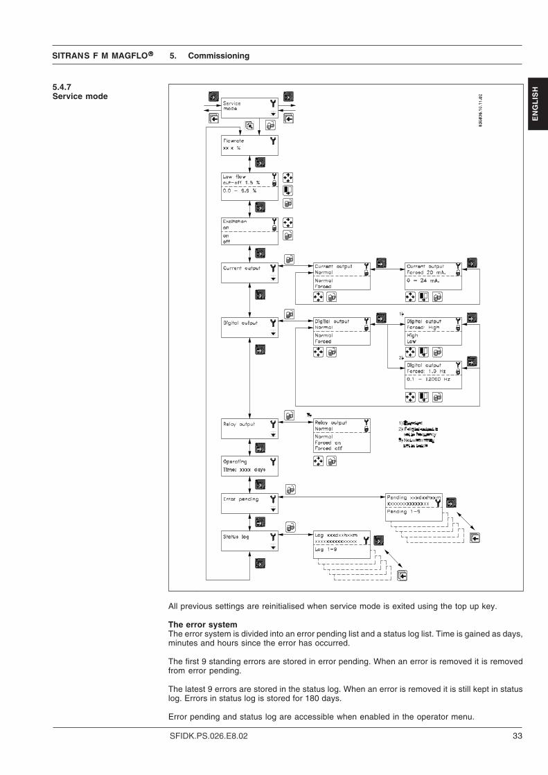
ISH5.4.7
Service mode
All previous settings are reinitialised when service mode is exited using the top up key.
The error systemThe error system is divided into an error pending list and a status log list. Time is gained as days,minutes and hours since the error has occurred.
The first 9 standing errors are stored in error pending. When an error is removed it is removedfrom error pending.
The latest 9 errors are stored in the status log. When an error is removed it is still kept in statuslog. Errors in status log is stored for 180 days.
Error pending and status log are accessible when enabled in the operator menu.
5. Commissioning

SITRANS F M MAGFLO®®®®®
34 SFIDK.PS.026.E8.02
EN
GL
ISH 5.4.8
Operator menu setup
The upper line is always active and can never be deselected.
The two lower lines are for individual operator information. Information which the operator canscroll through with the forward key.
• A closed lock key in the operator menu setup, means that the menu is enabled when viewingthe operator menu.
• An open lock key symbol, means that the menu is not available in the operator menu.
The middle line can either be used as a heading “Text line” for the lower line, or as a flow reading.A flow reading can be individually selected for each menu.
The lower line may be used for an additional flow reading to the reading already available in theupper line.
Text means that the text for the chosen measured value isshown.For example if text is chosen in line 2 and flow rate ischosen in line 3, the text “flow rate” is shown in line 2 andthe measured flow rate value is show in line 3.
5. Commissioning

SITRANS F M MAGFLO®®®®®
35SFIDK.PS.026.E8.02
EN
GL
ISH5.4.9
Product identity
Software version of add-on module is only available if the add-on module has been installed.
5.4.10Change password
5. Commissioning

SITRANS F M MAGFLO®®®®®
36 SFIDK.PS.026.E8.02
EN
GL
ISH 5.4.11
Language mode
5.4.12HART®®®®® communication
5. Commissioning

SITRANS F M MAGFLO®®®®®
37SFIDK.PS.026.E8.02
EN
GL
ISH5.5
Settings availableParameter Factory settings Settings availablePasswordDefault value 1000Password 1000 1000 - 9999Basic settingsFlow direction Positive Positive, negativeQmax. Dim. dependent Dim. dependent - Volume units Dim. dependent m3, ml, l, kl, hl, Ml, ft3, in3, USG, USkG, USMG, UKG,
UKMG, USBBL- Time units Dim. dependent Sec., min., hour, dayTotalizer 1 Forward Forward, reverse, net - Totalizer 1 units Dim. dependent m3, ml, l, kl, hl, Ml, ft3, in3, USG, USkG, USMG, UKG,
UKMG, USBBLTotalizer 2 Reverse Forward, reverse, net - Totalizer 2 units Dim. dependent m3, ml, l, kl, hl, Ml, ft3, in3, USG, USkG, USMG, UKG,
UKMG, USBBLLow flow cut-off 1.5 % 0 - 9.9 %Empty pipe Off Off, onError level Warning Fatal, permanent, warningOutputCurrent output Off On/off, uni-/bidirectional, 0/4 - 20 mA - Time constant 5 s 0.1 - 30 sDigital output Pulse Error, direction/limit, batch, frequency, pulse, error
no., offRelay output Error Error, direction/limit, cleaning, error No., offDirection/limit switch Off 1 set point/2 set points, −100 - 100% - Hysteresis 5% 0.0 - 100%Batch Off - Batch quantity 0 Dim. dependent - Batch compensation 0 −100 - 100 m3
- Batch counter Down Up/down - Time constant 0.1 s 0.1 - 30 sFrequency Off 500 Hz, 1 kHz, 5 kHz, 10 kHz - Time constant 5 s 0.1 - 30 sPulse On - Pulse polarity Positive Positive/negative - Pulse width 66 ms 64 µs, 130 µs, 260 µs, 510 µs, 1.0 ms, 2.0 ms,
4.1 ms, 8.2 ms, 16 ms, 33 ms, 66 ms, 130 ms,260 ms, 520 ms, 1.0 s, 2.1 s, 4.2 s.
- Volume/pulse Dim. dependent Dim. dependent - Time constant 0.1 s 0.1 - 30 sElectrode cleaning Off Off/cleaning - Cleaning cycle time 24 h 1 - 240 hExternal inputExternal input Off Batch, reset totalizer, freeze output, forced output, off - Batch Start, hold/continue, stop, Qmax. 2Sensor characteristicsCorrection factor 1 0.85 - 2.00Language English English, German, French, Danish, Swedish, Finnish,
Spanish, Russian, Italian, Portuguese and PolishOperator menuPrimary field Flow rate Flow rate, Totalizer 1, Totalizer 2Title/subtitle line Flow rate Flow rate, Flow rate %, Qmax., Totalizer 1, Totalizer 2,
Totalizer 1 reset, Totalizer 2 reset, Batch start/paused/stop, Batch cycle counter, Batch cyclecounter reset, Sensor size, Sensor type, Errorpending, Status log, Tag No.
The transmitter is delivered with factory settings ready to measure the actual flow.
5. Commissioning

SITRANS F M MAGFLO®®®®®
38 SFIDK.PS.026.E8.02
EN
GL
ISH DN Qmax.
MAG 5100 W MAG 1100,
3100, 3100 W Volume/ Pulse Totalizer
mm [inches] fac.set. min. max. min. max. unit pulse unit unit2 1/12 30 - - 3.9 156.7 l/h 1 l l3 1/8 70 - - 6.4 254.5 l/h 1 l l6 1/4 300 - - 25.5 1017 l/h 1 l l10 3/8 900 - - 70.7 2827 l/h 1 l l15 1/2 2000 - - 159.1 6361 l/h 1 l l25 1 5000 442.0 17671 442.0 17671 l/h 10 l l40 11/2 12 1.2 45 1.2 45 m3/h 10 l l50 2 20 1.6 63 1.8 70 m3/h 10 l l65 21/2 30 2.5 100 3.0 119 m3/h 100 l l80 3 50 4.0 160 4.6 180 m3/h 100 l l
100 4 120 6.3 250 7.1 282 m3/h 100 l l125 5 180 10.0 400 11.1 441 m3/h 100 l m3
150 6 250 15.7 629 16.0 636 m3/h 100 l m3
200 8 400 24.9 997 28.3 1130 m3/h 1 m3 m3
250 10 700 40.0 1600 44.2 1767 m3/h 1 m3 m3
300 12 1000 62.5 2500 63.7 2544 m3/h 1 m3 m3
350 14 1200 86.6 3463 86.6 3463 m3/h 1 m3 m3
400 16 1800 113.1 4523 113.1 4523 m3/h 1 m3 m3
450 18 2000 143.2 5725 143.2 5725 m3/h 1 m3 m3
500 20 3000 176.8 7068 176.8 7068 m3/h 1 m3 m3
600 24 4000 254.5 10178 254.5 10178 m3/h 10 m3 m3
700 28 5000 346.4 13854 346.4 13854 m3/h 10 m3 m3
750 30 6000 397.7 15904 397.7 15904 m3/h 10 m3 m3
800 32 7000 452.4 18095 452.4 18095 m3/h 10 m3 m3
900 36 9000 573.0 22902 573.0 22902 m3/h 10 m3 m3
1000 40 12000 707.0 28274 707.0 28274 m3/h 10 m3 m3
1100 44 14000 855.3 34211 855.3 34211 m3/h 10 m3 m3
1200 48 15000 1018.0 40715 1018.0 40715 m3/h 10 m3 m3
1400 54 25000 - - 1385.5 55417 m3/h 10 m3 m3
1500 60 30000 - - 1590.5 63617 m3/h 10 m3 m3
1600 66 35000 - - 1809.6 72382 m3/h 10 m3 m3
1800 72 40000 - - 2290.3 91608 m3/h 10 m3 m3
2000 78 45000 - - 2827.5 113097 m3/h 10 m3 m3
5.5.1Dimension dependentfactory settings
Volume/pulse or batch quantity
min. max.DN 2 3.6 µl 0.09 m3
DN 3 5.9 µl 0.15 m3
DN 6 24 µl 0.62 m3
DN 10 65 µl 1.72 m3
DN 15 147 µl 3.86 m3
DN 25 409 µl 10.7 m3
DN 40 1.05 ml 27.5 m3
DN 50 1.64 ml 42.9 m3
DN 65 2.77 ml 72.5 m3
DN 80 4.19 ml 110 m3
DN 100 6.54 ml 172 m3
DN 125 10.2 ml 268 m3
DN 150 14.7 ml 386 m3
DN 200 26.2 ml 686 m3
DN 250 40.9 ml 1072 m3
DN 300 58.9 ml 1544 m3
DN 350 80.2 ml 2102 m3
DN 400 105 ml 2745 m3
DN 450 133 ml 3474 m3
DN 500 164 ml 4289 m3
DN 600 236 ml 6177 m3
DN 700 321 ml 8407 m3
DN 800 419 ml 10981 m3
DN 900 530 ml 13897 m3
DN 1000 654 ml 17157 m3
DN 1200 942 ml 24706 m3
DN 2000 2.62 l 68629 m3
5.5.2Dimension dependentbatch and pulse outputsettings
5. Commissioning

SITRANS F M MAGFLO®®®®®
39SFIDK.PS.026.E8.02
EN
GL
ISH
5.6.2Batch
A batch can be started, paused or stopped from the operator menu, in addition to the externallyoperated batch control. The batch is controlled using the lock and the top up keys.
The lock key:• Starts the batch• Holds the batch (pause) when pressed during batching• Restarts the batch to continue when pressed during a pause.
The top up key resets a batch completely during a pause.
The accumulated number of performed batches can be viewed when enabled in the operatormenu setup.
The batch cycle counter is reset by pressing the lock key in the “batch cycle cnt reset” menu.
Batch cycle counter
Batch cycle counter reset
5.6Flow rate
The 1st display line is always active and shows the value enabled in the operator menu setup.• Flow rate• Totalizer 1• Totalizer 2
The 2nd and 3rd display lines are individually set in the operator menu. The page forward key stepsthrough the enabled settings.• Flow rate• Totalizer• Totalizer reset• Batch control• Batch cycle counter• Batch cycle counter reset• Pipe size• Sensor type• Pending errors• Status log• Tag No.
5.6.1Totalizer
A totalizer is reset by pressing the lock key when the corresponding totalizer reset window is open.
5. Commissioning

SITRANS F M MAGFLO®®®®®
40 SFIDK.PS.026.E8.02
EN
GL
ISH Error Error text #Comment Outputs Input
No. Remedy text status status1 I1 - Power on
OK Power on has happened Active Active2 I2 - Add-on module
Applied A new module has been applied to the system Active Active3 I3 - Add-on module
Install An add-on module is defect or has been removed.This can be an internal add-on module Active Active
4 I4 - Param. correctedOK A less vital parameter in the transmitter has been re-
placed by its default value Active Active20 W20 - Totalizer 1
Reset manually During initialisation the check of the saved totalizervalue has failed. It is not possible to rely on thesaved totalizer value anymore. The totalizer valuemust be reset manually in order to rely on futurereadings Active Active
20 W20 - Totalizer 2Reset manually During initialisation the check of the saved totalizer
value has failed. It is not possible to rely on thesaved totalizer value anymore. The totalizer valuemust be reset manually in order to rely on futurereadings Active Active
21 W21 - Pulse overflowAdj. pulse settings Actual flow is too big compared with pulse width and Reduced
volume/pulse pulse width Active22 W22 - Batch timeout
Check installation Duration of batching has exceeded a predefined Batch out-max. time put on zero Active
23 W23 - Batch overrunCheck installation Batch volume has exceeded a predefined maximum Batch out-
overrun volume put on zero Active24 W24 - Batch neg. flow
Check flow direction Negative flow direction during batch Active Active30 W30 - Overflow
Adj. Qmax. Flow is above Qmax. settings Max. 120 % Active31 W31 - Empty pipe
Pipe is empty Zero Active40 P40 - SENSORPROM®
Insert/change SENSORPROM® unit not installed Active Active41 P41 - Parameter range
Switch off and on A parameter is out of range. The parameter could notbe replaced by its default value. The error will dis-appear at the next power-on Active Active
42 P42 - Current outputCheck cables Current loop is disconnected or the loop resistance
is too big Active Active43 P43 - Internal error
Switch off and on Too many errors occured at the same timeSome errors are not detected correctly Active Active
44 P44 - CT SENSORPROM®
SENSORPROM® unit has been used as CT version Active Active60 F60 - CAN comm. error
Transmitter/AOM CAN bus communication error. An add-on module, thedisplay module or the transmitter is defect Zero Inactive
61 F61 - SENSORPROM® errorReplace It is not possible to rely on the data in SENSOR-
PROM® unit anymore Active Active62 F62 - SENSORPROM® ID
Replace The SENSORPROM® unit ID does not comply with theproduct ID.The SENSORPROM® unit is from another type ofproduct MASSFLO®, SONOFLO® etc. Zero Inactive
63 F63 - SENSORPROM®
Replace It is not possible to read from the SENSORPROM®
unit anymore. Active Active70 F70 - Coil current
Check cables Coil excitation has failed Active Active71 F71 - Internal error
Replace transmitter Internal convertion error in ASIC Active Active
5.6.3List of error numbers
5. Commissioning
NoteSome error codes mightnever appear in theMAG 6000 I

SITRANS F M MAGFLO®®®®®
41SFIDK.PS.026.E8.02
EN
GL
ISHOften problems with unstable/wrong measurements occur due to insufficient/wrong earthing or
potential equalization. Please check this connection. If OK, the SITRANS F M MAGFLO® trans-mitter can be checked as described in the handbook.
When checking SITRANS F M MAGFLO® installations for malfunction the easiest method tocheck the transmitter is to replace it with another MAG 6000 I electronic insert with a similar powersupply.
If no spare electronic insert is available - then check transmitter according to check table.
6. Service
6. Service
6.1 Transmitter checklist
Power on transmitter,display light on
YES
NO
NO
Check cables/connectionsCheck connection boardCheck pins in transmittermultiplug - OK
Correct fault
YES
NO
Outputreadings OK
transmitterdefective
YES Display defectChange display
Output and displayreadings OK ?
NO
NO
Check cables/connectionsCheck connection boardCheck pins in transmittermultiplug - OK
Correct fault
Error triangles flashing
NO
YESCheck error table
Transmitter OK -Check settings/applicationCheck installation/sensor/earthing connection etc.
YES
YES

SITRANS F M MAGFLO®®®®®
42 SFIDK.PS.026.E8.02
EN
GL
ISH 6.2 Trouble shooting MAG
transmitterSymptom Output Error Cause Remedy
signals codeNo display Minimum 1. No power supply Power supplyreading Check MAG 6000 I for
bended pins on the connector2. MAG 6000 I defective Replace MAG 6000 I
No flow signal Minimum 1. Current output disabled Turn on current output2. Digital output disabled Turn on digital output3. Reverse flow direction Change direction
F70 Incorrect or no coil current Check cables/connectionsW31 Measuring pipe empty Ensure that the measuring
pipe is fullF60 Internal error Replace MAG 6000 I
Undefined P41 Initializing error Switch off MAG 6000 I,wait 5 s and switch on again
Indicates flow Undefined Measuring pipe empty Select empty pipe cut-offwith no flow Empty pipe cut-off is OFF Ensure that the measuringin pipe pipe is full
Electrode connection missing/ Ensure that electrode cableelectrode cable is insufficiently is connected and sufficientlyscreened screened
Unstable Unstable 1. Pulsating flow Increase time constantflow signal 2. Conductivity of medium Use special electrode cable
too low3. Electrical noise potential Ensure sufficient potential
between medium and equalizationsensor
4. Air bubbles in medium Ensure medium does notcontain air bubbles
5. High concentration of par- Increase time constantticles or fibres
Measuring error Undefined Incorrect installation Check installationP40 No SENSORPROM® unit Install SENSORPROM® unitP44 CT SENSORPROM® unit Replace SENSORPROM® unit
or reset SENSORPROM® unitwith MAG CT transmitter
F61 Deficient SENSORPROM® unit Replace SENSORPROM® unitF62 Wrong type of SENSORPROM® Replace SENSORPROM® unit
unitF63 Deficient SENSORPROM® unit Replace SENSORPROM® unitF71 Loss of internal data Replace MAG 6000 I
Maximum W30 Flow exceeds 100% of Qmax. Check Qmax. (Basic Settings)W21 Pulse overflow
• Volume/pulse too small Change volume/pulse• Pulse width too large Change pulse width
Measuring Missing one electrode Check cablesapprox. 50% connectionLoss of totalizer OK W20 Initializing error Reset totalizer manuallydata##### OK Totalizer roll over Reset totalizer or increaseSigns in display totalizer unit
6. Service

SITRANS F M MAGFLO®®®®®
43SFIDK.PS.026.E8.02
EN
GL
ISHATTENTION!
If there is leakage from MAG 1100/3100/3100 W or MAG 5100 W and the unit has been usedto measure inflammable/explosive liquids, there might be a risk of explosion when checkingwith a megger.
6.3Check list MAG sensor
Disconnect all leads to MAG 1100/3100/3100 W or MAG 5100 W
MAG 1100/3100/3100 W or MAG 5100 W installed and filled with the medium:
Check coil resistance with a multimeterR 85-86 Nominal value: See table
Check coil insulation with a megger (500 V)R 85 - Gnd Nominal value: Infinite resistance
Check electrode circuit with a moving-coil instru-ment without amplifier (measurement unstable)R 82 - Gnd Nominal value: 5-500 kohmR 83 - Gnd Nominal value: 5-500 kohm
Sensor apparently OK.Remove sensor, dry it and check
Sensor may be defective.Contact Siemens FlowInstruments
Dirty electrodes orconductivity too low
NO
NO
> 500 kohm
< 500 kohm
YES
YES
MAG 1100/3100/3100 W or MAG 5100 W removed from system – empty and dry:
Check coil resistance with a multimeterR 85-86 Nominal value: See table
Check coil insulation with a megger (500 V)R 85 - Gnd Nominal value: Infinite resistance
Check electrode insulation with megger (500 V)R 82 - Gnd Nominal value: Infinite resistanceR 83 - Gnd Nominal value: Infinite resistance
NO
NO
YES
YES
MAG 1100/3100/3100 W or MAG 5100 W OK
YES
Check continuity between electrode and electrodeterminalR 82 - Electrode Nominal value: 0 kohmR 83 - Electrode Nominal value: 0 kohm
YES
Sensor may be defective.Contact Siemens FlowInstruments
NO
NO
6. Service

SITRANS F M MAGFLO®®®®®
44 SFIDK.PS.026.E8.02
EN
GL
ISH 6.4
Coil resistanceCoil resistance
MAG 1100 MAG 3100 MAG 3100 W MAG 5100 WDN Resistance Resistance Tolerance Ohms Tolerance Ohms Tolerance2 104 Ω +/− 5 1043 104 Ω +/− 5 1046 98 Ω +/− 4 104
10 98 Ω +/− 4 10415 1) 98 Ω +/− 4 10425 98 Ω +/− 4 104 +/− 2 104 +/− 2 104 +/− 240 98 Ω +/− 4 92 +/− 2 92 +/− 2 92 +/− 250 98 Ω +/− 4 92 +/− 2 92 +/− 2 120 +/− 365 98 Ω +/− 4 100 +/− 2 100 +/− 2 127 +/− 380 98 Ω +/− 4 94 +/− 2 94 +/− 2 126 +/− 3
100 98 Ω +/− 4 92 +/− 2 92 +/− 2 125 +/− 3125 92 +/− 2 92 +/− 2 126 +/− 3150 94 +/− 2 94 +/− 2 116 +/− 3200 90 +/− 2 90 +/− 2 109 +/− 3250 92 +/− 2 92 +/− 2 104 +/− 3300 100 +/− 2 100 +/− 2 108 +/− 3350 112 +/− 2 112 +/− 2 112 +/− 2400 100 +/− 4 100 +/− 4 100 +/− 4450 108 +/− 4 108 +/− 4 108 +/− 4500 122 +/− 4 122 +/− 4 122 +/− 4600 115 +/− 4 114 +/− 4 114 +/− 4700 128 +/− 4 112 +/− 4 112 +/− 4750 133800 128 +/− 4 127 +/− 4 127 +/− 4900 131 +/− 4 93 +/− 4 93 +/− 41000 131 +/− 4 103 +/− 4 103 +/− 41100 1261200 130 +/− 4 124 +/− 4 124 +/− 41400 1301500 1241600 1331800 1332000 147
All resistance values are at 20 °C.The resistance changes proportionally 0.4% / °C.
1) On MAG 1100 DN 15 produced as from May 1999 the coil resistance must be 86 ohm, +8/−4 ohm.
6. Service / 7. Ordering
7. Ordering Please look on our homepage http://www.siemens.com/flow under
"Product Selector".

SITRANS F M MAGFLO®®®®®
45SFIDK.PS.026.E8.02
EN
GL
ISH
8. Certificates
Please note the following certificates are incomplete for the full version please refer to http://siemens.com/flow
8.1 EC-declaration ofconformity

SITRANS F M MAGFLO®®®®®
46 SFIDK.PS.026.E8.02
EN
GL
ISH
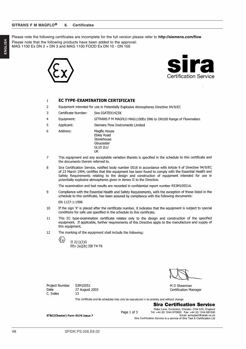
8.2 EC type examinationcertificate
8. Certificates
Please note the following certificates are incomplete for the full version please refer to http://siemens.com/flow

SITRANS F M MAGFLO®®®®®
47SFIDK.PS.026.E8.02
EN
GL
ISH
Appendix to certificate Number: Sira 03ATEX1442X.
8. Certificates
SITRANS F M MAGFLO®®®®®
48 SFIDK.PS.026.E8.02
EN
GL
ISH
8. Certificates
Please note the following certificates are incomplete for the full version please refer to http://siemens.com/flowPlease note that the following products have been added to the approval:MAG 1100 Ex DN 2 + DN 3 and MAG 1100 FOOD Ex DN 10 - DN 100

SITRANS F M MAGFLO®®®®®
49SFIDK.PS.026.E8.02
EN
GL
ISH
8. Certificates
Please note the following certificates are incomplete for the full version please refer to http://siemens.com/flow

SITRANS F M MAGFLO®®®®®
50 SFIDK.PS.026.E8.02
EN
GL
ISH
8. Certificates
Please note the following certificates are incomplete for the full version please refer to http://siemens.com/flow

SITRANS F M MAGFLO®®®®®
51SFIDK.PS.026.E8.02
EN
GL
ISHPlease note the following certificates are incomplete for the full version please refer to http://siemens.com/flow

We have checked the contents of this manual for agreement with the hardware andsoftware described. Since deviations cannot be precluded entirely, we cannot guaranteefull agreement. However, the data in this manual are reviewed regularly and anynecessary corrections included in subsequent editions. Suggestions for improvementare always welcomed.
Technical data subject to change without prior notice.
The reproduction, transmission or use of this document or its contents is not permitted withoutexpress written authority.Offenders will be liable for damages. All rights, including rights created by patent grant orregistration of a utility model or design, are reserved.
Copyright © Siemens AG 10.2006 All Rights Reserved
Siemens Flow Instruments A/SNordborgvej 81DK-6430 Nordborg
Order no.: FDK:521H1191-08Printed in: Denmark