instructions english deutsch sitrans f m magflo type mag 3100 - siemens … · siemens flow...
TRANSCRIPT

INSTRUCTIONSSITRANS F M MAGFLO®®®®®
Electromagnetic flowmetertype MAG 3100
083R
9159
083R
9159
SFIDK.PI.026.R2.52
Introduction
Order no. FDK-521H0970
s
Siemens Flow Instruments SITRANS F M MAGFLO® electromagnetic flowmeters consist of a sensorand a transmitter. These instructions only describe the sensor installation. For further information onthe transmitter installation, please refer to the SITRANS F M MAGFLO® handbook.
ENGLISHDEUTSCH
FRANÇAISDANSK
Technical Documentation (handbooks, instructions, manuals etc.) on the complete productrange SITRANS F can be found on the internet/intranet on the following links:
English: http://www4.ad.siemens.de/WW/view/en/10806951/133300
Dimensions and weight
A1) A1 B D1 L2) AS AWWA TC 3)
2129 E, C-207AS 4087 Class
PN PN PN PN PN Class Class Class D6, 10, 25 40 64 100 150 300 14-21,
16 35[mm] [inch] [mm] [mm] [mm] [mm] [mm] [mm] [mm] [mm] [mm] [mm] [mm] [mm] [mm] [mm] [kg]
25 1 187 338 59 104 200 200 200 - 260 200 200 200 1.2 540 1½ 197 348 82 124 200 200 200 - 280 200 200 200 1.2 850 2 205 356 72 139 200 200 200 276 300 200 200 200 1.2 965 2½ 212 363 72 154 200 200 200 320 350 200 272 200 1.2 1180 3 222 373 72 174 200 272 272 323 340 272 272 200 1.2 12
100 4 242 393 85 214 250 250 250 380 400 250 310 250 1.2 16125 5 255 406 85 239 250 250 250 420 450 250 335 250 1.2 19150 6 276 427 85 282 300 300 300 415 450 300 300 300 1.2 27200 8 304 455 137 338 350 350 350 480 530 350 350 350 1.2 40250 10 332 483 137 393 450 450 450 550 620 450 450 450 1.2 60300 12 357 508 137 444 500 500 500 600 680 500 500 500 1.6 80350 14 362 513 270 462 550 550 550 700 800 550 550 550 - 1.6 110400 16 387 538 270 512 600 600 600 750 - 600 600 600 - 1.6 125450 18 418 569 310 563 600 600 600 - - 600 640 600 - 1.6 175500 20 443 594 350 614 625 625 680 - - 680 730 625 - 1.6 200600 24 494 645 430 715 750 750 750 - - 820 860 750 - 1.6 300700 28 544 695 500 816 875 - - - - - - 875 875 2.0 350750 30 571 722 556 869 - - - - - - - 937 937 2.0 380
Weight 4)
EN 1092-1-2001 BS 1560/ANSI 16.5
Nominalsize
continued next page
MAG 3100, compact/separate

2
SITRANS F M MAGFLO®®®®® Electromagnetic flowmeter type MAG 3100
Installation, general Reading and operating the flowmeter is pos-sible under almost any installation condi-tions because the display can be oriented inrelation to the sensor. To ensure optimumflow measurement attention should be paidto the following:
The sensor must always be completely fullwith liquid.
Therefore avoid:• Installation at the highest point in the pipe
system• Installation in vertical pipes with free outlet
For partially filled pipes or pipes with down-ward flow and free outlet the flowmeter shouldbe located in a U-tube.
800 32 606 757 560 939 1000 - - - - - - 1000 1000 2.0 475900 36 653 804 630 1042 1125 - - - - - - 1125 1125 2.0 560
1000 40 704 906 670 1146 1250 - - - - - - 1250 1250 2.0 7001100 44 755 906 770 1248 1375 - - - - - - - - 2.0 12001200 48 810 961 792 1348 1500 - - - - - - 1500 1500 2.0 12501400 56 925 1076 1000 1675 1750 - - - - - - - - 3.0 17531500 50 972 1123 1020 1672 - - - - - - - 1875 1875 3.0 26001600 64 1025 1176 1130 1915 2000 - - - - - - - - 3.0 23411800 72 1123 1274 1250 1974 2250 - - - - - - - - 3.0 32532000 78 1223 1374 1375 2174 2500 - - - - - - - - 3.0 4060
1) 13 mm shorter with AISI terminal box (Ex and high temperature)2) When earthing flanges are used, the thickness of the earthing flange must be added to the built-in length3) TC = Type C grounding ring4) Weights are approx. and for PN 16 without transmitter
D = Outside diameter of flange, see flange tables
3
SITRANS F M MAGFLO®®®®® Electromagnetic flowmeter type MAG 3100
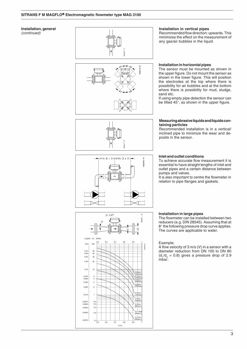
Installation in vertical pipesRecommended flow direction: upwards. Thisminimizes the effect on the measurement ofany gas/air bubbles in the liquid.
Installation in horizontal pipesThe sensor must be mounted as shown inthe upper figure. Do not mount the sensor asshown in the lower figure. This will positionthe electrodes at the top where there ispossibility for air bubbles and at the bottomwhere there is possibility for mud, sludge,sand etc.If using empty pipe detection the sensor canbe tilted 45°, as shown in the upper figure.
Measuring abrasive liquids and liquids con-taining particlesRecommended installation is in a vertical/inclined pipe to minimize the wear and de-posits in the sensor.
Inlet and outlet conditionsTo achieve accurate flow measurement it isessential to have straight lengths of inlet andoutlet pipes and a certain distance betweenpumps and valves.It is also important to centre the flowmeter inrelation to pipe flanges and gaskets.
Installation in large pipesThe flowmeter can be installed between tworeducers (e.g. DIN 28545). Assuming that at8° the following pressure drop curve applies.The curves are applicable to water.
Example:A flow velocity of 3 m/s (V) in a sensor with adiameter reduction from DN 100 to DN 80(d1/d2 = 0.8) gives a pressure drop of 2.9mbar.
Installation, general(continued)

4
SITRANS F M MAGFLO®®®®® Electromagnetic flowmeter type MAG 3100
Use an earth straps on one side.
Here an earthing flange is used, placed bet-ween flowmeter and the adjacent pipe flange.
Liner Suitablematerial earthing flange
All except Type CPTFEPTFE Type E
Electrically conductivepiping
Non-conductive piping
Potential equalisation Potential equalisation is carried out with thebuilt-in earthing electrodes.
Special attention must be given to systemswith cathodic protection.By compact mounting:The transmitter must be supplied through anisolation transformer. The terminal "PE" mustnever be connected.By remote mounting:The screen must only be connected at thesensor end via a 1.5 µF condensator. Thescreen must never be connected at both ends.By isolated sensor:If above mentioned connections are unaccept-able the sensor must be isolated from the pipework.
Cathodic protected piping
With earthing electrodes
Without earthing electrodes

5
SITRANS F M MAGFLO®®®®® Electromagnetic flowmeter type MAG 3100
The sensor must be mounted between twoflanges. Gaskets are only necessary when theflowmeter is installed with earthing flanges asthe liner is used in place of gaskets.
Installation
Inlet protection When measuring abrasive liquids the use offlowmeter inlet protection may be necessary.Here type C earthing flanges are used.
Effect of temperature andmaterial on workingpressure Flanges to EN 1092-1
Material Flange Temperature °°°°°Cgroup rating −20 50 1001C1 (A105) PN 6 6.0 5.8 5.6
PN10 10.0 9.7 9.4PN16 16.0 15.5 15.0PN 25 25.0 24.2 23.4PN 40 40.0 38.7 37.5PN 63 63.0 63.0 63.0PN 100 100.0 100.0 100.0
2C1 (304) PN 6 5.5 5.3 4.5PN 10 9.1 8.8 7.5PN 16 14.7 14.2 12.1PN 25 23.0 22.1 18.9PN 40 36.8 35.4 30.3PN 63 57.9 55.8 47.7PN 100 91.9 88.6 75.7
2C2 (316) PN 6 5.5 5.3 4.6PN 10 9.1 8.9 7.8PN 16 14.7 14.3 12.5PN 25 23.0 22.3 19.5PN 40 36.8 35.6 31.3PN 63 57.9 56.1 49.2PN 100 91.9 89.1 78.1
Metric (Pressures in bar)
The above tables show the effect that an increase of temperature or change of material haveon the maximum working pressure of the flange. The values are independent of nominal size.For intermediate temperatures use value from nearest higher temperature.
ExampleFor a PN 16 flange in 2C2 (316) material at 80 degrees the maximum working pressure shouldbe taken as 12.5 bar.
Flanges to EN 1092-1Material Flange Temperature °°°°°Fgroup rating −5 122 212ASTM A105 PN 6 87 84 81
PN 10 145 141 136PN 16 232 225 218PN 25 363 351 339PN 40 580 561 544PN 63 914 914 914PN 100 1450 1450 1450
ASTM A240 PN 6 80 77 65304 PN 10 132 128 109
PN 16 213 206 175PN 25 334 320 274PN 40 534 513 439PN 63 840 809 692PN 100 1333 1285 1098
ASTM A240 PN 6 80 77 67316 PN 10 132 129 113
PN 16 213 207 181PN 25 334 323 283PN 40 534 516 454PN 63 840 813 713PN 100 1333 1292 1132
Imperial (Pressures in Psi)

6
SITRANS F M MAGFLO®®®®® Electromagnetic flowmeter type MAG 3100
Maximum allowable torquesNominal Maximum torque
size PN 6 PN 10 PN 16 PN 25 PN 40 PN 63 PN 100mm Inch Nm F/Lbs Nm F/Lbs Nm F/Lbs Nm F/Lbs Nm F/Lbs Nm F/Lbs Nm F/Lbs15 ½” N/A N/A N/A N/A N/A N/A N/A N/A 10 7 N/A N/A N/A N/A25 1" N/A N/A N/A N/A N/A N/A N/A N/A 16 12 N/A N/A 50 3740 1½” N/A N/A N/A N/A N/A N/A N/A N/A 34 25 N/A N/A 100 7450 2" N/A N/A N/A N/A N/A N/A N/A N/A 46 34 90 66 140 10365 2½” 10 7 N/A N/A 25 18 N/A N/A 34 25 64 47 110 8180 3" 25 18 N/A N/A 25 18 N/A N/A 42 31 82 61 130 96100 4" 25 18 N/A N/A 25 18 N/A N/A 72 53 136 100 190 140125 5" 25 18 N/A N/A 32 24 N/A N/A 114 84 200 148 250 185150 6" 25 18 N/A N/A 50 37 N/A N/A 144 106 275 203 210 155200 8" 25 18 50 37 52 38 105 77 185 137 330 244 400 295250 10" 25 18 50 37 88 65 160 118 300 221 500 369 550 406300 12" 50 37 62 46 117 86 170 125 320 236 525 387 700 517350 14" 50 37 60 44 120 89 240 177 450 332 750 554 1200 886400 16" 50 37 88 65 170 125 330 244 650 480 1100 812 N/A N/A450 18" 56 41 92 68 170 125 320 236 570 421 N/A N/A N/A N/A500 20" 53 39 103 76 230 170 390 288 740 546 N/A N/A N/A N/A600 24" 81 60 161 119 350 258 560 413 1220 900 N/A N/A N/A N/A700 28" 100 74 200 148 304 224 N/A N/A N/A N/A N/A N/A N/A N/A800 32" 140 103 274 202 386 285 N/A N/A N/A N/A N/A N/A N/A N/A900 36" 172 127 288 213 408 301 N/A N/A N/A N/A N/A N/A N/A N/A1000 40" 180 133 382 282 546 403 N/A N/A N/A N/A N/A N/A N/A N/A1200 48" 252 186 395 292 731 539 N/A N/A N/A N/A N/A N/A N/A N/A1400 54" 330 244 503 371 736 543 N/A N/A N/A N/A N/A N/A N/A N/A1600 66" 380 280 684 505 913 674 N/A N/A N/A N/A N/A N/A N/A N/A1800 72" 382 282 771 569 937 692 N/A N/A N/A N/A N/A N/A N/A N/A2000 78" 432 319 867 640 1128 832 N/A N/A N/A N/A N/A N/A N/A N/A
Torque calculations All values are theoretical and are calculated making the following assumptions:
1. All bolts are new and material selection is according to EN 1515-1 table 2
2. Gasket material not exceeding 75 shore A durometer is used between the flowmeter andmating flanges
3. All bolts are galvanized and adequately lubricated
4. The values are calculated for use with carbon steel flanges
5. Flowmeter and mating flanges are correctly aligned
Standard bolts must be well lubricated andtightened evenly around the gasket. Leakage/damage to the flowmeter or piping may arise ifbolts are overtightened.
Tightening
7
SITRANS F M MAGFLO®®®®® Electromagnetic flowmeter type MAG 3100
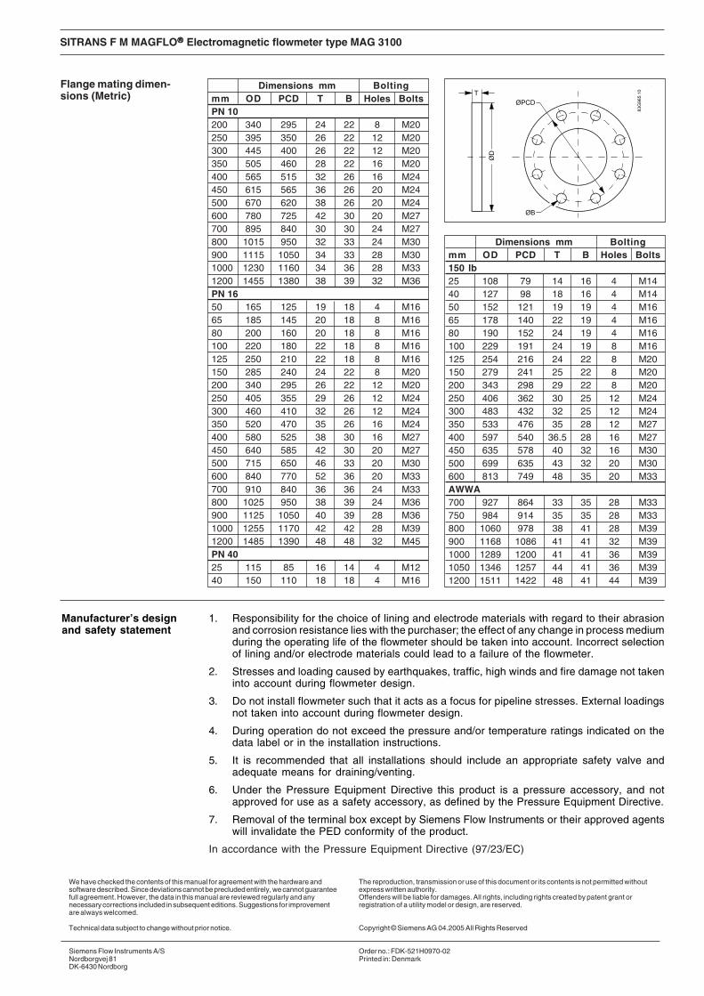
Flange mating dimen-sions (Metric)
Dimensions mm Boltingmm OD PCD T B Holes BoltsPN 10200 340 295 24 22 8 M20250 395 350 26 22 12 M20300 445 400 26 22 12 M20350 505 460 28 22 16 M20400 565 515 32 26 16 M24450 615 565 36 26 20 M24500 670 620 38 26 20 M24600 780 725 42 30 20 M27700 895 840 30 30 24 M27800 1015 950 32 33 24 M30900 1115 1050 34 33 28 M301000 1230 1160 34 36 28 M331200 1455 1380 38 39 32 M36PN 1650 165 125 19 18 4 M1665 185 145 20 18 8 M1680 200 160 20 18 8 M16100 220 180 22 18 8 M16125 250 210 22 18 8 M16150 285 240 24 22 8 M20200 340 295 26 22 12 M20250 405 355 29 26 12 M24300 460 410 32 26 12 M24350 520 470 35 26 16 M24400 580 525 38 30 16 M27450 640 585 42 30 20 M27500 715 650 46 33 20 M30600 840 770 52 36 20 M33700 910 840 36 36 24 M33800 1025 950 38 39 24 M36900 1125 1050 40 39 28 M361000 1255 1170 42 42 28 M391200 1485 1390 48 48 32 M45PN 4025 115 85 16 14 4 M1240 150 110 18 18 4 M16
Dimensions mm Boltingmm OD PCD T B Holes Bolts150 lb25 108 79 14 16 4 M1440 127 98 18 16 4 M1450 152 121 19 19 4 M1665 178 140 22 19 4 M1680 190 152 24 19 4 M16100 229 191 24 19 8 M16125 254 216 24 22 8 M20150 279 241 25 22 8 M20200 343 298 29 22 8 M20250 406 362 30 25 12 M24300 483 432 32 25 12 M24350 533 476 35 28 12 M27400 597 540 36.5 28 16 M27450 635 578 40 32 16 M30500 699 635 43 32 20 M30600 813 749 48 35 20 M33AWWA700 927 864 33 35 28 M33750 984 914 35 35 28 M33800 1060 978 38 41 28 M39900 1168 1086 41 41 32 M391000 1289 1200 41 41 36 M391050 1346 1257 44 41 36 M391200 1511 1422 48 41 44 M39
1. Responsibility for the choice of lining and electrode materials with regard to their abrasionand corrosion resistance lies with the purchaser; the effect of any change in process mediumduring the operating life of the flowmeter should be taken into account. Incorrect selectionof lining and/or electrode materials could lead to a failure of the flowmeter.
2. Stresses and loading caused by earthquakes, traffic, high winds and fire damage not takeninto account during flowmeter design.
3. Do not install flowmeter such that it acts as a focus for pipeline stresses. External loadingsnot taken into account during flowmeter design.
4. During operation do not exceed the pressure and/or temperature ratings indicated on thedata label or in the installation instructions.
5. It is recommended that all installations should include an appropriate safety valve andadequate means for draining/venting.
6. Under the Pressure Equipment Directive this product is a pressure accessory, and notapproved for use as a safety accessory, as defined by the Pressure Equipment Directive.
7. Removal of the terminal box except by Siemens Flow Instruments or their approved agentswill invalidate the PED conformity of the product.
In accordance with the Pressure Equipment Directive (97/23/EC)
Manufacturer’s designand safety statement
We have checked the contents of this manual for agreement with the hardware andsoftware described. Since deviations cannot be precluded entirely, we cannot guaranteefull agreement. However, the data in this manual are reviewed regularly and anynecessary corrections included in subsequent editions. Suggestions for improvementare always welcomed.
Technical data subject to change without prior notice.
The reproduction, transmission or use of this document or its contents is not permitted withoutexpress written authority.Offenders will be liable for damages. All rights, including rights created by patent grant orregistration of a utility model or design, are reserved.
Copyright © Siemens AG 04.2005 All Rights Reserved
Siemens Flow Instruments A/SNordborgvej 81DK-6430 Nordborg
Order no.: FDK-521H0970-02Printed in: Denmark

SITRANS F M MAGFLO®®®®®
Magnetisch induktiver DurchflussmesserTyp MAG 3100
DEUTSCH08
3R91
59
083R
9159
SFIDK.PI.026.R2.52
Siemens Flow Instruments SITRANS F M MAGFLO® magnetisch-induktive Durchflussmesser bestehenaus einem Messaufnehmer und einem Messumformer. Diese Instruktion beschreibt nur die Montagedes Messaufnehmers. Für weitere Informationen über die Montage des Messumformers, siehe bittedas SITRANS F M MAGFLO® Produkt-handbuch.
Einführung
s INSTRUCTIONS
Technische Unterlagen (Handbücher, Instruktionen, Betriebsanleitung usw.) deskompletten Warenangebotes von SITRANS F sind auf dem Internet/Intranet unter folgendenLinks verfügbar
Deutsch: http://www4.ad.siemens.de/WW/view/de/10806951/133300
Abmessungen undGewichte
Fortsetzung nächste Seite
MAG 3100, kompakte/getrennte Montage
A1) A1 B D1 L2) AS AWWA TC 3)
2129 E, C-207AS 4087 Class
PN PN PN PN PN Class Class Class D6, 10, 25 40 64 100 150 300 14-21,
16 35[mm] [inch] [mm] [mm] [mm] [mm] [mm] [mm] [mm] [mm] [mm] [mm] [mm] [mm] [mm] [mm] [kg]
25 1 187 338 59 104 200 200 200 - 260 200 200 200 1,2 540 1½ 197 348 82 124 200 200 200 - 280 200 200 200 1,2 850 2 205 356 72 139 200 200 200 276 300 200 200 200 1,2 965 2½ 212 363 72 154 200 200 200 320 350 200 272 200 1,2 1180 3 222 373 72 174 200 272 272 323 340 272 272 200 1,2 12
100 4 242 393 85 214 250 250 250 380 400 250 310 250 1,2 16125 5 255 406 85 239 250 250 250 420 450 250 335 250 1,2 19150 6 276 427 85 282 300 300 300 415 450 300 300 300 1,2 27200 8 304 455 137 338 350 350 350 480 530 350 350 350 1,2 40250 10 332 483 137 393 450 450 450 550 620 450 450 450 1,2 60300 12 357 508 137 444 500 500 500 600 680 500 500 500 1,6 80350 14 362 513 270 462 550 550 550 700 800 550 550 550 - 1,6 110400 16 387 538 270 512 600 600 600 750 - 600 600 600 - 1,6 125450 18 418 569 310 563 600 600 600 - - 600 640 600 - 1,6 175500 20 443 594 350 614 625 625 680 - - 680 730 625 - 1,6 200600 24 494 645 430 715 750 750 750 - - 820 860 750 - 1,6 300700 28 544 695 500 816 875 - - - - - - 875 875 2,0 350750 30 571 722 556 869 - - - - - - - 937 937 2,0 380
Gewicht 4)
EN 1092-1-2001 BS 1560/ANSI 16.5
Nennweite
9
SITRANS F M MAGFLO®®®®® Magnetisch induktiver Durchflussmesser Typ MAG 3100
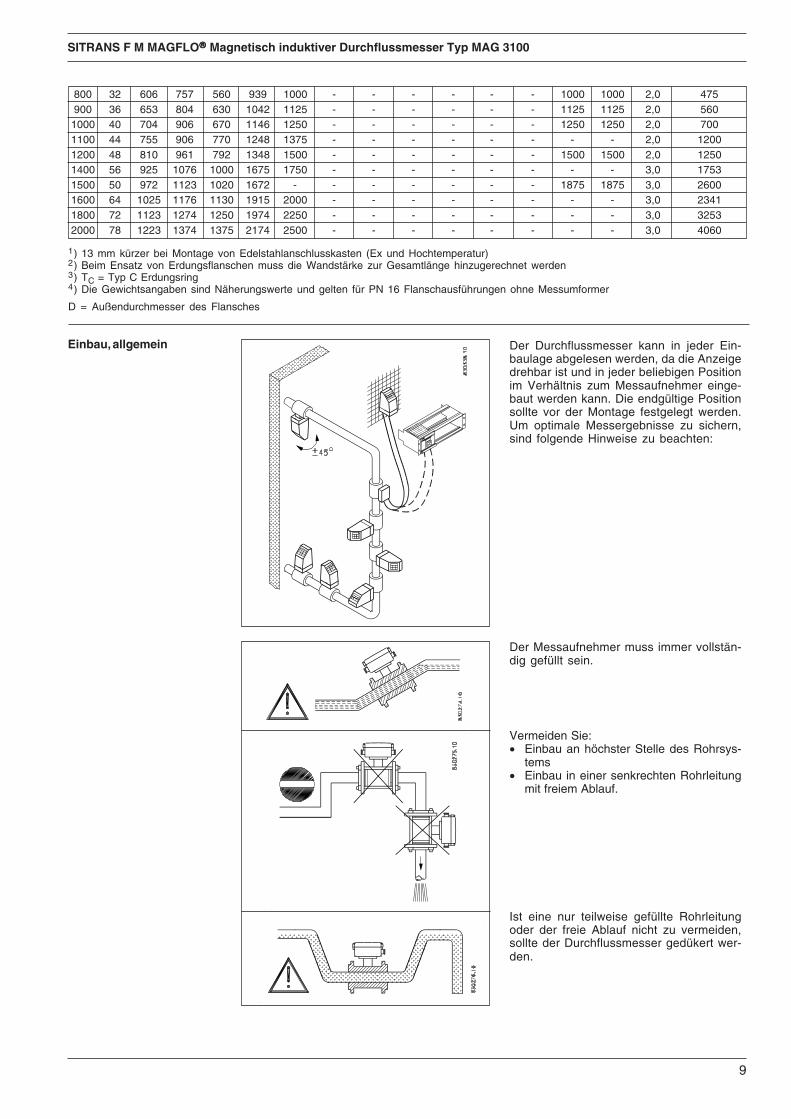
Einbau, allgemein Der Durchflussmesser kann in jeder Ein-baulage abgelesen werden, da die Anzeigedrehbar ist und in jeder beliebigen Positionim Verhältnis zum Messaufnehmer einge-baut werden kann. Die endgültige Positionsollte vor der Montage festgelegt werden.Um optimale Messergebnisse zu sichern,sind folgende Hinweise zu beachten:
Der Messaufnehmer muss immer vollstän-dig gefüllt sein.
Vermeiden Sie:• Einbau an höchster Stelle des Rohrsys-
tems• Einbau in einer senkrechten Rohrleitung
mit freiem Ablauf.
Ist eine nur teilweise gefüllte Rohrleitungoder der freie Ablauf nicht zu vermeiden,sollte der Durchflussmesser gedükert wer-den.
1) 13 mm kürzer bei Montage von Edelstahlanschlusskasten (Ex und Hochtemperatur)2) Beim Ensatz von Erdungsflanschen muss die Wandstärke zur Gesamtlänge hinzugerechnet werden3) TC = Typ C Erdungsring4) Die Gewichtsangaben sind Näherungswerte und gelten für PN 16 Flanschausführungen ohne Messumformer
D = Außendurchmesser des Flansches
800 32 606 757 560 939 1000 - - - - - - 1000 1000 2,0 475900 36 653 804 630 1042 1125 - - - - - - 1125 1125 2,0 5601000 40 704 906 670 1146 1250 - - - - - - 1250 1250 2,0 7001100 44 755 906 770 1248 1375 - - - - - - - - 2,0 12001200 48 810 961 792 1348 1500 - - - - - - 1500 1500 2,0 12501400 56 925 1076 1000 1675 1750 - - - - - - - - 3,0 17531500 50 972 1123 1020 1672 - - - - - - - 1875 1875 3,0 26001600 64 1025 1176 1130 1915 2000 - - - - - - - - 3,0 23411800 72 1123 1274 1250 1974 2250 - - - - - - - - 3,0 32532000 78 1223 1374 1375 2174 2500 - - - - - - - - 3,0 4060

10
SITRANS F M MAGFLO®®®®® Magnetisch induktiver Durchflussmesser Typ MAG 3100
Einbau in einer waagerechten RohrleitungDer Messaufnehmer ist wie nebenstehendin der oberen Abbildung gezeigt zu montie-ren. Wegen der Lage der Elektroden oben(hier können Luftblasen entstehen) undunten (eventuelle Ansammlung vonSchlamm, Sand usw.) darf die Montage nichtwie in der unteren Abbildung gezeigt erfol-gen. Wird die Leerlaufüberwachung akti-viert, um einen leeren Messaufnehmer zumelden, dürfen Messaufnehmer und Mess-umformer nicht mehr als 45° gedreht wer-den, siehe obere Abbildung.
Messen von verunreinigten bzw. abrasivenMedienIn diesem Fall wird der Einbau in einer senk-rechten bzw. schrägen Rohrleitung empfoh-len, um Verschleiß bzw. Ablagerungen soweit wie möglich zu vermeiden.
Ein- und AuslaufGenaue Messwerte können nur dann erzieltwerden, wenn ausreichend große geradeEin- und Auslaufstrecken sowie genügenderAbstand nach Pumpen, Ventilen o. ä. einge-halten werden.Außerdem muss der Durchflussmesser mit-tig zu den Flanschen und Dichtungen desRohrsystems eingebaut werden.
Einbau, allgemein(Fortsetzung)
Einbau in einer Rohrleitung mit großemDurchmesserFalls notwendig, kann der Durchflussmesserauch zwischen zwei Reduzierstücken, z. B.nach DIN 28545 eingebaut werden. Unterder Voraussetzung, daß α < 8° gilt nebenste-hendes Druckverlustdiagramm (Medium:Wasser).
Beispiel:Eine Durchflussgeschwindigkeit von V = 3m/s in einem Messaufnehmer mit einerDurchmesserreduktion von DN 100 auf DN80 (d1/d2 = 0,8) verursacht einen Druckabfallvon 2,9 mbar.
Einbau in einer senkrechten RohrleitungEmpfohlene Strömungsrichtung: von untennach oben. Dadurch werden ungenaueMessergebnisse, verursacht durch Gas- bzw.Luftblasen im Medium, vermieden.

11
SITRANS F M MAGFLO®®®®® Magnetisch induktiver Durchflussmesser Typ MAG 3100
Potentialausgleich Der Potentialausgleich erfolgt über die Er-dungselektroden des Messaufnehmers MAG3100.
Verwenden Sie auf einer Seite ein Erdungs-kabel.
Hier wird ein Erdungsflansch eingesetzt, derzwischen dem Durchflussmesser und demanliegenden Rohrflansch eingebaut wird.
Bei Rohrleitungen mit katodischem Schutzist besondere Sorgfalt geboten.Bei kompaktem Einbau:Der Messumformer muss über einenTrenntransformator gespeist werden. DerAnschluß „PE“ darf niemals angeschlossenwerden.Bei getrenntem Einbau:Die Abschirmung muss man über einen 1,5µF Kondensator mit demMessaufnehmerende verbinden. DieAbschirmung darf nie an beide Endenangeschlossen werden.Bei isoliertem Einbau:Falls die obengenannten Anschlüsse nichtakzeptierbar sind, muss der Messaufnehmervon der Rohrleitung isoliert werden.
Auskleidungs- passenderwerkstoff Erdungsring
alle außer Type CPTFEPTFE Type E
Elektrisch leitendeRohrleitung
Elektrisch nicht leitendeRohrleitung
5.3KathodischerRohrleitungsschutz
Mit intergrierten Erdungselektroden
Ohne intergrierten Erdungselektroden
12
SITRANS F M MAGFLO®®®®® Magnetisch induktiver Durchflussmesser Typ MAG 3100
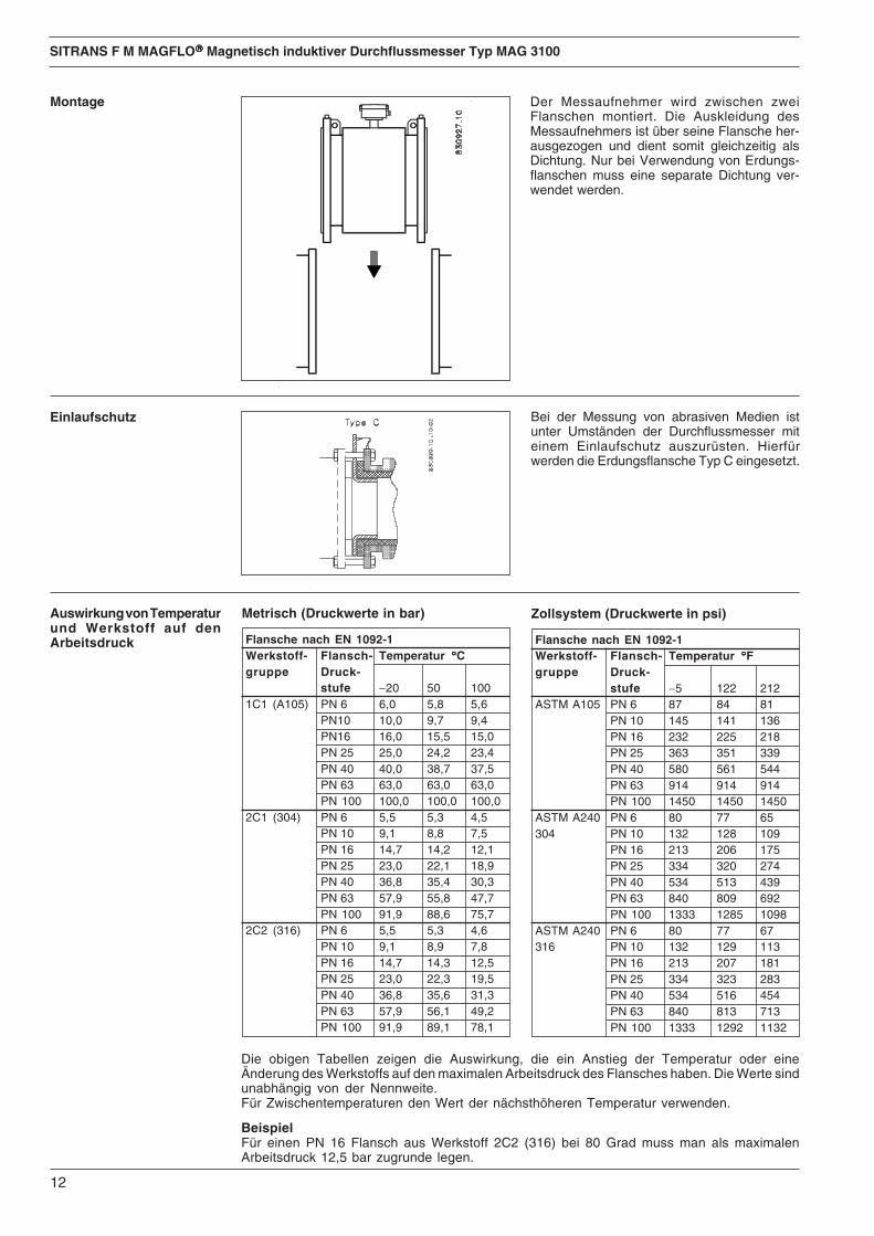
Der Messaufnehmer wird zwischen zweiFlanschen montiert. Die Auskleidung desMessaufnehmers ist über seine Flansche her-ausgezogen und dient somit gleichzeitig alsDichtung. Nur bei Verwendung von Erdungs-flanschen muss eine separate Dichtung ver-wendet werden.
Montage
Einlaufschutz Bei der Messung von abrasiven Medien istunter Umständen der Durchflussmesser miteinem Einlaufschutz auszurüsten. Hierfürwerden die Erdungsflansche Typ C eingesetzt.
Auswirkung von Temperaturund Werkstoff auf denArbeitsdruck Flansche nach EN 1092-1
Werkstoff- Flansch- Temperatur °°°°°Cgruppe Druck-
stufe −20 50 1001C1 (A105) PN 6 6,0 5,8 5,6
PN10 10,0 9,7 9,4PN16 16,0 15,5 15,0PN 25 25,0 24,2 23,4PN 40 40,0 38,7 37,5PN 63 63,0 63,0 63,0PN 100 100,0 100,0 100,0
2C1 (304) PN 6 5,5 5,3 4,5PN 10 9,1 8,8 7,5PN 16 14,7 14,2 12,1PN 25 23,0 22,1 18,9PN 40 36,8 35,4 30,3PN 63 57,9 55,8 47,7PN 100 91,9 88,6 75,7
2C2 (316) PN 6 5,5 5,3 4,6PN 10 9,1 8,9 7,8PN 16 14,7 14,3 12,5PN 25 23,0 22,3 19,5PN 40 36,8 35,6 31,3PN 63 57,9 56,1 49,2PN 100 91,9 89,1 78,1
Metrisch (Druckwerte in bar)
Die obigen Tabellen zeigen die Auswirkung, die ein Anstieg der Temperatur oder eineÄnderung des Werkstoffs auf den maximalen Arbeitsdruck des Flansches haben. Die Werte sindunabhängig von der Nennweite.Für Zwischentemperaturen den Wert der nächsthöheren Temperatur verwenden.
BeispielFür einen PN 16 Flansch aus Werkstoff 2C2 (316) bei 80 Grad muss man als maximalenArbeitsdruck 12,5 bar zugrunde legen.
Flansche nach EN 1092-1Werkstoff- Flansch- Temperatur °°°°°Fgruppe Druck-
stufe −5 122 212ASTM A105 PN 6 87 84 81
PN 10 145 141 136PN 16 232 225 218PN 25 363 351 339PN 40 580 561 544PN 63 914 914 914PN 100 1450 1450 1450
ASTM A240 PN 6 80 77 65304 PN 10 132 128 109
PN 16 213 206 175PN 25 334 320 274PN 40 534 513 439PN 63 840 809 692PN 100 1333 1285 1098
ASTM A240 PN 6 80 77 67316 PN 10 132 129 113
PN 16 213 207 181PN 25 334 323 283PN 40 534 516 454PN 63 840 813 713PN 100 1333 1292 1132
Zollsystem (Druckwerte in psi)

13
SITRANS F M MAGFLO®®®®® Magnetisch induktiver Durchflussmesser Typ MAG 3100
Flanschenbolzen gut einfetten und gleichmäßigum die Dichtungsfläche anziehen. Ein zu hohesoder "schiefes" Anziehen kann Undichtigkeitenbzw. Schäden am Durchflussmesser und ander Rohrleitung verursachen.Die Tabelle ist gültig bei einem Druck bis zumax. 16 bar.
Anzugsmoment
Drehmoment-Berechnungen
Alle Werte sind theoretisch und werden unter folgenden Annahmen berechnet:
1) Alle Bolzen sind neu und die Werkstoffauswahl entspricht EN 1515-1 Tabelle 2
2) Dichtungswerkstoff von höchstens 75 Shore A Härte wird zwischen dem Durchflussmesserund den zugehörigen Flanschen verwendet
3) Alle Bolzen sind verzinkt und entsprechend eingefettet
4) Die Werte sind für den Einsatz mit Kohlenstoffstahl-Flanschen berechnet
5) Durchflussmesser und zugehörige Flansche sind einwandfrei ausgerichtet
Maximal zulässige DrehmomenteNennweite Maximales Drehmoment
PN 6 PN 10 PN 16 PN 25 PN 40 PN 63 PN 100mm Inch Nm F/Lbs Nm F/Lbs Nm F/Lbs Nm F/Lbs Nm F/Lbs Nm F/Lbs Nm F/Lbs15 ½” N/A N/A N/A N/A N/A N/A N/A N/A 10 7 N/A N/A N/A N/A25 1" N/A N/A N/A N/A N/A N/A N/A N/A 16 12 N/A N/A 50 3740 1½” N/A N/A N/A N/A N/A N/A N/A N/A 34 25 N/A N/A 100 7450 2" N/A N/A N/A N/A N/A N/A N/A N/A 46 34 90 66 140 10365 2½” 10 7 N/A N/A 25 18 N/A N/A 34 25 64 47 110 8180 3" 25 18 N/A N/A 25 18 N/A N/A 42 31 82 61 130 96100 4" 25 18 N/A N/A 25 18 N/A N/A 72 53 136 100 190 140125 5" 25 18 N/A N/A 32 24 N/A N/A 114 84 200 148 250 185150 6" 25 18 N/A N/A 50 37 N/A N/A 144 106 275 203 210 155200 8" 25 18 50 37 52 38 105 77 185 137 330 244 400 295250 10" 25 18 50 37 88 65 160 118 300 221 500 369 550 406300 12" 50 37 62 46 117 86 170 125 320 236 525 387 700 517350 14" 50 37 60 44 120 89 240 177 450 332 750 554 1200 886400 16" 50 37 88 65 170 125 330 244 650 480 1100 812 N/A N/A450 18" 56 41 92 68 170 125 320 236 570 421 N/A N/A N/A N/A500 20" 53 39 103 76 230 170 390 288 740 546 N/A N/A N/A N/A600 24" 81 60 161 119 350 258 560 413 1220 900 N/A N/A N/A N/A700 28" 100 74 200 148 304 224 N/A N/A N/A N/A N/A N/A N/A N/A800 32" 140 103 274 202 386 285 N/A N/A N/A N/A N/A N/A N/A N/A900 36" 172 127 288 213 408 301 N/A N/A N/A N/A N/A N/A N/A N/A1000 40" 180 133 382 282 546 403 N/A N/A N/A N/A N/A N/A N/A N/A1200 48" 252 186 395 292 731 539 N/A N/A N/A N/A N/A N/A N/A N/A1400 54" 330 244 503 371 736 543 N/A N/A N/A N/A N/A N/A N/A N/A1600 66" 380 280 684 505 913 674 N/A N/A N/A N/A N/A N/A N/A N/A1800 72" 382 282 771 569 937 692 N/A N/A N/A N/A N/A N/A N/A N/A2000 78" 432 319 867 640 1128 832 N/A N/A N/A N/A N/A N/A N/A N/A
14
SITRANS F M MAGFLO®®®®® Magnetisch induktiver Durchflussmesser Typ MAG 3100
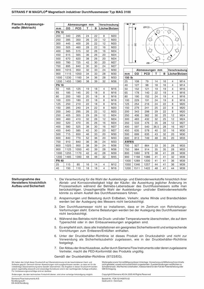
Flansch-Anpassungs-maße (Metrisch)
Abmessungen mm Verschraubungmm OD PCD T B Löcher BolzenPN 10200 340 295 24 22 8 M20250 395 350 26 22 12 M20300 445 400 26 22 12 M20350 505 460 28 22 16 M20400 565 515 32 26 16 M24450 615 565 36 26 20 M24500 670 620 38 26 20 M24600 780 725 42 30 20 M27700 895 840 30 30 24 M27800 1015 950 32 33 24 M30900 1115 1050 34 33 28 M301000 1230 1160 34 36 28 M331200 1455 1380 38 39 32 M36PN 1650 165 125 19 18 4 M1665 185 145 20 18 8 M1680 200 160 20 18 8 M16100 220 180 22 18 8 M16125 250 210 22 18 8 M16150 285 240 24 22 8 M20200 340 295 26 22 12 M20250 405 355 29 26 12 M24300 460 410 32 26 12 M24350 520 470 35 26 16 M24400 580 525 38 30 16 M27450 640 585 42 30 20 M27500 715 650 46 33 20 M30600 840 770 52 36 20 M33700 910 840 36 36 24 M33800 1025 950 38 39 24 M36900 1125 1050 40 39 28 M361000 1255 1170 42 42 28 M391200 1485 1390 48 48 32 M45PN 4025 115 85 16 14 4 M1240 150 110 18 18 4 M16
Abmessungen mm Verschraubungmm OD PCD T B Löcher Bolzen150 lb25 108 79 14 16 4 M1440 127 98 18 16 4 M1450 152 121 19 19 4 M1665 178 140 22 19 4 M1680 190 152 24 19 4 M16100 229 191 24 19 8 M16125 254 216 24 22 8 M20150 279 241 25 22 8 M20200 343 298 29 22 8 M20250 406 362 30 25 12 M24300 483 432 32 25 12 M24350 533 476 35 28 12 M27400 597 540 36.5 28 16 M27450 635 578 40 32 16 M30500 699 635 43 32 20 M30600 813 749 48 35 20 M33AWWA700 927 864 33 35 28 M33750 984 914 35 35 28 M33800 1060 978 38 41 28 M39900 1168 1086 41 41 32 M391000 1289 1200 41 41 36 M391050 1346 1257 44 41 36 M391200 1511 1422 48 41 44 M39
1. Die Verantwortung für die Wahl der Auskleidungs- und Elektrodenwerkstoffe hinsichtich ihrerAbrieb- und Korrosionsfestigkeit trägt der Käufer; die Auswirkung jeglicher Änderung imProzessmedium während der Betriebs-Lebensdauer des Durchflussmessers sollte manberücksichtigen. Unsachgemäße Wahl der Auskleidungs- und/oder Elektrodenwerkstoffekönnte zu einem Ausfall des Durchflussmessers führen.
2. Anspannungen und Belastung durch Erdbeben, Verkehr, starke Winde und Brandschädenwerden bei der Auslegung des Messers nicht berücksichtigt.
3. Den Durchflussmesser nicht so installieren, dass er im Zentrum von Rohrleitungs-Verformungen steht. Externe Belastungen werden bei der Auslegung des Durchflussmessernicht berücksichtigt.
4. Während des Betriebs nicht die Druck- und/oder Temperaturwerte überschreiten, die auf demTypenschild oder in den Einbauanweisungen angegeben sind.
5. Es empfiehlt sich, dass alle Installationen ein geeignetes Sicherheitsventil und entsprechendeVorrichtungen zum Entleeren/Entlüften enthalten.
6. Unter der Druckbehälter-Richtlinie ist dieses Produkt ein Druckzubehör und nicht zurVerwendung als Sicherheitszubehör zugelassen, wie in der Druckbehälter-Richtliniefestgelegt.
7. Der Abbau der Anschlussdose, außer durch Siemens Flow Instruments oder deren zugelasseneVertreter, macht die PED-Konformität des Produkts ungültig.
Gemäß der Druckbehälter-Richtlinie (97/23/EG).
Stellungnahme desHerstellers hinsichtlichAufbau und Sicherheit
Wir haben den Inhalt dieser Druckschrift auf Übereinstimmung mit der beschriebenen Hard- undSoftware geprüft. Dennoch können Abweichungen nicht ausgeschlossen werden, so dass wir für dievollständige Übereinstimmung keine Gewähr übernehmen. Die Angaben in dieser Druckschrift werdenjedoch regelmäßig überprüft und notwendige Korrekturen sind in der nachfolgenden Auflage enthalten.Für Verbesserungsvorschläge sind wir dankbar.
Änderungen, die dem technischen Fortschritt dienen, sind ohne vorherige Ankündigung möglich.
Weitergabe sowie Vervielfältigung dieser Unterlage, Verwertung und Mitteilung ihres Inhaltsnicht gestattet, soweit nicht ausdrücklich zugestanden. Zuwiderhandlungen verpflichten zuSchadenersatz. Alle Rechte vorbehalten, insbesondere für den Fall der Patenterteilung oderGM-Eintragung.
Copyright © Siemens AG 04.2005 All Rights Reserved
Siemens Flow Instruments A/SNordborgvej 81DK-6430 Nordborg
Bestell-Nr.: FDK-521H0970-02Gedruckt in : Denmark

INSTRUCTIONSSITRANS F M MAGFLO®®®®®
Débitmètre à induction magnétiquetype MAG 3100
FRANÇAIS08
3R91
59
083R
9159
Siemens Flow Instruments SITRANS F M MAGFLO® débitmètres à induction magnétique consistent d'unetête de mesure et d'un convertisseur de signaux. Cette instruction seulement concerne le montage de latête de mesure. Pour plus d'informations sur le montage du convertisseur de signaux, voir le Manuel.
Présentation
SFIDK.PI.026.R2.52
s
Les Documentations techniques (manuels, instructions, etc...) de la gamme de produitsSITRANS F peuvent être trouvées sur internet/intranet avec le lien suivant :
Francais: http://www4.ad.siemens.de/WW/view/fr/10806951/133300
suite à la page suivante
MAG 3100, montage compact/séparéDimensions et poids
A1) A1 B D1 L2) AS AWWA TC 3)
2129 E, C-207AS 4087 Class
PN PN PN PN PN Class Class Class D6, 10, 25 40 64 100 150 300 14-21,
16 35[mm] [inch] [mm] [mm] [mm] [mm] [mm] [mm] [mm] [mm] [mm] [mm] [mm] [mm] [mm] [mm] [kg]
25 1 187 338 59 104 200 200 200 - 260 200 200 200 1,2 540 1½ 197 348 82 124 200 200 200 - 280 200 200 200 1,2 850 2 205 356 72 139 200 200 200 276 300 200 200 200 1,2 965 2½ 212 363 72 154 200 200 200 320 350 200 272 200 1,2 1180 3 222 373 72 174 200 272 272 323 340 272 272 200 1,2 12
100 4 242 393 85 214 250 250 250 380 400 250 310 250 1,2 16125 5 255 406 85 239 250 250 250 420 450 250 335 250 1,2 19150 6 276 427 85 282 300 300 300 415 450 300 300 300 1,2 27200 8 304 455 137 338 350 350 350 480 530 350 350 350 1,2 40250 10 332 483 137 393 450 450 450 550 620 450 450 450 1,2 60300 12 357 508 137 444 500 500 500 600 680 500 500 500 1,6 80350 14 362 513 270 462 550 550 550 700 800 550 550 550 - 1,6 110400 16 387 538 270 512 600 600 600 750 - 600 600 600 - 1,6 125450 18 418 569 310 563 600 600 600 - - 600 640 600 - 1,6 175500 20 443 594 350 614 625 625 680 - - 680 730 625 - 1,6 200600 24 494 645 430 715 750 750 750 - - 820 860 750 - 1,6 300700 28 544 695 500 816 875 - - - - - - 875 875 2,0 350750 30 571 722 556 869 - - - - - - - 937 937 2,0 380
Poids 4)
EN 1092-1-2001 BS 1560/ANSI 16.5
Dimensionsnominales
16
SITRANS F M MAGFLO®®®®® Débitmètre à induction magnétique type MAG 3100
1) 13 mm plus court avec la boîte de connexions AISI (Ex et haute température)2) En cas d’utilisation de brides de mise à la terre, ajouter l’épaisseur de la bride à la longueur normalisée3) TC = bride de mise à la terre de type C4) Les poids sont approximatifs et correspondent à PN 16 sans convertisseur de signaux
D = diamètre extérieur de la bride, voir tables correspondantes
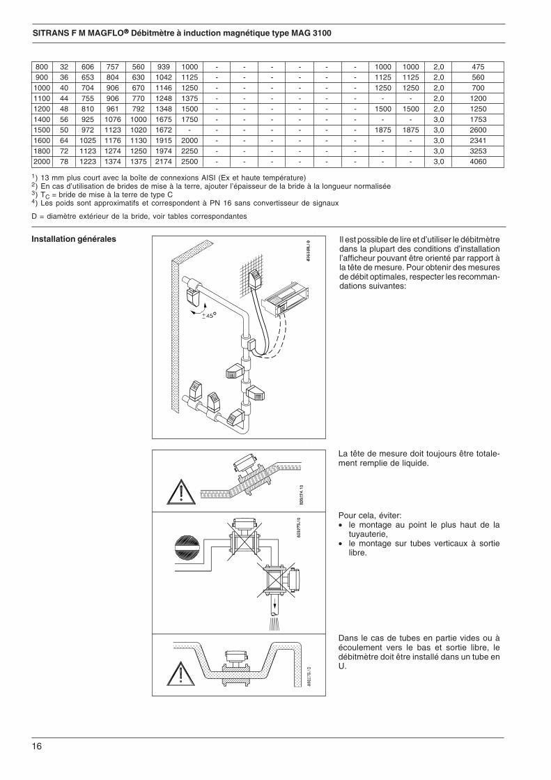
Installation générales Il est possible de lire et d’utiliser le débitmètredans la plupart des conditions d’installationl’afficheur pouvant être orienté par rapport àla tête de mesure. Pour obtenir des mesuresde débit optimales, respecter les recomman-dations suivantes:
La tête de mesure doit toujours être totale-ment remplie de liquide.
Pour cela, éviter:• le montage au point le plus haut de la
tuyauterie,• le montage sur tubes verticaux à sortie
libre.
Dans le cas de tubes en partie vides ou àécoulement vers le bas et sortie libre, ledébitmètre doit être installé dans un tube enU.
800 32 606 757 560 939 1000 - - - - - - 1000 1000 2,0 475900 36 653 804 630 1042 1125 - - - - - - 1125 1125 2,0 5601000 40 704 906 670 1146 1250 - - - - - - 1250 1250 2,0 7001100 44 755 906 770 1248 1375 - - - - - - - - 2,0 12001200 48 810 961 792 1348 1500 - - - - - - 1500 1500 2,0 12501400 56 925 1076 1000 1675 1750 - - - - - - - - 3,0 17531500 50 972 1123 1020 1672 - - - - - - - 1875 1875 3,0 26001600 64 1025 1176 1130 1915 2000 - - - - - - - - 3,0 23411800 72 1123 1274 1250 1974 2250 - - - - - - - - 3,0 32532000 78 1223 1374 1375 2174 2500 - - - - - - - - 3,0 4060

17
SITRANS F M MAGFLO®®®®® Débitmètre à induction magnétique type MAG 3100
Montage sur conduites horizontalesLa tête de mesure doit être montée conformé-ment à la figure du haut. Eviter le montage dela figure du bas les électrodes étant situéesdans la partie supérieure, où des bulles d’airpeuvent se former, et dans la partie inférieure,où peuvent se trouver de la boue, du sable,etc.Pour une surveillance optimale des conduitesvides, la tête de mesure doit être orientéeselon un angle de 45°, comme indiqué par lafigure du haut.
Mesure de fluides abrasifs ou contenantdes particules en suspensionDans ce cas, nous recommandons un mon-tage sur conduites verticales/inclinées pourréduire l'usure et les dépôts dans la tête demesure.
Conditions amont et avalPour garantir la précision des mesures débits,prévoir des sections droites en amont et enaval de la tête de mesure et maintenir unedistance suffisante entre les pompes et lesvannes.Il est également important de centrer ledébitmètre par rapport aux brides et auxjoints de la tuyauterie.
Installation générales(suite)
Installation sur conduites de granddiamètreLe débitmètre peut aussi être installé entredeux raccords réducteurs (par ex. DIN28545). On suppose que, à 8°, on obtient lacourbe de perte de charge ci-dessous. Cescourbes sont valables pour l'eau.
Exemple:Pour une vitesse d'écoulement de 3 m/s (V)dans la tête de mesure et une réduction dediamètre de DN 100 à DN 80 (d1/d2 = 0,8), onobtient une perte de charge de 2,9 mbar.
Installation sur conduites verticalesSens d'écoulement recommandé: vers lehaut, afin de minimiser l'effet des bulles d'airou de gaz pouvant se trouver dans le liquidesur la précision de mesure.

18
SITRANS F M MAGFLO®®®®® Débitmètre à induction magnétique type MAG 3100
Montage de la tête demesure
L’égalisation de potentiel est assurée par lesélectrodes de terre intégrées. Aucune interven-tion n’est nécessaire.
Utiliser une tresse de mise à la terre.
Utiliser une bride de mise à la terre, placéeentre le débitmètre et la bride de la conduitevoisine.
Les tuyauteries à protection cathodique fontl’objet de dispositions particulières.Montage compact:Le convertisseur de signaux doit être alimentépar un transformateur d’isolement. La bornePE ne doit pas être raccordée.Montage séparé:Le blindage doit seulement être raccordé àl’extrémité du convertisseur de signaux par uncondensateur 1,5 µF. Il ne doit jamais êtreraccordé par ses deux extrémités.Isolation de la tête de mesure:Si les raccordements ci-dessus ne sont pasenvisageables, la tête de mesure doit êtreisolée du réseau de canalisations.
Revêtement Bride de miseintérieur à la terre à utiliser
Tous types sauf Type CPTFEPTFE Type E
Tuyauterie conductrice
Tuyauterie nonconductrice
Tuyauterie à protectioncathodique
Avec électrodes de terre
Sans électrodes de terre

19
SITRANS F M MAGFLO®®®®® Débitmètre à induction magnétique type MAG 3100
La tête de mesure se monte entre deux brides.On utilise des joints si les brides de mise à laterre sont montées sur la section de mesure,autrement le revêtement intérieur fait fonctionde joint.
Montage
Protection d'entrée Pour la mesure de fluides abrasifs, il y a souventlieu d'établir une protection à l'entrée dudébitmètre. Une bride de terre type C assurecette protection.
Effet de la température etdu matériau sur lapression de travail Brides selon EN 1092-1
Groupe de Pression Température °°°°°Cmatériau bride −20 50 1001C1 (A105) PN 6 6,0 5,8 5,6
PN10 10,0 9,7 9,4PN16 16,0 15,5 15,0PN 25 25,0 24,2 23,4PN 40 40,0 38,7 37,5PN 63 63,0 63,0 63,0PN 100 100,0 100,0 100,0
2C1 (304) PN 6 5,5 5,3 4,5PN 10 9,1 8,8 7,5PN 16 14,7 14,2 12,1PN 25 23,0 22,1 18,9PN 40 36,8 35,4 30,3PN 63 57,9 55,8 47,7PN 100 91,9 88,6 75,7
2C2 (316) PN 6 5,5 5,3 4,6PN 10 9,1 8,9 7,8PN 16 14,7 14,3 12,5PN 25 23,0 22,3 19,5PN 40 36,8 35,6 31,3PN 63 57,9 56,1 49,2PN 100 91,9 89,1 78,1
Métrique (Valeurs de pression en bar)
Les tableaux ci-dessus montrent l’effet que la montée de la température ou un changement dematériau ont sur la pression de travail maximale de la bride. Les valeurs sont indépendantesdu diamètre.Pour les températures intermédiaires utiliser la valeur de la température immédiatementsupérieure.
ExemplePour une bride PN 16 en matériau 2C2 (316) à 80 degrés, il faut considérer 12,5 bar commepression de travail maximale.
Brides selon EN 1092-1Groupe de Pression Température °°°°°Fmatériau bride −5 122 212ASTM A105 PN 6 87 84 81
PN 10 145 141 136PN 16 232 225 218PN 25 363 351 339PN 40 580 561 544PN 63 914 914 914PN 100 1450 1450 1450
ASTM A240 PN 6 80 77 65304 PN 10 132 128 109
PN 16 213 206 175PN 25 334 320 274PN 40 534 513 439PN 63 840 809 692PN 100 1333 1285 1098
ASTM A240 PN 6 80 77 67316 PN 10 132 129 113
PN 16 213 207 181PN 25 334 323 283PN 40 534 516 454PN 63 840 813 713PN 100 1333 1292 1132
Mesures anglaises (Valeurs de pression en psi)
20
SITRANS F M MAGFLO®®®®® Débitmètre à induction magnétique type MAG 3100
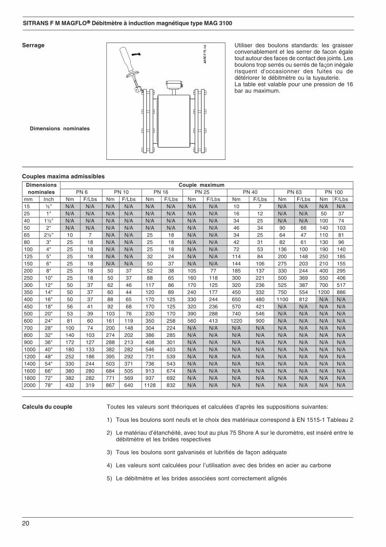
Utiliser des boulons standards: les graisserconvenablement et les serrer de facon égaletout autour des faces de contact des joints. Lesboulons trop serrés ou serrés de faςon inégalerisquent d'occasionner des fuites ou dedétériorer le débitmètre ou la tuyauterie.La table est valable pour une pression de 16bar au maximum.
Serrage
Calculs du couple Toutes les valeurs sont théoriques et calculées d’après les suppositions suivantes:
1) Tous les boulons sont neufs et le choix des matériaux correspond à EN 1515-1 Tableau 2
2) Le matériau d’étanchéité, avec tout au plus 75 Shore A sur le duromètre, est inséré entre ledébitmètre et les brides respectives
3) Tous les boulons sont galvanisés et lubrifiés de façon adéquate
4) Les valeurs sont calculées pour l’utilisation avec des brides en acier au carbone
5) Le débitmètre et les brides associées sont correctement alignés
Couples maxima admissiblesDimensions Couple maximumnominales PN 6 PN 10 PN 16 PN 25 PN 40 PN 63 PN 100
mm Inch Nm F/Lbs Nm F/Lbs Nm F/Lbs Nm F/Lbs Nm F/Lbs Nm F/Lbs Nm F/Lbs15 ½” N/A N/A N/A N/A N/A N/A N/A N/A 10 7 N/A N/A N/A N/A25 1" N/A N/A N/A N/A N/A N/A N/A N/A 16 12 N/A N/A 50 3740 1½” N/A N/A N/A N/A N/A N/A N/A N/A 34 25 N/A N/A 100 7450 2" N/A N/A N/A N/A N/A N/A N/A N/A 46 34 90 66 140 10365 2½” 10 7 N/A N/A 25 18 N/A N/A 34 25 64 47 110 8180 3" 25 18 N/A N/A 25 18 N/A N/A 42 31 82 61 130 96100 4" 25 18 N/A N/A 25 18 N/A N/A 72 53 136 100 190 140125 5" 25 18 N/A N/A 32 24 N/A N/A 114 84 200 148 250 185150 6" 25 18 N/A N/A 50 37 N/A N/A 144 106 275 203 210 155200 8" 25 18 50 37 52 38 105 77 185 137 330 244 400 295250 10" 25 18 50 37 88 65 160 118 300 221 500 369 550 406300 12" 50 37 62 46 117 86 170 125 320 236 525 387 700 517350 14" 50 37 60 44 120 89 240 177 450 332 750 554 1200 886400 16" 50 37 88 65 170 125 330 244 650 480 1100 812 N/A N/A450 18" 56 41 92 68 170 125 320 236 570 421 N/A N/A N/A N/A500 20" 53 39 103 76 230 170 390 288 740 546 N/A N/A N/A N/A600 24" 81 60 161 119 350 258 560 413 1220 900 N/A N/A N/A N/A700 28" 100 74 200 148 304 224 N/A N/A N/A N/A N/A N/A N/A N/A800 32" 140 103 274 202 386 285 N/A N/A N/A N/A N/A N/A N/A N/A900 36" 172 127 288 213 408 301 N/A N/A N/A N/A N/A N/A N/A N/A1000 40" 180 133 382 282 546 403 N/A N/A N/A N/A N/A N/A N/A N/A1200 48" 252 186 395 292 731 539 N/A N/A N/A N/A N/A N/A N/A N/A1400 54" 330 244 503 371 736 543 N/A N/A N/A N/A N/A N/A N/A N/A1600 66" 380 280 684 505 913 674 N/A N/A N/A N/A N/A N/A N/A N/A1800 72" 382 282 771 569 937 692 N/A N/A N/A N/A N/A N/A N/A N/A2000 78" 432 319 867 640 1128 832 N/A N/A N/A N/A N/A N/A N/A N/A
Dimensions nominales
21
SITRANS F M MAGFLO®®®®® Débitmètre à induction magnétique type MAG 3100
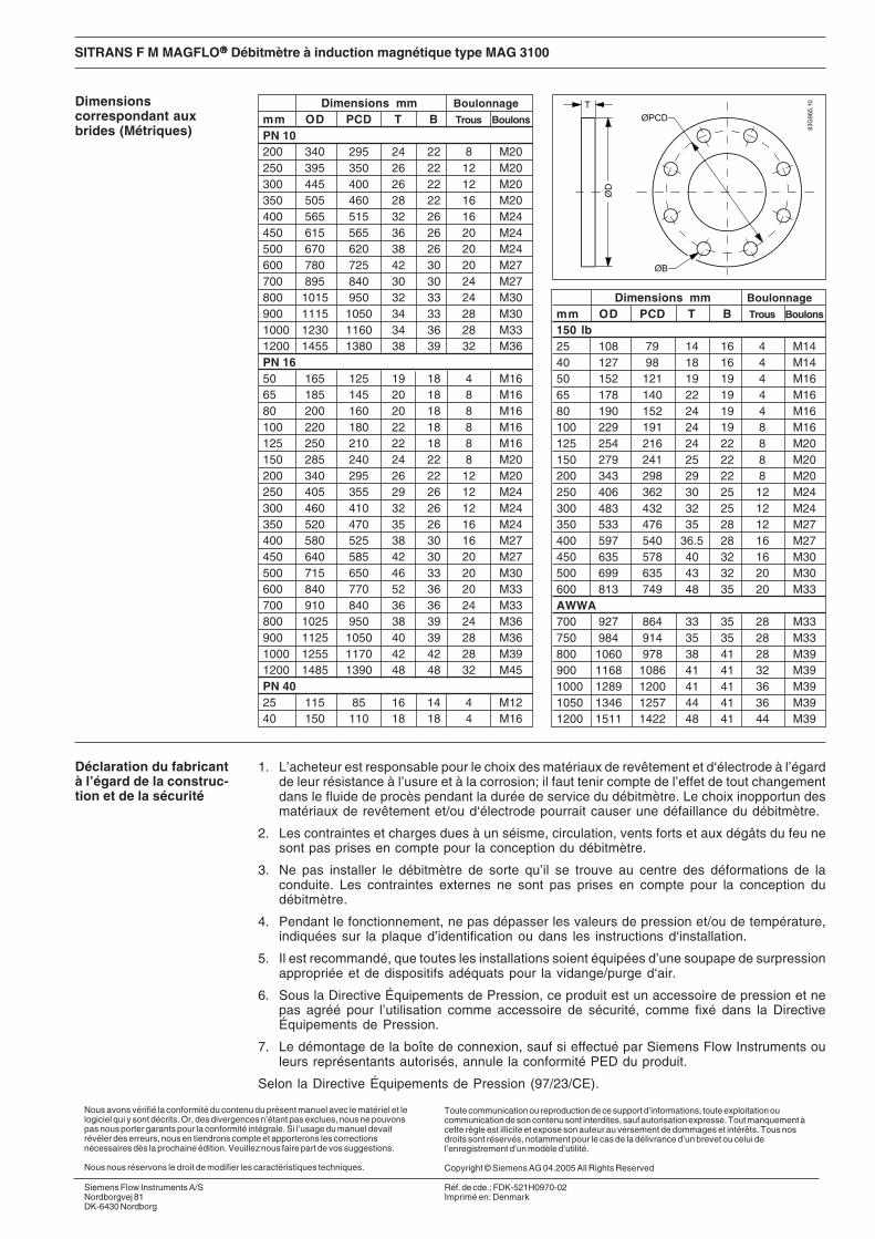
Dimensionscorrespondant auxbrides (Métriques)
Dimensions mm Boulonnagemm OD PCD T B Trous Boulons
PN 10200 340 295 24 22 8 M20250 395 350 26 22 12 M20300 445 400 26 22 12 M20350 505 460 28 22 16 M20400 565 515 32 26 16 M24450 615 565 36 26 20 M24500 670 620 38 26 20 M24600 780 725 42 30 20 M27700 895 840 30 30 24 M27800 1015 950 32 33 24 M30900 1115 1050 34 33 28 M301000 1230 1160 34 36 28 M331200 1455 1380 38 39 32 M36PN 1650 165 125 19 18 4 M1665 185 145 20 18 8 M1680 200 160 20 18 8 M16100 220 180 22 18 8 M16125 250 210 22 18 8 M16150 285 240 24 22 8 M20200 340 295 26 22 12 M20250 405 355 29 26 12 M24300 460 410 32 26 12 M24350 520 470 35 26 16 M24400 580 525 38 30 16 M27450 640 585 42 30 20 M27500 715 650 46 33 20 M30600 840 770 52 36 20 M33700 910 840 36 36 24 M33800 1025 950 38 39 24 M36900 1125 1050 40 39 28 M361000 1255 1170 42 42 28 M391200 1485 1390 48 48 32 M45PN 4025 115 85 16 14 4 M1240 150 110 18 18 4 M16
Dimensions mm Boulonnagemm OD PCD T B Trous Boulons
150 lb25 108 79 14 16 4 M1440 127 98 18 16 4 M1450 152 121 19 19 4 M1665 178 140 22 19 4 M1680 190 152 24 19 4 M16100 229 191 24 19 8 M16125 254 216 24 22 8 M20150 279 241 25 22 8 M20200 343 298 29 22 8 M20250 406 362 30 25 12 M24300 483 432 32 25 12 M24350 533 476 35 28 12 M27400 597 540 36.5 28 16 M27450 635 578 40 32 16 M30500 699 635 43 32 20 M30600 813 749 48 35 20 M33AWWA700 927 864 33 35 28 M33750 984 914 35 35 28 M33800 1060 978 38 41 28 M39900 1168 1086 41 41 32 M391000 1289 1200 41 41 36 M391050 1346 1257 44 41 36 M391200 1511 1422 48 41 44 M39
1. L’acheteur est responsable pour le choix des matériaux de revêtement et d‘électrode à l’égardde leur résistance à l’usure et à la corrosion; il faut tenir compte de l’effet de tout changementdans le fluide de procès pendant la durée de service du débitmètre. Le choix inopportun desmatériaux de revêtement et/ou d‘électrode pourrait causer une défaillance du débitmètre.
2. Les contraintes et charges dues à un séisme, circulation, vents forts et aux dégâts du feu nesont pas prises en compte pour la conception du débitmètre.
3. Ne pas installer le débitmètre de sorte qu’il se trouve au centre des déformations de laconduite. Les contraintes externes ne sont pas prises en compte pour la conception dudébitmètre.
4. Pendant le fonctionnement, ne pas dépasser les valeurs de pression et/ou de température,indiquées sur la plaque d’identification ou dans les instructions d‘installation.
5. Il est recommandé, que toutes les installations soient équipées d’une soupape de surpressionappropriée et de dispositifs adéquats pour la vidange/purge d‘air.
6. Sous la Directive Équipements de Pression, ce produit est un accessoire de pression et nepas agréé pour l’utilisation comme accessoire de sécurité, comme fixé dans la DirectiveÉquipements de Pression.
7. Le démontage de la boîte de connexion, sauf si effectué par Siemens Flow Instruments ouleurs représentants autorisés, annule la conformité PED du produit.
Selon la Directive Équipements de Pression (97/23/CE).
Déclaration du fabricantà l’égard de la construc-tion et de la sécurité
Nous avons vérifié la conformité du contenu du présent manuel avec le matériel et lelogiciel qui y sont décrits. Or, des divergences n’étant pas exclues, nous ne pouvonspas nous porter garants pour la conformité intégrale. Si l’usage du manuel devaitrévéler des erreurs, nous en tiendrons compte et apporterons les correctionsnécessaires dès la prochaine édition. Veuillez nous faire part de vos suggestions.
Nous nous réservons le droit de modifier les caractéristiques techniques.
Toute communication ou reproduction de ce support d’informations, toute exploitation oucommunication de son contenu sont interdites, sauf autorisation expresse. Tout manquement àcette règle est illicite et expose son auteur au versement de dommages et intérêts. Tous nosdroits sont réservés, notamment pour le cas de la délivrance d’un brevet ou celui del’enregistrement d’un modèle d’utilité.
Copyright © Siemens AG 04.2005 All Rights Reserved
Siemens Flow Instruments A/SNordborgvej 81DK-6430 Nordborg
Réf. de cde.: FDK-521H0970-02Imprimé en: Denmark

SITRANS F M MAGFLO®®®®®
Magnetisk induktiv flowmålertype MAG 3100
083R
9159
083R
9159
SFIDK.PI.026.R2.52
Siemens Flow Instruments SITRANS F M MAGFLO® magnetisk induktive flowmålere består af etmålehoved og en transmitter. Denne instruktion omhandler installation af målehovedet. For yderligerevejledning om installation af målehoved og transmitter se SITRANS F M MAGFLO® håndbog.
Indledning
MAG 3100, kompakt/separatMål & vægt
s
Teknisk dokumentationsmateriale (håndbøger, instruktioner, manualer osv.) på heleSITRANS F produktprogrammet er tilgængelig på vores hjemmeside under følgende links:
English: http://www4.ad.siemens.de/WW/view/en/10806951/133300
INSTRUCTIONS DANSK
fortsættelse næste side
A1) A1 B D1 L2) AS AWWA TC 3)
2129 E, C-207AS 4087 Class
PN PN PN PN PN Class Class Class D6, 10, 25 40 64 100 150 300 14-21,
16 35[mm] [inch] [mm] [mm] [mm] [mm] [mm] [mm] [mm] [mm] [mm] [mm] [mm] [mm] [mm] [mm] [kg]
25 1 187 338 59 104 200 200 200 - 260 200 200 200 1,2 540 1½ 197 348 82 124 200 200 200 - 280 200 200 200 1,2 850 2 205 356 72 139 200 200 200 276 300 200 200 200 1,2 965 2½ 212 363 72 154 200 200 200 320 350 200 272 200 1,2 1180 3 222 373 72 174 200 272 272 323 340 272 272 200 1,2 12
100 4 242 393 85 214 250 250 250 380 400 250 310 250 1,2 16125 5 255 406 85 239 250 250 250 420 450 250 335 250 1,2 19150 6 276 427 85 282 300 300 300 415 450 300 300 300 1,2 27200 8 304 455 137 338 350 350 350 480 530 350 350 350 1,2 40250 10 332 483 137 393 450 450 450 550 620 450 450 450 1,2 60300 12 357 508 137 444 500 500 500 600 680 500 500 500 1,6 80350 14 362 513 270 462 550 550 550 700 800 550 550 550 - 1,6 110400 16 387 538 270 512 600 600 600 750 - 600 600 600 - 1,6 125450 18 418 569 310 563 600 600 600 - - 600 640 600 - 1,6 175500 20 443 594 350 614 625 625 680 - - 680 730 625 - 1,6 200600 24 494 645 430 715 750 750 750 - - 820 860 750 - 1,6 300700 28 544 695 500 816 875 - - - - - - 875 875 2,0 350750 30 571 722 556 869 - - - - - - - 937 937 2,0 380
Vægt 4)
EN 1092-1-2001 BS 1560/ANSI 16.5
Nominelstørrelse

23
SITRANS F M MAGFLO®®®®® Magnetisk flowmåler type MAG 3100
Installation, generelt Flowmåleren kan aflæses og betjenes underså at sige alle indbygningsforhold, idet dis-playet kan drejes i forhold til målehovedet.For at sikre optimal flowmåling bør man væreopmærksom på følgende:
Målehovedet skal altid være fuldstændig fyldtmed væske.
Derfor bør man undgå:• Installation på det højeste sted i rørsystemet.• Installation i lodrette rør med frit udløb.
Ved delvist fyldte rør eller rør med nedadgå-ende flowretning og frie udløb bør flowmålerenplaceres i et U-rør.
1) 13 mm kortere med AISI-klemkasse (Ex og høj temperatur)2) Ved brug af jordingsflanger forøges jordingsflangens og pakningens tykkelse med indbygningslængden3) TC = Jordingsring type C4) Anslåede vægtangivelser, der gælder for PN 16 uden transmitter
D = Flangens udvendige diameter, jf. flangetabellerne
800 32 606 757 560 939 1000 - - - - - - 1000 1000 2,0 475900 36 653 804 630 1042 1125 - - - - - - 1125 1125 2,0 5601000 40 704 906 670 1146 1250 - - - - - - 1250 1250 2,0 7001100 44 755 906 770 1248 1375 - - - - - - - - 2,0 12001200 48 810 961 792 1348 1500 - - - - - - 1500 1500 2,0 12501400 56 925 1076 1000 1675 1750 - - - - - - - - 3,0 17531500 50 972 1123 1020 1672 - - - - - - - 1875 1875 3,0 26001600 64 1025 1176 1130 1915 2000 - - - - - - - - 3,0 23411800 72 1123 1274 1250 1974 2250 - - - - - - - - 3,0 32532000 78 1223 1374 1375 2174 2500 - - - - - - - - 3,0 4060
24
SITRANS F M MAGFLO®®®®® Magnetisk flowmåler type MAG 3100
Montage i vandrette rørMålehovedet monteres som vist på den øver-ste figur. Målehovedet må ikke monteres somvist på den nederste figur af hensyn tilelektrodernes placering øverst, hvor der ermulighed for luftbobler, og nederst, hvor derer mulighed for mudder, slam, sand osv.Med henblik på detektering af tomt målerørvippes målehovedet 45° som vist på denøverste figur.
Måling på slibende væsker og væsker medpartiklerHer anbefales indbygning i lodrette/skrå rør,for at mindske slitage og aflejringer i måle-hovedet.
Ind- og udløbsforholdFor at opnå en nøjagtig flowmåling er detnødvendigt at have lige indløbs- og udløbs-strækninger og en vis afstand til pumper ogventiler.Det er ligeledes vigtigt, at flowmåleren er cen-treret i forhold til rørsystemets flanger og pak-ninger.
Installation, generelt(fortsættelse)
Montage i store rørFlowmåleren kan også monteres imellem toreduktionsstykker (f. eks. DIN 28545). Ved 8°gælder nedenstående tryktagskurve.Kurverne er gældende for vand.
Eksempel:En flowhastighed på 3 m/s (V) i et målehovedmed en diameterreduktion fra DN 100 til DN80 (d1/d2 = 0,8) forårsager et trykfald på 2,9mbar.
Montage i lodrette rørAnbefalet flowretning: opad. Dette minimererindflydelse på målingen fra evt. gas-/luftbob-ler i væsken.

25
SITRANS F M MAGFLO®®®®® Magnetisk flowmåler type MAG 3100
Potentialeudligning Potentialeudligning udføres med indbyggedejordingselektroder.
Her anvendes et jordingskabel i den ene side.
Her anvendes en jordingsflange, som placeresmellem flowmåleren og den tilstødende rør-flange.
Ved rørsystemer med katodisk beskyttelse skalder tages særlige hensyn.Ved kompakt montering:Transmitteren skal strømforsynes via enskilletransformator. "PE"-klemmen må ikke væretilsluttet.Ved separat montering:Afskærmnigen må kun tilsluttes transmitterensende via en 1,5 µF kondensator.Afskærmningen må aldrig tilsluttes i beggeender.Ved isoleret målehoved:Hvis de ovenstående tilslutningsmuligheder ikkekan accepteres, skal målehovedet isoleres frarørsystemet.
Liner- Passendemateriale jordingsflange
Alle bortset fra Type CPTFEPTFE Type E
Elektrisk ledende rørsystem
Ikke-ledende rørsystem
Katodisk beskyttetrørsystem
Med jordingselektroder
Uden jordingselektroder

26
SITRANS F M MAGFLO®®®®® Magnetisk flowmåler type MAG 3100
Målehovedet monteres mellem to flanger. Derbruges kun pakninger, hvis måleren er monteretmed jordingsflanger, idet lineren bruges sompakning.
Montering
Indløbsbeskyttelse Ved slidende væsker kan det være nødvendigtat montere en indløbsbeskyttelse på flow-måleren. Hertil bruges jordingsflangerne typeC.
Sammenhæng mellemflange materiale,temperatur og arbejdstryk Flanger i henhold til EN 1092-1
Material Flange Temperatur °°°°°Cmateriale tryk −20 50 1001C1 (A105) PN 6 6,0 5,8 5,6
PN10 10,0 9,7 9,4PN16 16,0 15,5 15,0PN 25 25,0 24,2 23,4PN 40 40,0 38,7 37,5PN 63 63,0 63,0 63,0PN 100 100,0 100,0 100,0
2C1 (304) PN 6 5,5 5,3 4,5PN 10 9,1 8,8 7,5PN 16 14,7 14,2 12,1PN 25 23,0 22,1 18,9PN 40 36,8 35,4 30,3PN 63 57,9 55,8 47,7PN 100 91,9 88,6 75,7
2C2 (316) PN 6 5,5 5,3 4,6PN 10 9,1 8,9 7,8PN 16 14,7 14,3 12,5PN 25 23,0 22,3 19,5PN 40 36,8 35,6 31,3PN 63 57,9 56,1 49,2PN 100 91,9 89,1 78,1
Metrisk (tryk angivet i bar)
Ovenstående tabel viser hvilken indflydelse en temperatur stigning eller valg af flange materiale,har på den aktuelle flanges maksimale arbejdstryk. De enkelte værdier er uafhængige af denaktuelle dimension for flangen.For mellemliggende temperaturer anvendes den nærmeste højere temperatur angivelse.
EksempelFor en PN16 flange fremstillet af materiale 2C2 (316) der anvendes ved 80 °C, vil maksimalarbejdstryk være 12,5 bar.
Flanger i henhold til EN 1092-1Material Flange Temperatur °°°°°Fmateriale tryk −5 122 212ASTM A105 PN 6 87 84 81
PN 10 145 141 136PN 16 232 225 218PN 25 363 351 339PN 40 580 561 544PN 63 914 914 914PN 100 1450 1450 1450
ASTM A240 PN 6 80 77 65304 PN 10 132 128 109
PN 16 213 206 175PN 25 334 320 274PN 40 534 513 439PN 63 840 809 692PN 100 1333 1285 1098
ASTM A240 PN 6 80 77 67316 PN 10 132 129 113
PN 16 213 207 181PN 25 334 323 283PN 40 534 516 454PN 63 840 813 713PN 100 1333 1292 1132
Imperial (tryk angivet i Psi)
27
SITRANS F M MAGFLO®®®®® Magnetisk flowmåler type MAG 3100
Standardbolte skal være velsmurte og spæn-des jævnt rundt omkring pakfladen. For storeller "skæv" tilspænding kan forårsage utæt-heder/skader på flowmåler og rørsystem.Nedenstående tabel er gyldig for tryk indtil max.16 bar.
Tilspænding
Moment beregning Alle værdier er teoretiske og beregnet ud fra følgende forudsætninger:
1) Alle bolte er nye og boltematerialet er valgt i henhold til EN 1515-1 tabel 2
2) Pakningsmaterialet, som anvendes mellem flowmåler og modflange må ikke overstigehårdhed 75 shore A
3) Alle bolte er galvaniserede og velsmurte
4) De beregnede værdier er gældende for flanger af kulstofstål (St. 37.2)
5) Flowmåleren og modflangen flugter korrekt på linie
Maksimal tilladelig tilspændingsmomentNominel Maksimal momentstørrelse PN 6 PN 10 PN 16 PN 25 PN 40 PN 63 PN 100
mm Inch Nm F/Lbs Nm F/Lbs Nm F/Lbs Nm F/Lbs Nm F/Lbs Nm F/Lbs Nm F/Lbs15 ½” N/A N/A N/A N/A N/A N/A N/A N/A 10 7 N/A N/A N/A N/A25 1" N/A N/A N/A N/A N/A N/A N/A N/A 16 12 N/A N/A 50 3740 1½” N/A N/A N/A N/A N/A N/A N/A N/A 34 25 N/A N/A 100 7450 2" N/A N/A N/A N/A N/A N/A N/A N/A 46 34 90 66 140 10365 2½” 10 7 N/A N/A 25 18 N/A N/A 34 25 64 47 110 8180 3" 25 18 N/A N/A 25 18 N/A N/A 42 31 82 61 130 96100 4" 25 18 N/A N/A 25 18 N/A N/A 72 53 136 100 190 140125 5" 25 18 N/A N/A 32 24 N/A N/A 114 84 200 148 250 185150 6" 25 18 N/A N/A 50 37 N/A N/A 144 106 275 203 210 155200 8" 25 18 50 37 52 38 105 77 185 137 330 244 400 295250 10" 25 18 50 37 88 65 160 118 300 221 500 369 550 406300 12" 50 37 62 46 117 86 170 125 320 236 525 387 700 517350 14" 50 37 60 44 120 89 240 177 450 332 750 554 1200 886400 16" 50 37 88 65 170 125 330 244 650 480 1100 812 N/A N/A450 18" 56 41 92 68 170 125 320 236 570 421 N/A N/A N/A N/A500 20" 53 39 103 76 230 170 390 288 740 546 N/A N/A N/A N/A600 24" 81 60 161 119 350 258 560 413 1220 900 N/A N/A N/A N/A700 28" 100 74 200 148 304 224 N/A N/A N/A N/A N/A N/A N/A N/A800 32" 140 103 274 202 386 285 N/A N/A N/A N/A N/A N/A N/A N/A900 36" 172 127 288 213 408 301 N/A N/A N/A N/A N/A N/A N/A N/A1000 40" 180 133 382 282 546 403 N/A N/A N/A N/A N/A N/A N/A N/A1200 48" 252 186 395 292 731 539 N/A N/A N/A N/A N/A N/A N/A N/A1400 54" 330 244 503 371 736 543 N/A N/A N/A N/A N/A N/A N/A N/A1600 66" 380 280 684 505 913 674 N/A N/A N/A N/A N/A N/A N/A N/A1800 72" 382 282 771 569 937 692 N/A N/A N/A N/A N/A N/A N/A N/A2000 78" 432 319 867 640 1128 832 N/A N/A N/A N/A N/A N/A N/A N/A

28
SITRANS F M MAGFLO®®®®® Magnetisk flowmåler type MAG 3100
Flange dimensioner(metrisk)
Mål mm Boltemm OD PCD T B Hul Dia.PN 10200 340 295 24 22 8 M20250 395 350 26 22 12 M20300 445 400 26 22 12 M20350 505 460 28 22 16 M20400 565 515 32 26 16 M24450 615 565 36 26 20 M24500 670 620 38 26 20 M24600 780 725 42 30 20 M27700 895 840 30 30 24 M27800 1015 950 32 33 24 M30900 1115 1050 34 33 28 M301000 1230 1160 34 36 28 M331200 1455 1380 38 39 32 M36PN 1650 165 125 19 18 4 M1665 185 145 20 18 8 M1680 200 160 20 18 8 M16100 220 180 22 18 8 M16125 250 210 22 18 8 M16150 285 240 24 22 8 M20200 340 295 26 22 12 M20250 405 355 29 26 12 M24300 460 410 32 26 12 M24350 520 470 35 26 16 M24400 580 525 38 30 16 M27450 640 585 42 30 20 M27500 715 650 46 33 20 M30600 840 770 52 36 20 M33700 910 840 36 36 24 M33800 1025 950 38 39 24 M36900 1125 1050 40 39 28 M361000 1255 1170 42 42 28 M391200 1485 1390 48 48 32 M45PN 4025 115 85 16 14 4 M1240 150 110 18 18 4 M16
Mål mm Boltemm OD PCD T B Hul Dia.150 lb25 108 79 14 16 4 M1440 127 98 18 16 4 M1450 152 121 19 19 4 M1665 178 140 22 19 4 M1680 190 152 24 19 4 M16100 229 191 24 19 8 M16125 254 216 24 22 8 M20150 279 241 25 22 8 M20200 343 298 29 22 8 M20250 406 362 30 25 12 M24300 483 432 32 25 12 M24350 533 476 35 28 12 M27400 597 540 36,5 28 16 M27450 635 578 40 32 16 M30500 699 635 43 32 20 M30600 813 749 48 35 20 M33AWWA700 927 864 33 35 28 M33750 984 914 35 35 28 M33800 1060 978 38 41 28 M39900 1168 1086 41 41 32 M391000 1289 1200 41 41 36 M391050 1346 1257 44 41 36 M391200 1511 1422 48 41 44 M39
1. Ansvaret for den valgte lining og elektrode materiales holdbarhed overfor slitage og korrossionpåhviler køber; indflydelse fra evt. ændring i mediesammensætning på et vilkårligt tidspunkti produktets levetid skal herunder tages i betragtning. Forkert valg af lining og/eller elektrodemateriale kan medføre udfald af flowmåleren.
2. Påvirkninger kommende fra jordskælv, trafik, kraftige vindforhold og ildløs er ikke taget ibetragtning ved udformning af flowmåleren.
3. Flowmåleren må ikke installeres, således at den mekanisk belaster omkringliggende rørføring.Udvendig belastning er ikke medregnet ved udformning af flowmåleren.
4. Ved anvendelse skal de, på skilte eller i instruktionen, angivne tryk og/eller temperaturgrænser overholdes og må ikke overskrides.
5. Det anbefales at alle installationer inkluderer en sikkerhedsventil for mulig udluftning/dræning.
6. I henhold til trykdirektivet PED er denne flowmåler et tryktilbehør og som sådant ikke godkendtsom sikkerheds tilbehør i henhold til PED.
7. Afmontering af klemkasse fra flowmåler, medfører bortfald af PED overensstemmelse forproduktet; medmindre afmontering udføres af Siemens Flow Instruments eller en af demgodkendt person.
I overensstemmelse med trykdirektivet Pressure Equipment Directive (97/23/EC)
Producentens udsagnomkring udseende ogsikkerhed
We have checked the contents of this manual for agreement with the hardware andsoftware described. Since deviations cannot be precluded entirely, we cannot guaranteefull agreement. However, the data in this manual are reviewed regularly and anynecessary corrections included in subsequent editions. Suggestions for improvementare always welcomed.
Technical data subject to change without prior notice.
The reproduction, transmission or use of this document or its contents is not permitted withoutexpress written authority.Offenders will be liable for damages. All rights, including rights created by patent grant orregistration of a utility model or design, are reserved.
Copyright © Siemens AG 04.2005 All Rights Reserved
Siemens Flow Instruments A/SNordborgvej 81DK-6430 Nordborg
Order no.: FDK-521H0970-02Printed in: Denmark