sip trunking configuration guide for samsung 7100 v4.53c - cox
TRANSCRIPT

www.CoxBusiness.com
SIP Trunking Configuration Guide
for Samsung 7100
V4.53c OfficeServ DM V1.02c 2011.03.18
© 2011, Cox Communications, Inc. All rights reserved. This documentation is the confidential and proprietary intellectual property of Cox Communications, Inc. Any unauthorized use, reproduction, preparation of derivative works, performance, or display of this document, or software represented by this document is strictly prohibited.

Table of Contents 1 Audience ................................................................................................................................................4 2 Introduction ............................................................................................................................................4
2.1 tekVizion Labs ................................................................................................................................5 3 SIP Trunking Network Components ......................................................................................................6
3.1 Hardware Components...................................................................................................................7 3.2 Software Requirements ..................................................................................................................7
4 Features.................................................................................................................................................8 4.1 SIP Registration Method.................................................................................................................8 4.2 Features Supported........................................................................................................................8 4.3 Features Not Supported .................................................................................................................8
5 Caveats and Limitations.........................................................................................................................9 6 Configuration........................................................................................................................................10
6.1 Configuration Checklist.................................................................................................................10 6.2 IP Address Worksheet..................................................................................................................11 6.3 Samsung 7100 Detailed Configuration Steps ..............................................................................11
6.3.1 Set System IP Address .........................................................................................................12 6.3.2 Assign Licenses Keys ...........................................................................................................15 6.3.3 Set System Options...............................................................................................................16 6.3.4 Sip Carrier Options................................................................................................................18 6.3.5 Trunk Groups.........................................................................................................................21 6.3.6 Assign Station Name.............................................................................................................23 6.3.7 Pickup Group Station Assignment/Call ID block ...................................................................24 6.3.8 Assign Fax\Modem Station ...................................................................................................25 6.3.9 Station Groups.......................................................................................................................26 6.3.10 Account Codes ......................................................................................................................28 6.3.11 Authorization Codes ..............................................................................................................29 6.3.12 Allow External Forward .........................................................................................................30 6.3.13 Auto Attendant.......................................................................................................................31
6.4 Samsung 7100 Dial Plan Configuration .......................................................................................34 6.4.1 Incoming Routing ..................................................................................................................34 6.4.2 Outgoing Dial Plan ................................................................................................................35 6.4.3 Send CLI Number..................................................................................................................37 6.4.4 Calling Line ID Spoofing........................................................................................................38
Table of Figures Figure 1 - Cox Fiber Network........................................................................................................................4 Figure 2 - SIP Trunk Lab Reference Network...............................................................................................6 Figure 3 Set IP Address in PC ....................................................................................................................12 Figure 4 Link Setup .....................................................................................................................................13 Figure 5 Login Prompt.................................................................................................................................13 Figure 6 System Selection (2.1.0)...............................................................................................................14 Figure 7 System Restart .............................................................................................................................14 Figure 8 License Key (2.1.4) .......................................................................................................................15 Figure 9 System Options (2.1.5) .................................................................................................................17 Figure 10 Sip Carrier Options (5.2.3)..........................................................................................................19 Figure 11 Sip Carrier Options cont... (5.2.13) .............................................................................................20 Figure 12 TRK-GRP (2.8.0) ........................................................................................................................21
Property of Cox Communications, Inc. Version 1.0 Page 2 of 38

Figure 13 Trunk Numbers (2.8.0)................................................................................................................22 Figure 14 Trunk Groups (4.1.2) ..................................................................................................................23 Figure 15 Port Common Data (2.4.2)..........................................................................................................24 Figure 16 Station Data (2.5.1).....................................................................................................................24 Figure 17 Analog/Digitial Interface..............................................................................................................25 Figure 18 Numbering Plan MW SLI (2.8.0).................................................................................................25 Figure 19 SLI Data (2.5.7)...........................................................................................................................26 Figure 20 Station Groups (4.1.1) ................................................................................................................27 Figure 21 Forced Code (4.5.1)....................................................................................................................28 Figure 22 Account Code (4.5.2)..................................................................................................................28 Figure 23 Station Key (4.9.2) ......................................................................................................................29 Figure 24 Forced Code Authorize (4.5.1) ...................................................................................................29 Figure 25 Authorization Code (4.5.3)..........................................................................................................30 Figure 26 Numbering Plan Features...........................................................................................................30 Figure 27 UCD Forward Wakeup Options (5.14.6).....................................................................................31 Figure 28 New Block (8.1.4)........................................................................................................................32 Figure 29 Dial Block(DialOffPrim) ...............................................................................................................32 Figure 30 Menu Block (Day Main) ..............................................................................................................33 Figure 31 DID Ringing (3.2.3) .....................................................................................................................34 Figure 32 Port Class (4.7.1) ........................................................................................................................35 Figure 33 COS Contents (4.7.2) .................................................................................................................35 Figure 34 Toll Deny Table (4.8.1) ...............................................................................................................36 Figure 35 Toll Allow Table (4.8.2) ...............................................................................................................36 Figure 36 Send CLI Number (2.4.3)............................................................................................................37
Table of Tables Table 1 – PBX Configuration Steps ............................................................................................................10 Table 2 – IP Addresses...............................................................................................................................11
Property of Cox Communications, Inc. Version 1.0 Page 3 of 38

1 Audience This document is intended for the SIP trunk customer’s technical staff and Value Added Retailer (VAR) having installation and operational responsibilities.
2 Introduction
This Configuration Guide describes configuration steps for Cox SIP trunking with the Samsung OfficeServ 7100 PBX. Cox SIP trunking is a scalable and efficient IP trunking telecommunication solution for your business that provides all the traditional services such as Direct Inward Dialing, Hunting, Calling Name, Calling Number, Local/Long Distance and Business Continuity options, including:
Burstable Trunk Capacity – Dynamically increases call capacity during peak busy periods so your customers never receive a busy signal.
Call Forward Always – On the trunk group pilot number for all calls in case of an outage (i.e., flood, fire, loss of power, etc.).
Call Forward Not Reachable – On the trunk group pilot number that operates on a per-call contingency basis to forward the call to any PSTN number (i.e., call center or alternate office location) during temporary call completion impairments.
Route Exhaustion – Automatic reroute of trunk group calls to any PSTN phone number (i.e., a call center) if calls can’t be completed to the PBX.
Support for geo-redundant PBX deployments and automatic reroute of SIP trunks to the backup customer data center.
All calls are routed over Cox’s national fiber network with guaranteed Quality of Service (QoS); calls never traverse the Internet.
Figure 1 - Cox Fiber Network
Property of Cox Communications, Inc. Version 1.0 Page 4 of 38

2.1 tekVizion Labs tekVizion LabsTM is an independent testing and Verification facility offered by tekVizion PVS, Inc. (“tekVizion”). tekVizion Labs offers several types of testing services including:
Remote Testing – provides secure, remote access to certain products in tekVizion Labs for pre-Verification and ad hoc testing
Verification Testing – Verification of interoperability performed on-site at tekVizion Labs between two products or in a multi-vendor configuration (“solution Verification”)
Product Assessment – independent assessment and verification of product functionality, interface usability, assessment of differentiating features as well as suggestions for added functionality, stress and performance testing, etc.
tekVizion is a systems integrator specifically dedicated to the telecommunications industry. Our core services include consulting/solution design, interoperability/Verification testing, integration, custom software development and solution support services. Our services helps service providers achieve a smooth transition to packet-voice networks, speeding delivery of integrated services. While we have expertise covering a wide range of technologies, we have extensive experience surrounding our FastForward>> practice areas which include: SIP Trunking, Packet Voice, Service Delivery, and Integrated Services. The tekVizion team brings together experience from the leading service providers and vendors in telecom. Our unique expertise includes legacy switching services and platforms, and unparalleled product knowledge, interoperability and integration experience on a vast array of VoIP and other next-generation products. We rely on this combined experience to do what we do best: help our clients advance the rollout of services that excite customers and result in new revenues for the bottom line. tekVizion leverages this real-world, multi-vendor integration and test experience and proven processes to offer services to vendors, network operators, enhanced service providers, large enterprises and other professional services firms. tekVizion’s headquarters, along with a state-of-the-art test lab and Executive Briefing Center, is located in the Telecom Corridor® in Richardson, Texas. (For more information on tekVizion and its practice areas, please visit tekVizion Labs’s web site at www.tekVizionlabs.com.)
Property of Cox Communications, Inc. Version 1.0 Page 5 of 38

3 SIP Trunking Network Components
The network for the SIP trunk reference configuration is illustrated below and is representative of a Samsung 7100 configuration.
Figure 2 - SIP Trunk Lab Reference Network Note: The Samsung 7100 does not offer DHCP server for dynamic IP address assignment for the SIP phones; however, the Cox Enterprise Session Border Controller (E-SBC) requires a static LAN IP address that must be manually assigned by the LAN network administrator. The DHCP server is provisioned on the Ethernet switch. The DHCP’s IP address pool is constrained so that the E-SBC can be assigned an IP address outside of the pool. The lab network consists of the following components:
Samsung 7100 PBX for voice features, SIP proxy and SIP trunk termination. Various SIP phones on the local LAN. The Cox E-SBC is the Edgewater Networks (www.edgewaternetworks.com) EdgeMarc appliance.
The EdgeMarc is the service demarcation point between customer’s LAN network and Cox’s WAN network and provides firewall/NAT traversal, B2BUA and SIP Application-level gateway. The EdgeMarc has diverse routes to a primary and secondary Acme SBC.
Acme Packet Net-Net 9200 Session Border Controllers (SBC).
Property of Cox Communications, Inc. Version 1.0 Page 6 of 38

3.1 Hardware Components Samsung 7100
Samsung SMT-i5210 Phone
Samsung DS5021-D Phone
Analog fax machine
EdgeMarc 4550 E-SBC
3.2 Software Requirements Samsung 7100 Release V4.53c
Samsung OfficeServ Device Manager V1.02c 2011.03.18
EdgeMarc 4550 9.12.5 Release
Property of Cox Communications, Inc. Version 1.0 Page 7 of 38

4 Features
4.1 SIP Registration Method Cox Network requires SIP REGISTER support to allow the IP-PBX to originate calls from the IP-PBX and to send calls to the PBX from the PSTN. Samsung 7100 supports SIP Register with authentication. Cox implementation team provides the Pilot number and the authentication key, which should be provisioned in the Samsung 7100. How to configure these in the Samsung 7100 are shown in Section 6.3.4.
4.2 Features Supported Basic calls using G.711ulaw
Calling Party Number Presentation
Anonymous call
Call Transfer
Call Forwarding
Call Hold and Resume
Call Pickup
Call Waiting
DND
Call Park
Hunt groups (Simultaneous and Sequential Ring)
Three-Way Calling
PBX Auto Attendant to Off-net Numbers
PBX Account Codes
PBX Authorization Codes
Fax Receive T38 Fax
Dial-Up Modem
E911 Call
RFC2833 transcoding
PBX-Defined Caller ID (spoofing)11
4.3 Features Not Supported
Property of Cox Communications, Inc. Version 1.0 Page 8 of 38

5 Caveats and Limitations Samsung 7100 fails to send an outbound fax via G711 or T38. The problem is Samsung 7100
receives an INVITE from the network with G729 and G711ulaw as the codec options and Samsung 7100 sends a 200OK SDP with G729 only. This causes the call to tear down. This a current software limitation. This issue is currently being worked with Samsung. Once a ticket is opened this document will be updated. Note*** Samsung 7100 follows the network CODEC priority of the of the INVITES sdp. A workaround for this issue is if the network can send G711 as first choice in the sdp’s codec list.
When Samsung 7100 places a call on hold for any reason, Samsung 7100 changes the media stream to port 30000. To allow MoH to be heard by the PSTN caller, Cox’s standard configuration for the E-SBC must be modified so that “Do strict RTP source check:” is unchecked. This configuration must be set by Cox technician.
When assigning an analog station (FXS) to be a fax, the value in SLI Data (2.5.7) Figure 19 does not modify the analog ports behavior in version V4.53c
Property of Cox Communications, Inc. Version 1.0 Page 9 of 38

6 Configuration
6.1 Configuration Checklist In this section we present an overview of the steps that are required to configure Samsung 7100 for SIP Trunking as well as all features that were tested. A customer with an in-service PBX need only configure the SIP Carrier Options in 6.3.4 for Cox Business to setup the SIP Trunks. Table 1 – PBX Configuration Steps
Step Description Reference
Step 1 Set System IP Address Section 6.3.1
Step 2 Assign Licenses Keys Section 6.3.2
Step 3 Set System Options Section 6.3.3
Step 4 Sip Carrier Options for Cox Business Section 6.3.4
Step 5 Trunk Groups Section 6.3.5
Step 6 Assign Station Name Section 6.3.6
Step 7 Pickup Group Station Assignment/Call ID Block Section 6.3.7
Step 8 Assign Fax\Modem Station Section 6.3.8
Step 9 Station Groups Section 6.3.9
Step 10 Account Codes Section 6.3.10
Step 11 Authorization Codes Section 6.3.11
Step 12 Allow External Forward Section 6.3.12
Step 13 Auto Attendant Section 6.3.13
Step 14 Incoming Routing Section 6.4.1
Step 15 Outgoing Dial Plan Section 6.4.2
Step 16 Send CLI Number Section 6.4.3
Property of Cox Communications, Inc. Version 1.0 Page 10 of 38
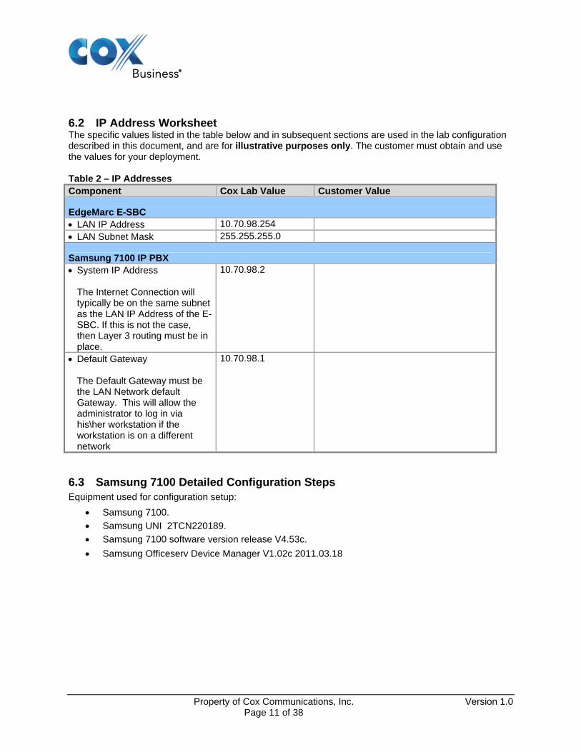
6.2 IP Address Worksheet The specific values listed in the table below and in subsequent sections are used in the lab configuration described in this document, and are for illustrative purposes only. The customer must obtain and use the values for your deployment. Table 2 – IP Addresses Component Cox Lab Value Customer Value
EdgeMarc E-SBC LAN IP Address 10.70.98.254 LAN Subnet Mask 255.255.255.0
Samsung 7100 IP PBX System IP Address
The Internet Connection will typically be on the same subnet as the LAN IP Address of the E-SBC. If this is not the case, then Layer 3 routing must be in place.
10.70.98.2
Default Gateway
The Default Gateway must be the LAN Network default Gateway. This will allow the administrator to log in via his\her workstation if the workstation is on a different network
10.70.98.1
6.3 Samsung 7100 Detailed Configuration Steps Equipment used for configuration setup:
Samsung 7100.
Samsung UNI 2TCN220189.
Samsung 7100 software version release V4.53c.
Samsung Officeserv Device Manager V1.02c 2011.03.18
Property of Cox Communications, Inc. Version 1.0 Page 11 of 38

6.3.1 Set System IP Address This is accomplished via an Ethernet cross-over cable connected from a laptop or PC Ethernet port to the LAN port of the MP10a module. The default IP address of the Samsung 7100, for purposes of this explanation will be 10.100.0.1 with a subnet mask of 255.255.255.0. Document the settings before changing them. Once the steps in 6.3.1 are completed the PC settings will be placed back to their original values. The default IP address for the Samsung 7100 is 10.0.0.10. For the example 10.100.0.1 is used for the Samsung 7100.
1. Set the IP Address on the PC to 10.100.0.2 255.255.255.0
2. Set the Subnet mask to 255.255.255.0.
3. Click on OK
Figure 3 Set IP Address in PC
Property of Cox Communications, Inc. Version 1.0 Page 12 of 38
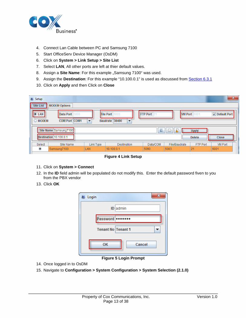
4. Connect Lan Cable between PC and Samsung 7100
5. Start OfficeServ Device Manager (OsDM)
6. Click on System > Link Setup > Site List
7. Select LAN, All other ports are left at thier default values.
8. Assign a Site Name: For this example „Samsung 7100“ was used.
9. Assign the Destination: For this example “10.100.0.1” is used as discussed from Section 6.3.1
10. Click on Apply and then Click on Close
Figure 4 Link Setup
11. Click on System > Connect
12. In the ID field admin will be populated do not modify this. Enter the default password fiven to you from the PBX vendor
13. Click OK
Figure 5 Login Prompt
14. Once logged in to OsDM
15. Navigate to Configuration > System Configuration > System Selection (2.1.0)
Property of Cox Communications, Inc. Version 1.0 Page 13 of 38
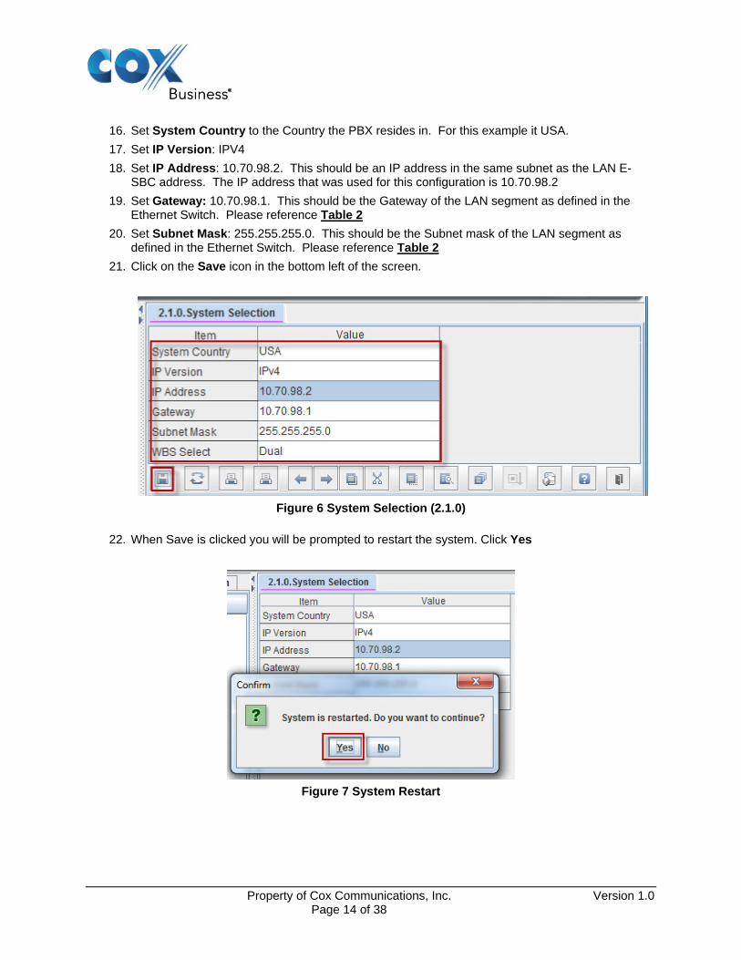
16. Set System Country to the Country the PBX resides in. For this example it USA.
17. Set IP Version: IPV4
18. Set IP Address: 10.70.98.2. This should be an IP address in the same subnet as the LAN E-SBC address. The IP address that was used for this configuration is 10.70.98.2
19. Set Gateway: 10.70.98.1. This should be the Gateway of the LAN segment as defined in the Ethernet Switch. Please reference Table 2
20. Set Subnet Mask: 255.255.255.0. This should be the Subnet mask of the LAN segment as defined in the Ethernet Switch. Please reference Table 2
21. Click on the Save icon in the bottom left of the screen.
Figure 6 System Selection (2.1.0)
22. When Save is clicked you will be prompted to restart the system. Click Yes
Figure 7 System Restart
Property of Cox Communications, Inc. Version 1.0 Page 14 of 38
23. Disconnect the Ethernet Cable between your PC and the Samsung 7100
24. Return the PC to it original configuration with the information stored from step 1 of Section 6.3.1
25. Connect the PC to its original network cable
26. Connect the Samsung 7100 Ethernet cable to the 10.70.98.0 /24 network
27. Modify the Destination address in Figure 4 from 10.100.0.1 to 10.70.98.2 by following steps 5 thru 10 of Section 6.3.1
28. Connect to OsDM by following steps 11 thru 13 of Section 6.3.1
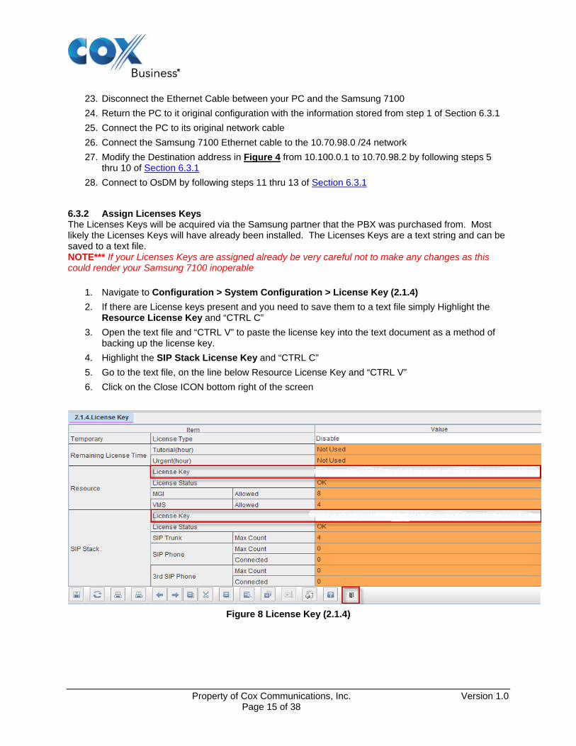
6.3.2 Assign Licenses Keys The Licenses Keys will be acquired via the Samsung partner that the PBX was purchased from. Most likely the Licenses Keys will have already been installed. The Licenses Keys are a text string and can be saved to a text file. NOTE*** If your Licenses Keys are assigned already be very careful not to make any changes as this could render your Samsung 7100 inoperable
1. Navigate to Configuration > System Configuration > License Key (2.1.4)
2. If there are License keys present and you need to save them to a text file simply Highlight the Resource License Key and “CTRL C”
3. Open the text file and “CTRL V” to paste the license key into the text document as a method of backing up the license key.
4. Highlight the SIP Stack License Key and “CTRL C”
5. Go to the text file, on the line below Resource License Key and “CTRL V”
6. Click on the Close ICON bottom right of the screen
Figure 8 License Key (2.1.4)
Property of Cox Communications, Inc. Version 1.0 Page 15 of 38

6.3.3 Set System Options The System Options Shown in Figure 9 are all default values with the exception of “External BGM/MOH”. The IP-PBX was tested with Int.Chime for its MOH source.
1. Set External BGM/MOH: Int.Chime.
2. Set Technician Password: XXXX In the example 5150 was used. This password can only be 4 numbers and is used when programing via any phone
3. Confirm that DTMF Type: Inband(RFC2833)
4. Confirm that SIPT Ringback Message: 183
5. Click on Save
Property of Cox Communications, Inc. Version 1.0 Page 16 of 38
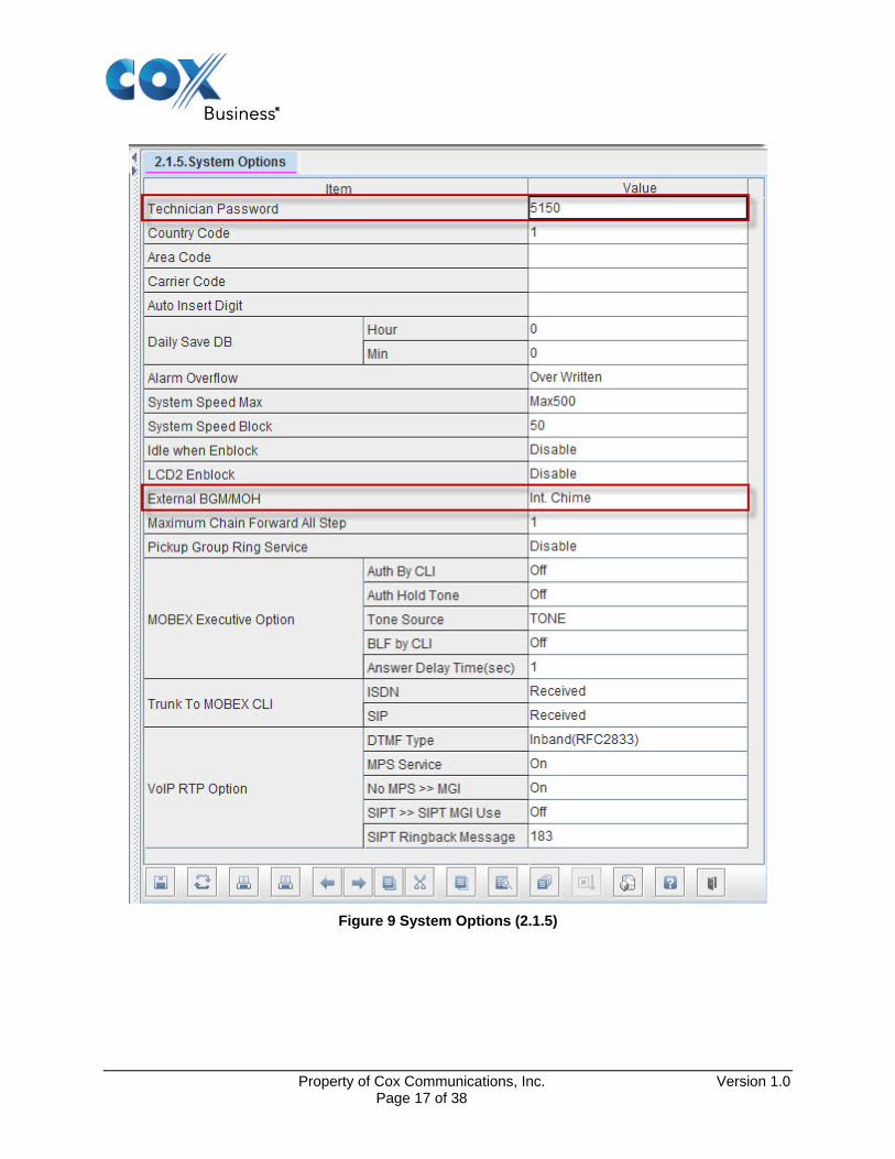
Figure 9 System Options (2.1.5)
Property of Cox Communications, Inc. Version 1.0 Page 17 of 38
6.3.4 Sip Carrier Options Note: Please notice that the Outbound Proxy Server and SIP Domain Name is NOT data field. Please leave these blank. Remember that the E-SBC LAN IP address may/will be different from this example. Please see Figure 2 and Table 2 for the IP address scheme.
1. Navigate to Features > VoIP Options > SIP Carrier Options (5.2.13)
2. Set SIP Carrier Name: Cox This value can be any name that the Enterprise customer wants to use. For this example Cox was used
3. Set SIP Server Enable: Enable
4. Set SIP Service Available: Yes
5. Set Registra Address: This is the static LAN IP address of the Cox E-SBX. Please use the actual E-SBC LAN IP for your network. The IP Address used in this configuration is 10.70.98.254
6. Set Registra Port: 5060
7. Set OutBound Proxy:This is also the static LAN IP address of the Cox E-SBX. Please use the actual E-SBC LAN IP for your network. The IP Address used in this configuration is 10.70.98.254
8. Set Outbound Proxy Port: 5060
9. Set User Name:6782383650
10. Set Auth Username: 6782383650
11. Set Password: ***********
The actual SIP Registration Password and Username will be provided by your Cox Account Representative and must be kept confidential! The Trunk Group Pilot Number (username) is used here for illustration purposes only!
12. Set Supplementary Type: Server Managed Setting this parameter to Server Managed enables Refer support. By enabling refer support Samsung 7100 will not use additional resources when transfering/forwarding calls to the PSTN.
13. Click Save
Property of Cox Communications, Inc. Version 1.0 Page 18 of 38
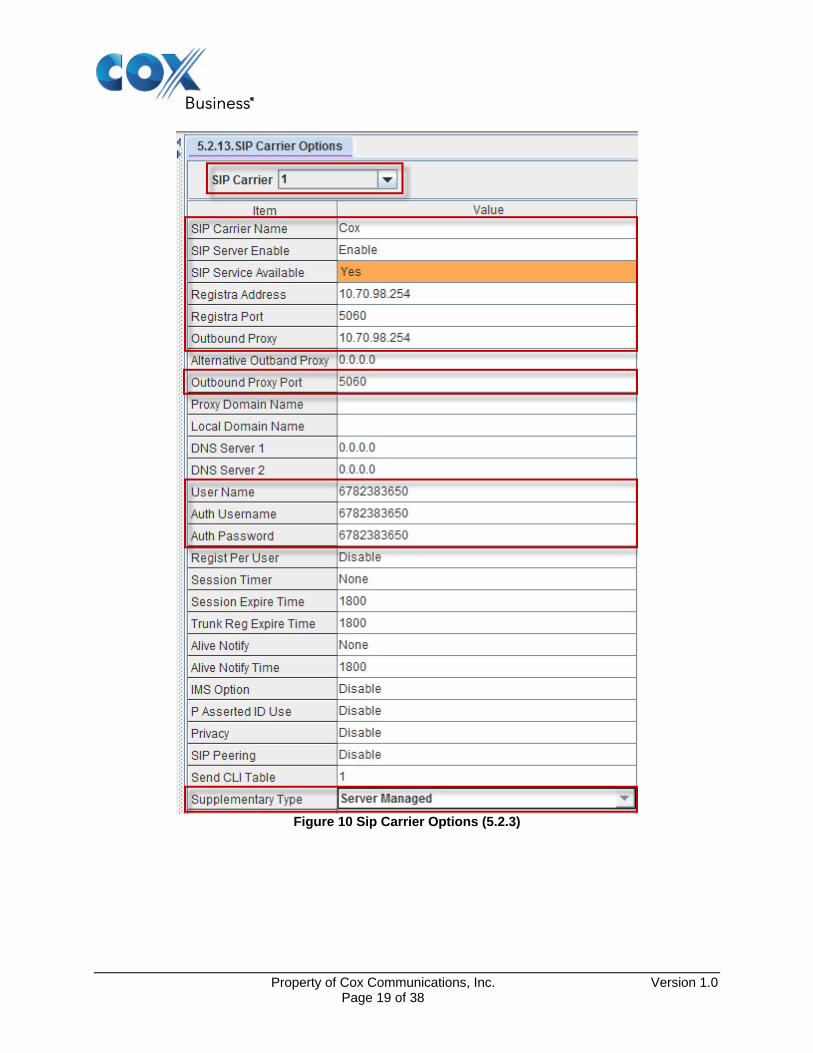
Figure 10 Sip Carrier Options (5.2.3)
Property of Cox Communications, Inc. Version 1.0 Page 19 of 38

Figure 11 Sip Carrier Options cont... (5.2.13)
Property of Cox Communications, Inc. Version 1.0 Page 20 of 38

6.3.5 Trunk Groups For the purpose of this example the user base of this PBX uses the access code of 9 to make a call to the PSTN. The Numbering Plan for the system is found in 2.8.0. The numbering plan has Sip Trunk numbers that will be used in 4.1.2 also the trunk group number that is used as the access code is defined in 2.8.0 as well. The number 9 is the trunk group number, this is set in 2.8.0 under TRK-GRP. When an extension user makes a call to the PSTN 9 will be dialed to access the trunk. The user will then dial a 10 digit number or a 1 + 10 digit number.
1. Navigate to Configuration > Numbering Plan > Numbering Plan (2.8.0)
6. Set Cabinet to All from the drop down menu. This will bring up a list of the Numbering Plan for the IP-PBX.
2. Scroll the list down until you find the Cabinet TRK-GRP
3. For Channel 1 Trunk Group Enter 9 for the Tel Number
4. Click Save
Figure 12 TRK-GRP (2.8.0)
Property of Cox Communications, Inc. Version 1.0 Page 21 of 38
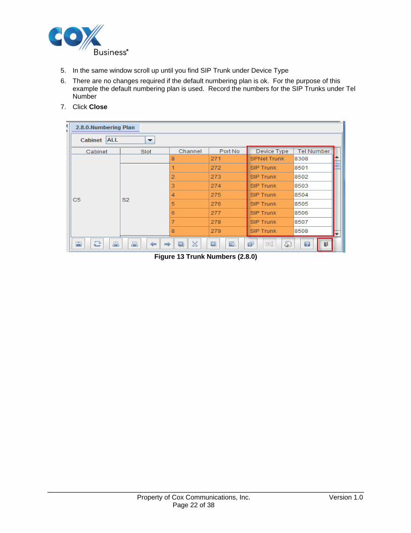
5. In the same window scroll up until you find SIP Trunk under Device Type
6. There are no changes required if the default numbering plan is ok. For the purpose of this example the default numbering plan is used. Record the numbers for the SIP Trunks under Tel Number
7. Click Close
Figure 13 Trunk Numbers (2.8.0)
Property of Cox Communications, Inc. Version 1.0 Page 22 of 38

8. The number of trunks that can be used is determined from Figure 8 reference SIP Stack > SIP Trunk> Max Count = 4. This is determined by the lincense that was purchased from the IP-PBX vendor.
9. Navigate to Group & Table > Grouping > Trunk Groups (4.1.2). Find Group 9. Notice that the 9 cannot be modified.
10. Set Group Type: SIP
11. Set Group Mode: Sequential
12. Add SIP Trunk Members 8501 – 8504
13. Click Save
Figure 14 Trunk Groups (4.1.2)
6.3.6 Assign Station Name Assign station name to be displayed on the phone. This view has several more columns to the right that are all at their default values.
1. Navigate to Configuration > Port Configuration > Port Common Data (2.4.2) scroll down until you locate the Tel Number you are working with
2. For this example we are using ext. 3201 and 3202
3. Assign the Name for each extension that you are using.
4. Click Save
Property of Cox Communications, Inc. Version 1.0 Page 23 of 38

Figure 15 Port Common Data (2.4.2)
6.3.7 Pickup Group Station Assignment/Call ID block
1. Navigate to Configuration > Station Port Configuration > Station Data (2.5.1) scroll down until you locate the Tel Number(s) you are working with
2. In the “Pickup Group“ column input the Pickup Group number that will be assigned to the extension numbers that are being provisiond.
3. To Block Caller ID for an extension set NO under “CLI Send“.
4. Click Save
Figure 16 Station Data (2.5.1)
Property of Cox Communications, Inc. Version 1.0 Page 24 of 38
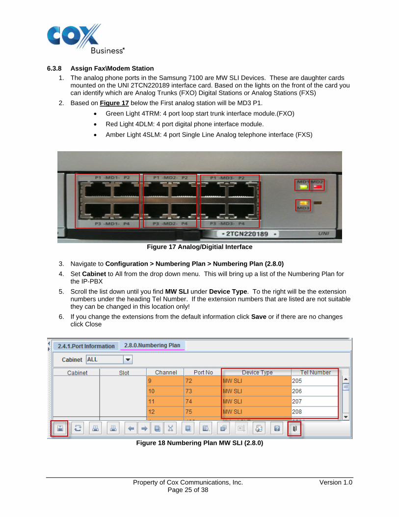
6.3.8 Assign Fax\Modem Station
1. The analog phone ports in the Samsung 7100 are MW SLI Devices. These are daughter cards mounted on the UNI 2TCN220189 interface card. Based on the lights on the front of the card you can identify which are Analog Trunks (FXO) Digital Stations or Analog Stations (FXS)
2. Based on Figure 17 below the First analog station will be MD3 P1.
Green Light 4TRM: 4 port loop start trunk interface module.(FXO)
Red Light 4DLM: 4 port digital phone interface module.
Amber Light 4SLM: 4 port Single Line Analog telephone interface (FXS)
Figure 17 Analog/Digitial Interface
3. Navigate to Configuration > Numbering Plan > Numbering Plan (2.8.0)
4. Set Cabinet to All from the drop down menu. This will bring up a list of the Numbering Plan for the IP-PBX
5. Scroll the list down until you find MW SLI under Device Type. To the right will be the extension numbers under the heading Tel Number. If the extension numbers that are listed are not suitable they can be changed in this location only!
6. If you change the extensions from the default information click Save or if there are no changes click Close
Figure 18 Numbering Plan MW SLI (2.8.0)
Property of Cox Communications, Inc. Version 1.0 Page 25 of 38

7. Navigate to Configuration > Station Port Configuration > SLI Data (2.5.7)
8. Scroll the list down until Tel Number 205 is visible
9. Under ISDN Service set Voice to FAX3
NOTE*** In this software release FAX3 has no impact but in future release it will control fax setup. This setting also works for a FXS used as a MODEM.
Figure 19 SLI Data (2.5.7)
6.3.9 Station Groups Station Groups are used to set up Simultaneous and Sequential ring groups. Station Groups are also used in the setup of Auto Attendant. The Auto Attendant will be explained in Section 6.3.13
Property of Cox Communications, Inc. Version 1.0 Page 26 of 38

1. Navigate to Group & Table > Grouping > Station Groups (4.1.1).
2. For this example Group 500 will be the Simultaneous Ring Group
3. Set Ring Mode: Uncondition
4. Set Group Name: All At Once is used for this example.
5. Towards the bottom of Figure 20 set 201 and 3202 as part of Group 500
6. For this example Group 501 will be the Sequential Ring Group
7. Set Ring Mode: Sequential
8. Set Group Name: Sequential is used in this example.
9. Towards the bottom of Figure 20 set the order that the phones should ring. In this example 3202 will ring first and 201 will ring second.
10. Click Save
Figure 20 Station Groups (4.1.1)
Property of Cox Communications, Inc. Version 1.0 Page 27 of 38

6.3.10 Account Codes There are two different types of Account Codes in the Samsung 7100. They are ACCT Verified and ACCT No Verified. For purpose of this example ACCT Verified will be explained.
1. Navigate to Group & Table > Account/Authorize Code > Forced Code (4.5.1)
2. Scroll the list down until the exension that will be assigned “ACCT Verified“ is reached.
3. Via the pull down menu select ACCT Verified. In this example extension 3202 is used.
4. Click Save
Figure 21 Forced Code (4.5.1)
5. Navigate to Group & Table > Account/Authorize Code > Account Code (4.5.2)
6. For number 1 under Entry No enter a 1-12 digit Account Code. For this example 123456 is used.
7. Click Save
Figure 22 Account Code (4.5.2)
Property of Cox Communications, Inc. Version 1.0 Page 28 of 38
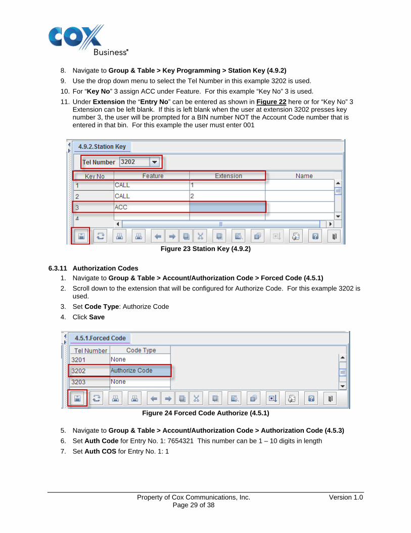
8. Navigate to Group & Table > Key Programming > Station Key (4.9.2)
9. Use the drop down menu to select the Tel Number in this example 3202 is used.
10. For “Key No” 3 assign ACC under Feature. For this example “Key No” 3 is used.
11. Under Extension the “Entry No” can be entered as shown in Figure 22 here or for “Key No” 3 Extension can be left blank. If this is left blank when the user at extension 3202 presses key number 3, the user will be prompted for a BIN number NOT the Account Code number that is entered in that bin. For this example the user must enter 001
Figure 23 Station Key (4.9.2)
6.3.11 Authorization Codes
1. Navigate to Group & Table > Account/Authorization Code > Forced Code (4.5.1)
2. Scroll down to the extension that will be configured for Authorize Code. For this example 3202 is used.
3. Set Code Type: Authorize Code
4. Click Save
Figure 24 Forced Code Authorize (4.5.1)
5. Navigate to Group & Table > Account/Authorization Code > Authorization Code (4.5.3)
6. Set Auth Code for Entry No. 1: 7654321 This number can be 1 – 10 digits in length
7. Set Auth COS for Entry No. 1: 1
Property of Cox Communications, Inc. Version 1.0 Page 29 of 38

Figure 25 Authorization Code (4.5.3)
8. Navigate to Configuration > Numbering Plan > Numbering Plan (2.8.0)
9. Set Cabinet to FEATURES from the drop down menu. This will bring up a list of Features under the column Slot.
10. Scroll down until AUTH is shown
11. Record the information under Tel Number for AUTH. If this number is acceptable click Close if this number requires changing, change the number and click Save. For this example * is used.
Figure 26 Numbering Plan Features
6.3.12 Allow External Forward
1. Navigate to Features > Timer/Option Features > UCD Forward/Wakeup Options (5.14.16)
2. Set Intercom External Forward: On This allows stations to call forward calls to PSTN.
3. All other options in this table are default
4. Click Save
Property of Cox Communications, Inc. Version 1.0 Page 30 of 38

Figure 27 UCD Forward Wakeup Options (5.14.6)
6.3.13 Auto Attendant
1. Navigate to VMAA > Open Block Table > Dial (8.1.4). This is to create the PSTN number so that it may be dialed via a single digit is pressed.
2. Click Add a new dialog window will appear named New Block
3. Set Block Name: Dial Block
4. Set Label Name: DialOffPrim is used for our example.
5. Click Save
Property of Cox Communications, Inc. Version 1.0 Page 31 of 38

Figure 28 New Block (8.1.4)
6. Once Save is pressed
7. Click Add a new dialog window will appear named Dial Block (OffPrim)
8. Set Number: 6782344101# This number is for example only
9. Set Station Type: Off Premise
10. Click Save&Exit
Figure 29 Dial Block(DialOffPrim)
Property of Cox Communications, Inc. Version 1.0 Page 32 of 38

11. Navigate to VMAA > Open Block Table > Menu (8.1.13).
12. Double click on Day Main
13. Click on Menu Input Processor
14. Set No. 6 For Event to 4 Set Action Goto Type DAL Target name select DialOffPrim. DialOffPrim is created in Section 6.3.13 steps 1 – 10. Now when a user dials the Auto Attendant number and presses the digit 4 the call will be sent to 6782344101.
15. Use modify the Auto Attendant as required
16. Click Save&Exit
Figure 30 Menu Block (Day Main)
Property of Cox Communications, Inc. Version 1.0 Page 33 of 38

6.4 Samsung 7100 Dial Plan Configuration For purpose of this example the Samsung 7100 is configured to dial 9 which is the access code for the SIP trunk. Setting up dial 9 access is covered in Section 6.3.5. The steps below give detailed step by step instructions for Inbound and out bound calls.
6.4.1 Incoming Routing To provision DID numbers in Samsung 7100 is a very simple process. The steps below define this process. The DID numbers that are used below are test numbers. Use only the range that is assigned to you from your Cox representative
1. Navigate to Call Routing > Incoming > DID Ringing (3.2.3)
2. For this example “Entry No” 1 – 6 will be populated and described below. Each Entry will be associated with a extension or a group
3. Set “Entry No“ 1 Incoming Digits: 6782383651 to the right under “1“ enter 3202
4. Repeat Step 3 for “Entry No” 2 – 6
When 6782383651 is received the call terminates to extension 3202
When 6782383652 is received the call terminates to extension 201
When 6782383654 is received the call terminates to group 501 Figure 20
When 6782383655 is received the call terminates to group 500 Figure 20
When 6782383673 is received the call terminates to Fax 205
When 6782383674 is received the call terminates to AA group 502 Figure 20
5. Click Save
Figure 31 DID Ringing (3.2.3)
Property of Cox Communications, Inc. Version 1.0 Page 34 of 38

6.4.2 Outgoing Dial Plan
The dial plan consists of what is allowed or denied. The method, in which the IP-PBX’s dial plan is documented, is to deny the numbers that should not be allowed out of the IP-PBX. That which is not explicitly denied is allowed.
1. Navigate to Group & Table > Class Of Service> Port Class (4.7.1)
2. Scroll down until the extension that is being configured appears under “Tel Number“ for this example we are using extension 3202
3. Set 3202: 1 under column “1” The “1” represents Class Of Service (COS) 1 The Gui is incorrectly worded. The Gui states “Ring Plan” Should be worded COS
Figure 32 Port Class (4.7.1)
4. Navigate to Group & Table > Class Of Service> COS Contents (4.7.2)
5. By default all COS’s use “Toll Level” A. For COS 01 change the “Toll Level” to B
6. Click Save
Figure 33 COS Contents (4.7.2)
Property of Cox Communications, Inc. Version 1.0 Page 35 of 38

7. Extension 3202 has been assigned COS 1 with Toll Level B. The goal now is to deny extension 3202 from dialing any 1900 numbers.
8. Navigate to Group & Table > Toll Restriction > Toll Deny Table (4.8.1)
9. Set “Entry No“:1 1900X
10. Set Toll Deny Table B for “Entry No“ 1 to Yes
11. Click Save
Figure 34 Toll Deny Table (4.8.1)
12. Now when station 3202 dials 1900-xxx-xxxx the call is blocked and a message shows on the phone that reads Toll Restricted.
13. The Toll Allow (4.8.2) table is used to override the Toll Deny Table (4.8.1) Figure xx. For this example 19005551212 will be allowed and all other 900 numbers will be blocked.
14. Navigate to Group & Table > Toll Restriction > Toll Deny Table (4.8.1)
15. Set “Entry No“:1 19005551212
16. Set Toll Allow Table B for “Entry No“ 1 to Yes
Figure 35 Toll Allow Table (4.8.2)
Property of Cox Communications, Inc. Version 1.0 Page 36 of 38

17. Now if extension 3202 dials 19005551212 the call completes.
18. A summary of the call permisions for extension 3202 is 1900 calls are denied with the exception of 19005551212. All other calls are allowed.
6.4.3 Send CLI Number The Calling Line ID (CLID) is configured to send phone user’s 10-digit DID number
1. Navigate to Configuration > Port Configuration > Send CLI Number (2.4.3)
2. Scroll down to the extension numbers that are being configured. In this example we are using extension 3201 and extension 3202
3. For extension 3201 Set 6782383652 in the column to the right
4. For extension 3202 Set 6782383651 in the column to the right
5. Click Save
Figure 36 Send CLI Number (2.4.3)
Property of Cox Communications, Inc. Version 1.0 Page 37 of 38

Property of Cox Communications, Inc. Version 1.0 Page 38 of 38
6.4.4 Calling Line ID Spoofing Calling ID Spoofing is the practice of sending a CLID that is not within the Cox assigned DID telephone number range(s). A legitimate use of CLID spoofing is the PBX customer wants to display their toll free number on non-emergency PBX originated calls such the dialed party can call the company back. To enable CLID spoofing support, the PBX customer must:
1. Contact your Cox sales representative to request spoofed CLID support on the Cox network, otherwise Cox will block calls that present a spoofed CLID.
2. Enter the toll free or other telephone number instead of the 10-digit DID number to be displayed for each extension in Figure 36 above.