single output uch models · output configuration: unipolar single output maximum rated output:...
TRANSCRIPT
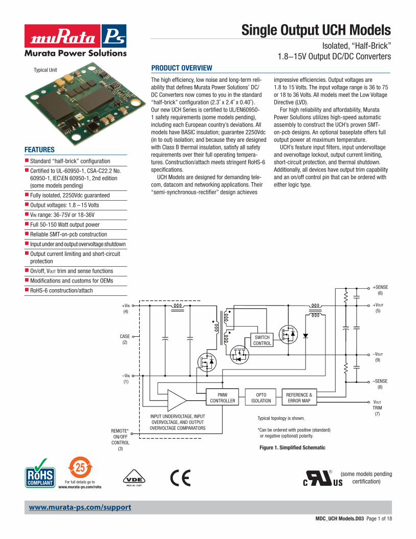
Figure 1. Simplified Schematic
–VIN
(1)
+VIN
(4)
CASE(2)
REMOTE* ON/OFF
CONTROL(3)
PMWCONTROLLER
OPTOISOLATION
REFERENCE &ERROR MAP
SWITCHCONTROL
INPUT UNDERVOLTAGE, INPUTOVERVOLTAGE, AND OUTPUT
OVERVOLTAGE COMPARATORS
+VOUT
(5)
–VOUT
(9)
VOUT
TRIM(7)
+SENSE(6)
–SENSE(8)
Typical topology is shown.
*Can be ordered with positive (standard) or negative (optional) polarity.
Typical Unit
FEATURESnStandard “half-brick” configuration
nCertified to UL-60950-1, CSA-C22.2 No. 60950-1, IEC\EN 60950-1, 2nd edition (some models pending)
nFully isolated, 2250Vdc guaranteed
nOutput voltages: 1.8 – 15 Volts
nVin range: 36-75V or 18-36V
nFull 50-150 Watt output power
nReliable SMT-on-pcb construction
n Input under and output overvoltage shutdown
nOutput current limiting and short-circuit protection
nOn/off, VOUT trim and sense functions
nModifications and customs for OEMs
nRoHS-6 construction/attach
The high efficiency, low noise and long-term reli-ability that defines Murata Power Solutions’ DC/DC Converters now comes to you in the standard “half-brick” configuration (2.3˝ x 2.4˝ x 0.40˝) . Our new UCH Series is certified to UL/EN60950-1 safety requirements (some models pending), including each European country’s deviations. All models have BASIC insulation; guarantee 2250Vdc (in to out) isolation; and because they are designed with Class B thermal insulation, satisfy all safety requirements over their full operating tempera-tures. Construction/attach meets stringent RoHS-6 specifications.
UCH Models are designed for demanding tele-com, datacom and networking applications. Their “semi-synchronous-rectifier” design achieves
impressive efficiencies. Output voltages are 1.8 to 15 Volts. The input voltage range is 36 to 75 or 18 to 36 Volts. All models meet the Low Voltage Directive (LVD).
For high reliability and affordability, Murata Power Solutions utilizes high-speed automatic assembly to construct the UCH’s proven SMT-on-pcb designs. An optional baseplate offers full output power at maximum temperature.
UCH’s feature input filters, input undervoltage and overvoltage lockout, output current limiting, short-circuit protection, and thermal shutdown. Additionally, all devices have output trim capability and an on/off control pin that can be ordered with either logic type.
PRODUCT OVERVIEW
REG.-Nr. C457
(some models pending certification)
www.murata-ps.com
www.murata-ps.com/support
For full details go towww.murata-ps.com/rohs
Single Output UCH ModelsIsolated, “Half-Brick”
1.8−15V Output DC/DC Converters
MDC_UCH Models.D03 Page 1 of 18
Output Configuration: Unipolar Single Output
Maximum Rated Output: Current in Amps
Half-brick package
Nominal Output Voltage
Input Voltage Range: D24 = 18-36 Volts D48 = 36-75 Volts
U CH - / D48-30 N5 B -
PART NUMBER STRUCTURE
H C
On/Off Control Logic P = Positive logic (standard for D24, optional for D48) N = Negative logic (standard for D48, optional for D24)
Optional Baseplate Blank = No Baseplate, standard B = Baseplate installed, optional quantity order
RoHS Hazardous Materials Compliance C = RoHS-6 (does not claim EU RoHS exemption 7b–lead in solder), standard Y = RoHS-5 (with lead), optional, special order
Note:Some model number combinations may not be available. Please contact Murata Power Solutions.
Conformal Coating Option Blank = No coating, standard H = Coating added, optional* (built to order; contact Murata Power Solutions for MOQ and lead times.)
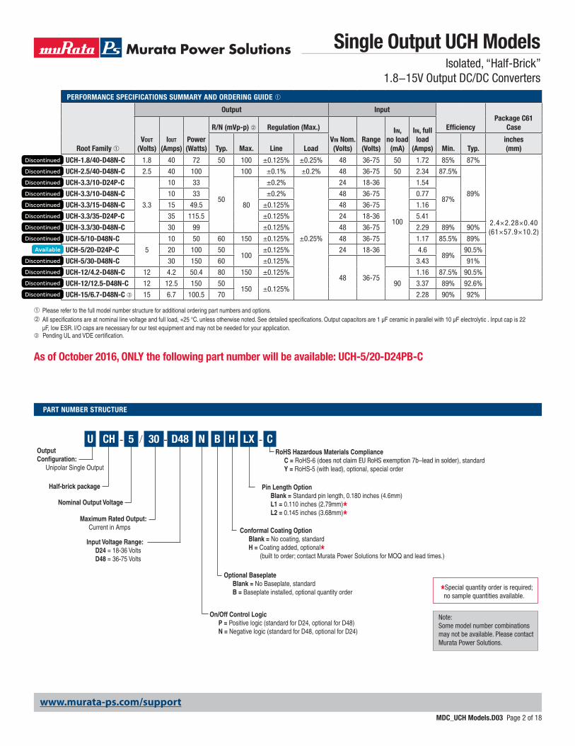
PERFORMANCE SPECIFICATIONS SUMMARY AND ORDERING GUIDE ➀
Root Family ➀
Output Input
EfficiencyPackage C61
Case
Vout (Volts)
Iout
(Amps)Power (Watts)
R/N (mVp-p) ➁ Regulation (Max.)
Vin Nom. (Volts)
Range (Volts)
Iin, no load
(mA)
Iin, full load
(Amps)Typ. Max. Line Load Min. Typ.inches (mm)
UCH-1.8/40-D48N-C 1.8 40 72 50 100 ±0.125% ±0.25% 48 36-75 50 1.72 85% 87%
2.4×2.28×0.40 (61×57.9×10.2)
UCH-2.5/40-D48N-C 2.5 40 100
50
100 ±0.1% ±0.2% 48 36-75 50 2.34 87.5%
89%
UCH-3.3/10-D24P-C
3.3
10 33
80
±0.2%
±0.25%
24 18-36
100
1.54
87%UCH-3.3/10-D48N-C 10 33 ±0.2% 48 36-75 0.77
UCH-3.3/15-D48N-C 15 49.5 ±0.125% 48 36-75 1.16
UCH-3.3/35-D24P-C 35 115.5 ±0.125% 24 18-36 5.41
UCH-3.3/30-D48N-C 30 99 ±0.125% 48 36-75 2.29 89% 90%
UCH-5/10-D48N-C
5
10 50 60 150 ±0.125% 48 36-75 1.17 85.5% 89%
UCH-5/20-D24P-C 20 100 50100
±0.125% 24 18-36 4.689%
90.5%
UCH-5/30-D48N-C 30 150 60 ±0.125%
48 36-75
3.43 91%
UCH-12/4.2-D48N-C 12 4.2 50.4 80 150 ±0.125%
90
1.16 87.5% 90.5%
UCH-12/12.5-D48N-C 12 12.5 150 50150 ±0.125%
3.37 89% 92.6%
UCH-15/6.7-D48N-C ➂ 15 6.7 100.5 70 2.28 90% 92%
➀ Please refer to the full model number structure for additional ordering part numbers and options.➁All specifications are at nominal line voltage and full load, +25 °C. unless otherwise noted. See detailed specifications. Output capacitors are 1 µF ceramic in parallel with 10 µF electrolytic . Input cap is 22
µF, low ESR. I/O caps are necessary for our test equipment and may not be needed for your application.➂ Pending UL and VDE certification.
Pin Length Option Blank = Standard pin length, 0.180 inches (4.6mm) L1 = 0.110 inches (2.79mm)* L2 = 0.145 inches (3.68mm)*
LX
*Special quantity order is required; no sample quantities available.
As of October 2016, ONLY the following part number will be available: UCH-5/20-D24PB-C
www.murata-ps.com/support
Single Output UCH ModelsIsolated, “Half-Brick”
1.8−15V Output DC/DC Converters
MDC_UCH Models.D03 Page 2 of 18

FUNCTIONAL SPECIFICATIONS ➀
UCH-1.8/40-D48 UCH-2.5/40-D48 UCH-3.3/10-D24 UCH-3.3/10-D48 UCH-3.3/15-D48 UCH-3.3/35-D24 UCH-3.3/30-D48
Input
Input voltage range See ordering guide
Start-up threshold, Volts 34 34 16 34 34 16 34
Undervoltage shutdown, V
32 31 15 31 31 15 31
Overvoltage shutdown none
Reflected (back) ripple cur-rent, mA pk-pk
10 20 10 15 15 15 10
Input Current
Full load conditions See ordering guide.
Inrush transient, A2sec 0.05
Output short circuit, mA 50
Low line (Vin = min.), Amps 2.30 1.54 2.06 1.03 1.54 7.21 3.09
Standby mode, mA (Off, UV, OT shutdown)
2 10 8
Internal input filter type Pi L-C
External recommended fast blow fuse, Amps
10 3 5 3 3 12.5 7.5
Reverse polarity protection
None. Install external fuse.
Remote On/Off Control
Positive logic (P model suffix)
OFF = Ground pin to +1V max. ON = Open or +3.5 to +13.5V max
Negative logic (N model suffix)
OFF = Open or +2.5V to +15V max. ON = –0.1V to +0.8V max
Current, mA 1
Output
Voltage output range See ordering guide.
Voltage output accuracy ±1% of Vnom (50% load)
Adjustment range –10 to +10% of Vnom.
Temperature coefficient over oper. temp. range
±0.02% of Vout range per °C
Minimum loading No minimum loading.
Remote sense compensation
+10%.
Ripple/noise (20 MHz bandwidth)
See ordering guide.
Line/Load regulation See ordering guide.
Efficiency See ordering guide.
Maximum capacitive loading, Low ESR <0.02Ω max., resistive load, μF
10,000 max.
17
www.murata-ps.com/support
Single Output UCH ModelsIsolated, “Half-Brick”
1.8−15V Output DC/DC Converters
MDC_UCH Models.D03 Page 3 of 18
UCH-5/10-D48 UCH-5/20-D24 UCH-5/30-D48 UCH-12/4.2-D48 UCH-12/12.5-D48 UCH-15/6.7-D48
Input
Input voltage range See ordering guide.
Start-up threshold, Volts 34 16 35 35 35 35
Undervoltage shutdown, V
33 15 34 33.5 33.5 33
Overvoltage shutdown none
Reflected (back) ripple cur-rent, mA pk-pk
15 20 15 20 20 20
Input Current
Full load conditions See ordering guide.
Inrush transient, A2sec 0.05
Output short circuit, mA 50
Low line (Vin = min.), Amps 1.54 6.17 4.63 1.51 4.47 3.06
Standby mode, mA (Off, UV, OT shutdown)
4 10 4 1
Internal input filter type Pi L-C Pi L-C
External recommended fast blow fuse, Amps
10 10 7.5 10 7.5
Reverse polarity protection
None. Install external fuse.
Remote On/Off Control
Positive logic (P model suffix)
OFF = Ground pin to +1V max. ON = Open or +3.5 to +15V max
Negative logic (N model suffix)
OFF = Open or +2.5V to +15V max. ON = –0.1V to +0.8V max
Current, mA 1
Output
Voltage output range See ordering guide.
Voltage output accuracy ±1% of Vnom.
Adjustment range –10 to +10% of Vnom.
Temperature coefficient over oper. Temp. range
±0.02% of Vout range per °C
Minimum loading No minimum loading.
Remote sense compensation
+10%.
Ripple/noise (20 MHz bandwidth)
See ordering guide.
Line/Load regulation See ordering guide.
Efficiency See ordering guide.
Maximum capacitive loading, Low ESR <0.02Ω max., resistive load, μF
10,000 10,000 max. 20,000 max. 5000 10,000 1,000
17
www.murata-ps.com/support
Single Output UCH ModelsIsolated, “Half-Brick”
1.8−15V Output DC/DC Converters
MDC_UCH Models.D03 Page 4 of 18
UCH-1.8/40-D48 UCH-2.5/40-D48 UCH-3.3/10-D24 UCH-3.3/10-D48 UCH-3.3/15-D48 UCH-3.3/35-D24 UCH-3.3/30-D48
Isolation Voltage
Input to Output, Volts min. 2250
Input to baseplate, Volts min. 1500
Baseplate to output, Volts min. 1500
Isolation resistance, MΩ 100
Isolation capacitance, pF 1000
Isolation safety rating Basic insulation
Current limit inception (98% of Vout, after warmup), Amps
59 max. 49 15 15 19 40 35
Short circuit protection method Current limiting, hiccup autorestart. Remove overload for recovery.
Short circuit current, Amps 5
Short circuit duration Output may be shorted continuously to ground (no damage).
Overvoltage protection, Volts (via magnetic feedback)
2.7 max. 3.75 max. 4.95 V max 4.62 max. 4.95 max.
Prebiased Startup Starts if external voltage is less than Vnom.
Dynamic characteristics
Dynamic load response (50-75-50% load step)
100 µSec to ±1% of final value
100 µSec to ±1% of final value
200 µSec to ±1% of final value
200 µSec to ±1% of final value
200 µSec to ±1% of final value
200 µSec to ±1% of final value
200 µSec to ±1% of final value
Start-up time
Vin to Vout regulated, mSec 10 max.
Remote On/Off to Vout regulated, mSec
10 max.
Switching frequency, KHz 360 420 ± 40 330 ± 40
Environmental
Calculated MTBF 1.6M hrs. TBD 1.8M hrs. TBD
Operating ambient temperature range, °C (with derating)
−40 to +85 (See Derating Curves)
Operating PC board temperature, °C
−40 to +110
Storage temperature range, °C −55 to +125
Thermal protection/shutdown, °C +115 +115 +120
Relative humidity To +85°C/85%, non-condensing
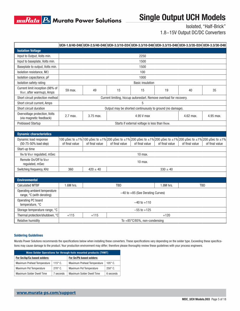
Soldering Guidelines
Murata Power Solutions recommends the specifications below when installing these converters. These specifications vary depending on the solder type. Exceeding these specifica-
tions may cause damage to the product. Your production environment may differ; therefore please thoroughly review these guidelines with your process engineers.
Wave Solder Operations for through-hole mounted products (THMT)
For Sn/Ag/Cu based solders: For Sn/Pb based solders:
Maximum Preheat Temperature 115° C. Maximum Preheat Temperature 105° C.
Maximum Pot Temperature 270° C. Maximum Pot Temperature 250° C.
Maximum Solder Dwell Time 7 seconds Maximum Solder Dwell Time 6 seconds
www.murata-ps.com/support
Single Output UCH ModelsIsolated, “Half-Brick”
1.8−15V Output DC/DC Converters
MDC_UCH Models.D03 Page 5 of 18

UCH-5/10-D48 UCH-5/20-D24 UCH-5/30-D48 UCH-12/4.2-D48 UCH-12/12.5-D48 UCH-15/6.7-D48
Isolation Voltage
Input to Output, Volts min. 2250
Input to baseplate, Volts min. 1500
Baseplate to output, Volts min. 1500
Isolation resistance, MΩ 100
Isolation capacitance, pF 1000
Isolation safety rating Basic insulation
Miscellaneous
Current limit inception (98% of Vout, after warmup), Amps
13 26 35 5.4 14.5 7.4
Short circuit protection method Current limiting, hiccup autorestart. Remove overload for recovery.
Short circuit current, Amps 5
Short circuit duration Output may be shorted continuously to ground (no damage).
Overvoltage protection, Volts (via magnetic feedback)
7.75 max. 7.5 max. 7.5 18 max. 16.8 max. 17.5
Prebiased Startup Starts if external voltage is less than Vnom.
Dynamic characteristics
Dynamic load response (50-75-50% load step)
200 µSec to ±1% of final value
200 µSec to ±1% of final value
200 µSec to ±1% of final value
250 µSec to ±1% of final value
250 µSec to ±1% of final value
250 µSec to ±1% of final value
Start-up time
Vin to Vout regulated, mSec 10 max.
Remote On/Off to Vout regulated, mSec
10 max.
Switching frequency, KHz 300 ± 30 330 ± 40 300 ± 30 335 ± 35 335 ± 35 350 ± 40
Environmental
Calculated MTBF 1.6M hours TBD 1.9M hours 1.6M hours TBD
Operating ambient temperature range, °C (with derating)
−40 to +85 (See Derating Curves)
Operating PC board temperature, °C
−40 to +110
Storage temperature range, °C −55 to +125
Thermal protection/shutdown, °C +120 +115
Relative humidity To +85°C/85%, non-condensing
www.murata-ps.com/support
Single Output UCH ModelsIsolated, “Half-Brick”
1.8−15V Output DC/DC Converters
MDC_UCH Models.D03 Page 6 of 18
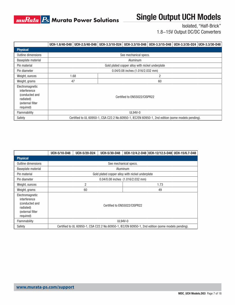
UCH-1.8/40-D48 UCH-2.5/40-D48 UCH-3.3/10-D24 UCH-3.3/10-D48 UCH-3.3/15-D48 UCH-3.3/35-D24 UCH-3.3/30-D48
Physical
Outline dimensions See mechanical specs.
Baseplate material Aluminum
Pin material Gold plated copper alloy with nickel underplate
Pin diameter 0.04/0.08 inches (1.016/2.032 mm)
Weight, ounces 1.68 2
Weight, grams 47 60
Electromagnetic interference (conducted and radiated) (external filter required)
Certified to EN55022/CISPR22
Flammability UL94V-0
Safety Certified to UL 60950-1, CSA C22.2 No.60950-1, IEC/EN 60950-1, 2nd edition (some models pending).
UCH-5/10-D48 UCH-5/20-D24 UCH-5/30-D48 UCH-12/4.2-D48 UCH-12/12.5-D48 UCH-15/6.7-D48
Physical
Outline dimensions See mechanical specs.
Baseplate material Aluminum
Pin material Gold plated copper alloy with nickel underplate
Pin diameter 0.04/0.08 inches (1.016/2.032 mm)
Weight, ounces 2 1.73
Weight, grams 60 49
Electromagnetic interference (conducted and radiated) (external filter required)
Certified to EN55022/CISPR22
Flammability UL94V-0
Safety Certified to UL 60950-1, CSA C22.2 No.60950-1, IEC/EN 60950-1, 2nd edition (some models pending).
www.murata-ps.com/support
Single Output UCH ModelsIsolated, “Half-Brick”
1.8−15V Output DC/DC Converters
MDC_UCH Models.D03 Page 7 of 18
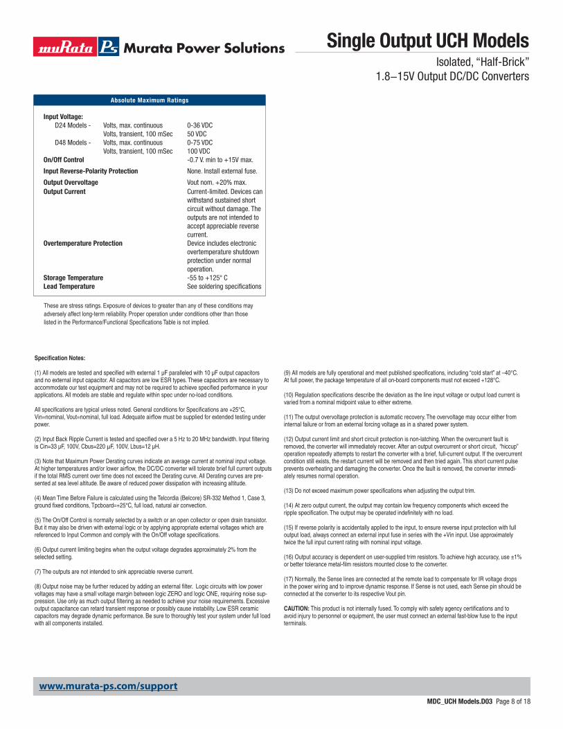
Specification Notes:
(1) All models are tested and specified with external 1 µF paralleled with 10 µF output capacitors and no external input capacitor. All capacitors are low ESR types. These capacitors are necessary to accommodate our test equipment and may not be required to achieve specified performance in your applications. All models are stable and regulate within spec under no-load conditions.
All specifications are typical unless noted. General conditions for Specifications are +25°C, Vin=nominal, Vout=nominal, full load. Adequate airflow must be supplied for extended testing under power.
(2) Input Back Ripple Current is tested and specified over a 5 Hz to 20 MHz bandwidth. Input filtering is Cin=33 µF, 100V, Cbus=220 μF, 100V, Lbus=12 µH.
(3) Note that Maximum Power Derating curves indicate an average current at nominal input voltage. At higher temperatures and/or lower airflow, the DC/DC converter will tolerate brief full current outputs if the total RMS current over time does not exceed the Derating curve. All Derating curves are pre-sented at sea level altitude. Be aware of reduced power dissipation with increasing altitude.
(4) Mean Time Before Failure is calculated using the Telcordia (Belcore) SR-332 Method 1, Case 3, ground fixed conditions, Tpcboard=+25°C, full load, natural air convection.
(5) The On/Off Control is normally selected by a switch or an open collector or open drain transistor. But it may also be driven with external logic or by applying appropriate external voltages which are referenced to Input Common and comply with the On/Off voltage specifications.
(6) Output current limiting begins when the output voltage degrades approximately 2% from the selected setting.
(7) The outputs are not intended to sink appreciable reverse current.
(8) Output noise may be further reduced by adding an external filter. Logic circuits with low power voltages may have a small voltage margin between logic ZERO and logic ONE, requiring noise sup-pression. Use only as much output filtering as needed to achieve your noise requirements. Excessive output capacitance can retard transient response or possibly cause instability. Low ESR ceramic capacitors may degrade dynamic performance. Be sure to thoroughly test your system under full load with all components installed.
(9) All models are fully operational and meet published specifications, including “cold start” at –40°C. At full power, the package temperature of all on-board components must not exceed +128°C.
(10) Regulation specifications describe the deviation as the line input voltage or output load current is varied from a nominal midpoint value to either extreme.
(11) The output overvoltage protection is automatic recovery. The overvoltage may occur either from internal failure or from an external forcing voltage as in a shared power system.
(12) Output current limit and short circuit protection is non-latching. When the overcurrent fault is removed, the converter will immediately recover. After an output overcurrent or short circuit, “hiccup” operation repeatedly attempts to restart the converter with a brief, full-current output. If the overcurrent condition still exists, the restart current will be removed and then tried again. This short current pulse prevents overheating and damaging the converter. Once the fault is removed, the converter immedi-ately resumes normal operation.
(13) Do not exceed maximum power specifications when adjusting the output trim.
(14) At zero output current, the output may contain low frequency components which exceed the ripple specification. The output may be operated indefinitely with no load.
(15) If reverse polarity is accidentally applied to the input, to ensure reverse input protection with full output load, always connect an external input fuse in series with the +Vin input. Use approximately twice the full input current rating with nominal input voltage.
(16) Output accuracy is dependent on user-supplied trim resistors. To achieve high accuracy, use ±1% or better tolerance metal-film resistors mounted close to the converter.
(17) Normally, the Sense lines are connected at the remote load to compensate for IR voltage drops in the power wiring and to improve dynamic response. If Sense is not used, each Sense pin should be connected at the converter to its respective Vout pin.
CAUTION: This product is not internally fused. To comply with safety agency certifications and to avoid injury to personnel or equipment, the user must connect an external fast-blow fuse to the input terminals.
Input Voltage: D24 Models - Volts, max. continuous 0-36 VDC Volts, transient, 100 mSec 50 VDC D48 Models - Volts, max. continuous 0-75 VDC Volts, transient, 100 mSec 100 VDCOn/Off Control -0.7 V. min to +15V max.
Input Reverse-Polarity Protection None. Install external fuse.
Output Overvoltage Vout nom. +20% max.Output Current Current-limited. Devices can withstand sustained short circuit without damage. The outputs are not intended to accept appreciable reverse current.Overtemperature Protection Device includes electronic overtemperature shutdown protection under normal operation.Storage Temperature -55 to +125° CLead Temperature See soldering specifications
These are stress ratings. Exposure of devices to greater than any of these conditions may adversely affect long-term reliability. Proper operation under conditions other than those listed in the Performance/Functional Specifications Table is not implied.
Absolute Maximum Ratings
www.murata-ps.com/support
Single Output UCH ModelsIsolated, “Half-Brick”
1.8−15V Output DC/DC Converters
MDC_UCH Models.D03 Page 8 of 18

Ou
tpu
t C
urr
ent
(Am
ps)
Ambient Temperature (°C)
400 lfm
200 lfm300 lfm
100 lfm
30
32
24
28
26
36
40
34
38
30 40 50 60 70 80
UCH-2.5/40-D48 Maximum Current Temperature Derating (at sea level)No baseplate, VIN = 48V, transverse airflow
10
15
20
25
30
35
40
45
30 35 40 45 50 55 60 65 70 75 80 85
400 lfm
200 lfm300 lfm
100 lfm
UCH-1.8/40-D48 Maximum Current Temperature Derating (at sea level)No baseplate, VIN = 48V, airflow is from VIN to VOUT
Ou
tpu
t C
urr
ent
(Am
ps)
Ambient Temperature (°C)
VIN = 48V
VIN = 75V
Eff
icie
ncy
(%
)
Po
wer
Dis
sip
atio
n (
Wat
ts)
Load Current (Amps)
VIN = 36V
65
75
60
70
85
80
90
63 9 12 15 18 21 24 27
95
Power Dissipation (VIN = 48V)
0
1
3
5
2
4
6
8
10
7
9
UCH-2.5/40-D48 Efficiency and Power Dissipation vs Line Voltage and Load Current @25˚C
4 8 12 16 20 24 28 32 36 40
UCH-1.8/40-D48 Efficiency and Power Dissipation vs Line Voltage and Load Current @25˚C
VIN = 48VVIN = 75V
Eff
icie
ncy
(%
)
Po
wer
Dis
sip
atio
n (
Wat
ts)
Load Current (Amps)
VIN = 36V
Power Dissipation (VIN = 48V)
40
45
50
55
60
65
70
75
80
85
90
95
0
1.1
2.2
3.3
4.4
5.5
6.6
7.7
8.8
9.9
11
12.1
VIN = 48V
VIN = 36V
Eff
icie
ncy
(%
)
Load Current (Amps)
VIN = 75V
43 565
70
75
80
85
90
95
6 7 8 9 10
Power Dissipation (VIN = 48V)
UCH-3.3/10-D48 Maximum Current Temperature Deratingvs Line Voltage and Load Current @25˚C
Po
wer
Dis
sip
atio
n (
Wat
ts)
3.2
3.4
3.6
3.8
4
2.8
3.0
VIN = 24V
VIN = 18V
Eff
icie
ncy
(%
)
Load Current (Amps)
VIN = 36V75
70
65
85
80
90
43 5 6 7 8 9 10
Power Dissipation (VIN = 24V)
UCH-3.3/10-D24 Efficiency and Power Dissipation vs Line Voltage and Load Current @25˚C
Po
wer
Dis
sip
atio
n (
Wat
ts)
6
1
2
3
4
5
TYPICAL PERFORMANCE DATA
www.murata-ps.com/support
Single Output UCH ModelsIsolated, “Half-Brick”
1.8−15V Output DC/DC Converters
MDC_UCH Models.D03 Page 9 of 18

Ou
tpu
t C
urr
ent
(Am
ps)
Ambient Temperature (°C)
400 lfm
200 lfm300 lfm
100 lfm
30 40 50 60 70
20
24
8
16
12
32
40
28
36
UCH-3.3/35-D24 Maximum Current Temperature Derating (at sea level)No baseplate, VIN = 24V, transverse airflow
VIN = 24V
VIN = 18V
Eff
icie
ncy
(%
)
Load Current (Amps)
VIN = 36V
75
70
85
80
90
63 9 12 15 18 21 27 3024 33
95
Power Dissipation (VIN = 24V)
UCH-3.3/35-D24 Efficiency and Power Dissipation vs Line Voltage and Load Current @25˚C
Po
wer
Dis
sip
atio
n (
Wat
ts)
16
20
18
14
0
2
6
10
4
8
12
Ou
tpu
t C
urr
ent
(Am
ps)
Ambient Temperature (°C)
200 lfm
300 lfm
100 lfm
30 40 50 60 8070
26
27
25
24
23
29
31
28
30
UCH-3.3/30-D48 Maximum Current Temperature Derating (at sea level)No baseplate, VIN = 48V, transverse airflow
Eff
icie
ncy
(%
)
Load Current (Amps)
75
65
70
60
85
80
90
63 9 12 15 18 21 27 3024
95
Power Dissipation (VIN = 48V)VIN = 36V
VIN = 48V
VIN = 75V
UCH-3.3/30-D48 Efficiency and Power Dissipation vs Line Voltage and Load Current @25˚C
Po
wer
Dis
sip
atio
n (
Wat
ts)
0
1
3
5
2
4
6
8
10
7
9
Eff
icie
ncy
(%
)
Load Current (Amps)
VIN = 75V
75
85
80
90
43 5 6 7 8 9 11 1210 13 1514
95
Power Dissipation (VIN = 48V)
70
65
55
60
VIN = 48V
VIN = 36V
UCH-3.3/15-D48 Efficiency and Power Dissipation vs Line Voltage and Load Current @25˚C
Po
wer
Dis
sip
atio
n (
Wat
ts)
2
3
4
5
6
7
8
9
10
TYPICAL PERFORMANCE DATA
www.murata-ps.com/support
Single Output UCH ModelsIsolated, “Half-Brick”
1.8−15V Output DC/DC Converters
MDC_UCH Models.D03 Page 10 of 18

Ou
tpu
t C
urr
ent
(Am
ps)
Ambient Temperature (°C)
400 lfm200 lfm
30 40 50 60 70 80
14
16
12
10
20
18
300 lfm100 lfm
UCH-5/20-D24 Maximum Current Temperature Derating (at sea level)No baseplate, VIN = 24V, transverse airflow
VIN = 24V
VIN = 18V
Eff
icie
ncy
(%
)
Load Current (Amps)
VIN = 36V
75
70
85
80
90
63 9 12 15 18
95
Power Dissipation (VIN = 24V)
UCH-5/20-D24 Efficiency and Power Dissipation vs Line Voltage and Load Current @25˚C
Po
wer
Dis
sip
atio
n (
Wat
ts)
20
0
2
6
10
4
8
12
16
14
18
Ou
tpu
t C
urr
ent
(Am
ps)
Ambient Temperature (°C)
400 lfm200 lfm
30 40 50 60 70 80
18
22
14
10
30
26
300 lfm100 lfm
UCH-5/30-D48 Maximum Current Temperature Derating (at sea level)No baseplate, VIN = 48V, transverse airflow
Eff
icie
ncy
(%
)
Load Current (Amps)
75
70
85
80
90
63 9 12 1815 24 2721 30
95
VIN = 48V
VIN = 75V
VIN = 36V Power Dissipation (VIN = 48V)
UCH-5/30-D48 Efficiency and Power Dissipation vs Line Voltage and Load Current @25˚C
Po
wer
Dis
sip
atio
n (
Wat
ts)
0
4
8
12
16
20
30 40 50 60 70 80 850
0.5
1
1.5
2
2.5
3
3.5
4
4.5
UCH-12/4.2-D48 Maximum Current Temperature Derating at sea level(VIN = 48V, airflow direction from VIN to VOUT, no baseplate)
Ou
tpu
t C
urr
ent
(Am
ps)
Ambient Temperature (°C)
Natural Convection
0.42 0.84 1.26 1.68 2.1 2.52 2.94 3.36 3.78 4.2
01234567891011121314
656769717375777981838587899193
UCH-12/4.2-D48 Efficiency and Power Dissipation vs Line Voltage and Load Current @25˚C
Po
wer
Dis
sip
atio
n (
Wat
ts)
Eff
icie
ncy
(%
)
Load Current (Amps)
VIN = 75VVIN = 36V VIN = 48V
Power Dissipation (VIN = 48V)
TYPICAL PERFORMANCE DATA
www.murata-ps.com/support
Single Output UCH ModelsIsolated, “Half-Brick”
1.8−15V Output DC/DC Converters
MDC_UCH Models.D03 Page 11 of 18

Eff
icie
ncy
(%
)
Load Current (Amps)
75
65
70
85
80
90
2 3 4 5 5.54.53.52.51.51 6 6.5
100
95
Power Dissipation(VIN = 48V)
VIN = 48V
VIN = 75V
VIN = 36V
UCH-15/6.7-D48 Efficiency and Power Dissipation vs Line Voltage and Load Current @25˚C
Po
wer
Dis
sip
atio
n (
Wat
ts)
0
4
2
6
10
14
8
12
Ou
tpu
t C
urr
ent
(Am
ps)
Ambient Temperature (°C)
400 lfm200 lfm
30 40 50 60 70 80
4
5
2
3
1
0
7
6
300 lfm100 lfm
UCH-15/6.7-D48 Maximum Current Temperature Derating (at sea level)No baseplate, VIN = 48V, transverse airflow
Ou
tpu
t C
urr
ent
(Am
ps)
Ambient Temperature (°C)
400 lfm200 lfm
30 40 50 60 70 80
12.5
11.5
19.5
9.5
8.5
7.5
6.5
300 lfm100 lfm
UCH-12/12.5-D48 Maximum Current Temperature Derating (at sea level)No baseplate, VIN = 48V, transverse airflow
Eff
icie
ncy
(%
)
Load Current (Amps)
75
70
85
80
90
5 643 7 8 9 10 11 12
95
65
Power Dissipation (VIN = 48V)
VIN = 75VVIN = 48VVIN = 36V
UCH-12/12.5-D48 Efficiency and Power Dissipation vs Line Voltage and Load Current @25˚C
Po
wer
Dis
sip
atio
n (
Wat
ts)
6
10
4
8
12
16
20
14
18
TYPICAL PERFORMANCE DATA
www.murata-ps.com/support
Single Output UCH ModelsIsolated, “Half-Brick”
1.8−15V Output DC/DC Converters
MDC_UCH Models.D03 Page 12 of 18
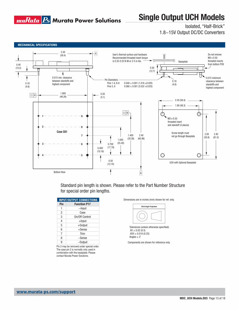
MECHANICAL SPECIFICATIONS
Bottom View
1
2
3
4 5
6
7
8
9
1.900(48.26)
2.30(58.4)
0.40(10.2)
0.18(4.6)
0.20(5.1)
0.015 min. clearancebetween standoffs andhighest component
0.400 (10.16)
0.700 (17.78)
0.50(12.70)
1.000 (25.40)
1.400 (35.56)
2.40(60.96)
Pin Diameters: Pins 1-4, 6-8 0.040 ± 0.001 (1.016 ±0.025) Pins 5, 9 0.080 ± 0.001 (2.032 ±0.025)
UCH with Optional Baseplate
0.18(4.6)
0.50(12.7)
2.40(61.0)
2.00(50.8)
1.90 (48.3)
2.30 (58.4)
0.015 minimumclearance betweenstandoffs andhighest component
Do not removeM3 x 0.50 threaded inserts from bottom PCB
User’s thermal surface and hardwareRecommended threaded insert torque is 0.35-0.55 N-M or 3-5 in-lbs.
M3 x 0.50 threaded insert and standoff (4 places)
Screw length mustnot go through Baseplate
Baseplate
Case C61
A
B
A
B
INPUT/OUTPUT CONNECTIONSPin Function P171 −Input2 Case3 On/Off Control4 +Input5 +Output6 +Sense7 Trim8 −Sense9 −Output
Third Angle Projection
Dimensions are in inches (mm) shown for ref. only.
Components are shown for reference only.
Tolerances (unless otherwise specified):.XX ± 0.02 (0.5).XXX ± 0.010 (0.25)Angles ± 2˚
Pin 2 may be removed under special order. The case pin 2 is normally only used in combination with the baseplate. Please contact Murata Power Solutions.
www.murata-ps.com/support
Standard pin length is shown. Please refer to the Part Number Structure for special order pin lengths.
Single Output UCH ModelsIsolated, “Half-Brick”
1.8−15V Output DC/DC Converters
MDC_UCH Models.D03 Page 13 of 18
Input FusingCertain applications and/or safety agencies may require fuses at the inputs of power conversion components. Fuses should also be used when there is the possibility of sustained input voltage reversal which is not current-limited. For greatest safety, we recommend a fast blow fuse installed in the ungrounded input supply line.
The installer must observe all relevant safety standards and regulations. For safety agency approvals, install the converter in compliance with the end-user safety standard, i.e. IEC/EN/UL 60950-1.
Input Reverse-Polarity ProtectionIf the input voltage polarity is reversed, an internal body diode will become forward biased and likely draw excessive current from the power source. If this source is not current-limited or the circuit appropriately fused, it could cause permanent damage to the converter. Please be sure to install a properly-rated external input fuse (see Specifications).
Input Under-Voltage Shutdown and Start-Up ThresholdUnder normal start-up conditions, converters will not begin to regulate properly until the ramping-up input voltage exceeds and remains at the Start-Up Threshold Voltage (see Specifications). Once operating, converters will not turn off until the input voltage drops below the Under-Voltage Shutdown Limit. Subsequent restart will not occur until the input voltage rises again above the Start-Up Threshold. This built-in hysteresis prevents any unstable on/off opera-tion at a single input voltage.
Users should be aware however of input sources near the Under-Voltage Shutdown whose voltage decays as input current is consumed (such as ca-pacitor inputs), the converter shuts off and then restarts as the external capaci-tor recharges. Such situations could oscillate. To prevent this, make sure the operating input voltage is well above the UV Shutdown voltage AT ALL TIMES.
Start-Up TimeAssuming that the output current is set at the rated maximum, the Vin to Vout Start-Up Time (see Specifications) is the time interval between the point when the ramping input voltage crosses the Start-Up Threshold and the fully loaded regulated output voltage enters and remains within its specified accuracy band. Actual measured times will vary with input source impedance, external input capacitance, input voltage slew rate and final value of the input voltage as it appears at the converter.
These converters include a soft start circuit to moderate the duty cycle of its PWM controller at power up, thereby limiting the input inrush current.
The On/Off Remote Control interval from On command to Vout regulated assumes that the converter already has its input voltage stabilized above the Start-Up Threshold before the On command. The interval is measured from the On command until the output enters and remains within its specified accuracy band. The specification assumes that the output is fully loaded at maximum rated current. Similar conditions apply to the On to Vout regulated specification such as external load capacitance and soft start circuitry.
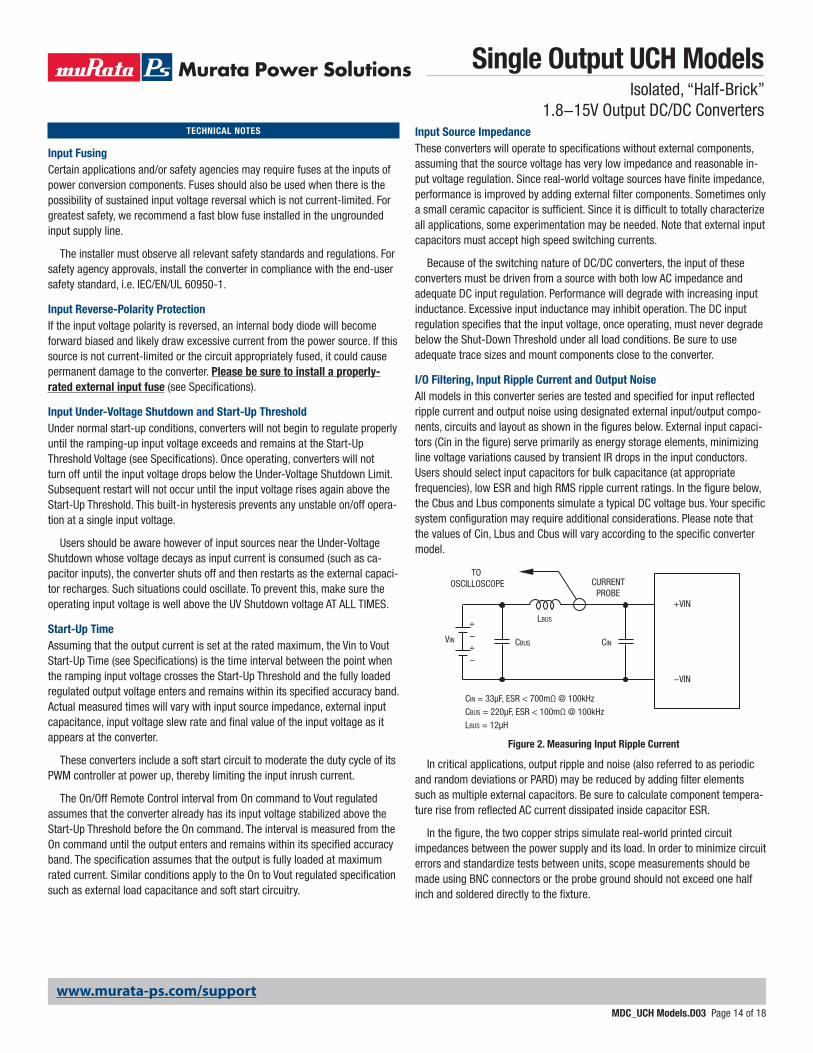
TECHNICAL NOTES Input Source ImpedanceThese converters will operate to specifications without external components, assuming that the source voltage has very low impedance and reasonable in-put voltage regulation. Since real-world voltage sources have finite impedance, performance is improved by adding external filter components. Sometimes only a small ceramic capacitor is sufficient. Since it is difficult to totally characterize all applications, some experimentation may be needed. Note that external input capacitors must accept high speed switching currents.
Because of the switching nature of DC/DC converters, the input of these converters must be driven from a source with both low AC impedance and adequate DC input regulation. Performance will degrade with increasing input inductance. Excessive input inductance may inhibit operation. The DC input regulation specifies that the input voltage, once operating, must never degrade below the Shut-Down Threshold under all load conditions. Be sure to use adequate trace sizes and mount components close to the converter.
I/O Filtering, Input Ripple Current and Output NoiseAll models in this converter series are tested and specified for input reflected ripple current and output noise using designated external input/output compo-nents, circuits and layout as shown in the figures below. External input capaci-tors (Cin in the figure) serve primarily as energy storage elements, minimizing line voltage variations caused by transient IR drops in the input conductors. Users should select input capacitors for bulk capacitance (at appropriate frequencies), low ESR and high RMS ripple current ratings. In the figure below, the Cbus and Lbus components simulate a typical DC voltage bus. Your specific system configuration may require additional considerations. Please note that the values of Cin, Lbus and Cbus will vary according to the specific converter model.
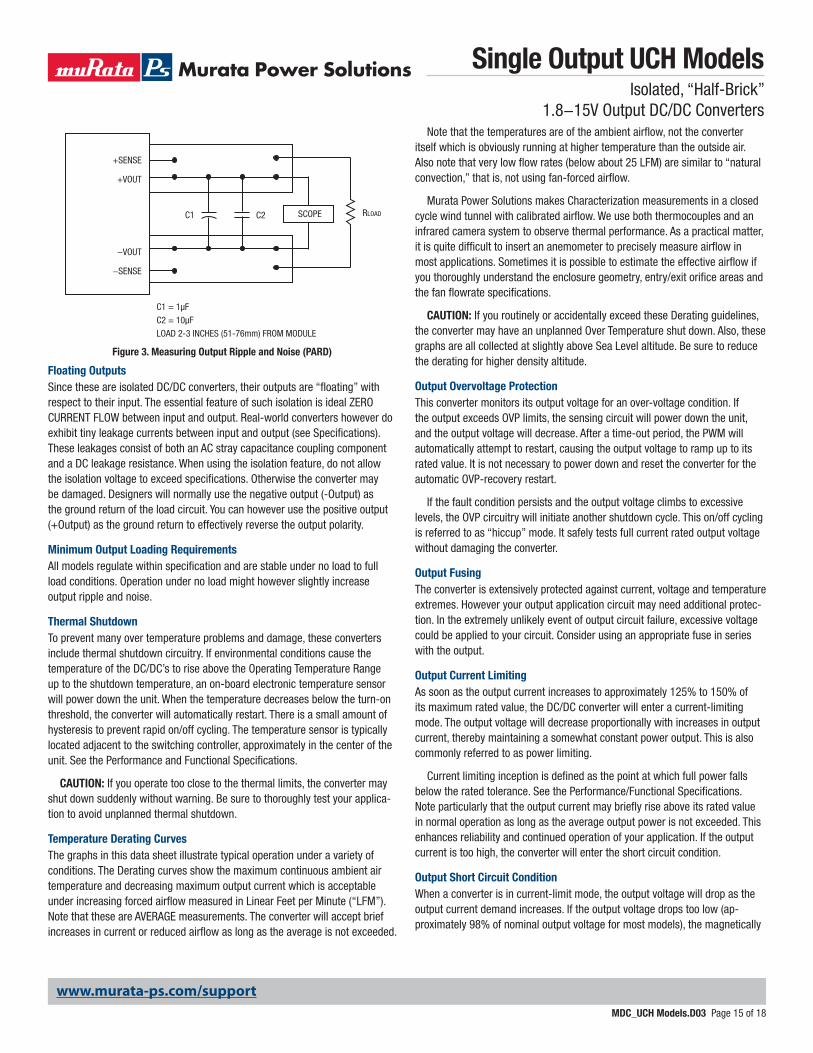
In critical applications, output ripple and noise (also referred to as periodic and random deviations or PARD) may be reduced by adding filter elements such as multiple external capacitors. Be sure to calculate component tempera-ture rise from reflected AC current dissipated inside capacitor ESR.
In the figure, the two copper strips simulate real-world printed circuit impedances between the power supply and its load. In order to minimize circuit errors and standardize tests between units, scope measurements should be made using BNC connectors or the probe ground should not exceed one half inch and soldered directly to the fixture.
Figure 2. Measuring Input Ripple Current
CINVIN CBUS
LBUS
CIN = 33µF, ESR < 700mΩ @ 100kHz
CBUS = 220µF, ESR < 100mΩ @ 100kHz
LBUS = 12µH
+VIN
−VIN
CURRENTPROBE
TO OSCILLOSCOPE
+–+–
www.murata-ps.com/support
Single Output UCH ModelsIsolated, “Half-Brick”
1.8−15V Output DC/DC Converters
MDC_UCH Models.D03 Page 14 of 18
Floating OutputsSince these are isolated DC/DC converters, their outputs are “floating” with respect to their input. The essential feature of such isolation is ideal ZERO CURRENT FLOW between input and output. Real-world converters however do exhibit tiny leakage currents between input and output (see Specifications). These leakages consist of both an AC stray capacitance coupling component and a DC leakage resistance. When using the isolation feature, do not allow the isolation voltage to exceed specifications. Otherwise the converter may be damaged. Designers will normally use the negative output (-Output) as the ground return of the load circuit. You can however use the positive output (+Output) as the ground return to effectively reverse the output polarity.
Minimum Output Loading RequirementsAll models regulate within specification and are stable under no load to full load conditions. Operation under no load might however slightly increase output ripple and noise.
Thermal ShutdownTo prevent many over temperature problems and damage, these converters include thermal shutdown circuitry. If environmental conditions cause the temperature of the DC/DC’s to rise above the Operating Temperature Range up to the shutdown temperature, an on-board electronic temperature sensor will power down the unit. When the temperature decreases below the turn-on threshold, the converter will automatically restart. There is a small amount of hysteresis to prevent rapid on/off cycling. The temperature sensor is typically located adjacent to the switching controller, approximately in the center of the unit. See the Performance and Functional Specifications.
CAUTION: If you operate too close to the thermal limits, the converter may shut down suddenly without warning. Be sure to thoroughly test your applica-tion to avoid unplanned thermal shutdown.
Temperature Derating CurvesThe graphs in this data sheet illustrate typical operation under a variety of conditions. The Derating curves show the maximum continuous ambient air temperature and decreasing maximum output current which is acceptable under increasing forced airflow measured in Linear Feet per Minute (“LFM”). Note that these are AVERAGE measurements. The converter will accept brief increases in current or reduced airflow as long as the average is not exceeded.
Note that the temperatures are of the ambient airflow, not the converter itself which is obviously running at higher temperature than the outside air. Also note that very low flow rates (below about 25 LFM) are similar to “natural convection,” that is, not using fan-forced airflow.
Murata Power Solutions makes Characterization measurements in a closed cycle wind tunnel with calibrated airflow. We use both thermocouples and an infrared camera system to observe thermal performance. As a practical matter, it is quite difficult to insert an anemometer to precisely measure airflow in most applications. Sometimes it is possible to estimate the effective airflow if you thoroughly understand the enclosure geometry, entry/exit orifice areas and the fan flowrate specifications.
CAUTION: If you routinely or accidentally exceed these Derating guidelines, the converter may have an unplanned Over Temperature shut down. Also, these graphs are all collected at slightly above Sea Level altitude. Be sure to reduce the derating for higher density altitude.
Output Overvoltage ProtectionThis converter monitors its output voltage for an over-voltage condition. If the output exceeds OVP limits, the sensing circuit will power down the unit, and the output voltage will decrease. After a time-out period, the PWM will automatically attempt to restart, causing the output voltage to ramp up to its rated value. It is not necessary to power down and reset the converter for the automatic OVP-recovery restart.
If the fault condition persists and the output voltage climbs to excessive levels, the OVP circuitry will initiate another shutdown cycle. This on/off cycling is referred to as “hiccup” mode. It safely tests full current rated output voltage without damaging the converter.
Output FusingThe converter is extensively protected against current, voltage and temperature extremes. However your output application circuit may need additional protec-tion. In the extremely unlikely event of output circuit failure, excessive voltage could be applied to your circuit. Consider using an appropriate fuse in series with the output.
Output Current LimitingAs soon as the output current increases to approximately 125% to 150% of its maximum rated value, the DC/DC converter will enter a current-limiting mode. The output voltage will decrease proportionally with increases in output current, thereby maintaining a somewhat constant power output. This is also commonly referred to as power limiting.
Current limiting inception is defined as the point at which full power falls below the rated tolerance. See the Performance/Functional Specifications. Note particularly that the output current may briefly rise above its rated value in normal operation as long as the average output power is not exceeded. This enhances reliability and continued operation of your application. If the output current is too high, the converter will enter the short circuit condition.
Output Short Circuit ConditionWhen a converter is in current-limit mode, the output voltage will drop as the output current demand increases. If the output voltage drops too low (ap-proximately 98% of nominal output voltage for most models), the magnetically
Figure 3. Measuring Output Ripple and Noise (PARD)
C1
C1 = 1µF
C2 = 10µF
LOAD 2-3 INCHES (51-76mm) FROM MODULE
C2 RLOADSCOPE
+VOUT
+SENSE
−SENSE
−VOUT
www.murata-ps.com/support
Single Output UCH ModelsIsolated, “Half-Brick”
1.8−15V Output DC/DC Converters
MDC_UCH Models.D03 Page 15 of 18
coupled voltage used to develop primary side voltages will also drop, thereby shutting down the PWM controller. Following a time-out period, the PWM will restart, causing the output voltage to begin ramping up to its appropriate value. If the short-circuit condition persists, another shutdown cycle will initiate. This rapid on/off cycling is called “hiccup mode”. The hiccup cycling reduces the average output current, thereby preventing excessive internal temperatures and/or component damage. A short circuit can be tolerated indefinitely.
The “hiccup” system differs from older latching short circuit systems because you do not have to power down the converter to make it restart. The system will automatically restore operation as soon as the short circuit condi-tion is removed.
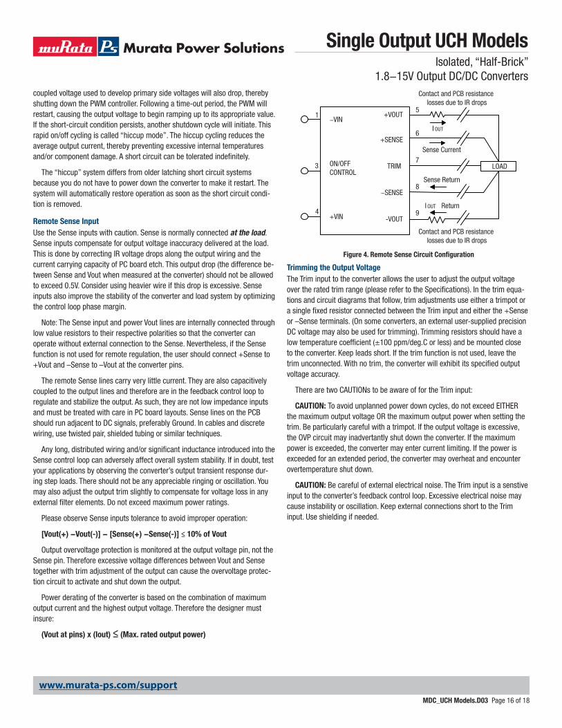
Remote Sense InputUse the Sense inputs with caution. Sense is normally connected at the load. Sense inputs compensate for output voltage inaccuracy delivered at the load. This is done by correcting IR voltage drops along the output wiring and the current carrying capacity of PC board etch. This output drop (the difference be-tween Sense and Vout when measured at the converter) should not be allowed to exceed 0.5V. Consider using heavier wire if this drop is excessive. Sense inputs also improve the stability of the converter and load system by optimizing the control loop phase margin.
Note: The Sense input and power Vout lines are internally connected through low value resistors to their respective polarities so that the converter can operate without external connection to the Sense. Nevertheless, if the Sense function is not used for remote regulation, the user should connect +Sense to +Vout and –Sense to –Vout at the converter pins.
The remote Sense lines carry very little current. They are also capacitively coupled to the output lines and therefore are in the feedback control loop to regulate and stabilize the output. As such, they are not low impedance inputs and must be treated with care in PC board layouts. Sense lines on the PCB should run adjacent to DC signals, preferably Ground. In cables and discrete wiring, use twisted pair, shielded tubing or similar techniques.
Any long, distributed wiring and/or significant inductance introduced into the Sense control loop can adversely affect overall system stability. If in doubt, test your applications by observing the converter’s output transient response dur-ing step loads. There should not be any appreciable ringing or oscillation. You may also adjust the output trim slightly to compensate for voltage loss in any external filter elements. Do not exceed maximum power ratings.
Please observe Sense inputs tolerance to avoid improper operation:
[Vout(+) −Vout(-)] − [Sense(+) −Sense(-)] ≤ 10% of Vout
Output overvoltage protection is monitored at the output voltage pin, not the Sense pin. Therefore excessive voltage differences between Vout and Sense together with trim adjustment of the output can cause the overvoltage protec-tion circuit to activate and shut down the output.
Power derating of the converter is based on the combination of maximum output current and the highest output voltage. Therefore the designer must insure:
(Vout at pins) x (Iout) ≤ (Max. rated output power)
Trimming the Output VoltageThe Trim input to the converter allows the user to adjust the output voltage over the rated trim range (please refer to the Specifications). In the trim equa-tions and circuit diagrams that follow, trim adjustments use either a trimpot or a single fixed resistor connected between the Trim input and either the +Sense or –Sense terminals. (On some converters, an external user-supplied precision DC voltage may also be used for trimming). Trimming resistors should have a low temperature coefficient (±100 ppm/deg.C or less) and be mounted close to the converter. Keep leads short. If the trim function is not used, leave the trim unconnected. With no trim, the converter will exhibit its specified output voltage accuracy.
There are two CAUTIONs to be aware of for the Trim input:
CAUTION: To avoid unplanned power down cycles, do not exceed EITHER the maximum output voltage OR the maximum output power when setting the trim. Be particularly careful with a trimpot. If the output voltage is excessive, the OVP circuit may inadvertantly shut down the converter. If the maximum power is exceeded, the converter may enter current limiting. If the power is exceeded for an extended period, the converter may overheat and encounter overtemperature shut down.
CAUTION: Be careful of external electrical noise. The Trim input is a senstive input to the converter’s feedback control loop. Excessive electrical noise may cause instability or oscillation. Keep external connections short to the Trim input. Use shielding if needed.
Figure 4. Remote Sense Circuit Configuration
LOAD
5
8
7
6
9
Contact and PCB resistance losses due to IR drops
Contact and PCB resistance losses due to IR drops
+VOUT
+SENSE
TRIM
−SENSE
-VOUT
−VIN
ON/OFFCONTROL
+VIN
1
3
4
Sense Current
I OUT
Sense Return
I OUT Return
www.murata-ps.com/support
Single Output UCH ModelsIsolated, “Half-Brick”
1.8−15V Output DC/DC Converters
MDC_UCH Models.D03 Page 16 of 18

Trim Equations
VNOM is the nominal, untrimmed output voltage.VOUT is the desired new output voltage.
Do not exceed the specified trim range or maximum power ratingswhen adjusting trim. Use 1% precision resistors mounted closeto the converter on short leads.
Trim DownConnect trim resistor between
trim pin and −Sense
∆1RTrimDn (kΩ) = − 2
Where,∆ = VNOMINAL − VOUT
VNOMINAL
Trim UpConnect trim resistor between
trim pin and +Sense
1.225 × ∆VNOMINAL × (1 + ∆)RTrimUp (kΩ) = − 2− 1
∆
Where,∆ = VOUT − VNOMINAL
VNOMINAL
Figure 5. Trim Connections Using A Trimpot
Figure 7. Trim Connections to Decrease Output VoltagesFigure 6. Trim Connections to Increase Output Voltages
LOAD
+OUT+IN
–IN
ON/OFF TRIM
+SENSE
–OUT
–SENSE
LOAD RTRIM DOWN
+OUT+IN
–IN
ON/OFF TRIM
+SENSE
–OUT
–SENSE
LOAD RTRIM UP
+OUT+IN
–IN
ON/OFF TRIM
+SENSE
–OUT
–SENSE
Trim Equations
Trim Circuits
www.murata-ps.com/support
Single Output UCH ModelsIsolated, “Half-Brick”
1.8−15V Output DC/DC Converters
MDC_UCH Models.D03 Page 17 of 18

Remote On/Off ControlOn the input side, a remote On/Off Control can be ordered with either logic type.
Positive: Standard models are enabled when the On/Off pin is left open or is pulled high to +Vin with respect to –Vin. An internal bias current causes the open pin to rise to approximately +15V. Some models will also turn on at lower intermediate voltages (see Specifications). Positive-logic devices are disabled when the On/Off is grounded or brought to within a low voltage (see Specifica-tions) with respect to –Vin.
Negative: Optional negative-logic devices are on (enabled) when the On/Off is grounded or brought to within a low voltage (see Specifications) with respect to –Vin. The device is off (disabled) when the On/Off is left open or is pulled high to approximately +15V with respect to –Vin.
Dynamic control of the On/Off function should be able to sink appropriate signal current when brought low and withstand appropriate voltage when brought high. Be aware too that there is a finite time in milliseconds (see Specifications) between the time of On/Off Control activation and stable, regulated output. This time will vary slightly with output load type and current and input conditions.
There are several CAUTIONs for the On/Off Control:
CAUTION: While it is possible to control the On/Off with external logic if you carefully observe the voltage levels, the preferred circuit is either an open drain/open collector transistor, a switch or a relay (which can thereupon be controlled by logic) returned to negative Vin.
CAUTION: Do not apply voltages to the On/Off pin when there is no input power voltage. Otherwise the converter may be permanently damaged.
Output Capacitive LoadThese converters do not require external capacitance added to achieve rated specifications. Users should only consider adding capacitance to reduce switch-ing noise and/or to handle spike current step loads. Install only enough ca-pacitance to achieve noise objectives. Excess external capacitance may cause regulation problems, slower transient response and possible instability. Proper wiring of the Sense inputs will improve these factors under capacitive load.
The maximum rated output capacitance and ESR specification is given for a capacitor installed immediately adjacent to the converter. Any extended output wiring or smaller wire gauge or less ground plane may tolerate somewhat high-er capacitance. Also, capacitors with higher ESR may use a larger capacitance.
Product AdaptationsMurata Power Solutions offers several variations of our core product family. These products are available under scheduled quantity orders and may also include separate manufacturing documentation from a mutually-agreeable Product Specification. Since these product adaptations largely share a common parts list, similar specifications and test methods with their root products, they are provided at excellent costs and delivery. Please contact MPS for details.
As of this date, the following products are available:
UCH-3.3/30-D48NBHL2-Y
UCH-5/10-D48NBHL2-Y
UCH-3.3/15-D48NBHL2-Y
UCH-3.3/35-D24NBHL2-Y
These are all negative On/Off logic, baseplate installed, conformal coating added, 3.68mm pin length, and RoHS-5 hazardous substance compliance (with lead).
www.murata-ps.com/support
Murata Power Solutions, Inc. makes no representation that the use of its products in the circuits described herein, or the use of other technical information contained herein, will not infringe upon existing or future patent rights. The descriptions contained herein do not imply the granting of licenses to make, use, or sell equipment constructed in accordance therewith. Specifications are subject to change without notice. © 2017 Murata Power Solutions, Inc.
Murata Power Solutions, Inc. 11 Cabot Boulevard, Mansfield, MA 02048-1151 U.S.A.ISO 9001 and 14001 REGISTERED
This product is subject to the following operating requirements and the Life and Safety Critical Application Sales Policy: Refer to: http://www.murata-ps.com/requirements/
Single Output UCH ModelsIsolated, “Half-Brick”
1.8−15V Output DC/DC Converters
MDC_UCH Models.D03 Page 18 of 18