ac power regulators apr-d series (single-phase) · 2020-01-10 · phase control, cycle control, and...
TRANSCRIPT

HES170
Power Supply and Voltage Control
AC Power Regulators
APR-D Series (Single-phase)


Also applicable to control of inductive load and primary control of transformers and rectifiers, through continuous comb tooth pulse control. Optimum for light modulation of LED illumination (for phase control).Note: When the rated voltage is applied, the load shall flow the minimum load current or more.
Being able to switch the waveform control method among phase control, cycle control, and phase angle proportion control.
Space saving is possible due to a class-minimal dense array(minimum interval in width: 2 mm)
Output voltage 71%V, α = 90°
Output voltage 71%V, (1/2)
Phase control (0 to 100%)
Cycle control (Intermittent control)
100Acommunication board supplied
45A / 60Acontrol input connector supplied
20Astandard
Single AC power regulators
series
RPDE

Catalog DisclaimerThe information contained in this catalog does not constitute an express or implied warranty of quality, any warranty of merchantability of fitness for a particular purpose is hereby disclaimed.
Since the user's product information, specific use application, and conditions of use are all outside of Fuji Electric FA Components & Systems'control, it shall be the responsibility of the user to determine the suitability of any of the products mentioned for the user's application.
One Year Limited WarrantyThe products identified in this catalog shall be sold pursuant to the terms and conditions identified in the"Conditions of Sale" issued by Fuji Electric FA with each order confirmation.
Except to the extent otherwise provided for in the Conditions of Sale issued by Fuji Electric FA, Fuji Electric FA warrants that the Fuji Electric FA products identified in this catalog shall be free from significant defects in materials and workmanship provided the product has not been: 1) repaired or altered by others than Fuji Electric FA; 2) subjected to negligence, accident, misuse, or damage by circumstances beyond Fuji Electric FA's control; 3) improperly operated, maintained or stored; or 4) used in other than normal use or service. This warranty shall apply only to defects appearing within one (1) year from the date of shipment by Fuji Electric FA, and in such case, only if such defects are reported to Fuji Electric FA within thirty (30) days of discovery by purchaser. Such notice should be submitted in writing to Fuji Electric FA at 5-7, Nihonbashi Odemma-cho, Chuo-ku, Tokyo, Japan. The sole and exclusive remedy with respected to the above warranty whether such claim is based on warranty, contract, negligence, strict liability or any other theory, is limited to the repair or replacement of such product or, at Fuji Electric FA's option reimbursement by Fuji Electric FA of the purchase price paid to Fuji Electric FA for the particular product. Fuji Electric FA does not make any other representations or warranties, whether oral or in writing, expressed or implied, including but not limited to any warranty regarding merchantability or fitness for a particular purpose. Except as provided in the Conditions of Sale, no agent or representative of Fuji Electric FA is authorized to modify the terms of this warranty in writing or orally. In no event shall Fuji Electric FA be liable for special, indirect or consequential damages, including but not limited to, loss of use of the product, other equipment, plant and power system which is installed with the product, loss of profits or revenues, cost of capital, or claims against the purchaser or user of the product by its customers resulting from the use of information, recommendations and descriptions contained herein. The purchaser agrees to pass on to its customers and users, in writing at the time inquiries and orders are received by buyer, Fuji Electric FA's warranty as set forth above.

1
AC Power RegulatorsAPR-D Series (Single-phase)
Page
Features ............................................................................................................................................................................................... 2
Type number nomenclature .................................................................................................................................................................. 3
Types and ratings ................................................................................................................................................................................. 3
Specifications ....................................................................................................................................................................................... 4
Wiring diagram ..................................................................................................................................................................................... 5
Other options ........................................................................................................................................................................................ 6
Dimensions ........................................................................................................................................................................................... 9

2Fuji Electric FA Components & Systems Co., Ltd./D & C Catalog
Information subject to change without notice
AC Power RegulatorsAPR-D series
20 A standard
45 A/ 60 A control input connector supplied
(Specification code: ZB1)
100 A communication board supplied
(Specification code: ZAM)
Single AC power regulators APR-D series
n DescriptionThe single-phase APR-D series of products are successors of αB and αC.Whereas their functions and performance have been largely improved due to incorporation of a CPU, space saving, less wiring, and inexpensive cost have been achieved.
n Features•Alsoapplicabletocontrolofinductiveloadandprimarycon-
trol of transformers and rectifiers, through continuous comb tooth pulse control.
Optimum for light modulation of LED illumination (for phase control).
Note: When the rated voltage is applied, the load shall flow the minimum load current or more.
•Beingabletoswitchthewaveformcontrolmethodamongphase control, cycle control, and phase angle proportion con-trol.
Output voltage 71%V,α = 90°
Output voltage 71%V,(1/2)
Phase control (0 to 100%)
Cycle control (Intermittent control)
•Thestandardconfigurationdoesnotincludeacontrolinputconnector. (Less wiring, low cost)
For auto setting or manual setting only, it is possible to adjust the device by changing the function of the control input termi-nal block.
MO5V4C
Control input/ power terminal
2
Manual settingdevice3 1
MO5V4C
Temperaturecontroller
+ --+
Gradientsetting
Control input/ power terminal
4-20mA DC 1-5V DC
MO5V4C
+ -
Temperaturecontroller
Control input/ power terminal
1-5/0-5V DC
Temperaturecontroller
+ -
MO5V4C
Control input/ power terminal
4-20mA DC
(6o.06:n-Am)
6o.06:n-Am2b.02:5Vm0( )
(6o.06:n-Am)
Note: The factory defaults are n-Am for 6o.06 and Aod for 2b.02. The parentheses show function codes and terminal functions.
(6o.06:n-m_)
•Spacesavingispossibleduetoaclass-minimaldensearray(minimum interval in width: 2 mm)
•Baseloadsetting,digitalsettingsincludinggradientsetting,and monitor functions are available as part of the standard configuration.
Monitor mode 2b. 01 m_vr
Aod
Function code
Setting mode
Function code data
Operation example
Pressing and holding for more than one second causes data to be automatically sent.
Pressing and holding for one second or no operation for 20 seconds
•Allowssoftstarttime,softuptime,andsoftdowntimetobediscretely set in the range of 0 seconds to100.0 seconds.
•Performsautoidentificationof100to240VACand50/60Hzwith respect to control power
•Asacontrolmethod,currentlimitcontrolandautomaticcurrent feedback control are available.
You can also detect heater disconnection (cycle control: load opening).
Note: It is possible to detect disconnection of one to three lines in an alloy heater where there are small changes in resistance depending on the temperature.
•Allowscommunicationcontrolasanoptionalfunction. Option type of the main unit: ZAP: Up to 50 units can be operated in parallel.
For cycle control, a flicker prevention function is avail-able.
ZAM:Varioussettingsandmonitorsarepossiblebymeansof RS485 (Modbus RTU).
•AllmodelssatisfyCEmarking.

3Fuji Electric FA Components & Systems Co., Ltd./D & C CatalogInformation subject to change without notice
AC Power RegulatorsAPR-D series
RPD E 2 0 6 0 − T 1 − Z B 1 (Note 1)
Product categoryProduct CodeAPR-D series RPD
Number of phasesNumber of phases CodeSingle phase E
Input voltageInput voltage Code100-240V 2
Rated currentRated current Code20A 02045A 04560A 060100A 100
Setting device (Note 2)
Setting device CodeNon BlankSetting device: 1 set 1Setting device: 2 sets 2Setting device: 3 sets 3
Control methodControl method CodeNo feedback function TAC CLR AAC ACR plus AC CLR B
CLR: Current limit regulatorACR: Automotic current regurator
SpecificationsSpecifications CodeStandard BlankOption of the main unit Z** (Note 3)
Note 1: For the order codes which are blank, put no space, immediately followed by a hyphen.Note 2: One set of setting devices is composed of a variable resistor, nameplate, control knob, and attachment sheet. The format of a separate order is "RPD001". This is not shown as
the type of the main unit.Note 3: For options of the main unit, it is possible to specify multiple specification items like RPDE2020-T1-ZAMB1.
Option specification names Description TypeCommunication board (For parallel run) Mounting a communication board for parallel run, equipped with a flicker prevention function (Note 4) RPDE2□□□-□■-ZAPCommunication board (For network connections) Mounting a communication board for Modbus RTU RPDE2□□□-□■-ZAMControl input connector A connector is supplied to support functions including manual, gradient setting input (external
attachment) and alarm output. (Note 5)RPDE2□□□-□■-ZB1
Main-circuit power On soft start Soft start through main-circuit power On is possible. (Pure metal load can be handled.) (Note 6) RPDE2□□□-□■-Z45Note 4: The parallel run function provided by this communication board is not compatible with models other than the APR-D series.Note 5: A connector set (socket: built-in/ plug: supplied) for a European terminal block is supplied to support manual, gradient setting input (external variable resistor), auto/manual
switching input, and alarm input. If the plug is not needed, specify ZB0.Note 6: When the APR is to be connected with the secondary side of a transformer, this option type is not applicable. Note 7: Note that options of the main unit are attached before shipment.
n Type number nomenclature
Number of phases Input voltage Output current (A) TypeSingle phase Commonfor100to240V 20 RPDE2020-T
RPDE2020-A 45 RPDE2045-T
RPDE2045-A 60 RPDE2060-T
RPDE2060-A100 RPDE2100-T
RPDE2100-ANote : The price does not include a setting device and the main unit's options.
The price of control method B type is the same as of control method A type.
n Types and ratings
n Important notes in selecting product
•Allowedloadcurrent/ambienttemperaturecharacteristics The standard rated current value is the one at an ambient
temperature of 40°C. When it exceeds 40°C, reduce the load current as below:
-10 40 45 50 55 60 (°C)
Ambient temperature
Allo
wed
load
cur
rent
0
60
70
80
100
(%)
•Optionsofthemainunit After delivery, addition and alternation are not allowed for the
type (product code). Please remember this when making an order.
•Rapidfuse The main circuit does not contain a fuse. Use a rapid fuse
depending on the capacity.
•Selectionofratedcurrent Considering that a large inrush current flows in an incandescent
lamp or pure metal heater (a current that is several to ten times larger than a steady-state current for approx. 1/20 seconds to several seconds), choose the rated current very carefully.
•Primarycontrolofatransformer(primarycontrolofarecti-fier)
(1) If the transformer may be subject to no load, resistor attachment is needed to cause 0.5 A to flow in the primary wiring in parallel.
(2) So that bias magnetism is well prevented, extra magnetic flux density shall be considered. (1.0 to 1.2 T)
(3) Even if the line voltage becomes below -15%, output of APR-D is kept. Recovery of the line voltage may result in overcurrent caused by bias magnetism phenomenon.
•Importantnotesforpowercyclelifeexpectancy If run and stop are repeated at short-period cycles (for example,
30-minute run and 30-minute stop), a large difference in tempera-ture occurs in the thyristor element, significantly shorting its life expectancy through thermal fatigue. If such operations need to be performed, try to minimize the temperature fluctuation. Specifi-cally, reduce the use rate of rated current to less than 80%. Or, choose an APR whose rated current is one level higher, so that the use rate of rated current is less than 80%.

4Fuji Electric FA Components & Systems Co., Ltd./D & C Catalog
Information subject to change without notice
AC Power RegulatorsAPR-D series
n SpecificationsItem SpecificationsType RPDE2020-□ RPDE2045-□ RPDE2060-□ RPDE2100-□Input Main circuit/
control circuitRated input voltage and frequency
Singlephase100/240VAC50Hz/60Hz(Autoidentification)
Input voltage range Rated input voltage ±10% (Performance guarantee) (Note 1)Rated input voltage ±15% (Operation guarantee)
Input frequency range
50Hz/60Hz±2.5Hz
Control circuit Input capacity 15VAorlessOutput Rated current (Ambient temperature:
40°C) [A]20 45 60 100
Cooling system Self-cooledApplied load Resistive load, inductive load, primary control of a transformer, primary control of a rectifier (For cycle control,
resistive load (alloy) only) Minimum load current 0.5 A (With 100% output of the rated input voltage)Generation loss (with rated current) [W] 30 55 70 110
Control Waveform control method Single-phase thyristor normal/reverse parallel connectionPhase control/ cycle control (intermittent)/ phase angle proportion control
Output voltage adjustment range 0 to 100% (RMS value) of the main-circuit line voltage (thyristor voltage drop portion excluded) Input/output characteristics Linear characteristic of RMS value/ linearity: ±3%FS or less (phase control)
Linearity: ±5%FS or less (cycle control) (With resistive load/ setting signal 10% to 90%)Setting signal Auto setting Current signal: 4 to 20 mA DC (Zin = 100 Ω)
Voltagesignal:0to5VDC,1to5VDC(Zin=11kΩ) SSCsignal:0V/12VDC(Zin=11kΩ)
Manual setting External variable resistor: 1 kΩ (B characteristics 1/2 W or more) Digital setting Front key input (Possible direct drive)High/lowsetting(2-position control)
Possible combinations by means of digital setting and an external variable resistorExternal contact switching by means of digital setting or control input connector (option of the main unit), with respect to contact switching signals
Gradient setting Setting range 0 to 100% of output voltageSetting equipment Voltagesignalsettingthroughdigitalsetting(1to5VDConly),externalvariableresistor(1kΩ), or control
circuitterminal(5V,M0)Possible countergradient characteristics through combinations with base load setting
Base load setting
Setting range 0 to 100% of output voltageSetting equipment Digital setting
Soft start timeSoft up timeSoft down time
Setting range Control method T type, A type: 0 to 100 secondsControl method B type: 0.5 to 100 seconds (Note 2)
Setting equipment Digital setting Discrete setting is possible for each time.Feedback control method (Phase control only)
AC CLR (Control method A type)AC ACR plus AC CLR (Control method B type) (Prioritized run of AC CLR)
Manual/auto Switching signal Non-voltage contactCommuni-cation (Note 4)
Parallel run Master/slave Maximum number of connectable units: 50 Main unit's option type "ZAP" (Not compatible with the APR-N series)Network communication RS-485conformedTwo-wiresystemHalfduplexstart-stopsynchronizationProtocol:ModbusRTUconformed
Maximum number of connectable units: 31 Main unit's option type "ZAM" Fault detection/ protection
CPU memory error CPU memory error detection at the time of initiation Power failure Detectionofcontrolpowerfrequencyoutsidetherangefrom45to65HzAuto setting input, not connected Detectionofnon-connectionofcurrentsignal(4to20mADC)andvoltagesignal(1to5VDC)(Onlywithautosetting)Manual setting input, not connected Detection of non-connection of a manual setting device (external variable resistor) (Only with manual setting)Gradient setting input, not connected Detectionofnon-connectionofangradientsettingdevice(externalvariableresistoror1to5VDC)Reverse phase detection Detection when the main-circuit power phase and control power phase are reverse (Main unit's option type "Z45" only)Data writing/reading error Detection of read/write errors from/to EEPROM Thyristor failure Detection of thyristor shorting through built-in CT (Control method A type, B type) Communication failure Detection of data transmission failure (main unit's option type "ZAP" or "ZAM") at the time of parallel run or
network communicationsCurrent limit detection Detection of load current exceeding the CLR setting value; decrease of the current to the CLR setting value (or
lower) through phase angle change (Control method A type, B type)Heaterdisconnection Detection of APR output current values lower than the disconnection judgment value (Control method A type, B type) (Note 3) Alarm output Opencollector24VDC/0.1A1circuit
Opera- tional environ- ment
Ambient temperature -10 to +55°C (If the temperature is over +40°C but within +55°C, the load current is to be reduced to the rated current value.)
Storage temperature -20 to +60°C Ambient humidity +5 to +95%Rh (There must be no condensation.) Others There must be no factor, action, and vibration which induce corrosive gas, fine particles, and insulation
deterioration. Indoor, 1000 m or less altitudeInsula-tion
Dielectric strength (Between the main circuit and the earth)
2000VAC,1minute
Insulation resistance (with the earth) 10 MΩormorewith500VDCmegger
Note 1: Performance guarantee designates satisfying specifications and assuring proper run of the product. Operation guarantee designates assurance of damage-free parts and proper run of the product.
Note 2: Soft start and soft up/down time regarding control method B type are invalid even if set to a time which is shorter than the response speed in terms of PI control. This is because PI control is prioritized over soft start and soft up/down time.
Note 3: For cycle control, load open detection is performed. Note 4: Only any one type of communication board can be mounted before shipment.

5Fuji Electric FA Components & Systems Co., Ltd./D & C CatalogInformation subject to change without notice
AC Power RegulatorsAPR-D series
•Wiringofthemain-circuitterminalsandcontrolpowerterminals
n Wiring diagram
(1) When the main-circuit voltage is 100 to 240 V AC
APR- D
4C 5V M0 1 2 3
MA
NU Z1 ZC
U
100 - 240V AC 50/60Hz
1A 2A 3A
CO
M
L1(R)
L(R1)
N(T1)
Rapidfuse
(Option)
Rapidfuse
(Option)
(2) When the main-circuit voltage is not 100 to 240 V AC
APR- DL1(R)Example: Transformer
200/50 V
Note: Not applicable for the main unit's option type "Z45".
100 - 240V AC 50/60Hz
U
4C 5V M0 1 2 3
MA
NU Z1 ZC1A 2A 3A
CO
ML(R1)
N(T1)
Load
Load
Subse-quentphase
APR-D
3A
Pre-cedingphase
APR-D
Load
L(R1)
L1 (R)
+
1-5/0-5V DC(0/12V DC)
4-20mA DC
(Short/open)Manual/Auto
Alarm output
100-240V AC50/60Hz
Control power input100-240V AC
U
Single-phase APR-D external wiring diagram(Control method A type, B type full connection)
4C 1 2 3
Gradientsetting
1A
CO
M
+
Auto setting
Parallel run: ZAPModbusRTU communication: ZAM
NET
OUT
NET
INPower lines: 2 each
2AN(T1)
1 32
Manual setting
3 1
100%←0%
2
Manualsetting
1 32
5V M0
Z1 ZC
Control input connector: B1
Parallel run: ZAPModbusRTU communication: ZAM
Rpidfuse (Option)
MA
NU
0%→100% 0%→100%
•TerminalfunctionTerminal type Symbol Name Function descriptionTerminal position PinMain-circuit terminal block − L1 (R) Main-circuit terminal L1 (R): Main-circuit power input
U: APR output (Connection to load)− U− − Earth terminal Main unit's earth terminal (Shared mounting hole)
Control circuit terminal
Control input/ power terminal block
− 4C (3) Auto setting input (Function code 6o.06 = n-Am (factory default))
4C - M0: 4 to 20 mA DC input (Zin = 100 Ω)5V-M0:1to5VDC0to5V(SSCsignal:0/12V)(Zin=11kΩ)Itispossibletoallocate5V-M0to1to5VDCgradientsettinginput.
− 5V(2)
− M0 (1) Manual setting input (Function code 6o.06 = n-m_)
Connecting a variable resistor makes it possible to use as manual setting input.* When using this terminal as manual setting input, detection of manual setting
non-connection is not performed.− L (R1) Control power terminal Control power input. Input the same phase as that of the main circuit.− N (T1)
Control input connector (option)
1 1 Manual setting input Connecting a variable resistor makes it possible to use as manual setting input.2 23 34 1A Gradient setting input Connecting a variable resistor makes it possible to use as gradient setting
input.5 2A6 3A7 MANU Auto/manual switching input External contact Open: Auto setting
Close: Manual setting8 COM9 Z1 Alarm output terminal When an alarm is generated, the internal open collector is On. Operation
selection is possible by changing the function code setting.10 ZCCommuni- cation connector (Option)
Network 1, 2 NET IN RS-485 input/output When in network communications (option type: ZAM), various kinds of data are sent to and received from a host using the ModbusRTU protocol.4, 5 NET OUT
Parallel run 1, 2 NET IN Parallel run input When in parallel run (option type: ZAP), parallel run signals are received from the preceding APR.
4, 5 NET OUT Parallel run output When in parallel run (option type: ZAP), parallel run signals are sent to the subsequent-phase APR.
•ScrewsizeandtighteningtorqueTerminal Screw size Tightening
torque [N·m]±10%
Main-circuit terminal block
L1 (R) , U 20A M4 1.8 (18kgf·cm) 45A M5 2.7 (27kgf·cm) 60A M5100A M8 12.0
(120kgf·cm) Control input / power terminal block
L (R1) , N (T1) , 4C,5V,M0
M3 0.5 (5kgf·cm)
Control input connector 1 to ZC − −Communication connector
NET IN,NET OUT
Main-unit mounting screw (To be used also for the earth terminal)
20-60A M5 3.5 (35kgf·cm) 100A M6 5.8 (58kgf·cm)
Main-circuit terminal block(Front view)
Control input/power terminal block
(Front view)
Control inputconnector (Note 1)
(Front view)
Communication connector(Note 2) (Top view)
- Earth wireFor earth wiring, use the mounting hole of this product to connect the earth wire by tightening.
Earth wire
Control circuit terminal(Type: RPDE2020-□■-ZAMB1)
Mounting hole (to be used also for the earth terminal) of the product
123
1A2A3A
MANUCOMZ1ZC
4C 5V MO L(R1)
N(T1)
•Positionsandfunctionsofconnectionterminals
Note 1: To be supplied when the main unit's option "ZB1" is specified.Note 2: To be supplied when the main unit's option "ZAM" is specified.

6Fuji Electric FA Components & Systems Co., Ltd./D & C Catalog
Information subject to change without notice
AC Power RegulatorsAPR-D series
n Other options•ReplacementadapterforAPR-αB and αC (RPD002-E □□ )Type DescriptionRPD002-E02 For RPDE2020-□RPD002-E06 For RPDE2045-□, RPDE2060-□RPD002-E10 For RPDE2100-□
Note: Attach the adapter to the mounting holes (for APR-αB and αC) on the board, and then attach the APR-D to the adapter. For RPCE2020-□, RPD002-E06 shall be applied.
•Control input connector (Plug side), DIN rail-mounting adapterType DescriptionRPD003 Control input connector (plug for ZB0)RPD004-E02 DIN rail-mounting adapter for RPDE2020-□
•RapidfuseRated current (APR type) Rapid fuse (Rated current) Rapid fuse holder Base and cap 20A (RPDE2020) CR2LS-30 (30 A) or BLC045-1 (45A) CM-1A
CM-1A (For CR2LS; tripolar product)AFa60+Pa60 (for BLC)
45A (RPDE2045) CR2LS-75 (75A) or BLC075-1 (75A) AFa100+Pa100 (for BLC) 60A (RPDE2060) CR2LS-100 (100A) or BLC090-1 (90A) 100A (RPDE2100) CR2L-150 (150A) CM-2A (Tripolar product) −
7Fuji Electric FA Components & Systems Co., Ltd./D & C CatalogInformation subject to change without notice
AC Power RegulatorsAPR-D series
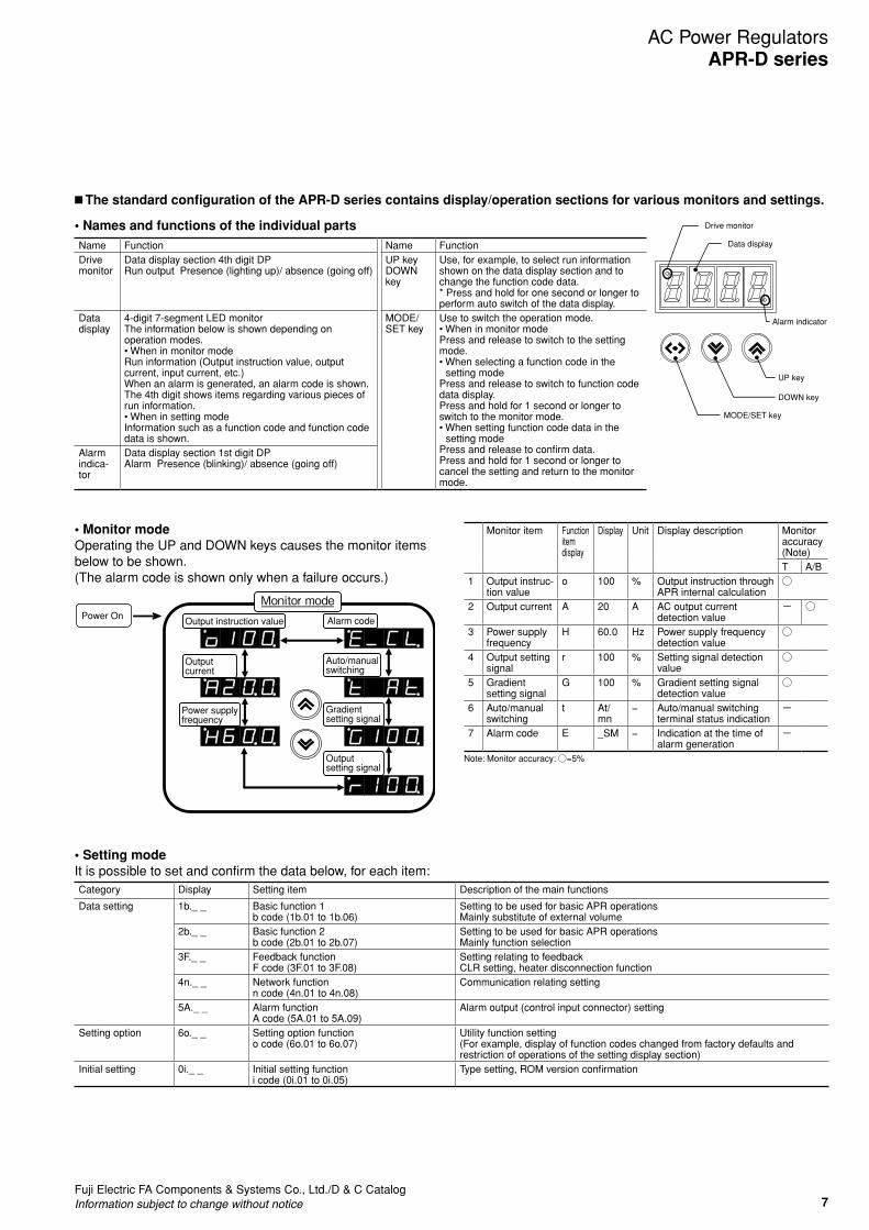
n ThestandardconfigurationoftheAPR-Dseriescontainsdisplay/operationsectionsforvariousmonitorsandsettings.
•NamesandfunctionsoftheindividualpartsName Function Name FunctionDrive monitor
Data display section 4th digit DPRun output Presence (lighting up)/ absence (going off)
UP keyDOWN key
Use, for example, to select run information shown on the data display section and to change the function code data. * Press and hold for one second or longer to perform auto switch of the data display.
Data display
4-digit 7-segment LED monitorThe information below is shown depending on operation modes.•WheninmonitormodeRun information (Output instruction value, output current, input current, etc.)When an alarm is generated, an alarm code is shown.The 4th digit shows items regarding various pieces of run information.•WheninsettingmodeInformation such as a function code and function code data is shown.
MODE/SET key
Use to switch the operation mode.•WheninmonitormodePress and release to switch to the setting mode.•Whenselectingafunctioncodeinthe
setting modePress and release to switch to function code data display.Press and hold for 1 second or longer to switch to the monitor mode.•Whensettingfunctioncodedatainthe
setting modePress and release to confirm data.Press and hold for 1 second or longer to cancel the setting and return to the monitor mode.
Alarm indica- tor
Data display section 1st digit DPAlarm Presence (blinking)/ absence (going off)
Drive monitor
Alarm indicator
Data display
UP key
DOWN key
MODE/SET key
•SettingmodeIt is possible to set and confirm the data below, for each item:Category Display Setting item Description of the main functions
Data setting 1b._ _ Basic function 1b code (1b.01 to 1b.06)
Setting to be used for basic APR operationsMainly substitute of external volume
2b._ _ Basic function 2b code (2b.01 to 2b.07)
Setting to be used for basic APR operationsMainly function selection
3F._ _ Feedback functionF code (3F.01 to 3F.08)
Setting relating to feedbackCLR setting, heater disconnection function
4n._ _ Network functionn code (4n.01 to 4n.08)
Communication relating setting
5A._ _ Alarm functionA code (5A.01 to 5A.09)
Alarm output (control input connector) setting
Setting option 6o._ _ Setting option functiono code (6o.01 to 6o.07)
Utility function setting(For example, display of function codes changed from factory defaults and restriction of operations of the setting display section)
Initial setting 0i._ _ Initial setting functioni code (0i.01 to 0i.05)
Type setting, ROM version confirmation
•MonitormodeOperating the UP and DOWN keys causes the monitor items below to be shown.(The alarm code is shown only when a failure occurs.)
Monitor item Function item display
Display Unit Display description Monitor accuracy (Note)T A/B
1 Output instruc- tion value
o 100 % Output instruction through APR internal calculation
○
2 Output current A 20 A AC output current detection value
− ○
3 Power supply frequency
H 60.0 Hz Power supply frequency detection value
○
4 Output setting signal
r 100 % Setting signal detection value
○
5 Gradient setting signal
G 100 % Gradient setting signal detection value
○
6 Auto/manual switching
t At/mn
− Auto/manual switching terminal status indication
−
7 Alarm code E _SM − Indication at the time of alarm generation
−
Note: Monitor accuracy: ○=5%
Output current
Output instruction value Alarm code
Output setting signal
Power supply frequency
Monitor modePower On
Auto/manual switching
Gradient setting signal

8Fuji Electric FA Components & Systems Co., Ltd./D & C Catalog
Information subject to change without notice
AC Power RegulatorsAPR-D series
•Heaterdisconnectiondetection(ControlmethodAtype,Btype)
Heaterdisconnectionisrecognizedwhentheloadcurrentbe-comes lower than the current value which has been set with the heater disconnection judgment level. - Applied heater: Alloy heater (Load which flows 40 to 100% of
the rated current when the output voltage is 100%)
- Number of parallel lines: 1 to 3 (The material and capacity must be identical.)
- For phase control/ phase angle proportion control When setting 5% or higher: Disconnection is detected when the
output current is 5 (approx.) to 100% of the rated current. - Cycle control When setting less than 5%: Invalid disconnection judgment When setting 5% or higher: Load open is detected when the
output current is less than 5% (approx.) of the rated current. - Judgment range: 30 to 100% of the output instruction value - Judgment accuracy: ±5%FS or less
Phase control/ phase angle proportion control Alloy heater
0
10
20
30
40
50
60
70
80
90
100
0 10 20 30 40 50 60 70 80 90 100Output voltage (%/V)
Heater disconnection detection characteristics through output voltage
100% 80% 60% 40% 20%Heater disconnection
judgment level:
Heater disconnection detection area
Out
put c
urre
nt (
%/A
)
•Gradientsetting/baseloadsetting
Characteristics Output adjustment range (%) Base load setting (%) Gradient setting (%)A 0 to 100 0 100B 0 to 80 0 80C 0 to 40 0 40D 0 to 100 0 200
Gradient setting: Set an output value to be presented when setting input is 100%. (Setting range: 0 to 200%)Note: The upper limit output value is 100% of input voltage.
Setting input
E F
G
0 25 50 75 100(%)
Setting input
0
20
40
60
80
100(%)
A
D
B
C
0
20
40
60
80
100(%)
0 25 50 75 100(%)
Out
put v
olta
ge (
RM
S v
alue
)
Out
put v
olta
ge (
RM
S v
alue
)
Characteristics Output adjustment range (%) Base load setting (%) Gradient setting (%)E 100 to 0 100 0F 50 to 100 50 100G 20 to 60 20 60
Base load: Set an output value to be presented when setting input is 0%. (Setting range: 0 to 100%) Actual output represents characteristics resulted from the connection between a base load setting value and gradient setting value using a straight line.
•ExampleofsettinggroupsFunction code Name Function code data (Settable range) Step size Unit Factory default1b.01 Manual digital setting 0 to 100.0(%) 0.1 % 01b.02 Gradient digital setting 0 to 200.0(%) 0.1 % 100.01b.03 Base load setting 0 to 100.0(%) 0.1 % 01b.04 Soft start time setting T type, A type: 0 to 100.0 (seconds)
B type: 0.5 to 100.0 (seconds)0.1 seconds 0.5
1b.05 Soft up time setting 0.1 seconds 0.51b.06 Soft down time setting 0.1 seconds 0.5
Setting input
E F
G
0 25 50 75 100(%)
Setting input
0
20
40
60
80
100(%)
A
D
B
C
0
20
40
60
80
100(%)
0 25 50 75 100(%)
Out
put v
olta
ge (
RM
S v
alue
)
Out
put v
olta
ge (
RM
S v
alue
)

9Fuji Electric FA Components & Systems Co., Ltd./D & C CatalogInformation subject to change without notice
AC Power RegulatorsAPR-D series
n Important notes for installation(1) Install in a dust-free place with high cooling effect. So that heat radia-
tion from APRs is possible, mount to a vertical metal object, confirm the vertical orientation shown in Figure 1, and ensure sufficient vertical and horizontal clearance among the units. If placing APRs closely one another, ensure sufficient clearance beyond the dimen-sions indicated in Figure 1 to reduce heat interference among the APRs.
(2)HeatgenerationofanAPRraisesthetemperatureinsidethepanel.Considering expected temperature rise, implement measures such as cooling and ventilation. (The upper limit of temperature inside the panel is 55°C.) The reference ambient temperature for the rated cur-rent is 40°C. When it exceeds 40°C, reduce the load current.
(3) Ensure a clearance with nearby objects, considering the work space of wiring tools at the individual terminals.
(4) The top of an APR has a partial opening. Be careful not to drop any object into the opening.
n Dimensions, mm
•Supplieditem(Ifspecifiedinorderinginformation)Setting device Type: RPD001 To be used for setting methods including variable resistor setting, 2-position control, and gradient setting.
Rating: 1 kΩJ, 2.5 W Type: RA30Y20SB102J (Manufacturer: TOKYO COSMOS)
Variable resistor
2.5±1 M9xP0.75
φ30
+2
−1
20max
R28max
1.5min
10±1
20±1
φ6-
0.10
30max
12±
0.2
φ3.
5
φ10
12
10
20
30
40 60
70
80
90
100
φ18
50
0
NPS-MX
44
Name label attachment
47
NameplateMounting hole processing drawing
Knob
φ26
φ6.
1
23
15
Name label sheet (Japanese/English, 8 kinds)
MANUAL SET.
GRADE SET.
HIGH SET.
LOW SET.
手動設定勾配設定HIGH設定LOW設定
0%
20%
40%
60%
80%
100%
120%
-10 0 10 20 30 40 50 60
周囲温度[℃]
許容
負荷
電流
Figure 1 Installation interval 図2 周囲温度-許容負荷電流特性
Note: The individual dimensions do not assume a work space is required for options (etc.).
100 mm or more2 mm or more
100 mm or more
100 mm or more
RPDE2020 type (20 A) RPDE2045, 2060 type (45 A, 60 A)
RPDE2100 type (100 A)
Upper part
2
35
Mass: 0.7 kg
120 13
35.8
8.5
160
6.5
175
175
Mounting dimension drawing
46.546.5
Control input power terminal M3
Control input connector
12.5
Communication connector
(Option)
(Option)
R6
R6.5
M5
M5
(Mounting hole to be used also for the earth terminal)
Main-circuitterminal M4
Main-circuit terminal M8
Upper part
2
72 44
Terminal cover
Terminal cover
Mass: 1.2 kg
162 13
21.5
8.5
165
6.5
180
180
Mounting dimension drawing60
60
Control input power terminal M3
Control input connector
34
Communication connector
(Option)
(Option)
R6
M5
M5
Main-circuit terminal M5
Upper part
3.5
88 33Terminal cover
Mass: 2.2 kg
167 13
23.7
8.5
180
6.5
195
195
Mounting dimension drawing111
88111
Control input power terminal M3
Control input connector
35
Communication connector
(Option)
(Option)
2-M6
2-M6

10Fuji Electric FA Components & Systems Co., Ltd./D & C Catalog
Information subject to change without notice
AC Power RegulatorsAPR-D series
n MEMO


Information in this catalog is subject to change without notice.
5-7, Nihonbashi Odemma-cho, Chuo-ku, Tokyo, 103-0011, Japan
URL http://www.fujielectric.co.jp/fcs/eng
Safety Considerations• Operate (keep) in the environment specified in the operating instructions and manual. High temperature, high humidity, condensation, dust,
corrosive gases, oil, organic solvents, excessive vibration or shock might cause electric shock, fire, erratic operation or failure.• For safe operation, before using the product read the instruction manual or user manual that comes with the product carefully or consult the
Fuji sales representative from which you purchased the product.• Products introduced in this catalog have not been designed or manufactured for such applications in a system or equipment that will affect
human bodies or lives.• Customers, who want to use the products introduced in this catalog for special systems or devices such as for atomic-energy control,
aerospace use, medical use, passenger vehicle, and traffic control, are requested to consult with Fuji Electric FA.• Customers are requested to prepare safety measures when they apply the products introduced in this catalog to such systems or facilities
that will affect human lives or cause severe damage to property if the products become faulty.• For safe operation, wiring should be conducted only by qualified engineers who have sufficient technical knowledge about electrical work or
wiring.• Follow the regulations of industrial wastes when the product is to be discarded.• For further questions, please contact your Fuji sales representative or Fuji Electric FA.
2015-07PDFFOLSHES170