simplifying mixed-signal verification - amazon s3...a hybrid approach. for example in a high-speed...
TRANSCRIPT

24
INTRODUCTION Mixed-signal design is the art of taking real world analog information, such as light, touch, sound, vibration, pressure, or temperature, and bringing it into the digital world for processing. The growth in mixed-signal design has been fueled by an increasing demand for AI, automotive, IoT, communication, and industrial hardware applications (Figure 1).
Designers are finding that these new markets for mixed-signal SoCs are revealing the shortcomings of legacy mixed-signal verification methodologies and tools. Some of these key issues are explored below.
THE “DIVIDE AND CONQUER” APPROACH IS RUNNING OUT OF STEAMThe push towards digitization & automation in real-world applications such as Industrial IoT and autonomous driving has exponentially increased the need for electronic components. These real-world use cases requires the need to translate physical signals to digital domain and vice versa to achieve functional correctness in real-time. Autonomous driving is one example where we have LIDARS & active sensors that capture the physical status of surroundings. These physical signals are analog in nature and are fed in to the ADAS system in the vehicle to make real-time decisions using extensive digital computing. This feedback loop is very critical for making autonomous driving possible. These practical real-world applications require the use of Mixed-Signal ICs with Analog & Digital components.
While designers must simulate the analog and digital subsystems together, the simulation algorithms are fundamentally different.
High precision circuits, in many cases, require very accurate SPICE simulation to ensure proper operation, while digital circuits can rely on HDL simulators that run much faster. As a result, the analog simulation will typically dominate the overall system simulation time, as Table 1 below explains.
Simplifying Mixed-Signal Verification
Figure 1: Mixed-Signal market segments
Digital Simulator Analog Simulator
Digital devices and circuits operate in a discrete domain, where the device pins and circuit nodes have a binary state of either HIGH (1), LOW (0), X (unknown), or Z at any given instant of time.
Analog devices and circuits operate in a continuous domain, where node voltages and branch currents can take arbitrary (positive or negative) values. They vary continuously, as a function of time.
The algorithm solves logical expressions sequentially by triggering events. Simulation is event-driven and discrete-domain based.
Applying Kirchhoff’s laws, the algorithm solves the entire analog system matrix at every time step.
There is a defined signal flow from input to output.
There is no defined signal flow in any direction and circuit elements can instantaneously influence any other element in the matrix.
Table 1: Digital solver versus analog solver

25
Accurate verification of these Mixed-Signal ICs has become even more stringent to satisfy real-world applications. Mixed-signal ICs needs to be verified thoroughly from System to individual blocks in a cohesive and accurate manner. There are several challenges to meet the mixed-signal verification requirements.
Bridging the methodology gap between Analog & Digital verification is of paramount importance to meet accuracy requirements and time-to-market needs. Mixed-signal verification ideally needs verification engineers with expertise in both analog and digital verification methodologies which is very difficult to achieve. Digital verification engineers are used to a more automated and top-down regression type verification methodologies.
This is in contrast to analog verification, which typically involves bottom-up methodology.
Figure 2: Mixed-Signal design and verification owners
Efficient mixed-signal verification methodologies needs a hybrid approach. For example in a high-speed IO design such as SerDes, the analog designers will need to verify the PLL jitter in the context of the top-level design. The top-level digital verification engineer will only need a functional PLL model to verify the system level requirements. An efficient mixed-signal platform should be flexible in terms of setup, ease-of-use, unified debugging environment and provide necessary abstraction of design data for SoC level & block-level verification requirements. Typical Mixed-Signal IC verification teams comprises of analog designers, digital designers, modeling experts to abstract analog circuit functions & system aggregators (Figure 2).
These 4 different function will need to work in cohesive manner to meet the verification requirements.

26
As a result, mixed-signal methodology has evolved continuously over the years to address these challenges. The two primary design methodologies are “analog driven” bottom-up and“digital driven” top-down.
ANALOG DRIVEN METHODOLOGYThe development of behavioral models (Figure 3) happens late in design cycle, when transistor-level simulations take too long to run. This begins to happen when designers integrate multiple SPICE blocks together. The amount of time and effort needed to create accurate models may push the project off schedule and model quality could be compromised.
After the model matures, it is easy to make minor tweaks to customize it for new specifications on the next version of the design. While turn-around time for project completion in an analog centric approach depends heavily on SPICE simulator performance, accurate modeling using Real Number Model (RNM) has recently seen good traction to expedite verification cycles.
Figure 3: Behavioral model validation using optimization
UNDERSTANDING MIXED-SIGNAL METHODOLOGIESMixed-signal design plays a critical role in ICs that have high-performance, low-noise analog interfaces connected to large digital signal processing blocks. This is the case in networking and wireless communication applications, where an analog/RF signal is converted to digital, processed, and converted back to analog. Mixed-signal design is now a key requirement for wearable, IoT, and automotive applications and the number of periphery sensors is growing in these applications. Sensors are proliferating to the periphery of individual blocks and they will eventually propagate to the periphery of the SoC itself. The various parts of the circuit must communicate more quickly in order to meet the increasing performance requirements for the overall system. In AI chips, for example, communication between processors and between memory and processors occurs at hundreds of gigabytes per second.
The combination of growing design size, dramatic changes in analog-digital integration and complexity, and the variability introduced at advanced process nodes threatens mixed-signal chip yield, performance, and longevity.

27
DIGITAL DRIVEN METHODOLOGYDigital verification techniques have been at the forefront in terms of new methodologies. Traditional analog verification still uses the bottom-up methodology and user generated test benches for functional and performance verification. A good engineering methodology uses hybrid approach which is a balance between top-down and bottom-up. In an organization, design groups can pick one approach over another based on their technical expertise, project schedule, and the scope of the project.
A good engineering methodology uses a “meet-in-the-middle” approach which is a balance between top-down and bottom-up. In an organization, design groups can pick one approach over another based on their technical expertise, project schedule, and the scope of the project.
MODERN MIXED-SIGNAL VERIFICATION CHALLENGESAs design complexity multiplies, verification complexity explodes. Verification is now the art of applying many unique methodologies for each class of sub-design within an IC.
In the pure digital verification space, the advent of new technologies, such as constrained-random data generation, assertion-based verification, coverage-driven verification, formal model checking, and intelligent testbench automation, have changed the way teams achieve functional verification productivity. However, most of these advances and new technologies have not been perfected for the analog domain and have not been extended to verify mixed-signal designs (Figure 4).
Mixed-signal verification is evolving at a slower pace and it faces some key challenges which are explored in the figure above.
PERFORMANCEIn mixed-signal simulations, the analog domain requires analog solvers and digital domain requires digital solvers. Inherently, digital solvers are event based and are exponentially faster than analog solvers that require very small timesteps. In order to overcome the analog simulation bottleneck, analog circuity with transistors are replaced by behavior models based on real number models. However, behavior models cannot meet the high accuracy needed in today’s mixed-signal designs. Therefore, the need for high performance analog simulator is essential as well.
Figure 4: Digital versus analog/mixed-signal verification technology progression

28
Figure 5: Mixed-Signal bugs
COMPLEX USE MODELTraditional mixed-signal simulators available in the market today evolved more as an after-thought to combine analog and digital verification needs. There was little thought given to provide a simple use model. Most of the solutions available now have very complex set-up and do not provide a seamless interface to move between the digital centric flow and analog centric flow. Ideal mixed-signal solution should have a unified interface that is intuitive for analog and digital verification engineers.
MIXED-SIGNAL DEBUGIn mixed-signal design, errors most often occur at the interfaces between analog and digital blocks. Frequently, bugs in the interfaces are identifiable only at a higher level of hierarchy, sometimes at the I/O pins (Figure 5).
Mixed-signal debug gets even more complicated when the design employs advanced, low-power techniques. For example, data corruption in a digital block due to faulty power sequencing can pass to an analog block, resulting in erroneous voltage conversion. Scenarios like this are difficult to debug by analog designers who are unaware of digital low-power techniques.
Teams face a key question: how much time should the team invest in creating models and is the return on investment worth the resources and time spent? For complex analog designs at smaller technology nodes, design teams still prefer to use a SPICE simulator which guarantees accuracy. This puts immense pressure on the EDA tool provider to offer a solution that can satisfy both performance and accuracy requirements that design teams demand.
MULTIPLE ENGINE AND DESIGN ENVIRONMENTThere is no single methodology for verifying a SoC. Teams employ multiple simulation engines in different contexts through varying verification flows. The design verification methodology changes from low-level design up to the system level. Migrating designs between engines can take months and a tremendous amount of effort. Additionally, the cost of migrating a SoC verification flow grows exponentially with design size.
Digital and analog teams working on a common SoC engage in multiple activities that involve different tools without any means of effective communication between them. It gets challenging when the time comes to integrate the IC for full mixed-signal verification because no designer has complete insight into the use models and configurations of all the tools in the flow. What is needed is a platform that can easily fit into any design environment and verification methodology for efficient verification closure.

29
INTRODUCING SYMPHONYThe next-generation Symphony Mixed-Signal Platform provides designers with unprecedented flexibility for choosing their own design methodology: bottom-up, top-down, or any combination of the two. Designers can make intelligent trade-offs by choosing detailed, continuous analog models or SPICE for high accuracy and discrete behavioral models for simulation speed performance.
Symphony Mixed-Signal Platform is the industry’s fastest and most configurable mixed-signal solution to accurately verify design functionality, connectivity, and performance across analog/digital (A/D) inter-faces at all levels of the design hierarchy for all IC applications (Figure 6).
ACCURACY AND SPEED ADVANTAGESymphony’s modular architecture leverages Mentor’s Analog FastSPICE (AFS) circuit simulator to provide fast mixed- signal simulation performance with
nanometer (nm) SPICE accuracy and capacity of 20M SPICE elements. With certified accuracy by the world’s leading foundries, AFS delivers 5–10x faster performance than traditional SPICE and 2–6x faster performance than parallel SPICE simulators. Symphony has been proven on a wide range of ICs and IC subsystems including ADCs, transceivers, PMICs, multi-GHz PLLs/DLLs, and sensors (Figure 7).
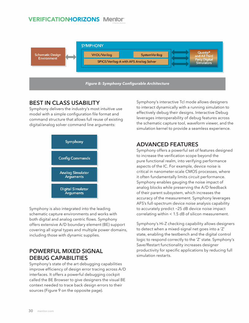
FULLY CONFIGURABLE ARCHITECTURESymphony’s unique, fully configurable fit-to-purpose architecture (Figure 8 on the following page) and design-aware technologies provide verification teams with the ability to integrate and optimize their mixed-signal flow for any application. Symphony works with all leading digital solvers, including Mentor’s Questa®, allowing designers to maximize reuse of their existing verification infrastructure including testbenches, stimuli, scripts, post processing, encrypted IP blocks, and A/D netlists.Figure 6: Symphony Mixed-Signal Platform
Figure 7: Analog FastSPICE performance chart
30
BEST IN CLASS USABILITYSymphony delivers the industry’s most intuitive use model with a simple configuration file format and command structure that allows full reuse of existing digital/analog solver command line arguments:
Symphony is also integrated into the leading schematic capture environments and works with both digital and analog centric flows. Symphony offers extensive A/D boundary element (BE) support covering all signal types and multiple power domains, including those with dynamic supplies.
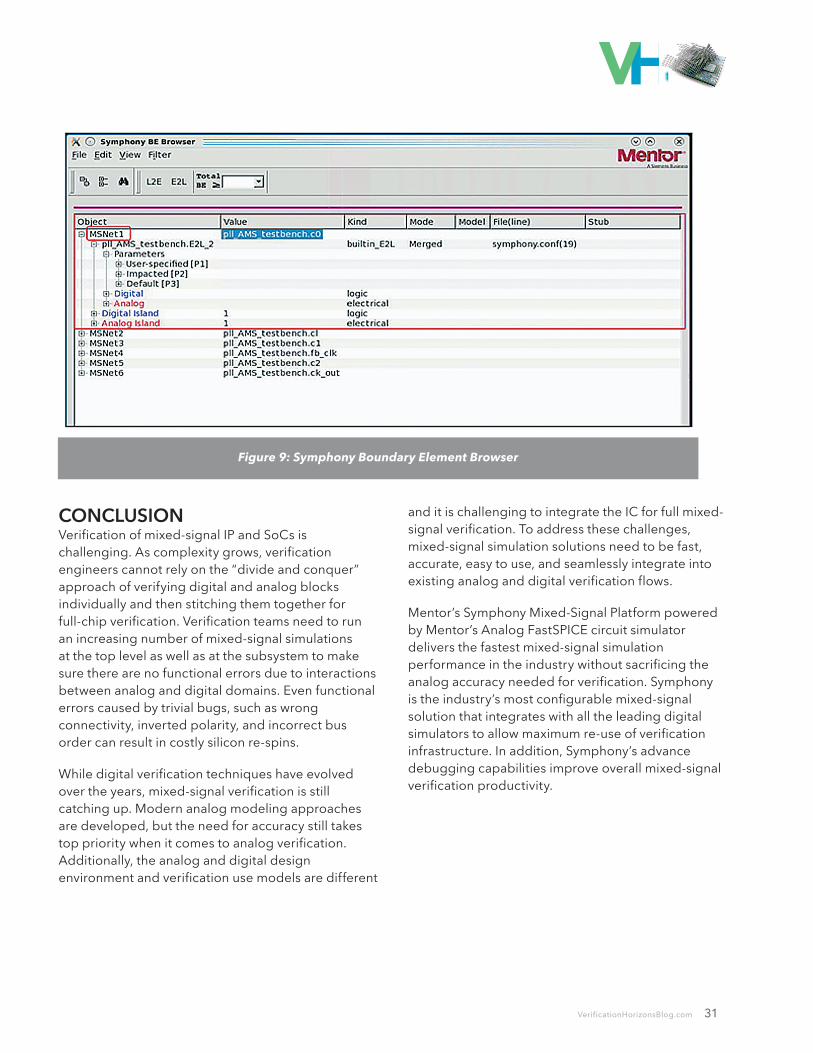
POWERFUL MIXED SIGNAL DEBUG CAPABILITIESSymphony’s state of the art debugging capabilities improve efficiency of design error tracing across A/D interfaces. It offers a powerful debugging cockpit called the BE Browser to give designers the visual BE context needed to trace back design errors to their sources (Figure 9 on the opposite page).
Symphony’s interactive Tcl mode allows designers to interact dynamically with a running simulation to effectively debug their designs. Interactive Debug leverages interoperability of debug features across the schematic capture tool, waveform viewer, and the simulation kernel to provide a seamless experience.
ADVANCED FEATURESSymphony offers a powerful set of features designed to increase the verification scope beyond the pure functional realm, into verifying performance aspects of the IC. For example, device noise is critical in nanometer-scale CMOS processes, where it often fundamentally limits circuit performance. Symphony enables gauging the noise impact of analog blocks while preserving the A/D feedback of their parent subsystem, which increases the accuracy of the measurement. Symphony leverages AFS’s full-spectrum device noise analysis capability to accurately predict ~25 dB device noise impact correlating within < 1.5 dB of silicon measurement.
Symphony’s Hi-Z checking capability allows designers to detect when a mixed-signal net goes into a ‘Z’ state, enabling the testbench and the digital control logic to respond correctly to the ‘Z’ state. Symphony’s Save/Restart functionality increases designer productivity for specific applications by reducing full simulation restarts.
Figure 8: Symphony Configurable Architecture
31
CONCLUSIONVerification of mixed-signal IP and SoCs is challenging. As complexity grows, verification engineers cannot rely on the “divide and conquer” approach of verifying digital and analog blocks individually and then stitching them together for full-chip verification. Verification teams need to run an increasing number of mixed-signal simulations at the top level as well as at the subsystem to make sure there are no functional errors due to interactions between analog and digital domains. Even functional errors caused by trivial bugs, such as wrong connectivity, inverted polarity, and incorrect bus order can result in costly silicon re-spins.
While digital verification techniques have evolved over the years, mixed-signal verification is still catching up. Modern analog modeling approaches are developed, but the need for accuracy still takes top priority when it comes to analog verification. Additionally, the analog and digital design environment and verification use models are different
and it is challenging to integrate the IC for full mixed-signal verification. To address these challenges, mixed-signal simulation solutions need to be fast, accurate, easy to use, and seamlessly integrate into existing analog and digital verification flows.
Mentor’s Symphony Mixed-Signal Platform powered by Mentor’s Analog FastSPICE circuit simulator delivers the fastest mixed-signal simulation performance in the industry without sacrificing the analog accuracy needed for verification. Symphony is the industry’s most configurable mixed-signal solution that integrates with all the leading digital simulators to allow maximum re-use of verification infrastructure. In addition, Symphony’s advance debugging capabilities improve overall mixed-signal verification productivity.
Figure 9: Symphony Boundary Element Browser

VERIFICATION ACADEMY
The Most Comprehensive Resource for Verification Training
33 Video Courses Available Covering
• DO-254• UVM Framework• UVM Debug• Portable Stimulus Basics• SystemVerilog OOP• Formal Verification• Metrics in SoC Verification• Verification Planning• Introductory, Basic, and Advanced UVM• Assertion-Based Verification• FPGA Verification• Testbench Acceleration• PowerAware Verification• Analog Mixed-Signal Verification
UVM and Coverage Online Methodology Cookbooks
Discussion Forum with more than 10,000 questions asked
Verification Patterns Library www.verificationacademy.com

Editor: Tom Fitzpatrick
Program Manager: Rebecca Granquist
Mentor, A Siemens Business Worldwide Headquarters
8005 SW Boeckman Rd. Wilsonville, OR 97070-7777
Phone: 503-685-7000
To subscribe visit: www.mentor.com/horizons
To view our blog visit: VERIFICATIONHORIZONSBLOG.COM
Verification Horizons is a publication of Mentor, A Siemens Business
©2018, All rights reserved.