similarity - جامعة بابل | university of babylon similarity exists between two systems when,...
TRANSCRIPT

Substituting these dimensionless numbers into Equation 8-12 yields,
N K N NDD
WD
HDp
bFr
d T
A
f
A
g
A
h
=
− −Re (8-13)
SIMILARITY
Equality of all groups in Equation 8-13 assures similarity betweensystems of different sizes. The types of similarity are geometric,kinematic, and dynamic. The last three terms of Equation 8-13 representthe conditions for geometric similarity, which require that all cor-responding dimensions in systems of different sizes have the sameratio to each other. For geometric similarity, Equation 8-13 becomes
N K N NPb
Frd= − −
Re (8-14)
The constant K and the exponents b and d must be determined forthe particular type of agitator, its size and location in the tank, thedimensions of the tank, and the depth of the liquid.
Kinematic similarity exists between two systems of different sizeswhen they are geometrically similar and when the ratios of velocitiesbetween corresponding points in one system are equal to those in the other.
Dynamic similarity exists between two systems when, in additionto being geometrically and kinematically similar, the ratios of forcesbetween corresponding points in one system are equal to those in the other.
The value of NRe determines whether the flow is laminar or turbulentand is a significant group affecting the power consumption. TheFroude number NFr, representing the ratio of inertial to gravitationalforces, is only significant when the liquid in the tank swirls to suchan extent that a deep vortex is formed and the wave or surface effectsbecome important. In an unbaffled vessel, a balance between theinertial and gravitational forces determines the shape of any vortex.The Power number NP may be considered as a drag coefficient orfriction factor.
Experimental data on power consumption are generally plotted asa function of the Power number NP versus Reynolds number NRe, thatis by rearranging Equation 8-14.
mixing of fluids
18

Φ = =−−N
NK NP
Frd
bRe (8-15)
For a fully baffled tank, b = 0 and Φ = NP. A generalized plot ofEquation 9-15 is shown in Figure 8-11. The power correlation indicatesthree ranges of liquid motion: laminar (viscous), transition, and tur-bulent. The laminar or viscous range occurs below a Reynolds numberof 10. The expected result of the Power number being inverselyproportional to the Reynolds number is also confirmed by experimentaldata. The Froude effects are unimportant and a logarithmic plot of therelation between Power number and Reynolds number gives a slopeof –1 in this range. Fully turbulent agitation occurs above a Reynoldsnumber of 10,000. The range between these limits can be describedas the transition flow because flow patterns change depending onthe Reynolds number. Figure 8-12 shows the Power number versusReynolds number plot for the unbaffled system. Both Figures 8-11 and8-12 are identical to point C where NRe ≅ 300. As the Reynolds
Figure 8-11. Power curve for the standard tank configuration. (Source:Holland, F. A. and Bragg, R. Fluid Flow for Chemical Engineers, 2nd ed.,Edward Arnold, 1995.)
mixing of fluids
19

Figure 8-12. Power curve for the standard tank configuration without baffles.(Source: Holland, F. A. and Bragg, R. Fluid Flow for Chemical Engineers,2nd ed., Edward Arnold, 1995.)
number for mixing increases beyond point C in the unbaffled system,vortexing increases and the Power number falls sharply. Figure 8-13shows the Power number as a function of the Reynolds number forshear thinning fluids. The full line gives the Newtonian Power numberobtained by Rushton et al. [10] for a flat-blade turbine system, whilethe dashed line shows Metzner and Otto’s [11] plot for shear thinningliquids. Figure 8-13 illustrates that at no point is the shear thinningpower curve higher than the Newtonian power curve. Therefore, theuse of the Newtonian power curve to determine the power will givea conservative value when used for shear thinning liquids. Figure 8-14shows Power number correlations for various types of agitators. In thefully turbulent flow, the curve becomes horizontal and the Powernumber NP is independent of the Reynolds number.
Rushton et al. [10] performed extensive measurements of the powerrequirements for geometrically similar systems and found that forbaffled tanks, the Froude number plays no part in determining thepower requirements, as vortices do not form in such systems. Forunbaffled systems, the Froude number plays a part above NRe of about
mixing of fluids
20

300. They reported NP = 6.3 in the turbulent range of 10,000. Afterextensive curve fitting of their experimental data, a single curve wasobtained for any particular unbaffled configuration. If Φ is plotted asa function of NRe where Φ is defined as
Φ = NP for NRe < 300
Φ =−( )[ ]
N
N
P
Fra N blog Re
for NRe > 300 (8-16)
where a and b are constants for any configuration (Figure 8-14).Dickey and Fenic [12] observed that the impeller characteristics havesignificant influence on the Power number correlation.
Figure 8-13. Deviation from Newtonian power curve for shear thinning liquids.(Source: Holland, F. A. and Bragg, R. Fluid Flow for Chemical Engineers,2nd ed., Edward Arnold, 1995.)
mixing of fluids
21

Figure 8-14. Power number versus Reynolds number correlation for commonimpellers. (Source: Ruchton et al., Chem. Eng. Prog., 46, No. 8, 495, 1950.Reprinted with permission of AIChE. Copyright © 1950. All rights reserved.)
Two characteristics of Figure 8-14 are:
1. At low NRe < 1.0, NP ∝ 1/NRe, independent of the presenceof baffles.
2. At high Reynolds, at which most mixing operations are per-formed, the Power number is constant, that is, NP ∝ P/ρN3D5
A= constant.
Rushton et al. [10] investigated the effect of varying the tankgeometrical ratios and the correlation of the Power number withReynolds number. At high Reynolds number, it was inferred that,
mixing of fluids
22

Fluid Mixing in Reactors 575
• Φ is relatively unchanged when DT/DA is varied from 2 to 7 forturbine- and propeller-agitated baffled systems.
• Φ is unchanged when H/DA is varied from 2 to 4.• Φ is unaltered when E/DA is changed from 0.7 to 1.6.• Φ changes to Φ ∝ (J/DA)0.3 when J/DT is changed from 0.05
to 0.17.• Φ depends on the number of blades in the turbine impeller as:
Φ ∝ (B/6)0.8 if B < 6 and Φ ∝ (B/6)0.7 if B > 6 (where B = numberof impeller blades).
• If off-centered and inclined propellers without baffles or side-entering propellers without baffles are used, no vortex forms andthe Φ versus NRe curve for the corresponding baffled tank canbe used to estimate the power requirements.
These conclusions are speculative and experimental curves mustbe generated if more than one geometrical ratio differs from thestandard value.
The power consumed by an agitator at various rotational speeds andphysical properties (e.g., viscosity and density) for a system’s geo-metry can be determined from the Power number correlation. Theprocedure involves:
• Calculating the Reynolds number NRe for mixing.• Reading the Power number NP from the appropriate curve, and
calculating the power P given by
P N N DP A= • ρ 3 5 (8-17)
or P N D NA Fra N b= −( )[ ]Φρ 3 5 •
log Re (8-18)
Equations 8-17 and 8-18 are the power consumed by the agitator.Additional power is required to overcome electrical and mechanicallosses. A contingency of motor loading as a percentage (e.g., 85%) isadded when selecting the motor. Equation 8-17 can also be rearrangedto determine impeller diameter when it is desired to load an agitatorimpeller to a given power level. The torque delivered to the fluid byan impeller from its speed and power draw is determined by:
τπ
ρπ
= = −PN
N N DN mP A
2 2
2 5
(8-19)
mixing of fluids
23

The primary pumping capacity of an impeller is determined by theimpeller diameter, the Pumping number, and the rotational speed. ThePumping number NQ is defined by [13]
NQ
NDQP
A
= 3 (8-20)
The Pumping number is used to determine the pumping rate QP ofan impeller,
where QP = effective pumping capacity, m3/secN = impeller rotational speed, sec–1
DA = impeller diameter, m
Hicks et al. [8] developed a correlation involving the Pumpingnumber and impeller Reynolds number for several ratios of impellerdiameter to tank diameter (DA/DT) for pitched-blade turbines. Fromthis correlation, QP can be determined, and thus the bulk fluid velocityfrom the cross-sectional area of the tank. The procedure for deter-mining the parameters is iterative because the impeller diameter DAand rotational speed N appear in both dimensionless parameters (i.e.,NRe and NQ).
Figure 8-15 shows plots of Pumping number NQ and Power numberNP as functions of Reynolds number NRe for a pitched-blade turbineand high-efficiency impeller. Hicks et al. [8] further introduced thescale of agitation, SA, as a measure for determining agitation intensityin pitched-blade impellers. The scale of agitation is based on a char-acteristic velocity, v, defined by
vQA
P
V
= (8-21)
where v = characteristic velocity, m/secAV = cross-sectional area of the tank, m2
The characteristic velocity can be expressed as:
v N N DDDQ A
A
T
∝
2
2 (8-22)
mixing of fluids
24
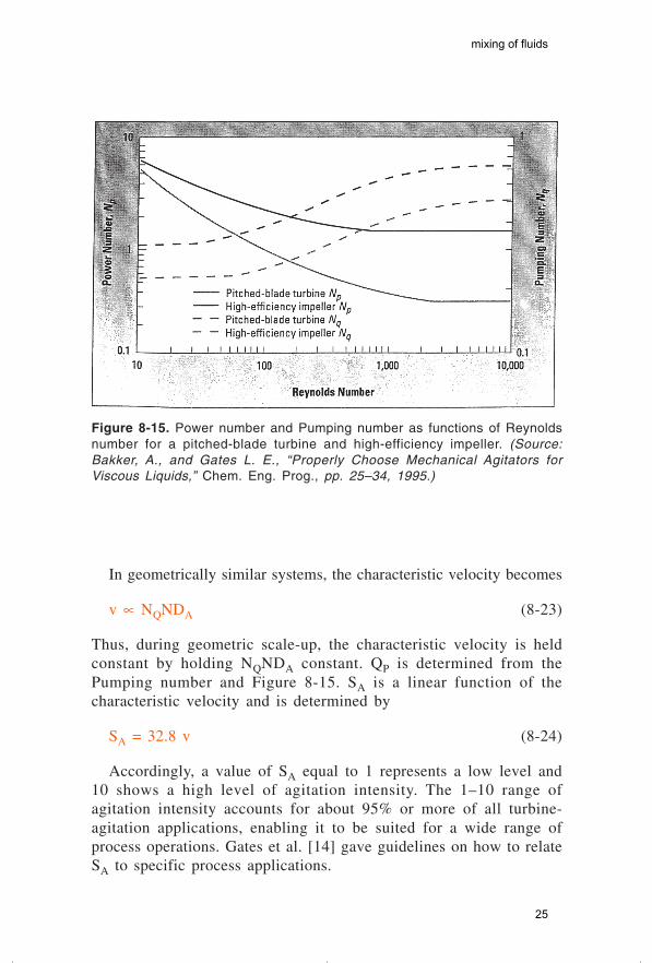
Figure 8-15. Power number and Pumping number as functions of Reynoldsnumber for a pitched-blade turbine and high-efficiency impeller. (Source:Bakker, A., and Gates L. E., “Properly Choose Mechanical Agitators forViscous Liquids,” Chem. Eng. Prog., pp. 25–34, 1995.)
In geometrically similar systems, the characteristic velocity becomes
v ∝ NQNDA (8-23)
Thus, during geometric scale-up, the characteristic velocity is heldconstant by holding NQNDA constant. QP is determined from thePumping number and Figure 8-15. SA is a linear function of thecharacteristic velocity and is determined by
SA = 32.8 v (8-24)
Accordingly, a value of SA equal to 1 represents a low level and10 shows a high level of agitation intensity. The 1–10 range ofagitation intensity accounts for about 95% or more of all turbine-agitation applications, enabling it to be suited for a wide range ofprocess operations. Gates et al. [14] gave guidelines on how to relateSA to specific process applications.
mixing of fluids
25

MIXING TIME CORRELATION
A distinction was made earlier between mixing and agitation. Thethird term in liquid mixing is blending. This refers to the interminglingof miscible fluids to produce some degree of uniformity. A criterionfor good mixing may only be visual. For example, it could be aparticular color from two different color liquids, or the color changeof an acid-base indicator that determines the liquid blending times.Characterization of blending in agitated vessels is usually in terms ofmixing time. This is the time required to achieve some specifieddegree of uniformity after introduction of a tracer. Table 8-5 givesvarious techniques for determining blending time.
Each technique measures a different degree of uniformity, therefore,the time required for blending may differ from one method to theother. The correlation of blending time as derived from dimensionalanalysis is applicable to all techniques. Uhl and Gray [6] summarizedmany of the experiments and correlations on blending and mixingtimes. For a given tank and impeller or geometrically similar systems,the mixing time is predicted to vary inversely with the stirrer speed,as confirmed in various studies [15,16,17,18]. Figure 8-16 shows plotsof mixing time (tN) against the Reynolds number NRe for severalsystems. As an example, a turbine with DA/DT = 1/3 and DT/H = 1,the value of Nt is 36, for NRe > 103, compared with a predicted valueof 38.
Table 8-5Methods for determining blending time
Technique Tracer Blend time reached when
Grab sample Any material that can Samples do not vary more thanbe analyzed. ±X% from final concentration.
Dye introduction Dyed fluid. Uniform color is attained.
Conductivity cell Concentration of salt Measured conductivity that repre-solution. sents concentration is within
±X% of final concentration.
Acid-base indicator Acid (or base). Neutralization is complete asdetermined by color changeof indicator.
Source: Dickey, D. S., “Dimensional analysis for fluid agitation system,” Chem. Eng.,January 5, 1976.
mixing of fluids
26

Figure 8-16. Mixing times in agitated vessels. Dashed lines representunbaffled tanks; solid lines represents a baffled tank. (Source: McCabe,W. L., et al., Unit Operations of Chemical Engineering, 4th ed., McGraw-HillBook Company, New York, 1985.)
Prochazka and Landau [19] developed a mixing time correlation fora single Rushton turbine impeller in a baffled tank in the standardconfiguration for NRe > 104:
NtDD
XX
T
A
o
c
=
0 9052 57
. log.
(8-25)
For a propeller, the mixing time is given by:
NtDD
XX
T
A
o
c
=
3 482 05
. log.
(8-26)
For a pitched-blade turbine, the mixing time is:
NtDD
XX
T
A
o
c
=
2 022 20
. log.
(9-27)
mixing of fluids
27

where Xo = initial value of the degree of inhomogeneity, which variesbetween 1 and 3; a value of 2 is recommended
Xc = final integral mean value of the local degree of inhomo-geneity and is defined as:
XC t C
C Ccx
x i
= ( ) −−
(8-28)
where C(t) = instantaneous concentrationCi = initial concentrationCx = final concentration
Xc = 0.05 for most configurations. Moo-Young et al. [20] correlatedtheir mixing results from
Nt KNa= Re (8-29)
where K = 36 and a = 0 for turbines in baffled tanks for 1,000 < NRe< 105. Sano and Usui [21] developed an expression for mixing timesby tracer injection for turbines as:
NtDD
WD
nA
T TP=
− −−3 8
1 80 0 510 47.
. .. (8-30)
where nP is the number of blades. Gray [22] found the mixing timesof helical ribbon impellers to be of the form
Nt = 30 (8-31)
where N is the rotational speed of the helical ribbon impeller, and t isthe batch mixing time. Fasano et al. [23] expressed the blend time forturbulence conditions in a standard baffled tank (i.e., NRe > 10,000) as:
t
a NDD
DH
A
T
bT
99 0 5
4 065=
..
(8-32)
mixing of fluids
28
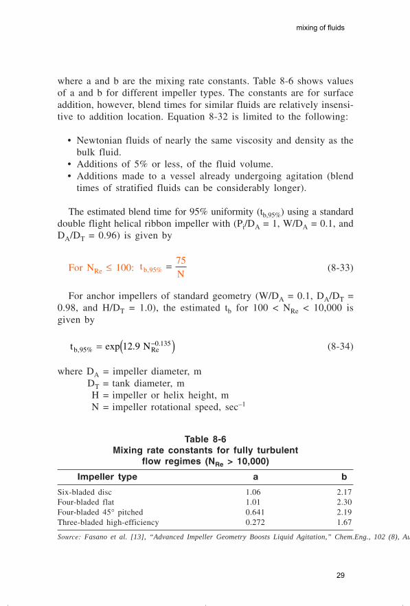
where a and b are the mixing rate constants. Table 8-6 shows valuesof a and b for different impeller types. The constants are for surfaceaddition, however, blend times for similar fluids are relatively insensi-tive to addition location. Equation 8-32 is limited to the following:
• Newtonian fluids of nearly the same viscosity and density as thebulk fluid.
• Additions of 5% or less, of the fluid volume.• Additions made to a vessel already undergoing agitation (blend
times of stratified fluids can be considerably longer).
The estimated blend time for 95% uniformity (tb,95%) using a standarddouble flight helical ribbon impeller with (Pi/DA = 1, W/DA = 0.1, andDA/DT = 0.96) is given by
For NRe ≤ 100: tNb, %9575= (8-33)
For anchor impellers of standard geometry (W/DA = 0.1, DA/DT =0.98, and H/DT = 1.0), the estimated tb for 100 < NRe < 10,000 isgiven by
t Nb, % Re.exp .95
0 13512 9= ( )− (8-34)
where DA = impeller diameter, mDT = tank diameter, mH = impeller or helix height, mN = impeller rotational speed, sec–1
Table 8-6Mixing rate constants for fully turbulent
flow regimes (NRe > 10,000)
Impeller type a b
Six-bladed disc 1.06 2.17Four-bladed flat 1.01 2.30Four-bladed 45° pitched 0.641 2.19Three-bladed high-efficiency 0.272 1.67
Source: Fasano et al. [13], “Advanced Impeller Geometry Boosts Liquid Agitation,” Chem.Eng., 102 (8), August 1994.
mixing of fluids
29

Pi = pitch of a helical ribbon impeller, mW = blade width, m
Bakker and Gates [23] compared both Equations 8-33 and 8-34 andinferred that at a Reynolds number of 100, it will take an anchorimpeller more than 13 times as long to achieve 95% uniformity as ahelical ribbon impeller operating at the same speed. These impellersrequire cooling to remove the excess heat due to their high powerinput. The mixing time that was considered relates to tanks operatingin closed systems (e.g., batch reactors). In a continuous feed tank, themixing time is generally shorter than in a closed tank.
Example 8-1
Calculate the power for agitation of a liquid of density 950 kg/m3
and viscosity 250 cP given the following configuration: number ofblades B = 6, agitator diameter 0.61 m, and speed at 90 rpm. Othergeometrical ratios are shown in Figure 7-1. A disc-mounted flat turbineis used.
Solution
The Reynolds number for mixing is
NNDA
Re = ρµ
2
N = the number of revolutions per sec is (90/60) = 1.5 rev/sec.
Nkgm
mkg
m
Re
. .•
sec•
• sec
=( )( )( )
×
−
950 1 5 0 61
250 101
2
3 3
2
NRe = 2,121
Using curve 6 in Figure 8-14, the Power number is NP = 5.0. Thetheoretical power for mixing is
mixing of fluids
30

P N N Dkgm
revmP A= = × × ×
ρ 3 5 3 53
3
355 0 950 1 5 0 61. . . •
sec•
= 1,353.99 W
= 1.35 kW (1.82 hp)
(NB: 1 kW = 1.341 hp)
Example 8-2
Calculate the theoretical power for a six-blade, flat-blade turbinewithout baffles, but with the standard tank configuration shown inTable 8-2. Use the same data as in Example 8-1.
Solution
Since the tank is unbaffled, the Froude number is a factor and itseffect is calculated from
NN D
grev m
mFrA= =
( )( )
2 2
2
2
1 5 0 61
9 81
. .
. sec•
sec
= 0.14
NRe ,= 2 121
The constants a and b for an unbaffled tank R = 0, are a = 1.0 andb = 40. Using curve 5 in Figure 8-14, the Power number is NP = 2.0
N ma N
bFrm
log Rewhere = − 10
mixing of fluids
31

m = − = −1 0 2 12140
0 058210. log ,.
NFrm = =−0 14 1 12120 0582. ..
Therefore, power P N N D NP A Frm= ρ 3 5
= 2 0 950 1 5 0 61 1 12123 53
3
35. . . . •
sec•× × × ×
kgm
revm
= 607.24 W
= 0.61 kW (0.81 hp)Studies on various turbine agitators have shown that geometric
ratios that vary from the standard design can cause different effectson the Power number NP in the turbulent regions [24].
• For the flat, six-blade open turbine, NP ∝ (W/DA)1.0.• For the flat, six-blade open turbine, varying DA/DT from 0.25 to
0.5 has no effect on NP.• When two six-blade open turbines are installed on the same shaft
and the spacing between the two impellers (vertical distancebetween the bottom edges of the two turbines) is at least equalto DA, the total power is 1.9 times a single flat-blade impeller.For two six-blade pitched-blade (45°) turbines, the power is about1.9 times that of a single pitched-blade impeller.
• A baffled, vertical square tank or a horizontal cylindrical tank hasthe same Power number as a vertical cylindrical tank.
SCALE-UP OF MIXING SYSTEMS
The calculation of power requirements for agitation is only a partof the mixer design. In any mixing problem, there are several definedobjectives such as the time required for blending two immiscibleliquids, rates of heat transfer from a heated jacket per unit volume ofthe agitated liquid, and mass transfer rate from gas bubbles dispersedby agitation in a liquid. For all these objectives, the process resultsare to achieve the optimum mixing and uniform blending.
mixing of fluids
32