sign support inspection guidelines
TRANSCRIPT

SIGN SUPPORT
INSPECTION
GUIDELINES
Ministry of TransportationBridge OfficeMay 8, 2002
May 8, 2002 Sign Support Inspection Guidelines Pg. 1
TABLE OF CONTENTS
I. LIST OF FIGURES
II. OVERVIEW OF GUIDELINESA. IntroductionB. InventoryC. InspectionD. Maintenance and RepairE. Condition of Sign Support Structure
III. INVENTORY, HISTORICAL AND ELEMENT DATA REQUIREMENTSA. Inventory DataB. Historical DataC. Element Data
IV. INSPECTION OVERVIEW
V. INSPECTION DETAILSA. Field Inspection InformationB. Element InformationC. Additional InvestigationsD. Inspection – Element Details
1. Foundations2. Connections3. Chord/Main Members4. Diagonals5. Attachments6. Coatings
VI. MAINTENANCE AND REPAIR
VII. STRUCTURE RATING
VIII. REFERENCES
APPENDIX A: Maintenance ProceduresAPPENDIX B: Repair ProceduresAPPENDIX C: Inspection Form (Inventory)APPENDIX D: Inspection Form (Inspection and Element)APPENDIX E: 1999 Bridge Office Memo for Aluminum Tapered Leg Sign SupportsAPPENDIX F: Photographs

May 8, 2002 Sign Support Inspection Guidelines Pg. 2
I. LIST OF PHOTOGRAPHS
The photographs listed below are located in Appendix F.
0.1 Aluminum Tapered Leg (ATL) Sign Support0.2 Aluminum Circular Leg (ACL) Sign Support0.3 Aluminum Rectangular Leg (ARL) Sign Support0.4 Changeable Message Sign Support (CMS)0.5 Tri-Chord (TC) Sign Support0.6 Cantilever (C) Sign Support0.7 Mono Tube (MT) Sign Support0.8 Bridge Mounted Sign Support (BM2), connected to fascia0.9 Bridge Mounted Sign Support (BM2), connected to fascia and soffit0.10 Bridge Mounted Sign Support (BM2), connected to fascia0.11 Bridge Mounted Sign Support (BM3), connected to fascia and soffit0.12 Bridge Mounted Sign Support (BM3), connected to fascia and soffit0.13 Bridge Mounted Sign Support (BM2S), connected to fascia and soffit1a.1 Foundation - Concrete, Projection of Foundation above ground1a.2 Foundation - Concrete, on Barrier Wall1a.3 Foundation - Concrete, Bridge Mounted for ATL Type Sign Support1b.1 Foundation - Steel Pedestal Under ATL Type Sign Support1c.1 Foundation - Bearing Surface, Leg on Concrete1c.2 Foundation - Bearing Surface, Leg with Grout under Base Plate1c.3 Foundation - Bearing Surface, Leg with Rubber Pad under Base Plate2a.1 Chords - Base Plate, Aluminum Casting of ATL Type Sign Support2b.1 Chords - Leg, ATL Type Sign Support2b.2 Chords - Leg, ACL Type Sign Support2b.3 Chords - Leg, ARL Type Sign Support2b.4 Main Member - Leg, Single Column Leg of Sign Support2c.1 Chords - Corner Arc, ATL Type Sign Support2d.1 Chords - Horizontal, ATL Type Sign Support2d.2 Chords - Horizontal, CMS Type Sign Support2d.3 Chords - Horizontal, Tri-Chord Sign Support2d.4 Chords - Horizontal, Cantilever Sign Support3a.1 Diagonals - Leg, ATL Type Sign Support3a.2 Diagonals - Leg, ACL Type Sign Support3b.1 Diagonals - Corner Arc, ATL Type Sign Support3c.1 Diagonals - Truss, ATL Type Sign Support3c.2 Diagonals - Truss, CMS Type Sign Support4a.1 Connection - Base, Aluminum Base Plate of ARL Type Sign Support4a.2 Connection - Base, Steel Base Plate of Single Column Leg4a.3 Connection - Base, Anchor Bolts at Attachment Of Bridge Mounted Sign Support to Fascia4b.1 Connection - Leg, ACL Type Sign Support4b.2 Connection - Leg, ARL Type Sign Support4b.3 Connection - Leg, Changeable Message Sign4b.4 Connection - Leg, Tri-Chord Sign Support4b.5 Connection - Leg, Cantilever Sign Support4b.6 Connection - Leg, Mono-Tube Sign Support4c.1 Connection - In Line Chord, ATL Type Sign Support4c.2 Connection - In Line Chord, ATL Type Sign Support (Alternate)4c.3 Connection - In Line Chord, CMS Type Sign Support4c.4 Connection - In Line Chord, Tri-Chord Sign Support

May 8, 2002 Sign Support Inspection Guidelines Pg. 3
4c.5 Connection - In Line Chord, Mono-Tube Sign Support4d.1 Connection - Sign, ATL Type Sign Support4d.2 Connection - Sign, Changeable Message Sign on Aluminum Truss4d.3 Connection - Sign, Tri-Chord Sign Support4d.4 Connection - Sign, Bridge Mounted Sign Support4e.1 Connection - Damping Assembly, Cantilever Sign Support4f.1 Connection - Walkway Arms, ATL Type Sign Support4f.2 Connection - Walkway Arms, Bridge Mounted Sign Support4g.1 Connection - Accessory, Traffic Signal Mounted to Sign4g.2 Connection - Accessory, Arrow Board to Truss5a.1 Attachment - Sign, Sign Panel on ATL Type Sign Support5a.2 Attachment – Sign, Changeable Message Sign Panel on Aluminum Support5a.3 Attachment - Sign, Sign Panel on Tri-Chord Type Sign5b.1 Attachment - Skin, Changeable Message Sign5d.1 Attachment - Walkway Arms, Attached to ATL Type Sign Support5d.2 Attachment - Walkway Arms, Attached to Bridge Mounted Sign Support5e.1 Attachment - Walkway, Attached to Walkway Arms5e.2 Attachment - Walkway, Attached to CMS Type Sign Support5f.1 Attachment - Handrail, Attached to ATL Type Walkway5f.2 Attachment - Handrail, Attached to CMS Type Sign Support6a.1 Coating - Chord, Trussed Leg of CMS Type Sign Support6a.2 Coating - Chord, Horizontal Truss of Tri-chord Sign Support6a.3 Coating - Main Member, Single Leg of Tri-chord Sign Support6c.1 Coating - Connections, Connection at Base of Tri-chord Sign Support6c.2 Coating - Connections, Connection Leg, of CMS Type Sign Support

May 8, 2002 Sign Support Inspection Guidelines Pg. 4
II. OVERVIEW OF GUIDELINES
A. INTRODUCTION
These guidelines describe the inventory, inspection and repair procedures for overhead sign supportstructures. The general philosophy of inspection, based on the “severity and extent” of defects, is the same asis used in the October 2000 Ontario Structure Inspection Manual (OSIM). Similar to bridges, sign supportstructures are divided in discrete elements for inspection. However, only defects in the poor and fair conditionstates will be recorded. This is due to the fact that a thorough deterioration model does not exist for signsupport structures. The inspection procedure involves inspecting each element separately and a count of eachelement type in the fair and poor condition states is recorded.
The guidelines also give describe procedures for determining the need for maintenance work, repair work, andthe urgency for this work. Most the existing types of sign supports are described in the guidelines. For signsupports that do not fit one of the standards listed, the philosophy of these guidelines should be adapted to suitthe particular need of the inspection. These guidelines cover only those sign supports that extend over theroadway and it do not cover roadside signs, either breakaway or non-breakaway sign supports. Theguidelines also do not cover electrical poles, camera poles or high-mast lighting poles.
B. INVENTORY
The information on the inventory data sheets provided in Appendix C is to be completed for each structure, asdescribed in Part III. The information collected includes information to describe the location of the signsupport, as well as sufficient information to describe the type and span of the structure, the type of footings,and sign sizes. Also collected is information such as the year of construction and other historical data. Thequantities for each element must also be determined. Some procedures are provided to calculate quantities incases where, due to the large number of members involved, counting would be too time consuming.
C. INSPECTION
An overview of the inspection requirements is provided in Part IV of these guidelines. Information on eachelement can be found in Part V. All elements should be inspected and the information recorded. Thefollowing should be noted for performing inspections:
1. Sign support inspection should be done on a regular basis. The MTO will use:- A two-year inspection cycle for the older aluminum sign supports {Aluminum Tapered Leg
(ATL), Aluminum Circular Leg (ACL), Aluminum Rectangular Leg (ARL)}.- A four-year inspection cycle for the newer steel and aluminum hybrid sign supports {Changeable
Message Sign (CMS)}, other steel designs {Trichord (TC), Cantilever (C)}, Monotube (MT)},and also bridge mounted sign supports (BM).
The frequency of inspections given above, applies to all structures in good repair. The maximuminspection interval and the level of inspection may however vary for certain structures. Somestructures may have to be inspected more frequently as directed the Engineer. Such action can bejustified based upon the type of structure, construction details, existing problems or restrictions, andmaterial and performance condition history.
May 8, 2002 Sign Support Inspection Guidelines Pg. 5
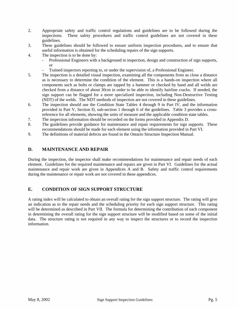
2. Appropriate safety and traffic control regulations and guidelines are to be followed during theinspections. These safety procedures and traffic control guidelines are not covered in theseguidelines.
3. These guidelines should be followed to ensure uniform inspection procedures, and to ensure thatuseful information is obtained for the scheduling repairs of the sign supports.
4. The inspection is to be done by:- Professional Engineers with a background in inspection, design and construction of sign supports,
or- Trained inspectors reporting to, or under the supervision of, a Professional Engineer.
5. The inspection is a detailed visual inspection, examining all the components from as close a distanceas is necessary to determine the condition of the element. This is a hands-on inspection where allcomponents such as bolts or clamps are tapped by a hammer or checked by hand and all welds arechecked from a distance of about 30cm in order to be able to identify hairline cracks. If needed, thesign support can be flagged for a more specialized inspection, including Non-Destructive Testing(NDT) of the welds. The NDT methods of inspection are not covered in these guidelines.
6. The inspection should use the Condition State Tables 4 through 9 in Part IV, and the informationprovided in Part V, Section D, sub-section 1 through 6 of the guidelines. Table 3 provides a cross-reference for all elements, showing the units of measure and the applicable condition state tables.
7. The inspection information should be recorded on the forms provided in Appendix D.8. The guidelines provide guidance for maintenance and repair requirements for sign supports. These
recommendations should be made for each element using the information provided in Part VI.9. The definitions of material defects are found in the Ontario Structure Inspection Manual.
D. MAINTENANCE AND REPAIR
During the inspection, the inspector shall make recommendations for maintenance and repair needs of eachelement. Guidelines for the required maintenance and repairs are given in Part VI. Guidelines for the actualmaintenance and repair work are given in Appendices A and B. Safety and traffic control requirementsduring the maintenance or repair work are not covered in these appendices.
E. CONDITION OF SIGN SUPPORT STRUCTURE
A rating index will be calculated to obtain an overall rating for the sign support structure. The rating will givean indication as to the repair needs and the scheduling priority for each sign support structure. This ratingwill be determined as described in Part VII. The formula for determining the contribution of each componentin determining the overall rating for the sign support structure will be modified based on some of the initialdata. The structure rating is not required in any way to inspect the structures or to record the inspectioninformation.

May 8, 2002 Sign Support Inspection Guidelines Pg. 6
III. INVENTORY, HISTORICAL AND ELEMENT DATA REQUIREMENTS
The inventory and historical data must be collected for each sign support. This information should beobtained prior to the inspection, but should also be verified during the inspection. Field measurements andobservations are required since a lot of the information may not be available from drawings, or the drawingsmay not exist. Most of the information is entered once, and does not change. Areas that are input by theinspector on an on-going basis, or areas that are calculated, are indicated. The inventory and historical datasheet is found in Appendix C. Also required is the initial setting up of the element groups, names andquantities. The following information is required:
A. INVENTORY DATA
MTO Site Number: The county and site number assigned to the structure, similar to that given to bridges.For counties with many sign supports, it may be preferable to begin the numberingwith 5000. This will differentiate the sign structures from bridges.
Structure Name: The sign name, typically determined by the message on the sign and/or the locationof the sign. Example, “Keele Street Advance Sign”. The terms to be used are:
i) Exit Sign - The sign at the point of exitii) Advance Sign - The sign warning of the upcoming exit.iii) Pre-Advance Sign - The first of two signs warning of the upcoming
exit.Location: A descriptive text telling where the structure is located.Comment: A descriptive text for any additional information that is needed on the sign. This includes the
configuration of the truss segments, the attachment locations for bridge mounted signs (i.e.barrier, fascia, or soffit), or other information that is of importance.
Direction: The direction of traffic under the sign and, if applicable, if the sign is at a core/collectorlocation. The direction should correspond to that given by IHIS and is defined as the generaldirection of the highway. In determining the structure orientation, and describing the rightand left-hand sides, the structure should be viewed facing the direction of traffic. Forstructures that span a two direction roadway, whether signs are present for both directions ornot, the structure should be viewed looking in the North or Eastbound direction and recordedas such.
Region: The MTO region in which the sign is located.District: The MTO district in which the sign is located.County: The regional municipality or county in which the sign is located.Old Site Number: The number given to the sign support structure under the previous inventory methods.Owner: The owner of the sign support structure.AADT: The AADT under the sign support structure.Inspection Route Sequence: The route number on which the sign is located. (This is not used by all of the
MTO Regions)Manufacturer: If known, enter the name of the manufacturer.Vertical Clearance: If known, enter the minimum vertical clearance to the lowest portion of the sign
support structure or any attachment.Latitude: The geodetic latitude obtained using a GPS unit and located at the centre of the right leg.Longitude: The geodetic longitude obtained using a GPS unit and located at the centre of the right leg.Sign Support Type: The type of sign support structure chosen from the list of standard types:
- Aluminum Tapered Leg (ATL) (formerly Type 1)- Aluminum Circular Leg (ACL) (formerly old Type 2)- Aluminum Rectangular Leg (ARL) (formerly LCMS Type or new Type 2)- Changeable Message Signs (CMS) - electronic sign panel integral with structure

May 8, 2002 Sign Support Inspection Guidelines Pg. 7
- TriChord (TC) - truss with 3 chords interlaced by diagonals and 2 legs- Plane Truss (PT) - truss with 2 chords and 2 legs- Cantilever (C) - truss with 2 chords and 1 leg- Single Arm Cantilever (SAC)- single arm and single leg- Butterfly (B) - single leg and 2 sets of arms in two directions- Pole Mounted (PM) - sign located in front of single leg- MonoTube (MT) - single arm with two legs- Bridge Mounted (BM2) - 2 connection points- Bridge Mounted (BM2S) - 2 connection points with Spacer truss- Bridge Mounted (BM3) - 3 connection points- Bridge Mounted (BM3S) - 3 connection points with Spacer truss- Other Overhead Structure- Other Bridge Mounted Structure- Other
Sign Type: The type of signboard. EitherAluminumPlywoodChangeable Message, orOther.
Left/Right Footing Type: The type of footing. EitherGround MountedBridge Mounted, orBarrier Mounted (i.e. Median).
Sign A, B, C (Height, Length, Colour, Overlay, Contents):Give the height, length and colour of the each sign on the structure. State (yes or no) whether analuminum overlay has been placed on the sign. Give the information appearing on the sign in thecontents field. There is space for three signs, starting from the left. This is used to determine the totalsign area, and can easily be checked to see if any additional sign have been erected. Small signs, suchas Hospital signs, Truck Restriction signs, Lane Marker Arrow Boards, should be included asattachments.
Total Sign Area: The area of all signs attached to the structure in square metres.Maximum Sign Area: The maximum allowable sign area for the sign. Some newer sign support structures
have the maximum sign area stamped onto the structure. For other structures, themaximum area can be obtained from the standard drawings. For the AluminumTapered Leg (ATL) sign supports, an evaluation of the original design found that themaximum area is 22.3 m2 (240ft2). Details of this can be found in the Memorandumissued by the Bridge Office on February 12, 1999 and reproduced in Appendix E.
Span: The span of the sign support structure. The span is measured from the centre of the left to rightsupport. For cantilever type signs, the span is defined as the distance from the centre of the leg tothe farthest edge of the arm. For bridge mounted sign supports, the span is defined as the lengthof the chord that is attached to the bridge. On older aluminum truss type sign supports, it may behelpful to estimate the span knowing that the typical panel size was 5 feet and trusses usually hadspan lengths in multiples of 5 feet. Generally, the span can be estimated by measuring a typicalpanel of the truss and counting the number of panels.
Attachments: List any other attachments that exist on the sign support structure. These include thefollowing: - Walkway arm - Grating
- Handrail - Illumination- Traffic light - Camera- Damping plate - Electrical Junction box- Small sign - Other

May 8, 2002 Sign Support Inspection Guidelines Pg. 8
B. HISTORICAL DATA
Year Built: If available, enter the year the structure was built.Contract Number When Built: The contact under which the sign support structure was built.Latest Biennial Inspection: The last time the structure was inspected. This value is carried forward from
inspection to inspection.Latest Specialized Inspection: The last time the structure was inspected using NDT or other more detailed
means.Latest Structure Rating: Based on the condition of the various components, an overall structure rating
is determined. This gives an indication of the relative condition of variousstructures. This rating is calculated by the system.
Latest Structure Condition: Based on the structure rating, the overall structure is placed into one of thefour condition states – either excellent, good, fair, poor.
Rehab. History: Enter the date and description of any rehab work that has been done to thestructure.
Regional Priority Number: Priority as determined by region.Programmed Work Year: Programmed work year as determined by region.Nature of Program Work: Brief description of required work as determined by region.
C. ELEMENT DATA
The complete list of element groups, element names, and quantities must be determined for each sign support.The table for completing the element inventory information is found in Appendix D. The first page inAppendix D contains overall information, with the Field Inspection Information completed before theinspection and the Additional Investigations Required being completed after the inspection. The ElementInformation on the second page (or the alternate form on the third page) must be completed for each structure.Each sign support does not necessarily contain all the elements. Table 1 lists the most common types of signsupports and lists whether the element exists or not. This can be used as a guide, however, it must be checkedin the field as not all elements exist as listed in the table. Table 3 contains a complete list of all possibleelements. The element table should be completed as described below:
Element Group: The description of the category in which the element belongs.
Element Name: The name of the element within the element group.
Location: If a certain location within the element is in significantly different condition that the remainder ofthe element, the inspection of the element can be separated by location. Typically when firstobtaining the element information the location is not used. When the element is split intolocations, usually as a result of the inspection, the quantity must be re-calculated for eachlocation.
Type: A brief summary of the nature or material composition of the element. For example; concrete,aluminum or steel, or C-Clamp or U-bolt. The possible Element Types are given in Table 3.
Quantity: The calculated total quantity of the element. The method of estimating certain quantities,especially those with large quantities, is given in Table 2. Some of the elements may requirefield counting or field measuring.

May 8, 2002 Sign Support Inspection Guidelines Pg. 9
TABLE 1: Possible Elements on Different Sign Support Types
Ele
men
t Gro
up
Ele
men
t Nam
e
Alu
min
um T
aper
ed L
eg (A
TL
)
Alu
min
um C
ircul
ar L
eg (A
CL
)
Alu
min
um R
ecta
ngul
ar L
eg (A
RL
)
Cha
ngea
ble
Mes
sage
Sig
n (C
MS)
Tri
-Cho
rd (T
C)
Can
tilev
er (C
)
Mon
o-T
ube
(MT
)
Brid
ge M
ount
ed (B
M)
1a. Concrete Y Y Y Y Y Y Y N1b. Steel Pedestal P P P N N N N N1c.
Foundation
Bearing Surface Y Y Y Y Y Y Y Y2a. Base Plate Y Y Y Y Y Y Y Y2b. Leg Y Y Y Y Y Y Y N2c. Corner Arc Y N N N N N N N2d.
Chord/MainMember
Horizontal Y Y Y Y Y Y Y U3a. Leg Y Y Y Y N N N N3b. Corner Arc Y N N N N N N N3c.
Diagonal
Truss Y Y Y Y Y Y Y N4a. Base Y Y Y Y Y Y Y Y4b. Leg N Y Y Y Y Y Y N4c. In Line Chord Y U Y Y U N Y N4d. Sign Y Y Y N Y Y U Y4e. Damping Assembly N N N N N U N N4f. Walkway Arm U U U N N N N N4g.
Connection
Accessory P P P N P P P P5a. Sign Y Y Y N Y Y U Y5b. Skin N N N Y N N N N5c. Damping Assembly N N N N N U N N5d. Walkway Arm U U U N N N N P5e. Walkway U U U Y N N N P5f. Handrail U U U Y N N N P5g.
Attachment
Other Accessory P P P P P P P P6a. Chords/Main Member N N N Y Y Y N N6b. Diagonals N N N N Y Y Y N6c.
Coating
Connections N N N N Y Y Y N
Y = Yes, element must existN = No, element cannot existU = usually, element is usually associated with this type of Sign SupportP = possibly, element is possibly associated with this type of Sign Support

May 8, 2002 Sign Support Inspection Guidelines Pg. 10
TABLE 2: Procedure for Determining Element QuantitiesElement Group Element Name
ATL
AC
L
AR
L
CM
S
TC C MT
BM
Count each foundation1a. Concrete2 2 2 2 2 1 2 0Count each1b. Steel Pedestal0-2 0-2 0-2 0 0 0 0 0
Bearing Surface Count each surface connecting structure to foundation1c.
Foundation
4 4 4 4 2 1 2 countEach segment of chord between field splices is counted as 1chord element
2a. Base Plate 4 4 4 4 2 1 2 count2b. Leg 8 4 4 4 2 1 2 02c. Corner Arc 8 0 0 0 0 0 0 02d.
Chord/MainMember
Horizontal 4T 4T+8 4T+8 12 3T 2 2 0-2Each diagonal is counted. The approximations below can beused for large quantities in lieu of counting.
3a. Leg 23 20 20 20 0 0 0 03b. Corner Arc 31 0 0 0 0 0 0 03c.
Diagonal
Truss 48*510' +−s
48*5'
+s
48*5'
+s 10*
2.3S 62 2*
8.2S 0 0
Count the connections4a. Base 4* 4* 4* 4 2 1 2 count4b. Leg 0 8 8 4 4 2 2 04c. In Line Chord 4T+12 4T+4 4T+4 8 4T-4 0 1 04d. Sign count count count count count count count count4e. Damping Assembly 0 0 0 0 0 count 0 04f. Walkway Arm# count count count 0 0 0 0 04g.
Connection
Accessory count count count count count count count countCount the attachments
5a. Sign 1-3 1-3 1-3 1-3 1-3 1-3 1-3 1-35b. Skin 0 0 0 5 0 0 0 05c. Damping Assembly 0 0 0 0 0 1 0 05d. Walkway Arm count count count 0 0 0 0 05e. Walkway## count count count count 0 0 0 count5f. Handrail### count count count count 0 0 0 count5g.
Attachment
Other Accessory count count count count count count count count6a. Chords/Main Member Sum the quantities of chord/main member elements (2a to 2d)6b. Diagonals Sum of the quantities of diagonal elements (3a to 3c)6c.
Coating
Connections Sum of the quantities of structural connections (4a-4c)* - If Steel Pedestals are present the quantity is double.T - The number of truss segments.s’ - Span in feet.S - Span in metres.# - Generally equal to twice the number of walkway arms.## - Each segment of grating is counted as a walkway element.### - Each handrail segment is counted as a handrail element.

May 8, 2002 Sign Support Inspection Guidelines Pg. 11
IV. INSPECTION OVERVIEW
The inspection of sign supports shall be done using the “severity and extent” philosophy. The various signsupports are divided into elements, and each element is inspected and recorded separately. Not all elementsexist on all sign supports. Table 3 is a cross-reference table that lists all elements, the materials involved, andthe condition state tables to be used. For all elements, the quantity to be measured is "Each". Each elementand each material has different potential defects. Condition state tables are provided for each type of material,which describes the potential defect, and categorizes the defects into four condition states – excellent, good,fair, and poor. Excellent and good condition states will be recorded together. Generally, the elements in Fairand Poor condition are noted and the remainder is noted in the Excellent/Good State. The definitions ofmaterial defects are found in the Ontario Structure Inspection Manual, although some have been repeated inthe condition state tables. Some elements refer to several condition state tables. These are in cases where theelement is composed of several materials, or if the list of defects could not be included in one table. Theinspector records the number of elements in each condition state for each element type. If several defects ofvarying severity are found in an element, the condition state defining the worst defect is selected. If morethan one table applies, the inspector uses several tables, and chooses the condition state that is the worst. Thefollowing are the condition state tables that apply to sign support structures:
Table 4: ConcreteTable 5: Metal (Steel and Aluminum)Table 6: Bolted ConnectionsTable 7: Bearing SurfacesTable 8: AttachmentsTable 9: Coatings
During the inspection, the inspector should verify the inventory quantities, especially for elements that areeasy to count. The sign areas and the number and type of attachments should be checked at each inspectionsince it is possible that these have been added or changed without notification. If the total sign area is greaterthan the maximum allowable sign area, the Regional Structural Section should be notified immediately. Other information should also be reviewed to check the accuracy of the inventory information. The inspectorshall also record the required maintenance item for the elements, as well as any repair items, including theurgency as described in Part VI. The number of occurrences should be noted along with the maintenance orrepair code number. All urgent maintenance or repair items shall be brought to the attention of the RegionalStructural Section immediately.
A complete inspection report shall include the following:- The completed and verified Inspection Form for Inventory.- The completed Inspection Form for General Inspection.- The competed Inspection Forms for Elements. All elements shall be inspected according to the
Condition State Tables, any performance deficiencies noted, maintenance and repair needs noted,along with the urgency and any comments made.
- Marking areas requiring repair with flagging tape or paint.- A photograph of the overall structure, as well as photographs of all areas in fair or poor condition.
May 8, 2002 Sign Support Inspection Guidelines Pg. 12
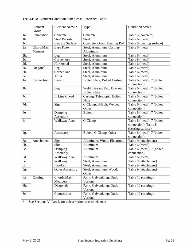
TABLE 3: Element/Condition State Cross-Reference Table
ElementGroup
Element Name * Type Condition States
1a. Foundation Concrete Concrete Table 5 (concrete)1b. Steel Pedestal Steel Table 6 (metal)1c. Bearing Surface Concrete, Grout, Bearing Pad Table 8 (bearing surface)2a. Base Plate Steel, Aluminum, Casting-
AluminumTable 6 (metal)
2b. Leg Steel, Aluminum Table 6 (metal)2c. Corner Arc Steel, Aluminum Table 6 (metal)2d.
Chord/MainMember
Horizontal Steel, Aluminum Table 6 (metal)3a. Leg Steel, Aluminum Table 6 (metal)3b. Corner Arc Steel, Aluminum Table 6 (metal)3c.
Diagonal
Truss Steel, Aluminum Table 6 (metal)4a. Base Bolted Plate, Bolted Casting Table 6 (metal), 7 (bolted
connection)4b. Leg Weld, Bearing Pad, Bracket,
Bolted PlateTable 6 (metal), 7 (boltedconnection)
4c. In Line Chord Casting, Telescopic, BoltedPlate
Table 6 (metal), 7 (boltedconnection)
4d. Sign C-Clamp, U-Bolt, Welded,Other
Table 6 (metal), 7 (boltedconnection)
4e. DampingAssembly
Bolted Table 6 (metal), 7 (boltedconnection)
4f. Walkway Arm C-Clamp Table 6 (metal), 7 (boltedconnection), Table 8(bearing surface)
4g.
Connection
Accessory Bolted, C-Clamp, Other Table 6 (metal), 7 (boltedconnection)
5a. Sign Aluminum, Wood, Electronic Table 9 (attachment)5b. Skin Aluminum Table 6 (metal)5c. Damping
AssemblyAluminum Table 6 (metal), 7 (bolted
connection)5d. Walkway Arm Aluminum Table 6 (metal)5e. Walkway Steel, Aluminum Table 9 (attachment)5f. Handrail Steel, Aluminum Table 9 (attachment)5g.
Attachment
Other Accessory Steel, Aluminum, Wood,Other
Table 9 (attachment)
6a. Chords/MainMembers
Paint, Galvanizing, Dual,Various
Table 10 (coating)
6b. Diagonals Paint, Galvanizing, Dual,Various
Table 10 (coating)
6c.
Coating
Connections Paint, Galvanizing, Dual,Various
Table 10 (coating)
* - See Sections V, Part D for a description of each element
May 8, 2002 Sign Support Inspection Guidelines Pg. 13
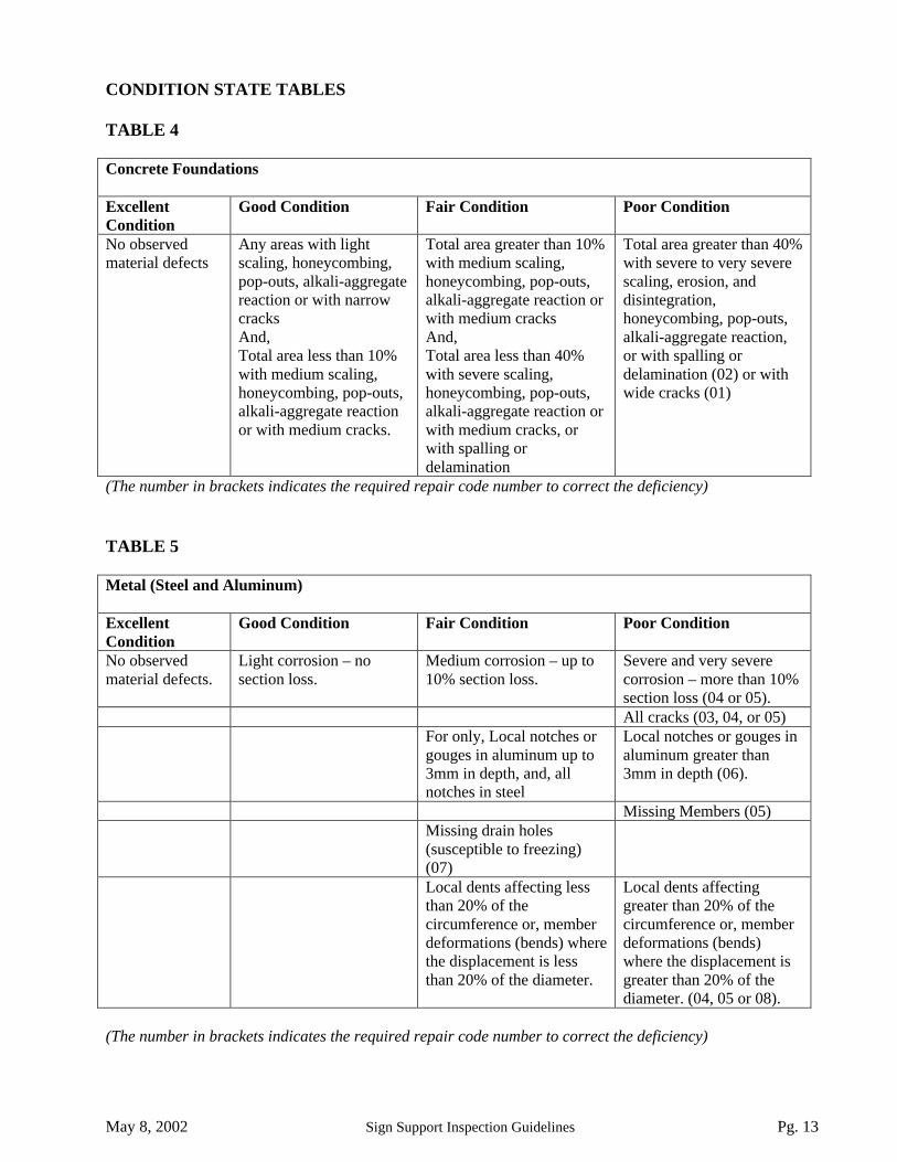
CONDITION STATE TABLES
TABLE 4
Concrete Foundations
ExcellentCondition
Good Condition Fair Condition Poor Condition
No observedmaterial defects
Any areas with lightscaling, honeycombing,pop-outs, alkali-aggregatereaction or with narrowcracksAnd,Total area less than 10%with medium scaling,honeycombing, pop-outs,alkali-aggregate reactionor with medium cracks.
Total area greater than 10%with medium scaling,honeycombing, pop-outs,alkali-aggregate reaction orwith medium cracksAnd,Total area less than 40%with severe scaling,honeycombing, pop-outs,alkali-aggregate reaction orwith medium cracks, orwith spalling ordelamination
Total area greater than 40%with severe to very severescaling, erosion, anddisintegration,honeycombing, pop-outs,alkali-aggregate reaction,or with spalling ordelamination (02) or withwide cracks (01)
(The number in brackets indicates the required repair code number to correct the deficiency)
TABLE 5
Metal (Steel and Aluminum)
ExcellentCondition
Good Condition Fair Condition Poor Condition
No observedmaterial defects.
Light corrosion – nosection loss.
Medium corrosion – up to10% section loss.
Severe and very severecorrosion – more than 10%section loss (04 or 05).All cracks (03, 04, or 05)
For only, Local notches orgouges in aluminum up to3mm in depth, and, allnotches in steel
Local notches or gouges inaluminum greater than3mm in depth (06).
Missing Members (05)Missing drain holes(susceptible to freezing)(07)Local dents affecting lessthan 20% of thecircumference or, memberdeformations (bends) wherethe displacement is lessthan 20% of the diameter.
Local dents affectinggreater than 20% of thecircumference or, memberdeformations (bends)where the displacement isgreater than 20% of thediameter. (04, 05 or 08).
(The number in brackets indicates the required repair code number to correct the deficiency)

May 8, 2002 Sign Support Inspection Guidelines Pg. 14
CONDITION STATE TABLES
TABLE 6
Bolted Connection
Excellent Condition Good Condition Fair Condition Poor Condition
All bolts tight Between 0 to 20% offasteners in connectionloose (12).Between 0 to 10% offasteners in connectioncracked, broken, ormissing+ (13).
Greater than 20% offasteners in connectionloose (12).Greater than 10% offasteners in connectioncracked, broken, ormissing+ (13).
All washers present Misaligned but tightbolts* or bolts missingwashers# (or smallwashers in oversizeholes) in less than 30% offasteners in connection.
Misaligned but tightbolts* (13) or boltsmissing washers# (orsmall washers inoversize holes) in over30% of fasteners inconnection (14).
Mating plates inExcellent condition.
Mating plates in Goodcondition (according toTable 5).
Mating plates in Faircondition (according toTable 5).
Mating plates in Poorcondition (according toTable 5) (03, 04, 05).
Mating plates in contactwith each other overentire surface
Mating plates withoutcontact with each otherover an area:- less than 10% of total
area for single(bending) members.
- less than 20% of totalarea for trussed (axialforce) members.
Mating plates withoutcontact with each otherover an area:- between 10% and
30% of total area forsingle (bending)members.
- between 20% and60% of total area fortrussed (axial force)members.
Mating plates withoutcontact with each otherover an area:- greater than 30% of
total area for single(bending) members(11).
- Greater than 60% oftotal area for trussed(axial force)members (11).
Misaligned but tightclamp.
Loose clamp (15). Cracked or brokenclamp (16).
* - Includes a bolt without proper thread engagement (the bolt is below the surface of the nut).+ - Includes Adhesive anchorage type bolts since the bond with the concrete has been broken.# - Only consider if missing washer appear to cause some bearing problems.
(The number in brackets indicates the required repair code number to correct the deficiency)
May 8, 2002 Sign Support Inspection Guidelines Pg. 15
CONDITION STATE TABLES
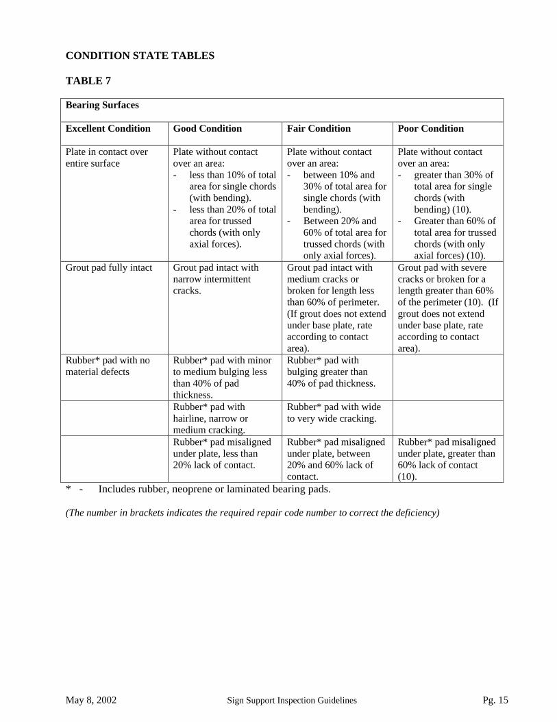
TABLE 7
Bearing Surfaces
Excellent Condition Good Condition Fair Condition Poor Condition
Plate in contact overentire surface
Plate without contactover an area:- less than 10% of total
area for single chords(with bending).
- less than 20% of totalarea for trussedchords (with onlyaxial forces).
Plate without contactover an area:- between 10% and
30% of total area forsingle chords (withbending).
- Between 20% and60% of total area fortrussed chords (withonly axial forces).
Plate without contactover an area:- greater than 30% of
total area for singlechords (withbending) (10).
- Greater than 60% oftotal area for trussedchords (with onlyaxial forces) (10).
Grout pad fully intact Grout pad intact withnarrow intermittentcracks.
Grout pad intact withmedium cracks orbroken for length lessthan 60% of perimeter.(If grout does not extendunder base plate, rateaccording to contactarea).
Grout pad with severecracks or broken for alength greater than 60%of the perimeter (10). (Ifgrout does not extendunder base plate, rateaccording to contactarea).
Rubber* pad with nomaterial defects
Rubber* pad with minorto medium bulging lessthan 40% of padthickness.
Rubber* pad withbulging greater than40% of pad thickness.
Rubber* pad withhairline, narrow ormedium cracking.
Rubber* pad with wideto very wide cracking.
Rubber* pad misalignedunder plate, less than20% lack of contact.
Rubber* pad misalignedunder plate, between20% and 60% lack ofcontact.
Rubber* pad misalignedunder plate, greater than60% lack of contact(10).
* - Includes rubber, neoprene or laminated bearing pads.
(The number in brackets indicates the required repair code number to correct the deficiency)

May 8, 2002 Sign Support Inspection Guidelines Pg. 16
CONDITION STATE TABLES
TABLE 8
Attachments
Excellent Condition Good Condition Fair Condition Poor Condition
No observed materialdefects
Sign support bracketwith light corrosion
Sign support bracketwith medium corrosion.
Sign support bracket withcracks or severe corrosion(18).
Sign support bracketfirmly attached to sign.Attachment clips orscrews in goodcondition.
Overall, sign supportbracket firmly attachedto sign, with a few looseor missing fasteners(17).
Sign support bracketloosely attached to sign –numerous loose or missingfasteners (17).
Sign panel with lightcorrosion.
Sign panel with mediumcorrosion or slightlybent or cracked, but signis still legible and nodanger of any portion ofsign panel coming off inhigh wind (17).
Sign panel with severerust, severely bent orcracked with sign illegibleand a possibility of aportion of sign panelcoming off in high wind(17 or 18).
No observed materialdefects
Grating firmly attachedto supports and withlight corrosion,
Grating with moderatecorrosion, loose, or withsmall part cracked or notbearing on the supportarms, but no danger ofgrating dislodging (17).
Grating with severecorrosion, severely loose,or with larger portionscracked or not bearing onthe support arms, withpossibility of gratingdislodging (17 or 18).
No observed materialdefects
Handrail , walkwayarm or other attachmentmember firmly attachedwith light corrosion
Handrail, walkway armor other attachmentmember with moderatecorrosion, or slightlyloose or bent, but nodanger of coming off(17).
Handrail, walkway arm orother attachment memberwith severe corrosion,excessively loose or bent,with a possibility ofcoming off or not beingable to support normal use(17 or 18).
No observed materialdefects
Minor accessory(luminaires, trafficsignals, cameras, etc.)with light corrosion.
Minor accessory withmoderate corrosion ormoderate defects, butstill appears to functionadequately (17).
Minor accessory withsevere corrosion, ordamage and it appears theaccessory may notfunction properly or maycome off (17 or 18).Missing sign panels orother attachments (18)
(The number in brackets indicates the required repair code number to correct the deficiency)

May 8, 2002 Sign Support Inspection Guidelines Pg. 17
CONDITION STATE TABLES
TABLE 9
Coating
Excellent Condition Good Condition Fair Condition Poor Condition
No observed materialdefect
Minor checking,cracking, alligatoring,chalking
Checking, cracking,alligatoring
Severe checking,cracking, alligatoring.(19 or 20).
Intercoat delamination,peeling (top coat only)
Undercutting, blisters,peeling (prime coat),underfilm corrosion (19or 20).
Signs of chemical attackOverspray, runs, sags,pinholing
Bridging, edge defects,shadows, pinpointrusting
RUST CONDITION*RATING CAT. 1
RUST CONDITION*RATING CAT. 2
RUST CONDITION*RATING CAT. 3
RUST CONDITION*RATING CAT. 4 orhigher
* - Rust Condition Ratings are defined in the Structural Steel Coating Manual (Figures showing the RustCondition Rating Categories are shown below)
Category 1: No Rust Category 2: Light Surface RustCondition State: Excellent Condition State: Good
Category 3: Medium Surface Rust Category 4: Severe Surface RustCondition State: Fair Condition State: Poor
(The number in brackets indicates the required repair code number to correct the deficiency)

May 8, 2002 Sign Support Inspection Guidelines Pg. 18
V. INSPECTION DETAILS
The inspection of the structures is to be a detailed visual inspection inspecting every area of everyelement in the truss. Table 3 provides a summary of all the elements, as well as the condition statetable to use with each element. This part of the guidelines describe the inspection requirements inmore detail. This includes:
i) What is included with which element.ii) For which sign support structure the element exists.iii) Some guidance in determining the quantity.iv) What to look for during the inspection of the element.v) Potential maintenance requirement for the element (also see Part VI).vi) Potential performance deficiencies for the element (also see Part VI).
The inspector is to complete the forms in Appendix D. These are for any additional investigations required,field inspection information, as well as the severity and extent information for each element. The followinginformation must be entered by the inspector:
A. FIELD INSPECTION INFORMATION
Date of Inspection: The date the inspection is completed.Inspector: The party chief in the inspection.Others in Party: The other members of the inspection party.Equipment used: Any specialized equipment used.Weather: The weather conditions.Temperature: The temperature.
B. ELEMENT INFORMATION
The top part of the element information (or the left part of the alternate form) must be entered only once, atthe inventory stage, and then the information is carried forward for future inspections. The inspector mustenter the information on the lower part of the element sheet (or the right part of the alternate form) at eachinspection. The number of elements in each condition state must be recorded with the excellent and goodcondition states recorded together. Generally, the number of elements in the Fair and Poor condition state arenoted and the remainder are recorded in the Excellent/Good State. The inspector also must record the numberof occurrences and code numbers for both the maintenance and repair items along with the urgency. Allurgent maintenance or repair items shall be brought to the attention of the Regional Structural Sectionimmediately.
C. ADDITIONAL INVESTIGATIONS
After completion of the inspection of an element, or the entire structure, the inspector can makerecommendations for further investigations to be done. The inspection of the structures is to be a detailedvisual inspection involving the inspection of every area of every element in the truss. Additionalinvestigations should not be specified to avoid inspection of the entire structure. They should be used in caseswhere the extent of cracking or the effect of deformed members cannot be determined by the inspector. Inthese cases the inspector may indicate, by the use of a performance deficiency (02), that further additionalinvestigations are to be done to certain elements. The inspector shall determine the needed investigation, aswell as the urgency. Areas where Non Destructive Testing (NDT) may be beneficial include (but are notrestricted to):

May 8, 2002 Sign Support Inspection Guidelines Pg. 19
- Ultrasonic testing (UT) of the anchor bolts- Liquid Penetrant Testing (LPT) of welds around base plates and possibly steel pedestals.- LPT of diagonal to chord welds, especially for diagonals welded to aluminum cluster castings that are
present on many aluminum sign supports.- Areas and welds adjacent to impact damage.
If the inspectors feel that a defect may be significant enough to affect the immediate overall strength of thesign support, or a major component of the sign support, the suspected performance deficiency in structuralcapacity (05) should be indicated.
Also entered in this location are any special notes or general comments for the sign support structure. Theseshould be general comments that apply to the overall sign support and not to specific elements.Recommendations related to the overall sign support can also be made in this location.
D. INSPECTION – ELEMENT DETAILS
The inspection of all elements is required. As described in the Repair Section (Part VI), defects that are to berepaired should be marked (with flagging tape or paint) to allow the defects to be found easily in the futurewhen they are to be repaired. A photograph of all areas in fair or poor condition should be taken and includedwith the inspection report. The following sub-sections describe the details of each element in the sign supportstructure, including what to look for and what is included with each element:
1a. FOUNDATION – CONCRETE
All concrete portions of the foundation should be inspected under this item. Inspect the exposedportion of the concrete foundation. Determine the condition state of each foundation according toTable 4. As described in Table 4, a more serious defect over a relatively small area will not lead to assevere of a condition state since the concrete is very good at redistributing loads.
i) Typically, this element group includes the circular or rectangular projection of the foundationabove the soil.
ii) For barrier mounted sign supports, a segment of barrier wall approximately 2 metres longcentred about the leg shall be inspected as the pedestal. This corresponds approximately withthe reinforced portion of the barrier wall. There are typically construction joints where thebarrier ends and the foundation pedestal begins.
iii) For bridge-mounted legs of sign support structures, the projecting pedestal on which the leg isattached shall be inspected as the pedestal.
If the foundation is tilted or has appeared to move, a performance deficiency for tilted/shiftedfoundation (01) shall be noted. This can either be noticed at the foundation itself or it may beevidenced by a sag in the span of the structure resulting from the foundation movement. If thefoundation is entirely covered in soil, the maintenance action to regrade soil (02) shall be noted.
1b. FOUNDATION – STEEL PEDESTAL
In some cases, a steel pedestal has been placed under the standard height leg to account for originalelevation differences. This is typically seen only on ATL Type sign supports. Each such pedestalshould be inspected according to Table 5. The condition of the pedestal is determined from thecondition of the worst member within the pedestal. The connections of the leg to the steel pedestal

May 8, 2002 Sign Support Inspection Guidelines Pg. 20
and the steel pedestal to the concrete shall be included as a Connections at the Base while only thecontact of the concrete to the pedestal should be included with the Foundation - Bearing Surface. Ifthe base connection is covered in soil or debris, the maintenance action of cleaning the base (01) shallbe recorded.
1c. FOUNDATION – BEARING SURFACE
Inspect the surface between the structure and the concrete foundation pedestal. The structure is eitherbearing directly (or through a steel pedestal) on the concrete foundation pedestal, bearing on a groutpad on top of the concrete foundation pedestal, or bearing on a rubber bearing pad. Each surface withbearing on the concrete shall be inspected; thus, each trussed leg accounts for 2 bearing surfaces. Thebearing surface should be inspected according to Table 7. This surface is inspected since defects inthis area can cause overload of the anchorage, base connection and possibly the legs.
i) For some older structures and most newer structures, where the base plate of the structure (orthe steel pedestal) sits directly on the concrete surface, the bearing surface is inspected forproper bearing on the foundation.
ii) For the many older structures, the base plate of the structure (or the steel pedestal) issupported on a grout pad. The bearing surface is affected by the condition of the grout pad.Poor grouting practices have been a common problem. On many sign supports, the baseshould have been placed on levelling nuts or washers, with the space under the base platefilled or injected with grout. Often, this was not the case as the grout was simply placed in afillet around the perimeter of the base plate with a trowel, providing no benefit to the bearingarea. On structures that exhibit breaking up of the grout, it shall be determined if the groutextends under the base plate. The inspection should rate not only the grout, but also thedegree of bearing.
iii) For bridge mounted sign supports, inspect the surface at each connection to the bridge. Thisis normally a steel plate bearing against a concrete surface.
iv) Some structures have a rubber bearing pad under the base plate to absorb small irregularitiesin the concrete surface and to provide damping to the structure. The condition of the bearingpad material should be inspected for cracking, bulging or tearing. The bearing pad is verythin and can only compensate for small irregularities. If gaps appear between the base plateand the bearing pad, the inspection should also include the effect on the degree of bearingcontact.
2a. CHORDS/MAIN MEMBER – BASE PLATE
Inspect the base plate or base castings. Chords/Main Members refer to members that are connectedby diagonals as well as longer single members such as single legs or single arms. Inspection shouldbe according to Table 5 for steel and aluminum. Each chord rating should be based on the worstdefects that are present.
i) For tapered leg structures, there are 2 aluminum casting base plates per leg.ii) For most other sign supports with trussed legs, there are 2 welded base plates, with stiffeners,
per leg.iii) For mono-tube and many newer sign supports where a single vertical column exists, there is
one base plate per leg.

May 8, 2002 Sign Support Inspection Guidelines Pg. 21
If the base plate is covered in soil or debris, the maintenance action of cleaning the base (01) shall berecorded. The inspector should look for corrosion or cracks in the base plate or castings and anystiffener plates.
2b. CHORDS/MAIN MEMBER – LEG
Inspect the leg chords of the sign support structure. Inspection should be according to Table 5 forsteel and aluminum. Each chord rating should be based on the worst defects in the length of thechord.
iv) For tapered leg structures, there are 4 chords per leg. The leg does not include the corner arcportion, but only the straight tapered portion of the leg.
v) For other sign supports where two columns are trussed together, there are 2 chords per leg.vi) For mono-tube and many newer sign supports, a single vertical column exists and the
inspection should be for each leg (main member).
Missing hand hole covers or chord caps should be replaced as a maintenance item (04), as a missingcover will allow corrosive salts to enter the legs. The inspector should look for cracks in the chord.Special attention should be given to attached clamps, which often lead to significant section loss dueto galvanic corrosion. Areas of galvanic corrosion should be marked as a performance deficiency(03) and marked with a maintenance item to remove the clamps (03) that are the cause of galvaniccorrosion. Bent members due to erection damage or vehicle collision are also possible. Shop spliceareas should also be inspected for this element.
2c. CHORDS/MAIN MEMBER – CORNER ARC
Inspect the chords of the corner arc portion of the structure. Inspection should be according to Table5 for steel and aluminum. Each entire chord segment should be inspected, with the rating based on theworst defects in each chord.
i) This element only exists for tapered leg structures where there are 4 chords per corner arc.
Missing hand hole covers or chord caps should be replaced as a maintenance item (04), as a missingcover will allow corrosive salts to enter the legs. The inspector should look for cracks in the chord.Special attention should be given to attached clamps, which often lead to significant section loss dueto galvanic corrosion. Areas of galvanic corrosion should be marked as a performance deficiency (03)and marked with a maintenance item to remove the clamps (03) that are the cause of galvaniccorrosion. Bent members due to erection damage or vehicle collision are also possible. Shop spliceareas should also be inspected for this element.
2d. CHORDS/MAIN MEMBER – HORIZONTAL
Inspect the truss chords or arms of the structure. Inspection should be according to Table 5 for steeland aluminum. Each chord rating should be based on the worst defects in the length of the chord in asegment between field splices.
i) For ATL sign supports, there are 4 chord elements per truss segment (the top-front, top-back,bottom-front and bottom back). The truss is taken to begin at the end of the corner arc.

May 8, 2002 Sign Support Inspection Guidelines Pg. 22
ii) For ACL and ARL sign supports, there are 4 chord elements per truss segment plus anadditional 4 chords at each end (from the connection to the leg until the first in-line (cluster)connection).
iii) For the CMS type sign supports there are 4 truss segments in the centre portion as well as ateach end. For the end segments, the truss is bent or angled with a shop weld being present.For the centre portion, much of the inspection must be done from the inside since thestructure is covered with a sheet aluminum skin.
iv) For tri-chord sign supports, there are 3 chord segments per truss segment (the top, bottom,and middle).
v) For Plane truss structures and cantilever sign supports, there are typically 2 chords.vi) For mono-tube signs, or other horizontal arms that do not contain truss-work, each chord
segment between field splice should be inspected as an element.
Missing end caps should be replaced as a maintenance item (04), as a missing cover will allowcorrosive salts to enter the chords. The inspector should look for cracks in the chord. Specialattention should be given to attached clamps, which often lead to significant section loss due togalvanic corrosion. Areas of galvanic corrosion should be marked as a performance deficiency (03)and marked as a maintenance item to remove the clamps (03) that are the cause of galvanic corrosion.Bent members due to erection damage or vehicle collision are also possible. Shop splice areas shouldalso be inspected for this element.
3a. DIAGONALS - LEG
Inspect the diagonals in the legs of the sign support. Inspection should be according to Table 5 forsteel and aluminum. Each diagonal should be inspected, including diagonals in all planes oforientation. This quantity was chosen since, it is convenient for both inspection and when repair isrequired. The welds at the member ends are included with this element. If cracks or other defectsoccur in the weld, the rating of the diagonal should be reflected by this defect. If it appears that thecrack may propagate into the chord or the connection, the condition that element should also reflectthat condition of this defect. The quantities of diagonals are quite large and Table 2 can be used as anapproximation.
i) For tapered leg structures, there are diagonals between all 4 chords in the tapered portion ofthe leg.
ii) For other sign supports with two columns are trussed together, there are diagonals betweenthe 2 chords in the leg. There are about 10 diagonals per leg.
iii) For mono-tube and many of the newer sign supports with a single vertical column, there areno diagonals and this element does not exist.
The inspector should look for cracks in the diagonals. Special attention should be given to attachedclamps, which often lead to significant section loss due to galvanic corrosion. Areas of galvaniccorrosion should be marked as a performance deficiency (03) and marked as a maintenance item toremove the clamps (03) that are the cause of galvanic corrosion. Bent members due to erectiondamage or vehicle collision, and cracking of members due to water filling the tubes and freezing, arealso possible.Diagonals susceptible to filling with water should be marked for the repair need of drilling a drainhole (07). This applies only for members that have the possibility of filling with water. This includesonly those members that are closed ended at the bottom with no drain holes, and either open-ended orclosed ended with drain (or vent) holes at the top. If no drain (or vent) holes are visible it is possiblethat there is internal venting and filling with water is not possible. It may also be possible to tap themember to determine if it is filled with water.

May 8, 2002 Sign Support Inspection Guidelines Pg. 23
3b. DIAGONALS – CORNER ARC
Inspect the diagonals in the corner arc portion of the sign support. Note that this element only existsfor tapered leg structures. Inspection should be according to Table 5 for aluminum. Each diagonalshould be inspected, including the diagonals in all planes of orientation. This quantity was chosensince, it is convenient for both inspection and when repair is required. The welds at the member endsare included with this element. If cracks or other defects occur in the weld, the rating of the diagonalshould be reflected by this defect. If it appears that the crack may propagate into the chord or theconnection, the condition that element should also reflect that condition of this defect.
The inspector should look for cracks in the diagonals. Special attention should be given to attachedclamps, which often lead to significant section loss due to galvanic corrosion. Areas of galvaniccorrosion should be marked as a performance deficiency (03) and marked as a maintenance item toremove the clamps (03) that are the cause of galvanic corrosion. Bent members due to erectiondamage or vehicle collision, and cracking of members due to water filling the tubes and freezing, arealso possible.Diagonals susceptible to filling with water should be marked for the repair need of drilling a drainhole (07). This applies only for members that have the possibility of filling with water. This includesonly those members that are closed ended at the bottom with no drain holes, and either open-ended orclosed ended with drain (or vent) holes at the top. If no drain (or vent) holes are visible it is possiblethat there is internal venting and filling with water is not possible. It may also be possible to tap themember to determine if it is filled with water.
3c. DIAGONALS - TRUSS
Inspect the diagonals in the legs of the sign support. Inspection should be according to Table 5 forsteel and aluminum. Each diagonal should be inspected, including the diagonals in all planes oforientation. This quantity was chosen since it is convenient for both inspection and when repair isrequired. The welds at the member ends are included with this element. If cracks or other defectsoccur in the weld, the rating of the diagonal should be reflected by this defect. If it appears that thecrack may propagate into the chord or the connection, the condition that element should also reflectthat condition of this defect.
i) For most aluminum structures, there are 4 chords with diagonals between all chords,including the gravity diagonals (visible on elevation), the wind diagonals (visible in plan) andthe inside diagonals. This amounts to several dozen, up to about a hundred, diagonals pertruss. The truss is taken to begin at the end of the corner arc. A common defect is crackingof the diagonal where it is welded to the cluster connection. Trapped water leads to corrosionof the aluminum cluster casting, which leads to cracking of the welds that connect thediagonal to the cluster. An example of this is shown in Figure 4c.1.
ii) For the CMS type sign supports, much of the inspection must be done from the inside sincethe structure is covered with a sheet aluminum skin.
iii) For tri-chord sign supports, there are 3 chords with several dozen diagonals between them.iv) For Plane truss structures and cantilever sign supports, there are 2 arms with only a few
diagonals between them, only in one plane. There are thus only 6 or 8 diagonals per truss, upto about 20 for plane truss structures.
v) For mono-tube signs, or other horizontal arms that do no contain truss-work, there are nodiagonals and this element does not exist.
The inspector should look for cracks in the diagonals. Special attention should be given to attachedclamps, which often lead to significant section loss due to galvanic corrosion. Areas of galvanic
May 8, 2002 Sign Support Inspection Guidelines Pg. 24
corrosion should be marked as a performance deficiency (03) and marked as a maintenance item toremove the clamps (03) that are the cause of galvanic corrosion. The inspection should alsoconcentrate on cracked welds in the areas around welded attachments. Bent members due to erectiondamage or vehicle collision, and cracking of members due to water filling the tubes and freezing, arealso possible.Diagonals susceptible to filling with water should be marked for the repair need of drilling a drainhole (07). This applies only for members that have the possibility of filling with water. This includesonly those members that are closed ended at the bottom with no drain holes, and either open-ended orclosed ended with drain (or vent) holes at the top. If no drain (or vent) holes are visible it is possiblethat there is internal venting and filling with water is not possible. It may also be possible to tap themember to determine if it is filled with water.
4a. CONNECTION - BASE
Inspect the connection at the base of the structure. The inspection should be according to Table 5 fora material of steel or aluminum and Table 6 for the bolts. The connection condition is based on theworst component within each connection.
i) For most situations, the base connection includes the base plates and stiffeners, as well as theanchor bolts.
ii) For many aluminum legged sign supports, the base connection includes the base casting, andthe anchor bolts.
iii) Each connection at the base of the column should be inspected. Thus, single column legshave 1 connection per leg, trussed legs have 2 connections per leg, and structures with steelpedestals have connections of the base plate to the pedestal as well as the pedestal to theconcrete anchorage.
iv) For bridge mounted sign supports, inspect the plates and bolts used to attach the structure tothe fascia and soffit of the bridge. Each connection point should be inspected. Several bridgemounted structures have shown problems with the connection to the bridge. Currentstandards call for ¾ inch (19mm) bolts to be used for the connection. If smaller diameterbolts or studs exist, especially if the sign is not up against the bridge fascia, a suspectedperformance deficiency (04) should be noted. If the projection of the stud beyond bracketsappears excessive, the suspected performance deficiency of improper embedment (06) of thestuds should be noted.
If the base connection is covered in soil or debris, the maintenance action of cleaning the base (01)shall be recorded. The inspector should look for loose nuts or bolts and corroded or cracked bolts.Loose bolts may be determined by tapping each bolt with a hammer. For stud type anchorages, if theprojection of the stud beyond base plate appears excessive, the suspected performance deficiency ofimproper embedment of the studs (06) should be noted.
4b. CONNECTION – LEG
Inspect the connection of the truss chords to the leg chord. Inspection should be according to Table 5for steel and aluminum, and Table 6 for the bolts, and Table 7 for the connection surfaces. Eachconnection of a truss chord to the leg chord should be inspected. The connection includes all bolts,end plates and stiffeners, brackets and castings.
i) For tapered leg sign supports, this type of connection does not exist. All connections areconsidered in-line chord connections.

May 8, 2002 Sign Support Inspection Guidelines Pg. 25
ii) For ACL and ARL aluminum sign supports, the connection of the 4 truss chords to the 2 legcolumns should be included for this element. It should include all plates, and welds in thechord to leg area. This is a welded shop connection and not a field splice.
iii) For the CMS sign supports, the element includes the cap plates, saddles, bolts, and thebearing pad between the steel leg and the aluminum truss.
iv) For tri-chord sign supports, the connection of the front chord to the single leg should beincluded in this element. It includes the chord surface, steel brackets, the locking, hold-downand clamping plates, bolts, and the rubber gasket. Since the chord and steel brackets aresignificantly more important in the connection area, the condition of each connection shallonly be deemed to be poor if it is due to the condition of the chord and steel brackets. If thegoverning component within the element is the locking, hold-down and clamping plates,bolts, or the rubber gasket, the condition of the connection should be recorded as no worsethan fair, unless the inspector feels there is an effect on the load carrying capacity.
v) For the cantilever sign support, the connection of the two arms to the single leg is included inthis element. It includes the end plates, stiffener plates, and the bolts.
The inspector should look for cracks in any of the plates or castings. The inspector should alsoconcentrate on loose bolts, which can have a serious effect on the strength of the connection. Also,bolts in connections with poor connection surfaces may be exposed to a more severe environment andthese areas should be inspected carefully for corrosion. If there is debris at the location of theconnection, the maintenance item to clean the debris (01) should be noted.
4c. CONNECTION – IN LINE CHORD
Inspect the field splice connections of the truss chords. Inspection should be according to Table 5 forsteel and aluminum, and Table 6 for the bolts and Table 7 for the connection surfaces. Eachconnection of a truss chord should be inspected. The connection includes all bolts, end plates andstiffeners, and castings.
i) For most aluminum sign supports, the field connection of the chords includes the aluminumcastings and the long bolts. All connections should be inspected. For ATL Type signsupports, this includes the connections on the leg, at either end of the corner arc portion, aswell as on the truss. For the ACL and ARL Type, there are only connections on the trussportions. A common defect is a loose bolt in the cluster connection, as shown in Figure 4c.2.
ii) For CMS signs, the connection is a telescopic one, with one chord segment inside of theother. The bolts through the chords must be tightened since this is a slip resistant connection.There is typically one connection on each chord at each end of the sign component.
iii) For tri-chord sign supports, the connection includes the end plates, stiffener plates, and bolts.iv) For the cantilever sign support, typically, there are no chord to chord connections.
The inspection should look for cracks in any of the plates or castings. The inspection should alsoconcentrate also on loose bolts, which can have a serious effect on the strength of the connection.Also, bolts in connections with uneven mating of plates may be exposed to a more severeenvironment and these areas should be inspected carefully for corrosion.
4d. CONNECTION – SIGN
Inspect the clamps used to attach the sign to the structure. Inspect the clamps according to Table 5, 6and 7. This item includes the C clamp casting as well as the bolts or U bolts. Each clamp should beinspected.
May 8, 2002 Sign Support Inspection Guidelines Pg. 26
i) In older and aluminum signs, these connections are C clamps.ii) In newer steel sign supports, these connections are U-bolts.iii) The Changeable Message Sign has the sign component built integral with the structural
members. No real attachment points are definable and thus, this element does not exist.iv) Other attachment methods may be possible. For example, on mono-tube sign supports,
brackets are welded to the chord. These brackets shall be inspected under this element.v) For bridge mounted signs, connection of the sign to the chord should be inspected in this
element. These are typically C clamps.
4e. CONNECTIONS – DAMPING ASSEMBLY
Inspect the attachment of the damping assembly brackets to the sign. The damping assemblyconnection exists only on Cantilever Sign Supports, and this element does not exist for the other typesof sign supports. Typically, there are two aluminum angle members connected to the aluminum “Z”shape of the sign. The connection is by means of smaller structural bolts. The attachment of eachpair of angle brackets should be inspected in accordance with to Tables 4 and 5. Typically, there areabout 3 to 5 pairs of such brackets per sign with 3 bolts per connection.
4f. CONNECTIONS – WALKWAY ARM
Inspect the clamps used to attach the walkway support arms to the structure. In older signs, theconnections are by means of C-clamps. This item includes the C clamp casting as well as the bolts.Inspect the clamps, or other means of connection, according to Table 5 and 6. The unit of inspectionfor this element shall be each clamp.
i) For most sign supports, the connection is to the truss chord.ii) For bridge mounted sign supports, these connections connect the walkway to the horizontal
chords. Actually, in bridge mounted sign supports, the chords are supported by the armsthrough these connections. The actual connection of the walkway to the bridge is coveredunder another element.
A common defect for the aluminum sign supports is shown in Figure 4f.1. The aluminum castingclamp is known to be susceptible to cracking on the flanges of the clamps if they were over tightened.
4g. CONNECTIONS – ACCESSORY
Inspect the clamps or other means used to attach any accessories to the structure. Inspect accordingto Table 5 and 6. Each clamp or attachment location should be inspected.
5a. ATTACHMENT – SIGN
Inspect the sign panel and sign brackets. The brackets, which attach the sign to the chord (at the signconnection), should be inspected according to Table 8. Similarly, the attachment of these brackets tothe sign itself should be inspected. This is done by screws or clips, or other means. The sign panelshould be inspected for impact damage and weathering. Each sign should be inspected as one unitsince, in many cases, defects will result in the removal and replacement of the entire sign component.
May 8, 2002 Sign Support Inspection Guidelines Pg. 27
5b. ATTACHMENT – SKIN
For Changeable Message Sign Supports, an aluminum skin covers the electronic portion of the sign,including the chords and diagonals. Typically, this thin sheet aluminum is welded continuously to thechords to provide a sealed enclosure. For convenience, each of the five surfaces of the skin areinspected (top, bottom, back, and sides). The inspection should be according to Table 5. Theinspection should concentrate on cracks and corrosion of the areas adjacent to welds and locations ofwater leakage. A maintenance item should be indicated to seal a leak (05) if there is evidence thatwater is leaking into the enclosure.
5c. ATTACHMENT – DAMPING ASSEMBLY
Inspect all components of the damping assembly. The damping assembly exists only on CantileverSign Supports, and this element does not exist for other sign supports. The damping assembly is toprovide for aerodynamic damping, to ensure that the sign support does not undergo gallopingvibration in the wind. The damping assembly includes the aluminum angle brackets, the plate, and allbolts used to connect these parts. The inspection should be according to Table 5 for the aluminummembers and Table 6 for the connections within the assembly. Each entire damping assembly shouldbe inspected as one unit, with the condition of the overall assembly governed by the worstcomponent.
5d. ATTACHMENT – WALKWAY ARM
Inspect the walkway arms. The walkway arms connect to the chords and support the grating. Theinspection should be according to Table 5. This element only exists for most aluminum type signsupports and bridge mounted signs. For bridge mounted signs, this element includes all the arms andstruts that connect the walkway and/or sign to the supports at the bridge. For CMS sign supports, thegrating is supported directly on the diagonals and this element does not exist. For other sign supports,a grating is not supplied and this element does not exist.
5e. ATTACHMENT – WALKWAY
Inspect the walkway assembly, including the grating and grating attachment. The inspection shouldbe according to Table 8. Each segment of the walkway should be inspected as one unit, including theconnection of the segments to each other and to the structure. On the aluminum sign supportstructures and bridge mounted sign supports, the walkway segments are typically about 5 feet (1.5m)long.
5f. ATTACHMENT – HANDRAIL
Inspect the handrail and handrail attachments. The inspection should be according to Table 8. Eachdiscrete portion of the handrail assembly should be inspected. For the aluminum sign supports andbridge mounted sign supports, there are typically about 5 to 10 handrail segments at a spacing ofabout 10 feet (3.0m). The handrail segments can fold down when not in use. On ChangeableMessage Signs there are typically two handrail segments (one on each side).

May 8, 2002 Sign Support Inspection Guidelines Pg. 28
5g. ATTACHMENT – OTHER ACCESSORY
Inspect any attached traffic signals, luminaires, cameras, etc. The taper truss (or spacer truss) onbridge mounted sign supports would be inspected as this element. Also the door on CMS type signsupports, or other items that are deemed important, can be inspected under this element. Thedescription of the element would go under the location of the element. Each of these attachmentsshould be inspected for overall looseness or damage according to the descriptions in Table 8.
6a. COATING – CHORDS/MAIN MEMBERS
Inspect the coating of the truss chords and main single members of the sign support for both the legsand the horizontal portion. The coating can either be galvanizing, paint, or a dual system ofgalvanizing and coating. If chords/main members exist with different coating types (i.e. galvanizedfor the horizontal portion and dual for the legs) then the type can be classified as "various" oralternately, the element can be separated into several locations. Several locations can also be used ifcertain areas are in worse condition than others. Most aluminum members do not have a coatingcategory, while most steel members have paint, galvanizing or a dual coating. The coating for eachchord segment should be inspected according to Table 9. Only the chords that have a coating need beconsidered and thus this quantity only equals the sum of the quantities in elements 2b, 2c and 2d (theChord/Main Member elements for the leg, corner arc and horizontal) when all are coated. Where adual system exists, the condition should be based on the condition of the inner coating.
6b. COATING – DIAGONALS
Inspect the coating of the diagonals of trussed members of the sign support, including in the leg,corner arc and horizontal truss. The coating can either be paint or galvanizing or a dual system ofgalvanizing and coating. If diagonal members exist in with different coating types (i.e. galvanized forthe truss portion and dual for the leg diagonals) then the type can be classified as "various" oralternately, the element can be separated into several locations. Several locations can also be used ifcertain areas are in worse condition than others. Most aluminum members do not have a coatingcategory, while most steel members have paint, galvanizing or a dual coating. The coating for eachdiagonal should be inspected according to Table 9. Only the diagonals that have a coating need beconsidered and thus this quantity only equals the sum of the quantities in elements 3a, 3b and 3c (thediagonal elements for the leg, corner arc and horizontal) when all are coated. Where a dual systemexists, the condition should be based on the condition of the inner coating.
6c. COATINGS – CONNECTIONS
Inspect the coating of the connections of the sign support. The coating can either be paint orgalvanizing or a dual system of galvanizing and coating. If diagonal members exist in with differentcoating types (i.e. galvanized for the truss connections and dual for the base connection) then the typecan be classified as "various" or alternately, the element can be separated into several locations.Several locations can also be used if certain areas are in worse condition than others. Most aluminummembers do not have a coating category, while most steel members have paint, galvanizing or a dualcoating. The coating for all structural connections should be inspected according to Table 9. Onlythe connections that have a coating need be considered and thus this quantity only equals the sum ofthe quantities in elements 4a, 4b and 4c (the base connections, the connections to the leg andconnections for in line chords) when all are coated. Where a dual system exists, the condition shouldbe based on the condition of the inner coating.

May 8, 2002 Sign Support Inspection Guidelines Pg. 29
VI. MAINENTANCE AND REPAIR
After the inspection of the element, the inspector must decide on whether a repair is required, and the urgencyof the repair. The need for repair and the urgency depend on the element and on the number of defects withinthat element. Generally, repairs are required only if the element is in poor condition. Some minor repairssuch as tightening bolts or replacing clamps are sometimes required for a non-poor condition but the urgencywould not be very high.
For the purposes of these guidelines, maintenance items are related only to the durability of the structures, anddo not have an immediate effect on the strength of the structure. Repair includes items that are predominantlyintended to increase the immediate strength or performance of the structure. Many repair items, such as repairof cracked members, are much more involved and typically require a contract to be completed. Some repairitems are relatively simple to perform (such as tightening bolts, replacing clamps, or applying touch-up paint)but are included as repair items due to their relative importance in the strength of the structure. These items(items 07, 12, 13, 14, 15, 16, 17 and 19 in Appendix D) can probably be performed by a small crew andwould not normally require a contract.
The 2-digit code for standard maintenance and repair items can be found on the Inspection Form in AppendixD. The required repair code is also found next to the defects in the Condition State Tables. Maintenanceitems do not appear in the Condition State Tables since these items are durability items and do notimmediately affect the condition of the elements. Besides the Condition State Tables, Tables 10 and 11 listall the elements with the most common defects and repairs or maintenance that are required. Table 10 can beused for maintenance and Table 11 can be used for repair items. The inspector can use judgement inrecommending either alternate or additional maintenance or repair work or differing urgency. Adescription of the actual procedures to be followed when doing the various types of maintenance actions andrepair work are provided in Appendix A and B respectively.
The repairs listed in the following sections are intended to restore the structure to its original, or near original,condition. However, as stated in the 1999 Bridge Office memorandum, and reproduced in Appendix E, manyaluminum sign support structures are not able to carry larger sign areas. For these cases, the repairs areconsidered temporary and replacement of the structure should still be planned in accordance with thetimeframe given in that memorandum.
Safety procedures and traffic control guidelines are not covered in the Appendices.
The inspector shall inspect the element, determine whether either maintenance or repair actions are required,and determine the urgency in the case of repair work. The elements requiring work should be marked (e.g.with flagging tape or paint) to make the defective elements easier to find in the future. These actions andurgency are recorded on the inspection form under each element. More than one maintenance or repair actionmay be possible for any element. Figure VI can be used as a guide to the steps that must be followed.
After the inspector has completed the inspection of all the elements, the list of maintenance items can beprepared for the maintenance crew. Also, a list of the simpler repair items can also be compiled. This workmay also be performed by a maintenance crew without the need for a contract. Feedback is required to ensurethat the urgent items have been corrected. For sign support structures, the poor condition of the element (oreven of the entire structure) is often the result of a defect that can be corrected by simple means. The list ofurgent, more complex, repair items can be compiled so that a contractor can be retained to perform the neededwork.

May 8, 2002 Sign Support Inspection Guidelines Pg. 30
Inspect Element
Is there asuspectedmaintenance item?
Is there a repair itemassociated with the defect inthe Condition State Table?
Are there moreelements to inspect?
Decide if any additionalinvestigations arerequired?
Check Table 10 underthe element anddeficiency column todetermine the requiredmaintenance action
Check Table 11 underthe element anddeficiency column todetermine the requiredrepair action.
Is a Maintenanceaction listed inTable 10 ?
Is a Repair actionlisted in Table 11 ?
Record the action bythe 2-digit code.(Mark the element)
Record the action by the 2-digit code and the workrequired. Check under thepriority column for theurgency. Record next tothe work required.(Mark the element)
Yes
No
Yes
No
No
YesYes
No
No
Yes
Figure VI: Determination of Maintenance andRepair Requirements
Done
Decide and recordadd’l investigationand priority usingjudgement.
No
Yes

May 8, 2002 Sign Support Inspection Guidelines Pg. 31
TABLE 10: Maintenance Items for Sign Support Structures
ELEMENT DEFICIENCY MAINTENANCE ACTION (code inbrackets)
Covered entirely in soil. Regrade soil. (02)1a. Concrete FoundationErosion. Regrade soil. (02)
1b. Steel Foundation Debris. Clean. (01)1c. Bearing Surface Debris. Clean. (01)2a. Chord/Main Member -Base Plate Debris. Clean. (01)
Missing hand hole coveror end cap.
Replace cover. (04)2b. Chord/Main Member - Leg2c. Chord/Main Member - Corner Arc
2d. Chord/Main Member - HorizontalGalvanic corrosionoccurring at clamp.
Remove clamp and replace, if req’d, withsame material as leg. (03)
Missing hand hole coveror end cap.
Replace cover. (04)
Galvanic corrosionoccurring at clamp.
Remove clamp and, if req’d, replace withcorrosion resistant material. (03)
3a. Diagonal - Leg3b. Diagonal - Corner Arc3c. Diagonal - Horizontal
Susceptible to filling withwater.
Drill 10mm drain hole (05)
4a. Connection - Base4b. Connection - Leg4c. Connection - In Line Chord
Debris at connection. Clean debris (01)
4d. Connection - Sign4e. Connection - DampingAssembly4f. Connection - Walkarm4g. Connection - Accessory
Debris at connection. Clean debris. (01)
5a. Attachment – Sign5b. Skin Attachment Water leakage. Seal with caulking. (10)5c. Attachment – DampingAssembly5d. Attachment – Walkway Arm5e. Attachment – Walkway5f. Attachment – Handrail5g. Attachment – OtherAccessory
Debris on attachment Clean debris. (01)
6a. Coating – Chords/Main Members6b. Coating – Diagonals6c. Coating – Connections* - The inspector may use judgement to determine a different maintenance need, based on the observed
conditions in the field.
(The maintenance code is given in brackets.)
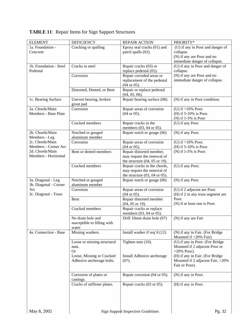
May 8, 2002 Sign Support Inspection Guidelines Pg. 32
TABLE 11: Repair Items for Sign Support Structures
ELEMENT DEFICIENCY REPAIR ACTION PRIORITY*1a. Foundation -Concrete
Cracking or spalling Epoxy seal cracks (01) andpatch spalls (02).
(U) if any in Poor and danger ofcollapse.(N) if any are Poor and noimmediate danger of collapse.
Cracks in steel Repair cracks (03) orreplace pedestal (05).
Corrosion Repair corroded areas orreplacement of the pedestal(04 or 05).
1b. Foundation - SteelPedestal
Distorted, Dented, or Bent Repair or replace pedestal(04, 05, 06).
(U) if any in Poor and danger ofcollapse.(N) if any are Poor and noimmediate danger of collapse.
1c. Bearing Surface Uneven bearing, brokengrout pad
Repair bearing surface (08). (N) if any in Poor condition.
Corrosion Repair areas of corrosion(04 or 05).
(U) if >10% Poor.(H) if 5-10% is Poor.(N) if 1-5% is Poor
2a. Chords/MainMembers - Base Plate
Cracked members Repair cracks in themembers (03, 04 or 05).
(U) if any Poor
Notched or gougedaluminum member
Repair notch or gouge (06) (N) if any Poor.
Corrosion Repair areas of corrosion(04 or 05).
Bent or dented members Repair distorted member,may require the removal ofthe structure (04, 05 or 19).
(U) if >10% Poor.(H) if 5-10% is Poor.(N) if 1-5% is Poor.
2b. Chords/MainMembers - Leg2c. Chords/MainMembers - Corner Arc2d. Chords/MainMembers - Horizontal
Cracked members Repair cracks in the chords,may require the removal ofthe structure (03, 04 or 05).
(U) if any Poor.
Notched or gougedaluminum member
Repair notch or gouge (06) (N) if any Poor
Corrosion Repair areas of corrosion(04 or 05).
Bent Repair distorted member(04, 05 or 19).
Cracked members Repair cracks or replacemembers (03, 04 or 05).
(U) if 2 adjacent are Poor.(H) if 2 in any truss segment arePoor.(N) if at least one is Poor.
3a. Diagonal - Leg3b. Diagonal - CornerArc3c. Diagonal - Truss
No drain hole andsusceptible to filling withwater
Drill 10mm drain hole (07) (N) if any are Fair
Missing washers. Install washer if req’d (12) (N) if any in Fair. (For BridgeMounted if >20% Fair).
Loose or missing structuralnuts.OrLoose, Missing or CrackedAdhesive anchorage bolts.
Tighten nuts (10).
Install Adhesive anchorage(07).
(U) if any in Poor. (For BridgeMounted if 2 adjacent Poor or>20% Poor).(H) if any in Fair. (For BridgeMounted if 2 adjacent Fair, >20%Fair or Poor).
Corrosion of plates orcastings.
Repair corrosion (04 or 05). (N) if any in Poor.
4a. Connection - Base
Cracks of stiffener plates. Repair cracks (03 or 05). (H) if any in Poor.

May 8, 2002 Sign Support Inspection Guidelines Pg. 33
Cracks of base platescastings.
Repair cracks (03 or 04). (U) if any in Poor.
Missing washer Install washer if req’d (12). (N) if any in Fair.Loose, missing, cracked, orbroken nuts or bolts.
Replace (11) or tighten (10)the nut or bolt.
(U) if any in Poor.(H) if any in Fair.
End plates without propercontact
Repair connection plates(09).
(N) if any in Poor condition.
Corrosion of end plates Repair areas of corrosion(04 or 05).
(N) if any in Poor.
Corrosion of stiffener plates Repair areas of corrosion(04 or 05).
(H) if any in Poor.
4b. Connection - Leg4c. Connection - InLine Chord
Cracks in base plate orcastings.
Repair cracks in theconnection, may require theremoval of the structure (03,04, 05).
(U) if any in Poor
Missing washers. Install washers if req’d (12). (N) if >20% in Fair.Loose, missing, cracked orbroken clamps.
Tighten (13) or replace (14)clamps.
(U) if >10% or 2 adjacent arePoor.(H) if 5-10% are Poor.(N) if 0-5% are Poor or any Fair.
4d. Connection - Sign4e. Connection -Damping Assembly4f. Connection -Walkarm4g. Connection -Accessory
Embedded stud/boltcorroded, loose, or cracked.
Install new AdhesiveAnchorage bolt (07).
(U) if >10% or 2 adjacent arePoor.(H) if 5-10% are Poor.(N) if 0-5% are Poor or any Fair.
Any loose, bent, orotherwise dangerous signthat is easy to repair.
Make minor repair to sign(15).
(N) if >20% in Fair or any inPoor.
5a. Attachment - Sign
Any loose, severely bent,cracked or otherwisedangerous sign that is morecomplex to repair.
Make major repair to sign asrequired (16).
(U) if Poor and immediate dangerof collapse.(N) if Poor and no danger ofcollapse.
5b. Attachment - Skin Cracked welds Repair cracked weld (03). (N) if any Poor.Any loose, bent, orotherwise dangerousattachment that is easy torepair.
Make minor repair to theattachment (15).
(N) if >20% in Fair or any inPoor.
5c. Attachment –Damping Assembly5d. Attachment –Walkway Arm5e. Attachment –Walkway5f. Attachment –Handrail5g. Attachment - OtherAccessory
Any loose, severely bent,cracked or otherwisedangerous attachment that ismore complex to repair.
Make major repair to theattachment as required (16).
(U) if Poor and immediate dangerof collapse.(N) if Poor and no danger ofcollapse.
6a. Coating –Chord/Main Member6b. Coating – Diagonal
Peeling, flaking or crackingof coating.
Apply overall coating (18). (N) if >75% Poor.
6c.Coating –Connections
Peeling, flaking or crackingof coating.
Apply localized coating(17).
(N) if >25% Poor.
* - For amounts less than shown in the Tables, or for elements in other Condition States, no repair isrequired. The inspector may use judgement to determine a different priority, or to determine a need,based on the observed conditions in the field.
(The repair code is given in brackets.)(U) - Urgent repair is required within 1 month.(H) - High priority repair is required within 1 year.(N) - Normal priority repair is required within 3 years.
May 8, 2002 Sign Support Inspection Guidelines Pg. 34
VII. STRUCTURE RATING (to be fully implemented at a later date)
The structure rating methods presented in this part of the guidelines are a means of categorizing thestructures’ overall condition. This part is not required in any way to perform an inspection of the structure orto record the inspection information.
Using the inspection information, some simple rules will be applied to obtain an overall structure ratingnumber and an overall structure condition. The ratings and conditions can be used to rank the sign supportstructures in an approximate order reflecting the severity of the defects and the effect on the overallperformance of the structure. When decisions are to be made on programming certain structures for repair,the structure ranking can be used as a guide. However, the region can create a program priority listing basedon this and/or any other information that they deem significant.
In determining the importance of various elements on the performance of the structure, the overall effect ofthe element on the strength and stability of the structure has been estimated. Elements that primarily effectthe durability of the structure are deemed less important when deriving the structure rating. Table 12 providesinformation on the assumed importance of the various elements in the overall sign support structure.
The actual structure rating is derived by combining the element conditions and applying weighting factorsaccording to the importance of the element on the overall structure. The method of obtaining the rating isdetailed in Table 13.
The structure rating and structure conditions have not been finalized at this time. As inspection data becomesavailable, the formulae for determining structure rating and structure condition will be improved.

May 8, 2002 Sign Support Inspection Guidelines Pg. 35
TABLE 12: Structure Rating: Importance of Elements
The overall condition of the structure is effected by the elements as described below.
ElementGroup
Element Name Importance* Comments
1a. Concrete SomewhatImportant
Deterioration of the Pedestal is not usually a commonor severe problem.
1b. Steel Pedestal Important The steel pedestal is somewhat over-designedcompared to the rest of the structure, however, it is asingle load path element.
1c.
Foundation
Bearing Surface Important Deterioration of the bearing surface can place higherthan expected load on the anchor bolts or legs. It has alarge effect on fatigue loading and ultimate strength ofthe structure.
2a. Base Plate2b. Leg2c. Corner Arc2d.
Chord/MainMember
Horizontal
Very Important(SomewhatImportant forBridge MountedSigns)
The chords are the main load carrying members of thetruss, although some minor load re-distribution ispossible through the truss-work.(For bridge mounted signs, the chords carry little axialload but still are the main attachment points.
3a. Leg3b. Corner Arc3c.
Diagonal
Truss
Important The diagonal members are significant for resistingwind and truck gust loads. Load re-distribution ispossible due to the great number of diagonals andthrough the chords in bending.
4a. Base Very Important This connection is responsible for supporting the entirestructure.
4b. Leg4c. In Line Chord
Very Important Connection of the chords is required to maintain theintegrity of the main load carrying members.
4d. Sign4e. Damping Assembly4f. Walkway Arm4g.
Connection
Accessory
Important Any faults could lead to unexpected collapse of theelement, with possible injury to traffic or maintenancestaff.
5a. Sign SomewhatImportant
Any faults do not lead to a sudden collapse of thestructure or of the element, and typically show evidenceof distress prior to failure of the element.
5b. Skin MinorImportance
Any faults do not have a possibility of collapse of thestructure or of the element
5c. Damping Assembly5d. Walkway Arm5e. Walkway5f. Handrail5g.
Attachment
Other Accessory
SomewhatImportant
Any faults do not lead to a sudden collapse of thestructure or of the element, and typically show evidenceof distress prior to failure of the element.
6a. Chords/Main Member6b. Diagonals6c.
Coating
Connections
MinorImportance
Any faults do not have a possibility of collapse of thestructure or of the element
* - The importance is based on the expected behaviour of the structures. If the inspector determines thatany component is in extremely poor condition, the urgent repair option can be chosen for the element.

May 8, 2002 Sign Support Inspection Guidelines Pg. 36
TABLE 13: Structure Rating: Weighting of Elements
The overall rating of the structure is determined as described below.
Rating ( )( ) ( )( )[ ]∑ +−=
PFFSSR IMP 0.55.0100
OverallCondition
Excellent - if SSR >95Good - if SSR >75Fair - if SSR > 40Poor - if SSR < 40
Where: SSR = Sign Structure Rating.
FIMP = Importance Factor = 10.0 for Very Important2.0 for Important0.4 for Somewhat Important0.1 for Minor Importance
F = Number of elements in Fair condition stateP = Number of elements in Poor condition state

May 8, 2002 Sign Support Inspection Guidelines Pg. 37
VII. REFERENCES
The following references have been used in the preparation of these guidelines:
MTO - Ontario Structure Inspection Manual (OSIM).MTO - Safety Practices for Structure Inspections.Overhead Sign Structure Inventory and Inspection Manual – State of New York DOT.Statewide Inspection of Traffic Structures – State of Virginia DOT.MTO - Sign Support Manual.

May 8, 2002 Sign Support Inspection Guidelines Pg. 38
APPENDIX A:
Maintenance Procedures for Sign Support Structures
(The number in brackets is the maintenance need number found on the inspection form)
Clean Debris (01).
1. Debris against the structure will trap water and promote corrosion.2. The debris should be removed and the area washed of any corrosive salts.
Regrade (02).
1. If the soil is encroaching on the foundation base, this will trap water and lead to premature corrosion.2. The soil should be removed and regrading shall be done to prevent the soil from falling back into this
area.
Remove Clamps Causing Galvanic Corrosion (03).
1. Clamps of dissimilar metal to the structure will lead to galvanic corrosion and section loss.2. Remove the clamps. If it is required to replace the clamps, they should be placed in a slightly
different location so that the area with section loss can be easily viewed.
Replace covers on Members (04).
1. If a cover is missing, corrosive salts and water can enter the tubes and lead to premature corrosion.2. A cover, made from the same material as the member, shall be attached to cover the hole.
Seal Leak (05)
1. If the enclosed CMS sign is leaking, some components may become damaged.2. Seal the leak with caulking, silicone, or another appropriate sealant.

May 8, 2002 Sign Support Inspection Guidelines Pg. 39
APPENDIX B
Repair Procedures for Sign Support Structures
(The number in brackets is the repair need number found on the inspection form)
The repair procedures listed below are general repair strategies that are applicable for most commonsituations. The engineer may consider a different repair depending on the specific conditions that are present.
Repair Procedure for Concrete Foundation: Crack (01) or Spall (02) repair
1. All loose and delaminated concrete shall be removed. If there is any danger of stability of thestructure, the structure shall be removed during the repair material.
2. Concrete shall be patched with an approved repair.3. Excessive cracks shall be repaired by epoxy injection.
Repair Procedure for Cracks in Members: Re-weld (03), Lap (04) or Replace (05) member
1. Where the termination of the cracks cannot be determined, the area should be tested, either by LiquidPenetrant Testing (LPT) or Ultrasonic Testing (UT), to identify the extent of the cracking.
2. In determining a repair strategy for the structure, the condition of the entire component, and of all thecomponents, should be considered. If various defects occur and are widespread, it may be costadvantageous to replace the entire segment, or replace the entire sign support.
3. For transverse cracks in the parent material or in welds of diagonals;a) Where there is no or minimal separation of the crack (less than 1 or 2mm), the crack shall be
removed (by grinding) and the area re-welded.b) Where there is a larger separation of the crack, the damaged member shall be removed and
replaced.4. For transverse cracks in the parent material or in welds of chords;
a) Where there is no or minimal separation of the crack, the crack shall be removed and the area re-welded.
b) Where there is a larger separation of the crack, or where the crack extends greater than 20% ofthe circumference, the damaged member shall be removed and replaced or covered with a lapsplice plate.
5. For longitudinal cracks in parent material;a) Where there is no or minimal separation of the crack, the crack shall be removed and the area re-
welded.b) Where there is a larger separation of the crack, the damaged member shall be removed and
replaced or covered with a lap splice plate.6. No or minimal separation is defined as a gap that can easily be closed by temporary clamping, or
approximately 2 mm.7. Crack removal, where required, shall be complete crack removal and be done by gouging, shipping,
machining or grinding.8. For all welding, the groove shall then be properly prepared to meet the joint and geometry
requirement specified in the corresponding Welding Procedure Data Sheet (WPDS), specificallyprepared by the welding engineer to meet by the Canadian Welding Bureau (CWB) standards for therepair of cracks in aluminum or steel sections.
9. For all field repairs, where the length of the crack is greater than 20% of the circumference, the areashould be stabilized with temporary bracings and clamps to ensure satisfactory fit-up during possiblein-service vibrations.

May 8, 2002 Sign Support Inspection Guidelines Pg. 40
10. If satisfactory fit-up of a diagonal cannot be achieved during preparation, the member should bereplaced. If satisfactory fit-up of a chord or, a plate or stiffener attached to the chord, cannot beachieved during preparation, the repair will require a suitable back up bar, as specified in thecorresponding Welding Procedure Data Sheet (WPDS).
11. For all welding, the heat due to welding can have an effect on the load carrying capacity of themember. The heat shall be carefully controlled to ensure that there is no adverse stress redistribution.
12. Where members are to be replaced, the new member shall be of corresponding material and physicalproperties. Where lap plates are used for aluminum members, the ends of the plate shall be tapered tominimize the length of weld transverse to the member.
13. All groove welds shall be ground flush.14. If the source of the cracking is due to the accumulation of water, drain holes should be drilled. This
may occur on some diagonals and be evident by splitting of the tube. Also, cracking at theconnection of an aluminum diagonal to an aluminum casting is often caused by water filling thecasting, causing corrosion that pushes apart the tines of the casting, and initiates the cracking. In thiscase, a drain hole should be drilled in the casting.
15. After welding, the members shall be coated similar to the existing coating.
Repair Procedure for Bent, Dented or Distorted Members: Lap (04), Replace (05) or Heat Straightenmember (08)
1. Minor dents, bends or distortions that fall into the fair condition state do not require repair.2. In determining a repair strategy for the structure, the condition of the entire component, and of all the
components, should be considered. If various defects occur and are widespread, it may be costadvantageous to replace the entire segment, or replace the entire sign support
3. For all sections;a) Bent or distorted aluminum members shall not be straightened by heat or mechanical means.b) Localized dents or bends on aluminum, not exceeding 50% of the circumference in width, the
area shall be covered with a lap plate. Bends and dents without sharp kinks on steel shall berepaired by heating and straightening or by lap plate.
c) All severely bent or distorted members, including those with sharp kinks, as well as larger dents,the damaged sections shall be removed completely, at the connecting fillet welds, and replaced.
4. Welding, if required, shall be as described in the notes 8-12 above.5. Temporary bracing may be required if straightening members by heating.6. After repair, the members shall be coated similar to the existing coating.
Repair of Notched or Gouged Members: Weld Gouge (06)
Notches or gouges can occur from impact, or from improper fabrication, transportation or erection of the signsupport structure. These notches provide a location for stress raisers and thus are poor for the fatigueperformance of the structure.
1. Notches in Fair Condition (less than 3mm in depth for aluminium and all notches in steel) typicallydo not require repair. Some grinding may be advisable if areas are very sharp.
2. All notches in aluminium requiring repair (the ones in Poor Condition) shall be repaired by grindingand welding. The notch or gouge shall be ground to a profile and welded as shown on the applicableWPDS. After welding, the weld shall be ground flush.
3. After repair, the members shall be coated similar to the existing coating.

May 8, 2002 Sign Support Inspection Guidelines Pg. 41
Repair Procedure for Corroded Members: Lap (04) or Replace (05) member
1. Only areas of severe corrosion require repair. Minor or moderate corrosion should have the surfacecleaned, to verify the degree of section loss, and re-coated with any further corrosion to be monitored.
2. All areas that are to be repaired shall be cleaned to determine the extent of the corrosion.3. In determining a repair strategy for the structure, the condition of the entire component, and of all the
components, should be considered. If various defects occur and are widespread, it may be costadvantageous to replace the entire segment, or replace the entire sign support
4. For all sections;a) For localized severe corrosion, extending less than 20% of the circumference for diagonals or
40% of the circumference for chords, the area shall be covered with a lap plate.b) For more general severe corrosion, the damaged member shall be removed completely, at the
connecting fillet welds, and replaced.5. Welding, if required, shall be as described in the notes 8-12 above.6. After repair, the members shall be coated similar to the existing coating.
Repair procedure for lack of Drain Holes in Members susceptible to filling with water (07).
1. The crew should verify the safety of the walkway prior to using it. The repair work may need to bedone by bucket truck for structures with unsafe or non-existent walkways.
2. Only those members that are closed ended at the bottom and either open-ended or closed ended withdrain (or vent) holes at the top will require drain holes. If no drain (or vent) holes are visible at thetop or bottom of the member, it is probable that internal venting exists, thus the addition of drainholes are not required.
3. Drain holes are to be 10mm in diameter and located on the lower face, at the bottom end of themember.
Repair Procedure for Connection of Bridge Mounted Signs to Structure: Install Adhesive Anchoragebolt (09).
1. Cut off or remove the bolt.2. Either reuse existing hole, or drill new hole through plate and into bridge.3. Ensuring full contact of plate, install new Adhesive Anchorage type bolt. Size of the new bolt should
match the existing, but should not be less than 15mm.4. Sign structure may have to be relocated.
Repair Procedure for Bearing Surface (10).
1. The leg of the sign support shall have a uniform bearing on the foundation.2. All poor areas, as well as areas determined by the engineer, should be repaired.3. If there is poor contact between the leg and the foundation, including deteriorating grout pads, the
area shall be cleaned and an epoxy or cement grout pad (depending on the thickness) used to level thesurface. If a rubber gasket is present, the grout shall not be placed on top of the gasket. Dependingon the condition, it may be necessary to remove or temporarily support the structure while the repairis being done.
May 8, 2002 Sign Support Inspection Guidelines Pg. 42
Repair Procedure for Misaligned Plate Connections (11).
1. All plate-to-plate connections should provide close to uniform bearing. This reduces fatigue loadingand improved the performance of the bolts.
2. All repairs shall be as directed by the engineer, the following are some suggested options:a) The plates can be brought into contact by tightening the bolts. If the bolts are seized, they can be
removed (one at a time) and replaced with a new bolt.b) A carefully measured and manufactured bevel plate can be placed in the connection to provide
proper bearing. This would require the removal or temporary support of the structure.c) The stiffener plates can be cut, the plates can then be brought into contact by tightening the bolts,
and the stiffeners then re-welded.3. In all cases, the area between the plates should be cleaned to allow for proper bearing of the two
surfaces after the repair is completed.
Replacing (13) or Tightening (12) Bolts for Chord, Leg or Base Connections
1. The crew should verify the safety of the walkway prior to using it. The repair work may need to bedone by bucket truck for structures with unsafe or non-existent walkways. The weight of the crew, orthe wind gusts from passing trucks, will not have an impact on the repair.
2. Each bolt in a connection should be removed and replaced prior to removal of subsequent bolts in theconnection.
3. The bolts for connecting members should be tightened using the turn-of-nut method.
Adding Washer to Bolts (14).
1. Washers should only be placed in locations where there is doubt concerning the bearing of the nut.2. The nut shall be removed, and a proper washer placed. It should be noted that often the bolts are in a
rusted or seized condition and that removal may lead to damage of the bolt. When removing nuts, alubricant should be used and replacement bolts should always be on hand.
3. Extreme caution should be used when trying to add a washer under a stud or bolt that is anchored inconcrete. In these cases, if the bolt is damaged during removal of the nut, the replacement bolt willbe very difficult to install. Attempts to add washers in these circumstances should only be done whenabsolutely necessary.
Replacing (16) and Tightening (15) Clamps on Signs, Walkway Arms or Other Attachments
1. The crew should verify the safety of the walkway prior to using it. The repair work may need to bedone by bucket truck for structures with unsafe or non-existent walkways.
2. Each clamp should be removed and replaced prior to removal of subsequent clamps.3. The removal should begin with the clamps that are in the worst condition.4. Caution should be exercised to not over-tighten the clamps.5. When tightening clamps, additional clamps should be available in case the threads become damaged.
May 8, 2002 Sign Support Inspection Guidelines Pg. 43
Minor Repair of Sign or Other Attachment (17)
1. The crew should verify the safety of the walkway prior to using it.2. This item includes items that are easy to perform regardless of whether it has a large or small effect
on the overall strength or stability of the component.3. This includes tightening bolts or clips within the sign panel or other attachment or other defective
areas that can easily be corrected.
Major Repair of Sign or Other Attachment (18).
1. The crew should verify the safety of the walkway prior to using it. The repair work may need to bedone by bucket truck for structures with unsafe or non-existent walkways.
2. This item include larger repairs that are more complex, more time consuming and also for repairs thatrequire the sign panel or other attachment to be removed and repaired in a shop environment.
3. If the sign or other attachment can be repaired in place, the necessary repairs shall be done asrequired.
4. If the repairs are deemed to be excessive, the sign or other attachment shall be removed and eitherfixed in a shop environment or replaced. The sign or other attachment shall be temporarily supportedprior to removal of the clamps that hold it on.
Applying New Coating: Loacalized (19) or Overall (20)
1. The purpose of the coating is for aesthetics and for protection the members.2. Applying a new coating the structure is quite expensive and usually involves removing the structure
and performing the work in a shop environment. This should be considered before recommendingthat a new coating be applied.
3. The application of a new coating in localized areas is often a preferred option. Usually the poor areasare confined to the areas around the base plate, and possibly other connection areas.
4. The areas to receive a new coating should be cleaned by blast cleaning or wire brush. An approvedcoating should be applied.

May 8, 2002 Sign Support Inspection Guidelines Pg. 44
APPENDIX C
Sign Support Inspection Guidelines MTO Site Number:Inspection Form (Inventory)
Inventory Data:
Structure Name
Location: Comments
Direction: Core/Collector/Ramp
MTO Region Main Highway
MTO District Owner
Old County AADT
Old Site No. Inspection Route Sequence
Manufacturer Vertical Clearance (m)
Latitude Longitude
Sign Support Type Sign Type
Left Footing Type Right Footing Type
Sign Height (m) Length (m) Colour Overlay Contents
A
B
C
Total Sign Area (m2) Maximum Allowable Area (m2) Span (m)
Attachments
Historical Data:
Year Built Contract Number When Built
Latest Biennial Inspection Latest Specialized Inspection
Latest Structure Rating: Latest Structure Condition:
Rehab. History:(Date/description)
Regional Priority Number Programmed Work Year
Nature of Program Work:
May 8, 2002 Sign Support Inspection Guidelines Pg. 45
APPENDIX D
Sign Support Inspection Guidelines MTO Site Number:Inspection Form (General Inspection)
Additional Investigations Required: PriorityNone Normal Urgent
Detailed Weld Inspection:
Structure Evaluation:
Other Evaluation:
Special Notes/General Comments:
Next Biennial Inspection:
Field Inspection Information:
Date of Inspection:
Inspector:
Others in Party:
Equipment Used:
Weather:
Temperature:
Suspected Performance Deficiencies01 Tilted/Shifted Foundation 04 Suspected Deficient Size Of
Anchorage07 Other
02 Deficiency In Material ofIndeterminate Magnitude, Do ANDT (Non Destructive Test)
05 Suspected Deficiency in StructuralCapacity
03 Galvanic Corrosion 06 Suspected Lack Of Stud Embedment
Maintenance Needs01 Clean Debris 04 Replace Cover 07 Other02 Regrade Soil 05 Seal Leak03 Remove Clamps 06 Minor Maintenance of Sign or Other
Attachment
Repair Needs01 Epoxy Seal Crack In Concrete 08 Heat Straighten member 15 Tighten Clamp02 Patch Spalled Concrete 09 Repair Adhesive Anchorage Bolt 16 Replace Clamp03 Re-weld member 10 Repair Bearing Surface 17 Minor Repair Sign Or Attachment04 Add lap plate 11 Repair Misaligned Connection Plate 18 Larger Repair Sign Or Attachment05 Replace member 12 Tighten Bolts 19 Apply Localized Coating06 Repair gouge in member 13 Replace Bolts 20 Apply Overall Coating07 Drill Drain Hole 14 Add Washer To Bolts 21 Other
May 8, 2002 Sign Support Inspection Guidelines Pg. 46
Sign Support Inspection Guidelines MTO Site Number:Inspection Form (Elements)
Group: Name: Tot. Quantity: Not Insp’d ÿLocation: Material UrgencyMaint. Rehab. Rehab.
Units Exc/Good
Fair Poor PerformDefic. # Code # Code # Code
ConditionData:
each
None3 year1yearNow
Comments:
Group: Name: Tot. Quantity: Not Insp’d ÿLocation: Material UrgencyMaint. Rehab. Rehab.
Units Exc/Good
Fair Poor PerformDefic. # Code # Code # Code
ConditionData:
each
None3 year1yearNow
Comments:
Group: Name: Tot. Quantity: Not Insp’d ÿLocation: Material UrgencyMaint. Rehab. Rehab.
Units Exc/Good
Fair Poor PerformDefic. # Code # Code # Code
ConditionData:
each
None3 year1yearNow
Comments:
Group: Name: Tot. Quantity: Not Insp’d ÿLocation: Material UrgencyMaint. Rehab. Rehab.
Units Exc/Good
Fair Poor PerformDefic. # Code # Code # Code
ConditionData:
each
None3 year1yearNow
Comments:
Group: Name: Tot. Quantity: Not Insp’d ÿLocation: Material UrgencyMaint. Rehab. Rehab.
Units Exc/Good
Fair Poor PerformDefic. # Code # Code # Code
ConditionData:
each
None3 year1yearNow
Comments:

May 8, 2002 Sign Support Inspection Guidelines Pg. 47
Sign Support Inspection Guidelines MTO Site Number:Inspection Form (Elements) [Alternate Form]
Maintenance Rehab. Rehab. Comments UrgencyGroup Name Loc’n Mat’l Qty Not
InspUnit Exc/
GoodFair Poor Perform
Defic. # Code # Code # Code
1a Concrete Each
1b Steel Pedestal Each
1c Brg. Surface Each
1d
Foundation
Anch. Bolts Each
2a Base Plate Each
2b Leg Each
2c Corner Arc Each
2d
Chord/MainMembers
Horizontal Each
3a Leg Each
3b Corner Arc Each
3c
Diagonal
Truss Each
4a Base Each
4b Leg Each
4c In Line Chord Each
4d Sign Each
4e Damp Assemb Each
4f Walkway Arm Each
4g
Connection
Accessory Each
5a Sign Each
5b Skin Each
5c Damp Assemb Each
5d Walkway Arm Each
5e Walkway Each
5f Handrail Each
5g
Attachment
Other Access. Each
6a Chords Each
6b Diagonals Each
6c
Coating
Connections Each

May 8, 2002 Sign Support Inspection Guidelines Pg. 48
APPENDIX E: 1999 Bridge Office Memo for Aluminum Tapered LegSign Supports
MEMO
To: Regional Managers of Engineering February 12, 1999 Heads, Regional Structural Sections
Re: Type 1 Overhead Sign Support Structures
Please find attached the Evaluation Report on Structural Adequacy of Type 1 OverheadSign Support Structures. The evaluation reveals that the Type 1 Sign Support Structuresare structurally deficient if they carry more than 240 square feet of sign areas. There arealso problems related to construction tolerance of the base anchorage, corrosion distressand fatigue cracking of welds. Many components are subjected to excessive fatiguestress ranges and may therefore be approaching their fatigue life.
The report has recommended the following immediate actions in order to ensure safety:
i. An inventory survey and a detailed one-time inspection of all Type 1 sign supportstructures should be performed immediately according to the following priority:• Structures carrying changeable message signs• Structures carrying sign area > 240 square feet• All other structures
All structures should be identified by a reference site number with proper record of thesignage areas. The detailed inspection should be carried out by qualified structuralinspectors and should be sufficiently thorough to cover each structure in its entirety, withparticular attention to the following critical areas:• Connection of diagonal members to splice of chords• Welding of legs to base casting• As-built distance between base supports• Other diagonal members welded connections to chords• Attachment of any dissimilar metal like grounding cables that may cause galvanic
corrosionii. Carry out structural evaluations for structures carrying changeable message signs.iii. For structures with observed defects, including support mis-alignment, the following
actions can be taken:• Replace immediately; or• Carry out temporary repair ( if economically feasible ) and replace within 5 years if
the sign area is < 240 square feet; otherwise, replace within 3 years.• If support mis-alignment is the only observed defect, rectify the defect if it is
economically feasible, otherwise, replace within 3 years.iv. Plan for replacement of any other structures carrying sign area > 240 square feet within
3 years.v. Carry out biennial inspection on all Type 1 structures by qualified structural inspectors.
District inspection currently carried out on an annual basis should continue.

May 8, 2002 Sign Support Inspection Guidelines Pg. 49
Since there may be Type 1 sign support structures that have suffered critical distresses and areunsafe to the travelling public, prompt actions would have to be taken to either repair or replacethem. Hence, the inventory survey and the detailed inspection should be expedited. Werecommend that the survey and detailed inspection be completed in six months. The detailedinspection should be programmed and co-ordinated by the Regional Structural Sections; BridgeOffice would provide technical support to the Regions to analyse the inspection data and todetermine structures that would require temporary repairs. Bridge Office is currently developinga temporary repair scheme specifically for the diagonal connection to the chord splices; otherrepair schemes may have to be developed in due course for other defects. Bridge Office is alsodeveloping a set of inspection guidelines for the biennial inspection to be carried out by theRegional Structural Sections and for the regular annual inspection carried out by the Districts;some interim guidelines could also be provided for the initial detailed inspection if it is requiredby the Regions.
In view of the many defects and deficiencies of this type of sign support structure, and thepotential high cost of repair and on-going maintenance, it would be prudent to program for theirreplacement with new standard types of sign support structures, particularly when there aremajor highway improvement works in the vicinity.
Original signed by:
Bala TharmabalaManager, Bridge Office
cc. Heads, Bridge Office

May 8, 2002 Sign Support Inspection Guidelines Pg. 50
APPENDIX F: PHOTOGRAPHS
Included are pictures of the various types of sign supports, as well as pictures of the element types toshow which components are included with which elements and to show some common material defects.
The figure number relates to the element number found in other areas of the guidelines. When the Figurenumber is 0, this relates to an overall photograph of the sign support structure. When the Figure numberis from 1 to 6, this relates to the element numbers found in the guidelines. The digits after the decimal aresimply the photograph numbers within each element number.
A detailed description of what components are included with each element is found in Part V, Section D,sub-section 1 to 6.
Figure 0.1 Aluminum Tapered Leg Sign Support (ATL)

May 8, 2002 Sign Support Inspection Guidelines Pg. 51
Figure 0.2 Aluminum Circular Leg Sign Support (ACL): Note circular legs
Figure 0.3 Aluminum Rectangular Leg Sign Support (ARL): Note Rectangular Legs.

May 8, 2002 Sign Support Inspection Guidelines Pg. 52
Figure 0.4 Changeable Message Sign Support (CMS)
Figure 0.5 Tri-Chord Sign Support (TC)

May 8, 2002 Sign Support Inspection Guidelines Pg. 53
Figure 0.6 Cantilever (C) Sign Support
Figure 0.7 Mono-Tube Sign Support (MT)

May 8, 2002 Sign Support Inspection Guidelines Pg. 54
Figure 0.8 Bridge Mounted Sign Support, (BM2) (Connected at 2 points, nowalkway)
Figure 0.9 Bridge Mounted Sign Support, (BM2) (Connected at 2 points – soffitand fascia, with walkway)
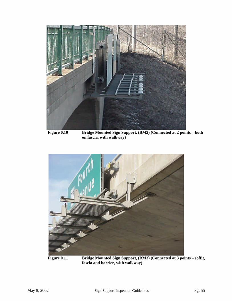
May 8, 2002 Sign Support Inspection Guidelines Pg. 55
Figure 0.10 Bridge Mounted Sign Support, (BM2) (Connected at 2 points – bothon fascia, with walkway)
Figure 0.11 Bridge Mounted Sign Support, (BM3) (Connected at 3 points – soffit,fascia and barrier, with walkway)

May 8, 2002 Sign Support Inspection Guidelines Pg. 56
Figure 0.12 Bridge Mounted Sign Support, BM3) (Connected at 3 points – soffit,2 on fascia, with walkway)
Figure 0.13 Bridge Mounted Sign Support, (BM2S) (Connected at 2 points –soffit and fascia, with walkway and spacer truss behind sign).
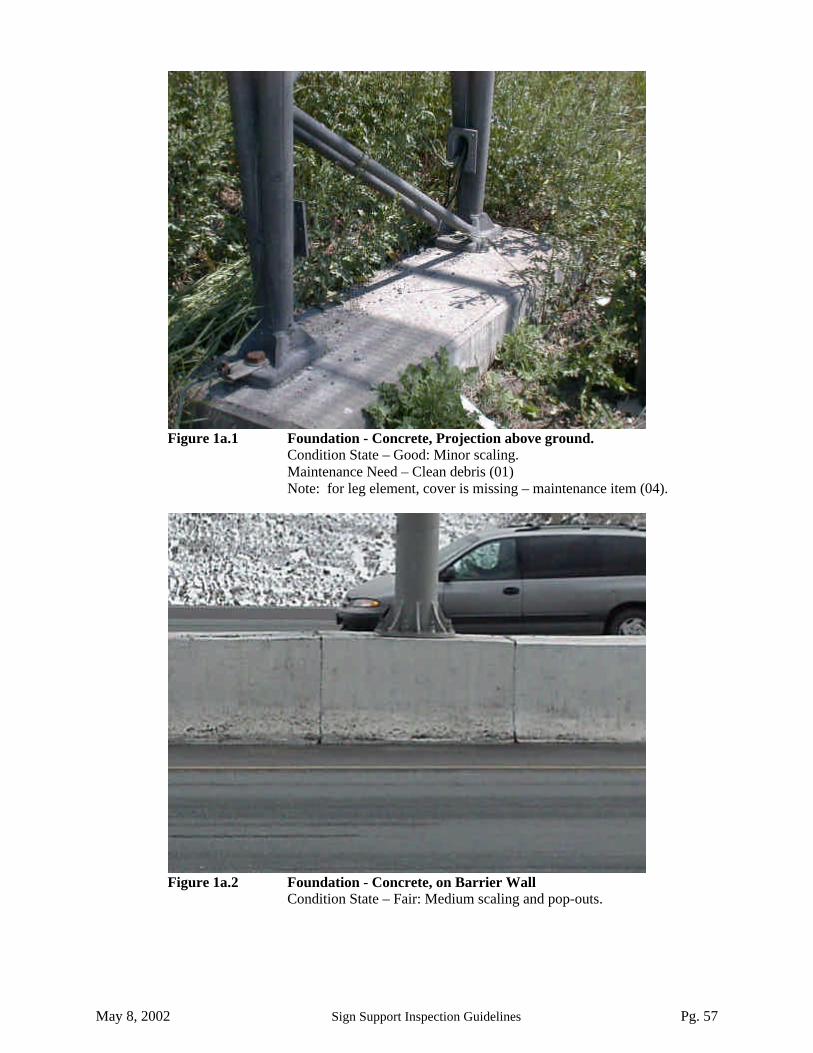
May 8, 2002 Sign Support Inspection Guidelines Pg. 57
Figure 1a.1 Foundation - Concrete, Projection above ground.Condition State – Good: Minor scaling.Maintenance Need – Clean debris (01)Note: for leg element, cover is missing – maintenance item (04).
Figure 1a.2 Foundation - Concrete, on Barrier WallCondition State – Fair: Medium scaling and pop-outs.

May 8, 2002 Sign Support Inspection Guidelines Pg. 58
Figure 1a.3 Foundation - Concrete, Bridge Mounted (ATL) Sign SupportCondition State – Fair: Medium scaling.Maintenance Need – clean debris (01).
Figure 1b.1 Foundation - Steel Pedestal Under ATL Sign SupportCondition State – Good: Light corrosion with no section loss.Maintenance Need – clean debris (01).
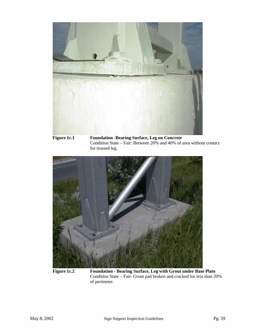
May 8, 2002 Sign Support Inspection Guidelines Pg. 59
Figure 1c.1 Foundation -Bearing Surface, Leg on ConcreteCondition State – Fair: Between 20% and 40% of area without contactfor trussed leg.
Figure 1c.2 Foundation - Bearing Surface, Leg with Grout under Base PlateCondition State – Fair: Grout pad broken and cracked for less than 20%of perimeter.

May 8, 2002 Sign Support Inspection Guidelines Pg. 60
Figure 1c.3 Foundation - Bearing Surface, Leg with Rubber PadCondition State – Good: Rubber pad in contact over most of the area.
Figure 2a.1 Chord - Base Plate , Aluminum Casting of ATL Sign SupportCondition State – Fair: Local corrosion with less than 10% section loss.

May 8, 2002 Sign Support Inspection Guidelines Pg. 61
Figure 2b.1 Chords - Leg, ATL Type Sign SupportCondition State – Poor: Local notch (gouge) in aluminum of depth
greater than 3mm.Rehablilitation Need – Repair notch or gouge (06).
Figure 2b.2 Chords - Leg, ACL Sign SupportCondition State – Good: Minor corrosion with no section loss.
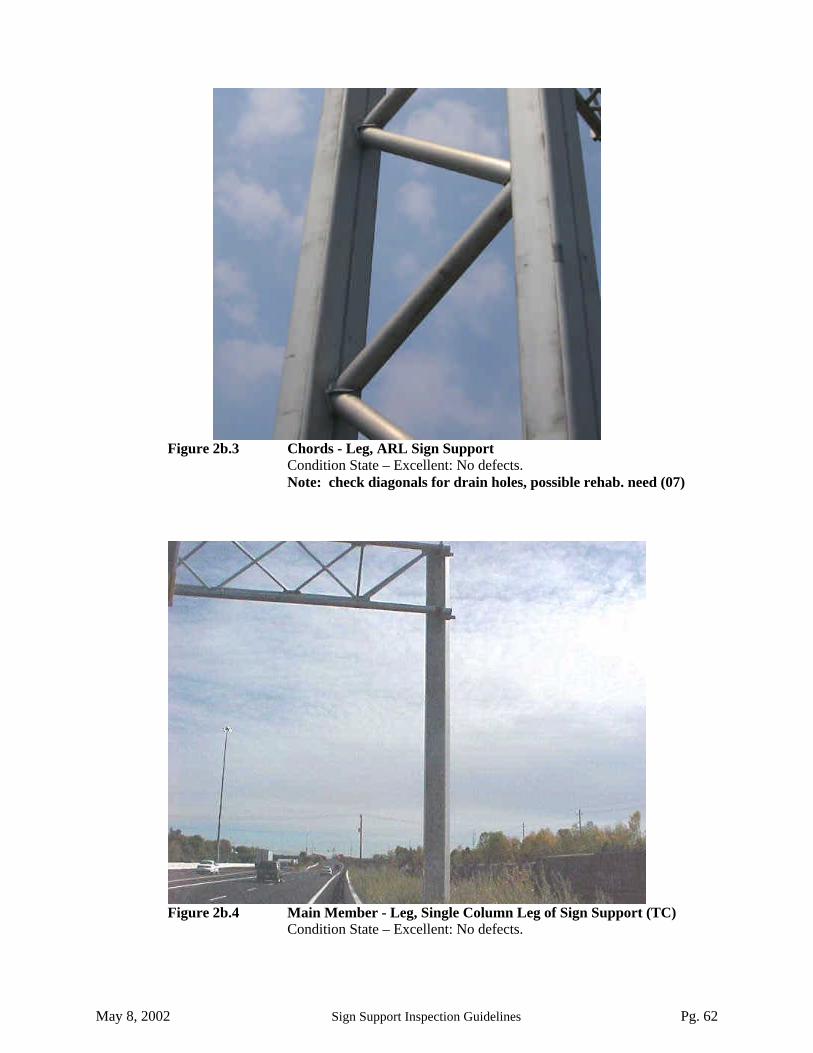
May 8, 2002 Sign Support Inspection Guidelines Pg. 62
Figure 2b.3 Chords - Leg, ARL Sign SupportCondition State – Excellent: No defects.Note: check diagonals for drain holes, possible rehab. need (07)
Figure 2b.4 Main Member - Leg, Single Column Leg of Sign Support (TC)Condition State – Excellent: No defects.

May 8, 2002 Sign Support Inspection Guidelines Pg. 63
Figure 2c.1 Chords of Corner Arc, ATL Sign SupportCondition State – Excellent: No defects.
Figure 2d.1 Chords – Horizontal, Aluminum Sign SupportCondition State – Good: Note that shop splice is included with chord andnot with connection. Minor corrosion with no section loss.Note: replace cover on conduit – maintenance item (04).

May 8, 2002 Sign Support Inspection Guidelines Pg. 64
Figure 2d.2 Chords – Horizontal, CMS Type Sign SupportCondition State – Excellent: No defects.
Figure 2d.3 Chords – Horizontal, Tri-Chord Sign SupportCondition State – Excellent: No corrosion (coating has runs).

May 8, 2002 Sign Support Inspection Guidelines Pg. 65
Figure 2d.4 Chord - Horizontal, Cantilever Sign SupportCondition State – Excellent: No defects.
Figure 3a.1 Diagonals – Leg, ATL Sign SupportCondition State – Fair: Notch (gouge) less than 3mm depth.Repair Need – Repair not required according to guidelines (06).

May 8, 2002 Sign Support Inspection Guidelines Pg. 66
Figure 3a.2 Diagonals – Leg, ARL new Sign SupportCondition State – Poor: Underside of diagonal member is cracked.Repair Need – Repair crack in Diagonal (03).
Figure 3b.1 Diagonals – Corner Arc, ATL Sign SupportCondition State – Poor: Crack at weld.Repair Need – Repair crack in diagonal at weld (03).

May 8, 2002 Sign Support Inspection Guidelines Pg. 67
Figure 3c.1 Diagonals –Truss, ATL SupportCondition State – Poor: Diagonal member bent (dented) over half the
circumference.Repair Need – replace member (05).
Figure 3c.2 Diagonals –Truss, CMS Type Sign SupportCondition State – Excellent: (note that the sloping chord and the twodiagonals are shown). No defects in the diagonals.

May 8, 2002 Sign Support Inspection Guidelines Pg. 68
Figure 4a.1 Connection - Base, Aluminum Base Plate of ARLCondition State – Good: All bolts tight, no corrosion of bolts.Note: square washers are not present, ensure round washers
provide adequate contact.
Figure 4a.2 Connection - Base, Steel Base Plate of Single Column LegCondition State – Excellent: All bolts tight, no corrosion.Note: For Concrete Foundation element, remove debris
(formwork) around base – maintenance item 01.

May 8, 2002 Sign Support Inspection Guidelines Pg. 69
Figure 4a.3 Connection - Base, Attachment of Bridge Mounted SignSupport to FasciaCondition State – Fair: Misaligned but tight bolts in 50% of bolts in connection.Also, medium corrosion of left side bolt.Note: Ensure bolts are tight by tapping with a hammer (if loose, condition is Poor).
Figure 4b.1 Connection –Leg, ACL Sign SupportCondition State – Excellent: No defect in weld connection of chord tocolumn.

May 8, 2002 Sign Support Inspection Guidelines Pg. 70
Figure 4b.2 Connection – Leg, ARL Sign SupportCondition State – Excellent: No defect in plate to column connection.
Figure 4b.3 Connection – Leg, Changeable Message SignCondition State – Excellent: All bolts tight, no defects in plates or rubberpad.

May 8, 2002 Sign Support Inspection Guidelines Pg. 71
Figure 4b.4 Connection – Leg, Tri-Chord Sign SupportCondition State – Good: no corrosion, bolts are tight, and bearing surface
(rubber gasket) slightly misaligned.
Figure 4b.5 Connection – Leg, Cantilever Sign SupportCondition State – Excellent. All bolts tight, full contact betweenconnecting plates, no defects on plates.
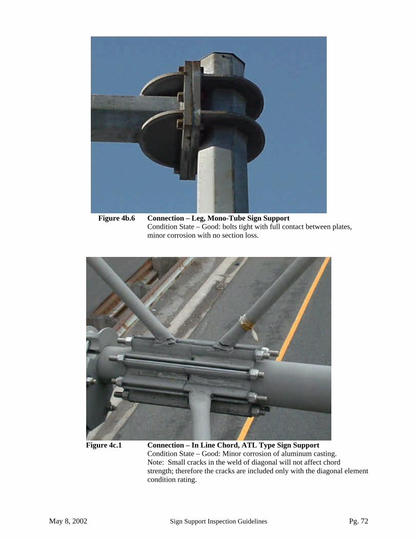
May 8, 2002 Sign Support Inspection Guidelines Pg. 72
Figure 4b.6 Connection – Leg, Mono-Tube Sign SupportCondition State – Good: bolts tight with full contact between plates,minor corrosion with no section loss.
Figure 4c.1 Connection – In Line Chord, ATL Type Sign SupportCondition State – Good: Minor corrosion of aluminum casting.Note: Small cracks in the weld of diagonal will not affect chordstrength; therefore the cracks are included only with the diagonal elementcondition rating.
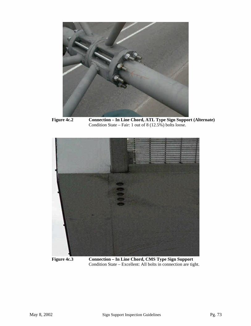
May 8, 2002 Sign Support Inspection Guidelines Pg. 73
Figure 4c.2 Connection – In Line Chord, ATL Type Sign Support (Alternate)Condition State – Fair: 1 out of 8 (12.5%) bolts loose.
Figure 4c.3 Connection – In Line Chord, CMS Type Sign SupportCondition State – Excellent: All bolts in connection are tight.

May 8, 2002 Sign Support Inspection Guidelines Pg. 74
Figure 4c.4 Connection – In Line Chord, Tri-Chord Sign SupportCondition State – Good. All bolts are tight with full contact betweenplates, minor corrosion with no section loss.
Figure 4c.5 Connection – In Line Chord, Mono-Tube Sign SupportCondition State – Good: All bolts tight, minor corrosion of plates with nosection loss.

May 8, 2002 Sign Support Inspection Guidelines Pg. 75
Figure 4d.1 Connection – Sign, ATL Type Sign SupportCondition State – Good: Cast aluminum clamp with minor corrosion andno section loss.
Figure 4d.2 Connection – Sign, Changeable Message Sign on ATL TypeCondition State – Good – Minor corrosion with no section loss.

May 8, 2002 Sign Support Inspection Guidelines Pg. 76
Figure 4d.3 Connection – Sign, Tri-Chord Sign SupportCondition State – Fair: Stainless steel U-bolt with no material defects butimproper thread projection.
Figure 4d.4 Connection – Sign, Bridge Mounted Sign SupportCondition State – Fair: Misaligned cast aluminum clamp.

May 8, 2002 Sign Support Inspection Guidelines Pg. 77
Figure 4e.1 Connection – Damping Assembly, Cantilever Sign SupportCondition State – Excellent: All bolts attaching support angles tobrackets on sign support are tight and no material defects.
Figure 4f.1 Connection – Walkway Arms, ATL Type Sign SupportCondition State – Poor: Crack in aluminum casting.Repair Need – Replace clamp (14).

May 8, 2002 Sign Support Inspection Guidelines Pg. 78
Figure 4f.2 Connection – Walkway Arms, Bridge Mounted Sign SupportCondition State – Good: Aluminum casting with minor corrosion, allbolts tight.
Figure 4g.1 Connection – Accessory, Traffic Signal Mounted to SignCondition State – Good: Accessory firmly attached, minor corrosion.

May 8, 2002 Sign Support Inspection Guidelines Pg. 79
Figure 4g.1 Connection – Accessory, Arrow Board to TrussCondition State – Poor: Accessory support is firmly attached, but signboard is missing
Figure 5a.1 Attachment – Sign, Sign Panel on ATL Type Sign SupportCondition State – Fair: Slight cracking and bending of one portion ofsign panel, no danger of sign panel falling off.

May 8, 2002 Sign Support Inspection Guidelines Pg. 80
Figure 5a.2 Attachment – Sign, old Changeable Message Sign Panel onAluminum SupportCondition State – Fair: Medium corrosion on components of sign panel.Suspected Performance Deficiency: Although bracket is attached firmlyto structure, the attachment of bracket to the remainder of sign ispossibly deficient. Possible deficiency in Structural Capacity (05).
Figure 5a.3 Attachment – Sign, Sign Panel on Tri-Chord Type SignCondition State – Excellent: Sign panel and support brackets with nomaterial defects.Note: for connection of sign panel, it appears the U-bolt at the upper leftis in fair condition – loose.

May 8, 2002 Sign Support Inspection Guidelines Pg. 81
Figure 5b.1 Attachment – Skin, Changeable Message SignCondition State – Excellent: No cracks in any welds and no corrosion ofaluminum skin.
Figure 5d.1 Attachment – Walkway Arms, Attached to ATL Type Sign SupportCondition State – Fair: Walkway arm slightly bent with minor corrosionand no cracking at joint.Note: If the arm is has cracks near the location of the bend then itsability to support load is suspect and it would be classified as Poor.

May 8, 2002 Sign Support Inspection Guidelines Pg. 82
Figure 5d.2 Attachment – Walkway Arms, Attached to Bridge MountedSign SupportCondition State – Excellent: No defect in aluminum members.
Figure 5e.1 Attachment – Walkway, Attached to Walkway ArmsCondition State – Good: Grating firmly attached with minor corrosionand no section loss.

May 8, 2002 Sign Support Inspection Guidelines Pg. 83
Figure 5e.2 Attachment – Walkway, Attached to CMS Type Sign SupportCondition State – Excellent: Grating firmly attached with no defects.
Figure 5f.1 Attachment – Handrail, Attached to ATL Type WalkwayCondition State – Good: Handrail firmly attached, all bolts tight and onlyminor localized surface corrosion.Note: Lighting is no longer used, it should be removed – othermaintenance need (07).

May 8, 2002 Sign Support Inspection Guidelines Pg. 84
Figure 5f.2 Attachment – Handrail, Attached to CMS-Type Sign SupportCondition State – Excellent: Handrail firmly attached and no defects.
Figure 6a.1 Coating – Chord, Trussed Leg of CMS Type Sign SupportCondition State – Excellent: No defects in coating.

May 8, 2002 Sign Support Inspection Guidelines Pg. 85
Figure 6a.2 Coating – Chord, Horizontal Truss of Tri-Chord Sign SupportCondition State – Fair: Galvanizing wearing off in areas, rust condition ratingcategory 3.
Figure 6a.3 Coating – Chord, Single Leg of Tri-Chord Sign SupportCondition State Excellent: No defects in coating.

May 8, 2002 Sign Support Inspection Guidelines Pg. 86
Figure 6c.1 Coating – Connections, Connection at Base of Tri-ChordSign SupportCondition State – Fair: Pinpoint rusting visible on coating, rust condition ratingcategory 3.Note: Bolt projection is not uniform, suspected lack of stud embedment(suspected performance deficiency 06), and anchorage is not centred.
Figure 6c.2 Coating – Connections, Connection Leg of CMS TypeSign SupportCondition State – Fair: Localized rusting visible around bolts, rust conditionrating category 3.