siemens simatic s5-101 u · simatic s5-101 u programmable controller ... a torque of between 80 and...
TRANSCRIPT

SIEMENS
SIMATIC S5-101 U Programmable Controller I n s t r u c t i o n s Order No. : EWA 4NEB 810 2119-02c
F ig . 1 S5-101U Programmable c o n t r o l l e r
CONTENTS Page Page
DESCRIPTION A p p l i c a t i o n Design P r i n c i p l e of ope ra t i on
INSTALLATION Mechanical c o n s t r u c t i o n E l e c t r i c a l design I n s t a l l a t i o n guide1 ines Connection o f t h e expansion u n i t Terminal assignments o f t h e c e n t r a l c o n t r o l l e r (CC) Relay ve rs ion ( w i t h f u l l compl ement ) Relay ve rs ion ( w i t h p a r t i a l complement) TRIAC ve rs ion T r a n s i s t o r ve rs ion Terminal assignments o f t h e expansion u n i t (EU) Relay ve rs ion TRIAC ve rs ion T r a n s i s t o r ve rs ion
START-UP AND OPERATION Con t ro l s and d i s p l a y s 3.1 The llRun" and "Stop" modes 3.1 Power-up 3.2 Using t h e memory submodules
modules 3.2 Operat ion w i t h t h e expansion u n i t 3.3 Operat ion i n t h e SINEC L 1 l o c a l area network 3.4 Star t -up 3.5 MAINTENANCE AND REPAIR E r r o r / F a u l t d iagnos is 4.1 I n t e r r u p t S t ack 4.2 Changing t h e backup b a t t e r y 4.3 I n t e r f a c e assignments 4.4
TECHNICAL SPECIFICATIONS General d a t a 5.1 CPU/memory submodul e 5.2 I /OS 5.2
SPARE PARTS AND ACCESSORIES 6.1

l. Description Application
The 1 0 f U is a programmable control ]er (PC) of the S I M A T I C S5 system. It was developed as a compact PC for automation tasks in the lower per- formance range as an economical re- placement for up to 10 relays or con- tactors. The PC can be used for appli- cations involving logic control with timing and counting functions. The PC is programmed with the hand- held 605U programmer, usin statement B lists (STL) or with the 67 I 6 7 5 CRT- based programmers in all three methods of representation, name1 y, statement list (STL), ladder diagram (LED) and control system flowchart or function chart (CSF).
Signal input
!--C- Inductive sensors I
S I M A T I C SS
A G l O l U Line
Fig. 2: Applications of the S5-101U programmable controller
1.2 Design Compact PC for cabinet and wall mounting.
Screw-t.ype terminal S are used for a1 l I---, connections as in contactor systems (SIGUT SYSTEM)
Internal power supply for sensors in the relay version; no external sensor supply necessary
Receptacle for external memory sub- module
Connector For progranlmer or SINEC L l (TTY interface)
Power term? nal s
Connector for expansion unit for doub- l i n g the number of i n p u t s and outputs
Fig. 3: S5-101U programmable controller (relay version)
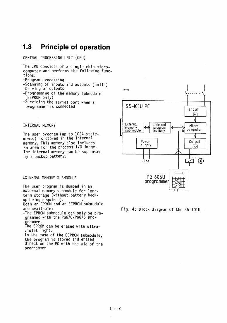
1.3 Principle of operation CENTRAL PROCESSING UNIT (CPU)
The CPU c o n s i s t s of a s i n g l e - c h i p mic ro- computer and performs t h e f o l l o w i n g func- t i o n s : -Program process ing -Scanning of i n p u t s and ou tpu ts ( c o i l s ) - D r i v i n g o f ou tputs -Programming o f t h e memory submodule
(EEPROM o n l y ) - S e r v i c i n g t h e s e r i a l p o r t when a
programmer i s connected
I NTERNAL MEMORY
The user program (up t o 1024 s t a t e - ments) i s s to red i n t h e i n t e r n a l memory. T h i s memory a l s o i nc ludes an area f o r t h e process 110 image. The i n t e r n a l memory can be supported b y a backup ba t te ry .
EXTERNAL MEMORY SUBMODULE
The user program i s dumped i n an e x t e r n a l memory submodul e f o r l ong- t e r m s torage (w i thou t b a t t e r y back-
- External Internal memor program < submoh~e memory
-. l
Power Output supply H
L
Line
up be ing requ i red ) . Both an EPROM and an EEPROM submodule are a v a i l a b l e : F i g . 4: B lock diagram o f t h e S5-101U -The EPROM submodule can o n l y be p ro - grammed w i t h t h e PG670lPG675 pro- g r ammer . The EPROM can be erased w i t h u l t r a - v i o l e t l i g h t .
- I n t h e case o f t h e EEPROM submodule, t h e program i s s to red and erased d i r e c t on t h e PC w i t h t h e a i d o f t h e programmer

PROGRAM PROCESSING
The c o n t r o l f u n c t i o n s o f t h e S5-101U a re de f i ned b y a user program. I-n order t o be a b l e t o scan t h e user program c y c l i c a l l y statement b y s ta te- ment, t h e CPU performs t h e f o l l o w i n g func t i ons :
1. I n t h e case o f a c o l d r e s t a r t (power sw i t ch from " O f f " t o "On" o r mode s e l e c t o r f rom "Stop" t o "RunM), t h e process o u t p u t image* i s erased, i.e. a l l ou tpu ts a re s e t t o zero.
2. The process i n p u t image* i s updated, i .e. a l l s i g n a l s ta tuses o f t h e i n - pu ts a r e scanned and w r i t t e n i n t o t h e process i nput image.
3. The user program (PB1 o r FBI ) i s scanned and processed statement b y statement. When scanning t h e s i g n a l s ta tuses o f t h e inputs, t h e CPU accesses t h e process i n p u t image and n o t t h e ac tua l inputs . When l a t c h i n g and un la tch ing t h e outputs ( c o i l s ) , o n l y t h e process ou tpu t image i s o v e r w r i t t e n t o beg in w i th .
4. Once t h e user program has been p ro - cessed, t h e process output image i s t rans fe r red t o t h e ac tua l o u t - puts.
5. P o i n t s 2, 3 and 4 a r e handled c y c l i c a l l y .
Cold restart 9 Erase process output image
H Read process input image
output image to the outputs
Fig . 5: P r i n c i p l e o f ope ra t i on o f t h e S5-101U
A scanning opera t i on f rom c y c l e checkpoint t o c y c l e checkpoint takes approx. 70 ms f o r 1024 statements ( b i n a r y ) . I f a scanning c y c l e i s n o t completed w i t h i n 300 ms due t o program e r r o r s *Process 1 /0 image: o r f a u l t s , an i n t e r n a l moni to r responds, I n t e r n a l memory area i n which t h e t h e PC en te rs t h e "Stop" s ta tus and s i g n a l s t a t u s ("Oii o r "1" ) of t h e a l l ou tpu ts ( c o i l s ) a re swi tched o f f . i npu ts /ou tpu ts i s stored.

2. Installation 2.1 Mechanical construction
Fig. 6: Dimension diagram o f t h e l O l U
The S5-101U c e n t r a l c o n t r o l l e r (CC) and t h e S5-101U expansion u n i t (EU) both have the same dimensinnc- Both u n i t s are attached s ide by s ide t o a v e r t i c a l mounting sur face by means of f o u r M4 b o l t s . The inputs and outputs must be a t t h e t o p and bottom ( i .e . t h e u n i t s must n o t be tu rned through 90 deg.).
When i n s t a l l i n g t h e u n i t s , make sure t h a t t h e maximum clearance o f 30 mm i s n o t exceeded.
I n order t o a v o i d t h e accumulation o f heat, make sure - t h a t t h e maximum angle o f i n c l i n a t i o n
of 22.5 deg. i s n o t exceeded - t h a t t h e minimum clearance o f 200 mm
between u n i t s mounted one above the o ther i s observed.
5mm dia. for M4 Leave up t o 4
55mm clear for program- mer connec - tor
Fig. 7: Wal l mounting arrangements
m c
\
7 - . . -- . -. -
I A
D
L" D

2.2 Electrical design Screw-type t e r m i n a l s are used on t h e The screws should be t i g h t e n e d w i t h SS-101U f o r a1 l e l e c t r i c a l connect ions. a t o r q u e o f between 80 and 120 Ncm. Each t e r m i n a l can take two conductors 10 mm o f i n s u l a t i o n should be removed w i t h t h e f o l l ow ing c ross -sec t i ona l f rom the end o f t h e leads. areas :
S o l i d conductors 1 .. .2.5mm 2
( 1 7 t o 13 AWG) Stranded conductors 0.75.. .1.5mm2
(18 t o 15 AWG) ( w i t h co re end s leeves)
2.2.1 Installation guidelines
The PC and f i e l d devices (sensors and a c t u a t o r s ) shou ld be connected up as shown below (Example: CC ( r e l a y ve rs ion ) and EU ( T r i a c v e r s i o n ) connected t o a common phase) :
Actuators \ Actuators 24V DC 220VAC 220 V AC 220 V AC
Potential equalizating connection
Fig . 8: I n s t a l l a t i o n schematic f o r t h e S5-101U PC and f i e l d devices

When connect ing up t h e PC, t h e f o l l o w - i n g p o i n t s shou ld be noted: -A common main swi tch ( 1 ) t o VDE 0113 o r i s o l a t i n g f a c i l i t y t o VDE 0100 must be p r o v i d e d f o r t h e PC, sensors and ac tuators .
-The power connect ions o f t h e CC and t h e EU must have a common f u s e (max. f u s e r a t i n g 6 A) ( 2 ) . The CC and EU need o n l y be fused s e p a r a t e l y i f t h e y a re connected t o d i f f e r e n t phases.
-Make su re t h a t t h e power connect ion and t h e i n p u t s and outputs o f t h e same u n i t a r e n o t connected t o d i f f e r e n t phases.
-A s m a l l e r conductor c ross -sec t i ona l a rea can be used w i thou t fuses ( 3 ) f o r t h e power connect ion o f t h e c o n t r o l c i r c u i t s i f t h e connect ing l i n e i s l e s s than 3 m long and i s p r o o f aga ins t e a r t h f a u l t s and s h o r t - c i r c u i t s .
-The power leads and 110 c a b l i n g must be r u n separa te ly .
-A power supp ly u n i t ( 4 ) must be p ro - v i d e d f o r t h e 24 V c o n t r o l c i r c u i t s . 24 V l i n e s must n o t be combined w i t h l i n e s c a r r y i n g h ighe r vo l tages i n a common cable. The sensors ( 5 ) can be powered b y t h e 24 V DC/300 mA power supp ly u n i t i n t h e PC (connect ion I ) o r b y an e x t e r - n a l 24 V power supp ly u n i t (connec- t i o n 11).
- I n c o n t r o l c i r c u i t s w i t h more than f i v e a c t u a t i n g c o i l s , g a l v a n i c i s o - l a t i o n by means o f a c o n t r o l t r a n s - former ( 6 ) i s recommended.
- A u x i l i a r y c i r c u i t s should be ea r thed e i t h e r a t one end ( a c t u a t o r s and sen- sors must be arranged a c c o r d i n g l y ) o r non-earthed a u x i l i a r y c i r c u i t s w i t h an i n s u l a t i o n mon i to r must be p ro - v ided. Earthed o p e r a t i o n by means o f a s t r a p ( 7 ) between t h e p r o t e c t i v e e a r t h con- duc to r and t h e power supp ly u n i t o r t r ans fo rmer i s t o be p r e f e r r e d .
-When connect ing up t h e s i g n a l leads o r bund l i ng such leads, make s u r e t h a t t h e v e n t i l a t i n g s l o t s o f t h e PC are n o t covered. Th i s a p p l i e s i n p a r t i c u l a r t o t h e v e n t i l a t i n g s l o t s above t h e screw te rm ina l s .
-Cables must n o t be r u n i n t h e imme- d i a t e v i c i n i t y o f t h e f r o n t p l a t e , o r between CC and EU.
-The programmable c o n t r o l l e r has a h i g h immunity t o no i se so t h a t con- t a c t o r s can n o r m a l l y be opera ted i n i t s immediate v i c i n i t y w i t h o u t hav ing t o t a k e any a d d i t i o n a l measures t o reduce no ise .
-Make sure t h a t t h e r e l a y c o n t a c t s o f t h e ou tpu ts a r e f i t t e d w i t h va- r i s t o r s (max. leakage c u r r e n t 1mA a t 275 vrms)
2.2.2 Connection of the expansion unit The l O l U c e n t r a l c o n t r o l l e r and S5-101U expansion u n i t a re connected t o each o t h e r b y a s h o r t f l a t r i b b o n cable.
S u f f i c i e n t con tac t t o chass is ground i s ensured b y secur ing t h e Cannon connector ( 1 ) w i t h two screws ( 2 ) . The t i g h t e n i n g t o r q u e o f t h e screws shou ld be 25...30 Ncm. On ly use M3x8 screws.
/I \ CC f i x i n g screw EU p o t e n t i a l
e q u a l i z a t i o n conductor The p o t e n t i a l e q u a l i z a t i o n conductor o f t h e EU must be donnected t o t h e CC. Con- F ig . 9: Connect ion o f t h e S5-101U expansic t a c t i s e s t a b l i s h e d b y a f i x i n g screw on u n i t t h e CC.

2.3 Terminal assignments of the central controller (CC)
2.3.1 Relay version (with full complement) (6ES5 101-8UA13)
Inputs 10.0 ... 1 2.3
---------- ---
Relay contacts connected in pairs
Line terminals to common potential
L-I N Outputs Q 0.0 ... Q 1.3 L-IN
Sensor fuse
Line fuse
Fig. 10: Terminal assignments of t h e S5-101U cen t ra l c o n t r o l l e r (CC) ( r e l a y vers ion) Conf igurat ion: 20 i n p u t s / l 2 outputs
L ine connection: 220 V o r 240 V AC
124~,,C + - 1
V 1 : Phase (220 V AC) V2: Phase (240 V AC) N : Neutra l @: Pro tec t i ve ea r t h
conductor
Sensor power supply: 24 V DC (max. 300 mA)
I 2 3 4 5 b 7 B 9 10 11 12 13 14 15 16 17 18 19 7024V"~I
The - 24 V DC termina l must be connected i n t e r n a l l y w i t h t h e inputs : I f an ex te rna l 24 V power supply u n i t i s used, i t s - 24 V DC termina l must be con- nected t o t he - 24 V DC termina l o f t h e CC. The + 24 V DC te rm ina l o f the CC remains f r e e i n t h i s case
2 - 4
1H4$30 l t o v . ~ 00 01 02 01 04-05 06 01 10 '12 11 i d 1s tbA1l 20 21 22 21, 0 0 0 0 0 0 0 0 0 ~ 0 0 0 0 0 0 0 0 0 0
SIEMENS Central unit
SlMATlC S5 101U Zentralgeriit 0 0 0 0
Slop Run 5V 8mtr1ob
E G
0 0 0 0 0 0 0 0 0 0 0 0 00 01 02 03 04 05 06 07 10 1 1 12 l3
m - 0 l 2 0, a c 6 G
r
PUlPG
B
T
hr., L" U1 M IN.. y l l W h & w @ \ l 2 1 12 23 ' 24 25 26' 27 11 19'10 31 32' 13 34 35' 36 37 38 :?A)
- L P
] 3 0 n m 2

2.3.2 Relay version (with partial complement )
(6ES5 101-8UB13)
Inputs 10.0 ... 1 2.2
Unassigned
Sensor fuse
Line fuse -
Unassigned -
Central unit SlMATlC S5 lOlU Zentralgerat
0 0 0
L+IL ' l L-I N
Outputs Q 0.0 ...Q 1.2 L+/L ' l L-IN
Fig. 11: Terminal assignments o f t he S5-101U cen t ra l c o n t r o l l e r ( r e1 ay vers ion) Conf igurat ion: 10 inputs /6 outputs

2.3.3 TRlAC version (6ES5 101-8UA23)
Line fuse
Inputs I 0.0 ... 1 1.7
0 0 0
Outputs Q 0.0 ...Q 0.3 Outputs Q 0.4 ...Q 0.7
L i n e connection: 220 V AC o r 240 V AC
Fig. 12: Terminal assignments o f t h e S5-101U c e n t r a l c o n t r o l l e r ( T r i a c ve rs ion )
V 1 : Phase (220 V AC) V2: Phase (240 V AC)
N: Neut ra l @: P r o t e c t i v e e a r t h conductor
E i g h t i n p u t s o r f o u r ou tpu ts connected t o common p o t e n t i a l .
Inputs /outputs and l i n e t e r m i n a l must be connected t o a common phase.

2.3.4 Transistor version (6ES5 101-8~A33) Inputs I E 0.0 ... E 2.3
L + - - - T T T I
Line fuse
~ o a d voltage -
Fig. 13: Terminal assignments o f t h e S5-101U c e n t r a l c o n t r o l l e r (T rans is to r vers ion) Complement: 20 i n p u t s / l 2 outputs
L ine connection:
L+: 24 V DC ( p o s i t i v e ) M: Reference vo l tage f rom L+ 0 V DC 4: System ground Sensor supp ly vo l tage:
24 V DC/rnin 0..3 A -Connections M y Mk, M$, and E are connected i n e rn l l y . Load vo l tage: 24 V DC
-M, M M M and E must a l s o be -The load vo l tage, sensor vo l tage and conn&fte?ly ex le rna l ly t o improve t h e l i n e vo l tage can be taken from a cu r ren t c a r r y i n g capac i ty . common source.

2.4 Terminal assignments of the expansion unit (EU)
2.4.1 Relay version ( 6 E S 5 1 0 1 - 8 U C l l )
Inputs 1 3.0 ... 15.3
Expansion unit SlMATlC S5 101U Erweitenrngsgertlt
Potential equalization: PE Potential Relay contacts connected in pairs
to common potential
L-IN L-l N
Fig. 14: Terminal assignments o f t h e S5-101U expansion u n i t ( r e l a y version)
L i n e connection: 220 V o r 240 V AC
Sensor power supply: 24 V DC (max. 300 mA)
V 1 : Phase (220 V AC) V2: Phase (240 V AC)
N: Neut ra l @: P r o t e c t i v e ear th conductor

2.4.2 TRlAC version ( 6 E S 5 101-8UC21)
Inputs 13.0 ... 13.7 Inputs 14.0 ... 14.7 L , , 1 L , , 1
Line fuse
Potential equalization: PE Potential
Line terminals .!?--Q Jf--j~ NU NU Qutputs Q 2.0 ...Q 2.3 Qutputs Q 2.4 ...Q 2.7
F ig . 15: Terminal assignments o f t h e S5-101U expansion u n i t ( T r i a c vers ion)
L i n e connection: 220 V o r 240 V AC
V 1 : Phase (220 V AC) V2: Phase (240 V AC)
N: Neutral @: P r o t e c t i v e e a r t h conductor
E i g h t i n p u t s o r f o u r o u t p u t s connected t o common potent i a l .
Inputs /outputs and l i n e t e r m i n a l must be connected t o a common phase.
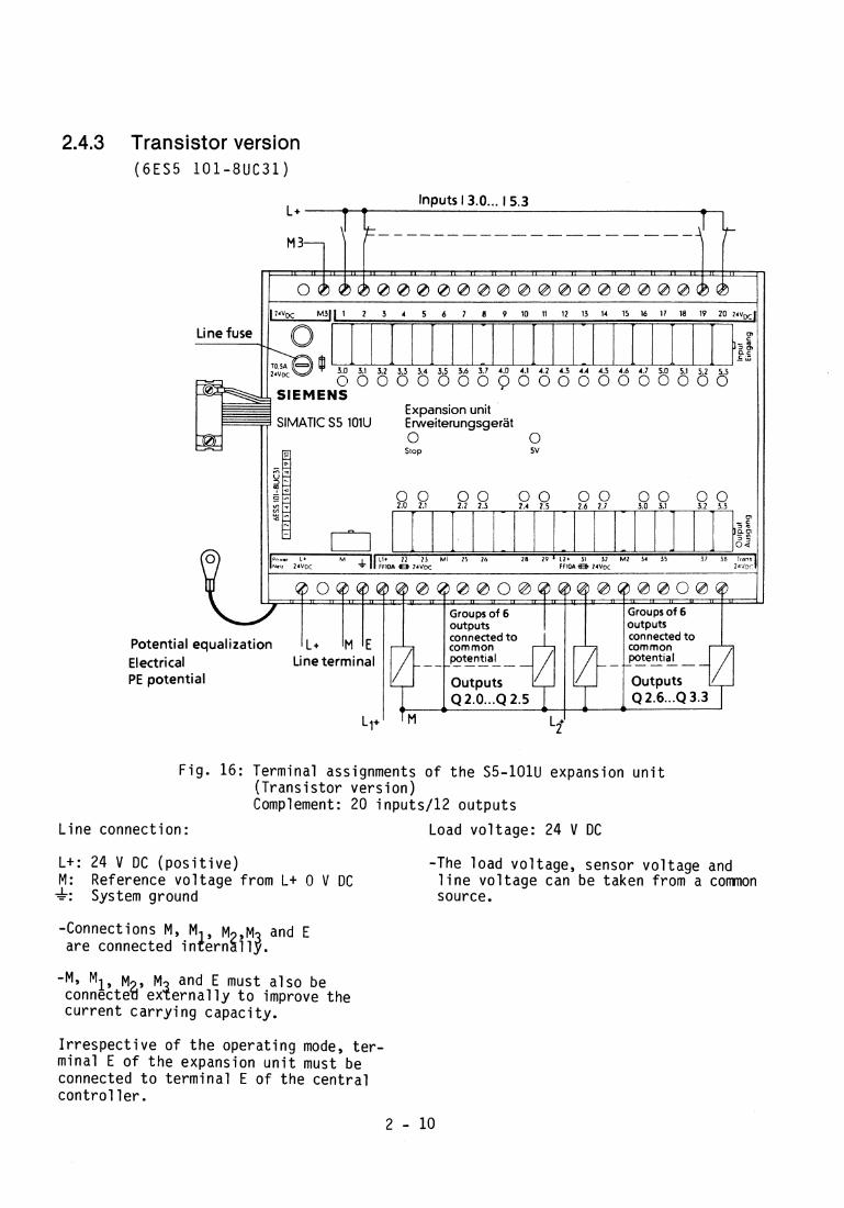
2.4.3 Transistor version ( 6 E S 5 101-8UC31)
Inputs 13.0 ... 15.3 L+ - - -
T T T 1
6 7 B 9 10 11 12 13 14 15 16 17 18 19 2 0 2 4 ~ ~
0
- 0
l;: C IL
5.5 5.6 F 7 4.0 4.1A4.2 4.3 4 4 - 4 . 5 4.6-4.7 5.0-5.1 5 .2 -5 .3
0 0 0 0 0 0 0 0 ~ 0 0 0 0 0 0 0 0 0 0 0
Expansion unit SlMATlC S5 lOlU Erweiterungsgerat
Slop 0 5 v
0 0 00 00 0 0 0 0 0 0 1.2 2.3 2.4 1.5 2.6 2.7 3.0 3.1 3.2 3.3 - - 'T . -
0 - C 3 11
'p A
v 2 Llr 22 25 M1 25 26 28 29 ' L ? + 31 31 M2 34 35 31 38 lran.
FFIOA B 2 4 V ~ 2 d ' J n ~
Electrical PE potential
Fig. 16: Terminal assignments of the S5-101U expansion unit (Transistor version) Complement: 20 inputs/l2 outputs
Line connection: Load voltage: 24 V DC
L+: 24 V DC (positive) -The load voltage, sensor voltage and M: Reference voltage from L+ 0 V DC line voltage can be taken from a comnon f: System ground source.
-Connections M, M M ,M and E are connected inl!&n$ll$.
-M, M1, M ~ , M? and E must also be connecte ex ernally to improve the current carrying capacity.
Irrespective of the operating mode, ter- minal E of the expansion unit must be connected to terminal E of the central controller.

3. Start up and operation 3.1 Controls and displays
F ig . 17: Con t ro l s and d i s p l a y s o f the l O l U PC
The green "5V" LED (1) i n d i c a t e s t h a t t h e i n t e r n a l power supply f o r t h e PC i s a v a i l a b l e . The r e d "Stop" LED ( 2 ) and t h e green "Run" LED ( 3 ) i n d i c a t e t h e two operat- i n g s t a t e s o f t h e PC. The "Stop" and "Run" ope ra t i ng s ta tes a re se lec ted w i t h t h e mode s e l e c t o r ( 4 )
The green LEDs f o r t h e i n p u t s ( 5 ) l i g h t up when t h e "1" s i g n a l i s a p p l i e d t o t h e i n p u t t e rm ina ls and thus i n d i c a t e t h e s i g n a l s t a t e of t h e i n p u t s d i r e c t . The green LEDs f o r t h e ou tpu ts ( 6 ) a r e con- nected i n p a r a l l e l w i t h t h e e x c i t a t i o n c o i l s o f t h e o u t p u t r e l a y s o r t h e d r i v e r s o f t h e outputs and i n d i c a t e t h e s i g n a l s t a t u s o f t h e outputs .
3.2 The "Run" and "Stop" modes
The l O l U PC has two opera t i ng modes - I1Stop1l and "Run". I n t h e "Stop" mode - r e d LED ( 2 ) i l l u - minated - t h e user program i s n o t pro-
cessed. A l l ou tputs o r c o i l s a re d i s - ab led i n t h i s mode. The PC a u t o m a t i c a l l y en te rs t h e "Stop" s t a t e when f a u l t s o r e r r o r s occur t h a t prevent proper pro- cess ing o f t h e program.
The "Stop" s t a t u s o f t h e PC can be e x i t e d again b y t u r n i n g t h e mode s e l e c t o r ( 4 ) t o t h e "Run" p o s i t i o n . The r e d LED ( 2 ) darkens and t h e green LED ( 3 ) l i g h t s up. The program i s pro- cessed i n t h i s mode. When t h e mode s e l e c t o r ( 4 ) i s i n t h e "Run" p o s i t i o n , t h e opera t i ng s t a t e o f t h e PC can be m o d i f i e d a d d i t i o n a l l y b y t h e "PC stop" and "PC s t a r t " f u n c t i o n s o f t h e p r o - grammer.
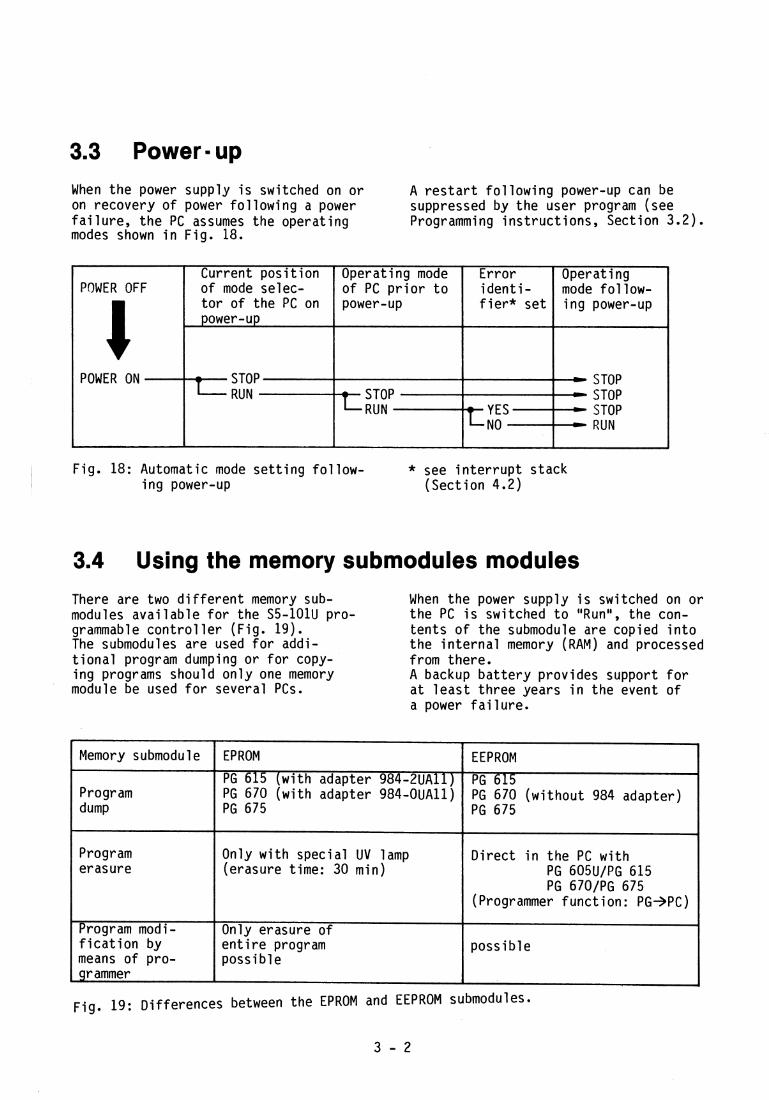
When t h e power supply i s switched on o r A r e s t a r t f o l l o w i n g power-up can be on recovery o f power f o l l o w i n g a power suppressed by the user program (see f a i l u r e , t h e PC assumes the operat ing Programming i n s t r u c t i o n s , Sect ion 3.2). modes shown i n F ig . 18.
Fig. 18: Automatic mode s e t t i n g f o l l o w - * see i n t e r r u p t s tack i n g power-up (Sec t ion 4.2)
POWER OFF
C POWER ON
3.4 Using the memory submodules modules There a re two d i f f e r e n t memory sub- When t h e power supp ly i s switched on o r modules a v a i l a b l e f o r the S5-101U pro- t h e PC i s swi tched t o "Run", t h e con- grammable c o n t r o l l e r (F ig . 19). t e n t s o f t h e submodule are copied i n t o The submodules are used f o r addi- t h e i n t e r n a l memory (RAM) and processed t i o n a l program dumping o r f o r copy- f rom there. i n g programs should o n l y one memory A backup b a t t e r y prov ides support f o r module be used f o r several PCs. a t l e a s t t h r e e years i n t h e event o f
a power f a i l u r e .
Current p o s i t i o n o f mode selec- t o r o f t he PC on power-up
- STOP L RUN
Fig. 19: D i f fe rences between the EPROM and EEPROM submodules.
3 - 2
Operat ing mode of PC p r i o r t o power-up
- STOP I- RUN
Memory submodule
Program dump
Program erasure
Program modi- f i c a t i o n by means o f pro- g r ammer
E r r o r i d e n t i - f i e r * s e t
---------- t YES
NO
EPROM
PG 615 ( w i t h adapter 984-2UAll) PG 670 ( w i t h adapter 984-OUAll) PG 675
Only w i t h spec ia l UV lamp (erasure time: 30 min)
Only erasure o f e n t i r e program poss ib le
Operat ing mode f o l l o w - i n g power-up
STOP STOP STOP RUN
EEPROM
PG 615 PG 670 ( w i t h o u t 984 adapter) PG 675
D i r e c t i n t h e PC w i t h PG 605U/PG 615 PG 670/PG 675
(Programmer f u n c t i o n : PG+PC)
p o s s i b l e

Fig. 20: PC power-up response w i t h and wi thout memory submodule
The dumping of t he program on memory submodules i s described i n t h e Pro- gramming Ins t ruc t ions , Sect ion "Pro- gram dump".
I f var ious programs have been dumped i n memory submodules, the r e l evan t pro- gram can be executed i n t h e PC s imp ly by rep lac ing the submodules.
PC fitted With back- up battery
-
-----------------c
Submodu l e program can be i n t e r - p re ted by PC
- YES
(EPROM plugged i n ) NO
NO (EEPROM plugged i n )
POWER OFF
4 POWER ON
The PC always copies t h e program from the memory submodule i n t o t h e i n t e r - na l program memory on power-up o r on recovery o f the power a f t e r a f a i l u r e as we1 l as when t h e mode se lec to r i S changed over t o "Run". A program already i n t he program memory i S overwr i t t e n even i f t he memory submodule plugged i n i s empty.
Program i n i n t e r n a l program memory
i S overwr i t ten b y t he program f rom the memory submodul e
- i s l o s t (PC "Stop")
i s l o s t ; EEPROM i s erased; reprogram- ming poss ib l e
- - i s l o s t
- i s r e ta i ned
External memory submo- dule plugged i n t o PC
+YES
D i f fe ren t programs can be loaded i n t o t he PC without t he a i d of a programmer by s imply in terchanging t he memory submodul es.
3.5 Operation with the expansion unit The f o l l ow ing po in ts should be g iven spec ia l a t t en t i on as the c e n t r a l c o n t r o l l e r (CC) and the expansion u n i t (EU)have separate power supply u n i t s :
- The outputs o f the CC and t he EU are disabled as soon as the PC en te rs t he "Stop" s ta te .
- I n the event o f a power f a i l u r e i n t he CC, t he EU automat ica l ly d isab les i t s outputs.
- I n the event o f a power f a i l u r e i n t h e EU, a l l inputs o f t he process 1/0 image which are assigned t o the EU assume s igna l s ta tus "1". (no t under undervol tage cond i t i ons )
The same appl ies i n t h e case o f a break i n t h e bus connect ion between t h e CC and t he EU. A f a u l t i n t h e EU can be detected by scanning i npu t I 5.3. This on ly appl ies t o t o t a l f a i l u r e .
I 5.3 = "1": F a u l t i n EU I 5.3 = "0": EU 0.k.
I f an expansion u n i t o f t h e r e1 ay version t r a n s i s t o r vers ion
i s used, i npu t I 5.3 must remain un- connected f o r t h i s purpose.

3.6 Operation in the SINEC L1 local area network
I I
F ig . 20 a: Example o f a SINEC L 1 network
S5 -1 15U The SINEC L 1 l o c a l area network i s used Master - PC f o r i n te rconnec t ing programmable c o n t r o l - l e r s o f t h e low-end performance range and operates on t h e Master-S1 ave p r i n c i p l e .
I I
The CP 530 communications processor i s I
always t h e master, and t h e s laves t h e CPUs I
PS
o f a1 l smal l PCs. A BT 777 bus te rm ina l f o r s i g n a l l e v e l
CPU
BT 7 7 7 bus terminal
CP 53 0
convers ion i s r e q u i r e d f o r each mode o r 55-10 1 U
s t a t i o n i n t h e network. Th is t e r m i n a l i s connected t o t h e programmer i n t e r f a c e p a r t of t h e s l a v e o r t o t h e SINEC L 1 p a r t of t h e CP 530. A four -core s h i e l d e d cable,
Slave -PC
SINEC L1-BUS
which i n te rconnec ts t h e var ious bus te rm ina ls , i s used as t h e a c t u a l t r a n s -
J vers ion medium. One master and up t o 30
55-115U Slave - PC
s laves can be connected t o t h e SINEC L 1 bus.
For f u r t h e r d e t a i l s , p lease r e f e r t o t h e I n s t r u c t i o n s and Programming I n s t r u c t i o n s o f t h e SINEC L 1 Local Area Network.
r i

3.7 Start -up
On PC s tar t -up, the f o l l o w i n g sequence o f operator procedures must be ob- served.
Condi t ion
Process and S5-101U PC dead, i .e. t he main swi tch (see Fig. 8 ) i s open.
Disconnect fuses f o r sensors and ac tuators . Switch o f f power c i r - c u i t s o f the actua- to rs . Close the main swi tch (see Fig. 8 )
I n s e r t t he fuses f o r the sensors. The fuse f o r the ac- t u a t o r s and power c i r c u i t s remain d i s - connected.
I n s e r t t h e fuses f o r the actuators. The power c i r c u i t s f o r the ac tuators remain disconnected (Fig. 8 ) .
The power c i r c u i t s f o r t h e ac tuators r e - main disconnected.
When the program has been f u l l y tested, swi tch on the power c i r c u i t s f o r t h e ac- tua to rs .
Operator procedure
-Check power te rm ina ls (PE conductor must be con- nected)
-Check whether a l l screw te rm ina ls are p r o p e r l y t i gh tened
-Make sure t h a t the re are no connect ions between 24V l i n e s and l i n e s c a r r y i n g h igher v01 tages.
-Withdraw t h e memory submodule
-Switch PC t o "Stop" w i th- o u t memory submodule and connect t h e PG 605U, 670 o r 675 programmer.
-Reset t h e PC w i t h t h e pro- grammer "ERASE PROGRAM" f u n c t i o n and then s e t the PC t o "Run"
-Actuate a l l sensors one a f t e r t h e other.
-Each ou tpu t o f t h e I/Os can now be d r i v e n w i t h the "Force" programmer func t ion .
-Put t h e PC t o "Stop" -Enter t h e program w i t h t h e
a i d o f t h e programmer and t r a n s f e r i t t o t h e PC
- Put t h e PC t o "Run", t e s t and c o r r e c t pro- gram.
- Put t h e PC t o "StopM.
-Put t h e PC t o "Run"
Remarks
V isua l check o f t h e system, observ ing VDE 0100 and 0113.
When t h e main s w i t c h i s c losed, t h e green "5V" and r e d "Stop" LEDs l i g h t up.
The r e d "Stop" LED dar- k e n ~ and t h e green "Run" l i g h t s up
I f t h e sensors a re pro- p e r l y connected, t h e co r - responding LEDs a t t h e i n p u t s w i l l l i g h t up.
The LEDs o f t h e f o r c e d ou tpu ts l i g h t up and t h e s w i t c h p o s i t i o n s o f t h e r e l e v a n t ac tua to rs change.
The r e d "Stop" LED l i g h t s up.
Set PC t o "Stop" b e f o r e debugging.
The PC must now pro- cess t h e program pro- pe r l Y

Maintenance and repair Error I Fault diagnosis
Most e r ro r s occur when en te r i ng and t e s t i n g t he program. I n these cases, de ta i l ed e r r o r i n - format ion i s provided by t h e pro- grammer. Th is i s described i n more deta i l i n t h e operat ing i n s t r u c t i o n s o f t he respec t i ve programmer. The programmer has t he f o l l o w i n g d iagnos t i c funct ions f o r t e s t i n g the program and f o r t roubleshoot ing: -"Program-independent s i gna l s ta tus
d isp lay" (Programming ins t ruc t ions , Sect ion 4 )
- "D i rec t s igna l s t a tus d isp lay " (Programming i ns t r uc t i ons , Sect i o n 4)
-Disp lay o f i n t e r r u p t stack ( P * 4.2)
I f the PC does n o t en te r t he "RunM s t a t e when t he power i s switched on o r t h e mode se lec to r i s actuated, o r should i t leave t h e "Run" s t a t e dur ing normal pro- cessing, t he cause of t h e i n t e r r u p t can be inves t iga ted w i t h t h e p rogramer "DISPLAY I-STACK" funct ion.
I n the event o f a f a u l t on t he 101U, t h e f o l l o w i n g t roubleshoot ing procedure i s r e - commended:
START 1
Put mode selector to "STOP" - Switch on power
4
I Put mode selector to "RUN" I I
NO Check mains voltage Green "+5V" LED l i t? Check mains fuse and terminals
L I AYES
m
YES All input LEDs always dark? m
c END 1
C NO
4 W
Fig. 21 : Troubleshooting procedure
Check fuses for sensor voltage Check sensor wiring
PC enters "RUN" mode?
YES YES
a
n
0 +
Interrupt stack (see p 4.21 .D
PC enters "STOP status during opemtion?
NO
YES Wrong or no progmm processing? W
1 NO
Check user program .c
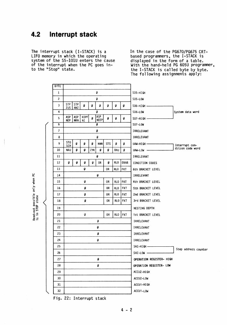
4.2 Interrupt stack
The i n t e r r u p t stack (I-STACK) i s a LIFO memory i n which t h e operat ing system o f t h e S5-101U enters t he cause of t he i n t e r r u p t when t h e PC goes i n - t o the "Stop" s ta te .
I n t h e case of t h e PG670/PG675 CRT- based programmers, t h e I-STACK i s displayed i n t h e form o f a tab le . With t h e hand-held PG 605U programmer, the I-STACK i S c a l l e d by te by byte. The f o l l o w i n g assignments apply:
SOS-HIGH
SD5-LOW
SD6-HI GH
SD6-LOW S y s t e m d a t a w o r d
SD7-HI GH
SD7-LOW
IRRELEVANT
IRRELEVANT
UAw-HIG" I I n t e r r u p t con -
UAW-LOW d i t i o n c o d e w o r d
IRRELEVANT
CONDITION CODES
6 t h BRACKET LEVEL
IRRELEVANT
4 t h BRACKET LEVEL
5 t h BRACKET LEVEL
2 n d BRACKET LEVEL
3 r d BRACKET LEVEL
NESTING DEPTH
1 s t BRACKET LEVEL
IRRELEVANT
IRRELEVANT
IRRELEVANT
IRRELEVANT
7 S t e p a d d r e s s c o u n t e r
SAZ-LOW
OPERATION REGISTER- H IGH
OPERATION REGISTER- LOW
ACCUZ-LOW
ACCU1-HIGH
Fig. 22: I n t e r r u p t stack

Explanations i n connection w i t h t he I-STACK
Byte 3 STPZUS : PC a t " S t ~ p ' ~ (externa l ; e.g. programmer) STPANZ : PC a t "Stop" ( i n t e r n a l )
Byte 5 KOPFNI : Block header cannot be i n t e rp re ted ASPNEP : User EPROM ASPNEEP: User EEPROM ASPNRA : User RAM
(no submodule inser ted)
Byte 9 STOSCH.: Mode se lec to r a t "Stop" NNN : Programming e r ro r ; i l lega l operat ion f o r lO lU STS : Programmable "Stop"
Byte 10 NAU : Power f a i l u r e ZYK: Scan t ime exceeded BAU : Ba t t e r y low
Byte 12 OR: I d e n t i f i e r b i t f o r OR memory VKE : Resul t o f l o g i c operat ion ERAB : I d e n t i f i e r b i t f o r f i r s t scan
Byte 13 FKT: Funct ion l = ~ ( ; 0=0(
I n t e r rup t cond i t i on code word: Provides i n d i c a t i o n o f reason f o r PC stopping and important po in te r s f o r t roub leshoot ing
Nesting depth: Binary/decimal d i sp l ay o f nest ing depth ( 1 ... 6)
STEP address counter: Ind ica tes t h e address a t which t h e program has aborted (1400H. . .1600H)
Accu 2/accu 1 : Ind ica tes t he p a t t e r n o f t he second- las t / l as t load operat ion.
4.3 Changing the backup battery
The l i t h i u m b a t t e r y has a support t ime o f a t l eas t th ree years.
Flag ( i n t e r n a l r e l a y ) F 63.6 i s s e t i f the voltage drops below the l e v e l r e - quired f o r b a t t e r y backup. The user program can thus respond accor- d i ng ly (see a1 so Programming I n s t r u c - t ions, Section 3.2).
The backup b a t t e r y can be changed w i t h the PC i n t he "Run" s ta te , proceeding as fo l l ows : - Remove t he cover o f t he b a t t e r y
compartment - Take ou t the o l d b a t t e r y - I n s e r t t h e new b a t t e r y ( no t i ng
p o l a r i t y ) - Replace t he b a t t e r y compartment
cover - Exhausted l i t h i u m b a t t e r i e s
are n o t rechargeable and must be disposed o f p r o p e r l y ( i .e no t s imply thrown i n t o a t r ash can).
Only t he l i t h i u m b a t t e r y i n the l i s t of spare pa r t s may be used.
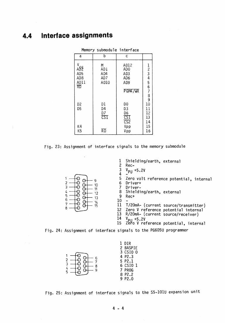
4.4 Interface assignments
Memory submodu l e i n t e r f a c e
Fig. 23: Assignment o f i n t e r f a c e s i g n a l s t o t h e memory submodule
a
:sr AD5 AD8 A D 1 1 m
D2 D 5
K4 K5
Sh ie ld ing lea r th , e x t e r n a l Rec- VPU +5.2V - Zero v o l t re fe rence p o t e n t i a l , i n t e r n a l D r i v e r t D r i v e r - Sh ie ld ing lea r th , e x t e r n a l Rec+ -
b
M AD l A D4 AD 7 AD10
D 1 D 4 D 7 CS 1
- R D
Tl20mA- ( c u r r e n t s o u r c e / t r a n s m i t t e r ) Zero V re fe rence p o t e n t i a1 i n t e r n a l Rl20mA- ( c u r r e n t sou rce / rece ive r ) Vpu +5.2V Zero V re fe rence p o t e n t i a l , i n t e r n a l
F ig . 24: Assignment o f i n t e r f a c e s i g n a l s t o t h e PG605U programmer
C
AD12 ADO A D3 AD6 A D9
PGM4/WR
D 0 D 3 D 6 m CS2 VP P v PP
1 D I R 2 BASPIE 3 CS10 0 4 P2.3 5 P2.1 6 CS10 1 7 PROG 8 P2.2
1 2 3 4 5 6 7 8 9
10 11 12 13 14 15 16
9 P2.0
Fig. 25: Assignment of i n t e r f a c e s i g n a l s t o t h e S5-101U expansion u n i t

5. Technical specifications 5.1 General data
Temperature range: Low temperature l i m i t 0°C ( K ) t o High temperature l i m i t 55OC ( v / ] m N Casing i n l e t a i r temp. 5 5 5 0 ~ 40 040 S t o r age temperature -4OoC.. .+70°C
Humidi t y r a t i n g : F t o DIN 40 040 95% r g l a t i v e atmospheric humid i t y a t 25 C
RF i n t e r f e r e n c e suppression: A t o VDE 0871 Impact t e s t : 15g/l lms, t rapezo ida l t o
Degree o f p r o t e c t i o n : DIN 40 046, P a r t 7 IP20 t o DIN 40 050 (no p r o t e c t i o n aga ins t water ) Weight: approx. 2.7 k g r e l a y / t r i a c
V i b r a t i o n t e s t t o DIN 40 046, P a r t 8 and IEC 68, P a r t 2-6
ve rs ion Creepage d is tances and c learances i n approx. 1.7 k g t r a n s i s t o r a i r t o VDE 0160 vers ion Dimensions: 285 mm X 167 mm X 114 mm (WxHxD)
(11. 2 i n . X 6.6 i n . X 4.5 in. )
Frequency range
10 t o 58 Hz
over 58 UP t o 500 Hz
* Power supply fuse: 250 mA slow (6.3~32 mm) A l l other fuses: 500 mA slow (6.3~32 mm)
Amp1 i tude o f a c c e l e r a t i o n
0,075 mm
- --
In terna l power supply f o r sensors
24 V W 3 0 0 mA (20 V...30 V)
Model
CC, r e lay 6ES5 1 0 1 - 8 ~ ~ 1 3 " 6ES5 101-8UB13
EU, re lay 6ES5 101-8UCll
CC T r i ac 6ES5 101-8UC23
EU Triac 6ES5 101-8UC21
( o n l y f o r 24 V ve rs ion ) The CC and EU a re p r o t e c t e d e l e c t r o n i c a l l y aga ins t p o l a r i t y r e v e r s a l . I f t h e v o l t a g e source has e l e c t r o n i c c u r r e n t l i m i t a t i o n , t h e dynamic ove r load f a c t o r o f t h e supp ly vo l tage must be 2 5 A and t h e l oad vo l tage
2 20 A t o t r i q q e r t h e appl iance fuses i n
d e f l e c t i o n
---
1 g
CC-transistor 6ES5 101-8UA33
EU-transistor 6ES5 101-8UC31
t h e case o f a f a t .
5 - 1
Power d iss ipat ibn a t f u l l load, typ ica l
29 W
22 W
23 W
23 W
18 W
Input v01 tage Tolerance, Frequency
220 V AC/240 V AC -15 %, + l0 % 48...63 Hz
220 V AC/240 V AC -15 %, + l 0 % 48...63 Hz
24 V DC rated 20 t o 30 V range inc lusive 3 V superimposed 0 ~ 8 '
Max. current consomption
260 mA
200 mA
200 mA
180 mA
150 mA
0.9 A
0.6 A
22 W
14 W
Fuse 6.3 X 32 mm 2 A; slow
Fuse 6.3 X 32 mm 0.5 A; slow

Power supply fuse: 1 A slow (6.3~32 mm) m) Sensor voltage fuse: 0,5 A slow (6.3~32 mm) )
CPU I memory submodule
In terna l power supply f o r sensors
24 V DC / 300 mA (20 V . . . 30V)
Operat ions : B i n a r y operat ions S e t t i ng / rese t t i ng operat ions Load and t r a n s f e r operat ions Tirner and counter opera t ions Comparison ( re1 a t i o n a l ) operat ions A r i thmet ic func t i ons D i g i t a l l o g i c S h i f t opera t ions Jump operat ions
Power d iss ipat ion a t f u l l load, typ ica l
29 W
I n t e r n a l program memory: RAM f o r 1024 statements; supported f o r a t l e a s t t h r e e years i f a back- up b a t t e r y i s used
Max . current consomption
520 mA
Model
CC-re1 ay 6ES5 101-8UU13 6ES5 101-8UW13
EU-re1 ay 6ES5 101-8UXll
Memory submodules (p lug - in ) : a) EPROM submodule f o r 1024 statements
Storage o f program: on PG 615 ( w i t h adapter 984-2UAll) on PG 670 ( w i t h adapter 984-OUAll) on PG 675
Input voltage Tolerance, Frequency
115 V AC -15% +10%
48 ... 63 Hz
Program erasure: UV lamp Processing t i m e f o r one b i n a r y ope ra t i on : approx. 70 p s b) EEPROM submodule f o r 1024 statements
Storage and e rasu re o f program a l s o d i r e c t on t h e PC w i t h a l l programmes
Addressing: CC E U 40 i n p u t s (10.0 ... 12.3) (13.0 ... 15.3) 24 outputs (QO.0.. .Q1.3) (~2 .0 . . .Q3.3)
512 f l a g s o r i n t e r - (FO.0.. .F63.7) na l r e l a y s
256 r e t e n t i v e (FO.0.. .F31.7)*
16 counters (CO.. .C15) Range 1. . .g99 16 t imers (TO.. .T15) Range 10 ms.. .9990s
* w i t h backup b a t t e r y o n l y
I n a l l models except t h e t r a n s i s t o r The s i g n a l s ta tuses o f t h e i n p u t s a re vers ion, t h e i npu ts are ga lvan i - i n d i c a t e d by green LEDs; t h e LEDs are c a l l y i s o l a t e d from t h e i n t e r n a l power d r i v e n by t h e s i g n a l v o l t a g e o f t h e supp ly by means o f optocouplers. inputs .
CC (relay version) 6ES5 101-8UA13, 6ES5 101-8UU13 EU (re1 ay version) 6ES5 101-8UCl1, 6ES5 101-8UXll
Number o f i n p u t s
2 0 f l o a t i n g
I n s u l a t i o n Nomtnal i n p u t c u r r e n t f o r
signal
8.5 mA 1)
y)::y:l$
36 V DC
Rated i n p u t voltage
24 V DC
tested at
500 V AC
Maximum l e n g t h o f l i n e (24 V DC and 220 V 1 i nes r u n separa te l
600 m
Rated i n p u t vo l tage f o r Delay, t y p i c a l
"0" s igna l
-35V.. .+4.5V
o r i n p u t open
ON
3 ms
"l" s i g n a l
+13V.. .+35V
OFF
6 ms

1 ) Appl ies a l s o t o two-wire p r o x i m i t y switches (vol tage: 22V...30V DC) 2) I f an e x t e r n a l power supply u n i t i s used, a smoothing capac i to r must
be f i t t e d 3) Card r e l a y s o f t ype E V23027-8002-A402 (SIEMENS); leakage c u r r e n t o f
p a r a l l e l var is tor+ lmA. 4) To VDE 0660, P a r t 200
Number of outputs
12 r e l a y s Connected i n p a i r s t o common p o t e n t i a l
3 1
CC (relay version) 6ES5 101-8UB13, 6ES5 101-8UW13
Contact sw i tch ing capac i t y
I :5A I ~ ~ $ ~ ~ I ) : I . ~ ~ ~ 5 0 I~(DCII) :0.5 A / 30 V p t l o t duty ra t ing : 6300, R300
1) Appl ies a l s o t o two-wire p r o x i m i t y switches (voltage: 22V...30 V DC) 2) If an e x t e r n a l power supply u n i t i s used, a smoothing capac i ta r must
be f i t t e d 3) Card r e l a y s o f t ype E V23027-8002-A402 (SIEMENS); leakage c u r r e n t of
p a r a l l e l v a r i s t o r ImA. 4) To VDE 0660, P a r t 200
The s i g n a l statuses o f the outputs are The r e l a y contac ts are f i t t e d w i t h i n d i c a t e d by green LEDs connected i n v a r i s t o r s (maximum leakage c u r r e n t p a r a l l e l w i t h the e x c i t a t i o n c o i 1s o f 1 mA) the re lays .
Serv ice l i f e i n sw i tch ing cyc les
1.5 X 10⁶ 2.0 X 10⁵
Number o f i npu ts
I 0 f l o a t i n g
CC ( T r i a c ve rs ion ) 6ES5 101-8UA23 EU ( T r i a c vers ion) 6ES5 101-8UC21
I n s u l a t i o n
sw i tch ing frequency
10 H z r e s i s t 2 HZ induc t .
Rated i n p u t voltage
24 V DC 2,
for
v01 tage
36 V DC
t e s t e d a t
500 V AC
Number of outputs
Number o f i npu ts
16 f l o a t . groups of 8 connec.
. .
1) S u i t a b l e f o r AC-proximi t y switches
D i v e r s i t y f a c t o r
100%
Number o f outputs
groups Of
netted t o on p0 t e n t i a l and w i t h 10 A FF ( f a s t ) fuse
The s igna l statuses o f the outputs are ind ica ted by green LEDs connected i n p a r a l l e l w i t h the Tr iacs .
5 - 3
Rated i n p u t vo l tage f o r
Contact sw i tch ing frequency frequency switching
10 H z r e s i s t . 2 Hz induc t .
Rated i n p u t voltage
220 V AC +20%
f
for I n s u l a t i o n
Nominal i n p u t u r r e n t f o r
signal "0" s igna l
Serv ice l i f e i n sw i tch ing c y c l e
D i v e r s i t y f a c t o r (numb. o f outputs ~ o n ~ s i m u l t a n e i t y ) , " ~ ~ : ~ ~ ~
100%
I n s u l a t i o n
TOO9
Output current for "1" s igna l and a t 264 V AC
50mA.. . l .OA r e s i s t . 50mA.. .0.5A induct . Lamp load max. 60 W
nominal v o l t a g e
"1" s igna l
1.5 X 10⁶ 2.0 X 10⁵ 'yCV 6 r e l a y s
grouped in pairs
3
tes ted a t
2.0 kV AC
-35V.. .+4.5V
o r i n p u t open
tes ted at
2 - O k V A C 1 . 5 ~ 4 ) It?%ll) :1.5 AI250 V 1 ~ ( ~ ~ 1 1 ) : 0 . 5 A/ 30 V ~ e l o t duty r a t i n g : 8300, R300
Rated i n p u t vo l tage f o r
Leakage c u r r e n t for "0" signal
max. 5 mA
Maximum l e n g t h of l i n e (24 V DC and 220 V lines run separately)nominal
Delay, t y p i c a l
Nominal i n p u t u r r e n t
:l,, signal
typ. 2 0 m A 1 )
"0" s i g n a l
0. ..40 V AC
or input open
600 m
ON
3 ms +13V.. .+35V
"1" s igna l
159 ... 264 Y AC
Maximum s w i t c h i n g frequency
10 2 Hz Hz r e s i s t i n d u c t Lamp load
8 Hz
OFF
6 ms 8.5 mA 1 )
Delay and switching
forfrequency,,typical
D i v e r s i t y f a c t o r f a c t o r
100%
Maximum l e n g t h o f l i n e (24 V DC and 220 V 1 ines r u n separately)~,$~!'~~
300 m
ON
8 m s .
OFF
1 5 m s
for I n s u l a t i o n
I n s u l a t i o n
10 Hz
nominal vo l tage
*yCv
for
250V AC
tes ted a t
1 . 5 k V A C
tested at
2.0 kV AL

CC ( t r a n s i s t o r vers ion) 6ES5 101-8UA33 EU ( t r a n s i s t o r vers ion) 6ES5 101-8UC31
The inpu ts are ga lvan ica l l y connected Green LEDs d i s p l a y t h e s ta tuses o f t h e v i a reference p o t e n t i a l M w i t h t h e i n - inputs . The LEDs a r e powered by the p u t and t h e load vo l tage ?outputs) . s igna l vo l tage o f t h e i npu ts .
1) Applies also to two-wire proximity switch) (voltage: 22 V...30 V DC)
2) If an external power supply unit is used, a smoothing capacitor must be fitted
Number of inputs
20 non- floating
The outputs are connected g a l v a n i c a l l y v i a The LEDs a r e powered b y t h e l o a d vo l tage reference p o t e n t i a l M1 and M~ w i t h of t h e outputs . Load v o l t a g e range t h e l i n e i n p u t and t h e sensor voltage. = 20 V t o 30 V DC 0 Hz i n c l u s i v e o f The statuses o f t h e i n p u t s a r e d i sp layed superimposed AC v01 tage. b y green LEDs swi tched i n p a r a l l e l t o t h e P P outputs.
Rated input voltage
24 V DC 2)
L i m i t a t i o n o f v01 tage induced on c i r c u i t i n t e r r u p t i o n a t V 5 3 0 V D C : r - 2 . 5 V ~ h o r h - c i r c u i t p r o t e c t i o n : e l e c t r o n i c
- a l l ou tpu ts c u r r e n t - l i m i t e d - cons tan t s h o r t - c i r c u i t pe rm iss ib le o n l y f o r one o u t p u t
a t Tu S +30 'C Max. l e a d r e s i s t a n c e 1.5 Ohm
Number of outputs
12 non-floating, connected in groups Of to common potential and 10 A superf ast fuse
<
Input voltage for
Output current at "l" signal and VL
Signal l e v e l : v 1 5 V
~ ~ ~ ~ i ~ o t t o M$X: 0.5 A to T 5 + 5 5 0 ~ L'& l ead
5s0c iYt$IT~ 5 40°C
UtatedEN = l0 Induct ive load: B U t o ru 5 +5s0c
Nominal input current for "1" signal
8.5 mA 1)
"0' signal
-35V..+4.5V
or input open
"l" signal
+13V...+35V
Residual c rrent at "8" signal
Max. 1mA
Insulation for nominal voltage
None - non-floating
Max. switching frequency
100 Hz resistive without allowing for cycle time 2 Hz inductive 8 Hz lamp load
t
Maximum length of line (24 V DC and 220 V lines run separately)
600 m
Delay, typical ON
3 ms
Diversity factor (number) outputs "on simultaneity
100 %
OFF
6 ms
Max. lead length
100 m

Spare parts and accessories
* E = Inputs A = Outputs
Obtainable from EWA Exceptions:: ** Obtainable from GWK *** Obtainable from Werkstatt Furth
984 U adapter ** PG670 programner adapter for the memory submodules of the U-type PCs
UV erasing facility ** S5-101 simulator (for the 55-101 with 24 V inputs) ***
Lithium battery (for RAM backup)
G-type fuse-link 6.3 X 32 mn 250 mA (slow) (10 pcs.) 500 mA (slow) (10 pcs.) 10 AF (fast) (10 pcs.)
1 A (slow) (10 PCS.) 2 A (slow) (10 pcs.)
731 interconnecting cable (1=3, 2 m) * for connecting up the PG670/PG675 progrmers to the lOlU PC
PG605U programner with
German labelling
English labelling
French labelling
Carrying case for the PG 605U programner PG 615 progrmer, German labelling (without Operating system submodule) Operating system submodule for PG 615 programner German English French
lOlU PC manual German English French
6ES5 375-OLCll
6ES5 984-OUAll
6ES5 985-OAAll
6ES5 788-OLBll
6ES5 980-OAEll
6ES5 980-3BAll 6ES5 980-3BA21 6ES5 980-3BC41 6ES5 980-3BA31 6ES5 980-3BA71
6ES5 731-1BD20
6ES5 605-OUAll
6ES5 605-OUBll
6ES5 605-OUCll
6ES5 986-OLAll
6ES5 615-OUAll
6ES5 815-OUAll 6ES5 815-OUBll 6ES5 815-OUCll
6ES5 998-OUC13 6ES5 998-OUC23 6ES5 998-OUC33