service manual - service-engine.com.ua avensis 2ad-ftv f… · diesel injection pump common rail...
TRANSCRIPT
Diesel Injection Pump
Common Rail System for TOYOTA AVEN-SIS 2AD-FTV/FHV Engine
OPERATION
May, 2005
00400522E
SERVICE MANUAL

1–2

© 2005 DENSO CORPORATIONAll Rights Reserved. This book may not be reproducedor copied, in whole or in part, without the writtenpermission of the publisher.

Table of Contents
Table of Contens
Operation Section
1. PRODUCT APPLICATION INFORMATION1.1 Outline . . . . . . . . . . . . . . . . . . . . . . . . . . . . . . . . . . . . . . . . . . . . . . . . . . . . . . . . . . . . . . . . . . . . . . . . . . . . . . . . 1-1
1.2 Application . . . . . . . . . . . . . . . . . . . . . . . . . . . . . . . . . . . . . . . . . . . . . . . . . . . . . . . . . . . . . . . . . . . . . . . . . . . . . 1-1
1.3 System Components Parts Number . . . . . . . . . . . . . . . . . . . . . . . . . . . . . . . . . . . . . . . . . . . . . . . . . . . . . . . . . 1-1
2. OUTLINE OF SYSTEM2.1 Outline of Composition and Operation . . . . . . . . . . . . . . . . . . . . . . . . . . . . . . . . . . . . . . . . . . . . . . . . . . . . . . . 1-3
3. SUPPLY PUMP3.1 Outline . . . . . . . . . . . . . . . . . . . . . . . . . . . . . . . . . . . . . . . . . . . . . . . . . . . . . . . . . . . . . . . . . . . . . . . . . . . . . . . . 1-4
3.2 SCV . . . . . . . . . . . . . . . . . . . . . . . . . . . . . . . . . . . . . . . . . . . . . . . . . . . . . . . . . . . . . . . . . . . . . . . . . . . . . . . . . . 1-4
4. RAIL4.1 Outline . . . . . . . . . . . . . . . . . . . . . . . . . . . . . . . . . . . . . . . . . . . . . . . . . . . . . . . . . . . . . . . . . . . . . . . . . . . . . . . . 1-5
4.2 Pressure limiter . . . . . . . . . . . . . . . . . . . . . . . . . . . . . . . . . . . . . . . . . . . . . . . . . . . . . . . . . . . . . . . . . . . . . . . . . 1-5
5. INJECTOR5.1 Outline . . . . . . . . . . . . . . . . . . . . . . . . . . . . . . . . . . . . . . . . . . . . . . . . . . . . . . . . . . . . . . . . . . . . . . . . . . . . . . . . 1-6
5.2 Operation (Piezo Injector for 2AD-FHV) . . . . . . . . . . . . . . . . . . . . . . . . . . . . . . . . . . . . . . . . . . . . . . . . . . . . . . 1-7
6. DESCRIPTION OF CONTOROL SYSTEM COMPONENTS6.1 ECU Connector Terminal Layout . . . . . . . . . . . . . . . . . . . . . . . . . . . . . . . . . . . . . . . . . . . . . . . . . . . . . . . . . . . . 1-9
6.2 EDU (Electronic Driving Unit) . . . . . . . . . . . . . . . . . . . . . . . . . . . . . . . . . . . . . . . . . . . . . . . . . . . . . . . . . . . . . 1-11
7. FUEL INJECTION TIMING CONTROL7.1 Outline . . . . . . . . . . . . . . . . . . . . . . . . . . . . . . . . . . . . . . . . . . . . . . . . . . . . . . . . . . . . . . . . . . . . . . . . . . . . . . . 1-14
7.2 Injection Pattern. . . . . . . . . . . . . . . . . . . . . . . . . . . . . . . . . . . . . . . . . . . . . . . . . . . . . . . . . . . . . . . . . . . . . . . . 1-14
7.3 Control Timing . . . . . . . . . . . . . . . . . . . . . . . . . . . . . . . . . . . . . . . . . . . . . . . . . . . . . . . . . . . . . . . . . . . . . . . . . 1-15
8. DIAGNOSTIC TROUBLE CODES (DTC)8.1 About the Codes Shown in the Table . . . . . . . . . . . . . . . . . . . . . . . . . . . . . . . . . . . . . . . . . . . . . . . . . . . . . . . 1-16
8.2 Diagnosis Trouble Code Table . . . . . . . . . . . . . . . . . . . . . . . . . . . . . . . . . . . . . . . . . . . . . . . . . . . . . . . . . . . . 1-16
9. EXTERNAL WIRING DIAGRAM9.1 ECU External wiring diagram . . . . . . . . . . . . . . . . . . . . . . . . . . . . . . . . . . . . . . . . . . . . . . . . . . . . . . . . . . . . . 1-23

1–2

Operation Section1–1
1. PRODUCT APPLICATION INFORMATION
1.1 OutlineThe common rail system installed on the TOYOTA Avensis now employs the 2AD-FHV or 2AD-FTV model engines.
For information on the basic CRS system, refer to "New Common Rail System with DPNR for TOYOTA Avensis" issued in October
2003 (Service Bulletin ECD 0302E.) Changes to old models are explained in each section.
The piezo injector newly employed in the 2AD-FHV
1.2 ApplicationThe new 2AD-FHV and 2AD-FTV are employed in place of the discontinued 1CD-FTV.
The Avensis exhaust volume has changed from 2.0L to 2.2L.
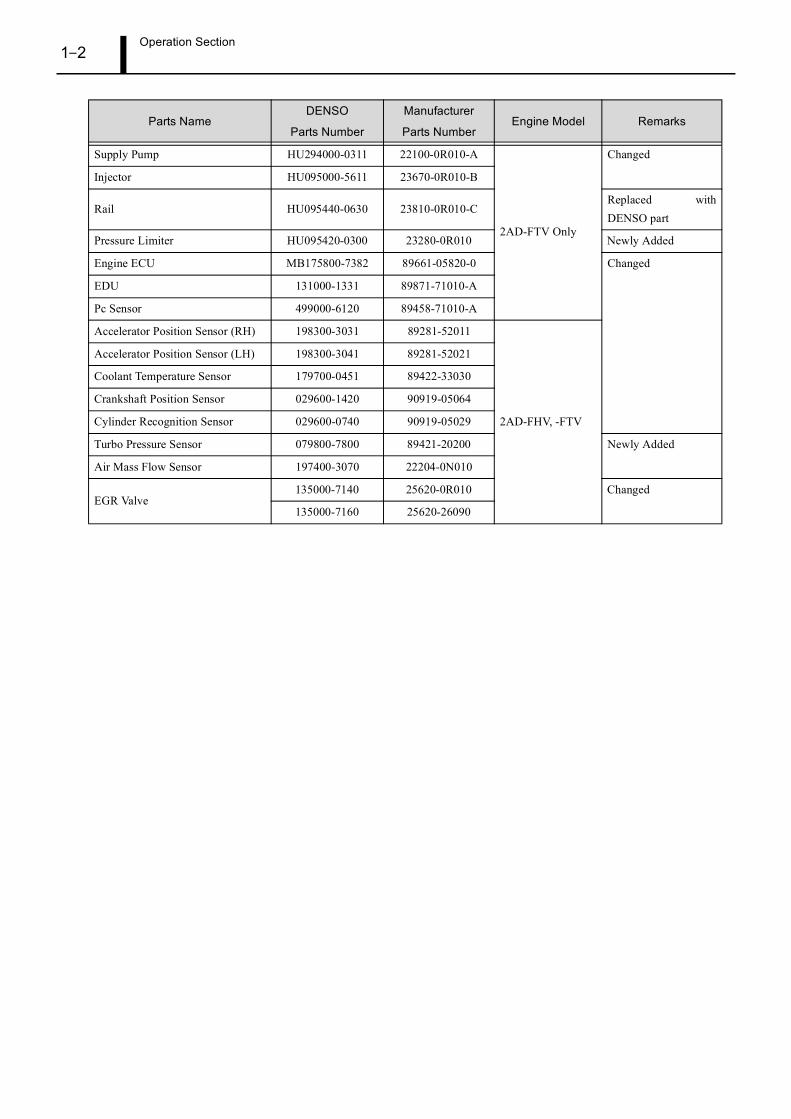
1.3 System Components Parts NumberBelow is a list of CRS related parts. Whether a particular part has changed or not is recorded in the "Remarks" column.
Vehicle Name Vehicle Model Engine Model Exhaust Volume Start of Production
Avensis ADT2512AD-FHV
2.2L April, 20052AD-FTV
Parts NameDENSO
Parts Number
Manufacturer
Parts NumberEngine Model Remarks
Supply Pump HU294000-0301 22100-0R020-A
2AD-FHV Only (For DPNR system)
Changed
Injector (Piezo Injector) 295900-0011 23670-26011-A New Design
Rail HU095440-0620 23810-0R020-CReplaced withDENSO part
Discharge Valve 294290-0051 23990-30020 Changed
Engine ECU MB175800-7372 89661-05A20-0
EDU 131000-1370 89871-20070
Pc Sensor 499000-6080 89458-60010
Exhaust Fuel Addition Injector 297700-0030 23710-26010
DPNR Element 253600-0020 A9945-22013
A/F Sensor211200-0400 89467-20060
211200-0410 89467-20070
Exhaust Gas Temperature Sensor265600-0871 89425-20360
265600-0882 89425-20370
Differential Pressure Sensor 104990-1000 89480-20020 No Change
Operation Section1–2
Supply Pump HU294000-0311 22100-0R010-A
2AD-FTV Only
Changed
Injector HU095000-5611 23670-0R010-B
Rail HU095440-0630 23810-0R010-CReplaced withDENSO part
Pressure Limiter HU095420-0300 23280-0R010 Newly Added
Engine ECU MB175800-7382 89661-05820-0 Changed
EDU 131000-1331 89871-71010-A
Pc Sensor 499000-6120 89458-71010-A
Accelerator Position Sensor (RH) 198300-3031 89281-52011
2AD-FHV, -FTV
Accelerator Position Sensor (LH) 198300-3041 89281-52021
Coolant Temperature Sensor 179700-0451 89422-33030
Crankshaft Position Sensor 029600-1420 90919-05064
Cylinder Recognition Sensor 029600-0740 90919-05029
Turbo Pressure Sensor 079800-7800 89421-20200 Newly Added
Air Mass Flow Sensor 197400-3070 22204-0N010
EGR Valve135000-7140 25620-0R010 Changed
135000-7160 25620-26090
Parts NameDENSO
Parts Number
Manufacturer
Parts NumberEngine Model Remarks

Operation Section1–3
2. OUTLINE OF SYSTEM
2.1 Outline of Composition and Operation
(1) 2AD-FHV
• The 2AD-FHV newly employs a piezo injector and compact SCV.
(2) 2AD-FTV
• The 2AD-FTV newly employs a pressure limiter and compact SCV.
Operation Section1–4
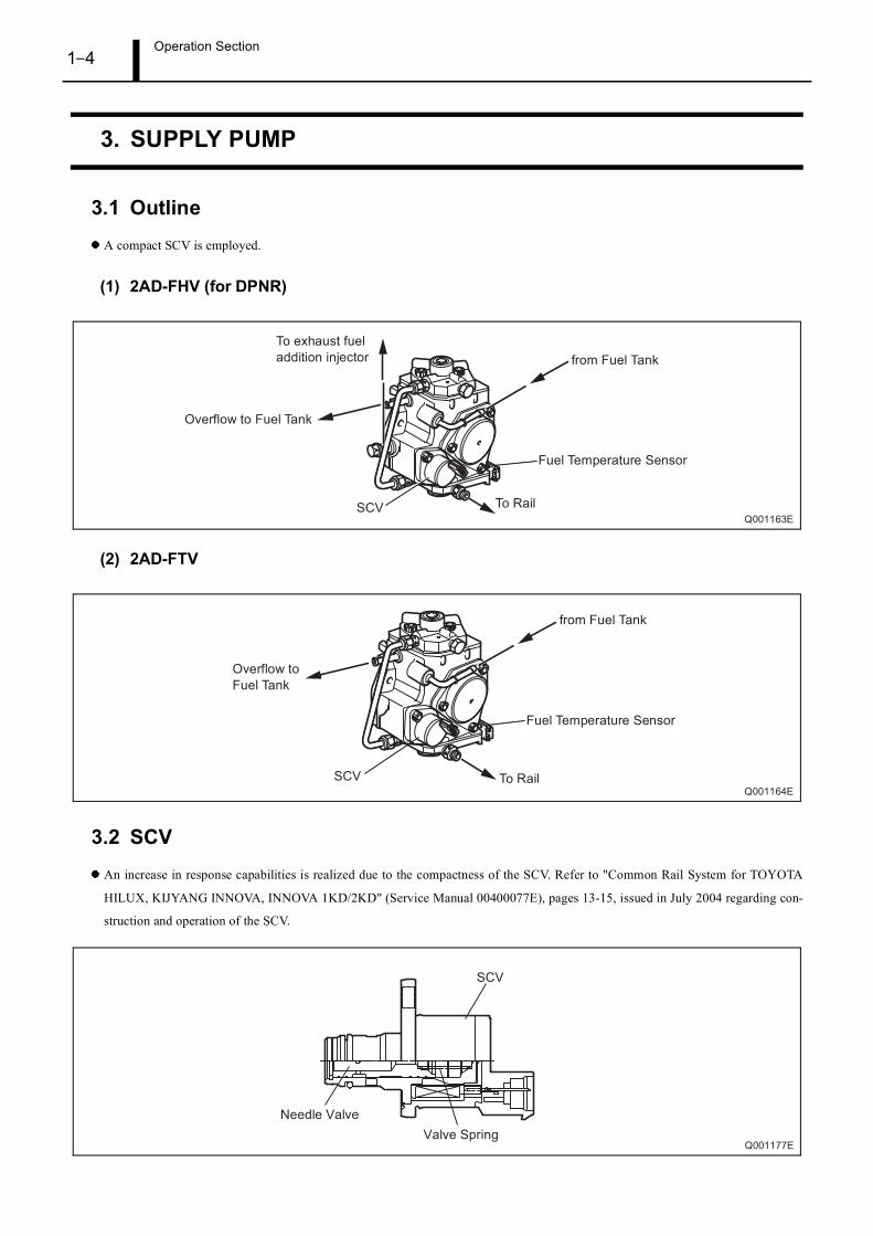
3. SUPPLY PUMP
3.1 OutlineA compact SCV is employed.
(1) 2AD-FHV (for DPNR)
(2) 2AD-FTV
3.2 SCVAn increase in response capabilities is realized due to the compactness of the SCV. Refer to "Common Rail System for TOYOTA
HILUX, KIJYANG INNOVA, INNOVA 1KD/2KD" (Service Manual 00400077E), pages 13-15, issued in July 2004 regarding con-
struction and operation of the SCV.

Operation Section1–5
4. RAIL
4.1 Outline
(1) 2AD-FHV
• The 2AD-FHV rail has been changed from a non-DENSO product to a DENSO-made rail.
(2) 2AD-FTV
• The 2AD-FTV rail has been changed from a non-DENSO product to a DENSO-made rail.
• A pressure limiter is newly employed in place of the discontinued pressure discharge valve.
4.2 Pressure limiterThe pressure limiter releases pressure when the internal pressure of the rail becomes abnormally high. The pressure limiter opens when
internal pressure reaches 211MPa (kg/cm2) and closes when rail pressure reaches a given set pressure. Fuel released from the pressure
limiter is returned to the fuel tank.

Operation Section1–6
5. INJECTOR
5.1 Outline
(1) 2AD-FHV
• The piezo injector is comprised of a piezo stack, large and small pistons, three-way valve and a needle.

Operation Section1–7
(2) 2AD-FTV
• The G2 injector employed on the 2AD-FTV has changed from the old conventional shape.
• The G2 injector has not changed in regards to the old model.
5.2 Operation (Piezo Injector for 2AD-FHV)The piezo injector newly employed in the 2AD-FHV increases responsiveness and makes more precise control possible.
The piezo element expands when voltage is applied. The piezo injector uses this characteristic to control the pressure of the control
chamber, open and close the needle, and control the start and stop of injection through moving the three-way valve up and down.

Operation Section1–8
The following explains piezo injector operation (reference items (1) - (3) below.)
(1) Non-injection
•When the piezo element is not energized, the inside of the control chamber and the needle have the same fuel pressure applied to them
from the rail, causing the needle to close under needle spring pressure.
(2) Injection
•When the piezo element is energized it expands, pushing the large and small pistons downward.
This further pushes the three-way valve downward, opening the upper sheet and closing the lower sheet. As a result, the passage to
the control chamber is sealed off. Since there is not a rapid transfer of pressure to the control chamber due to orifice "A", the pressure
in the control chamber drops off.
Due to the drop in fuel pressure in the control chamber, the fuel pressure placed on the needle is greater, pushing the needle upwards
and allowing injection to begin.
(3) End of injection
• Once the piezo element is de-energized it begins to contract, allowing the large piston, small piston and three-way valve to travel up-
wards. The three-way valve closes the upper sheet and opens the lower sheet.As a result, the passage to the control chamber opens,
instantaneously making the fuel pressure inside the control chamber return to rail pressure. The needle is pushed down, and injections
stops.
Operation Section1–9
6. DESCRIPTION OF CONTOROL SYSTEM COMPONENTS
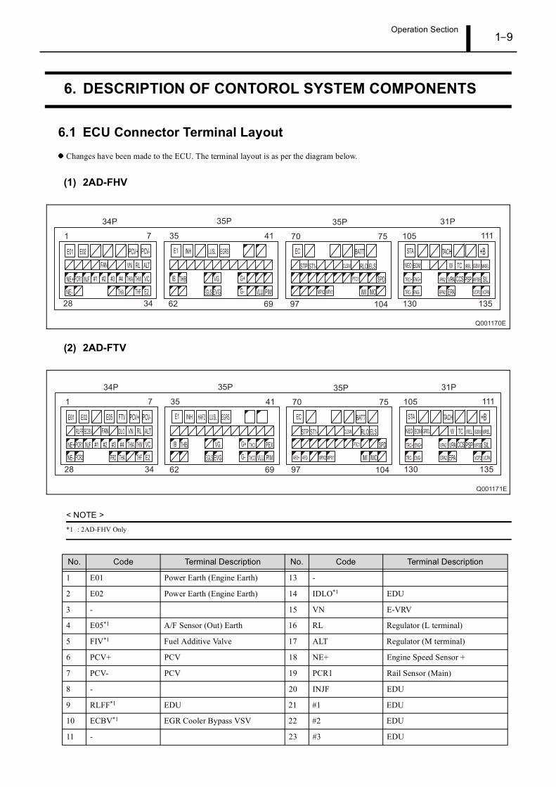
6.1 ECU Connector Terminal LayoutChanges have been made to the ECU. The terminal layout is as per the diagram below.
(1) 2AD-FHV
(2) 2AD-FTV
< NOTE >
*1 : 2AD-FHV Only
No. Code Terminal Description No. Code Terminal Description
1 E01 Power Earth (Engine Earth) 13 -
2 E02 Power Earth (Engine Earth) 14 IDLO*1 EDU
3 - 15 VN E-VRV
4 E05*1 A/F Sensor (Out) Earth 16 RL Regulator (L terminal)
5 FIV*1 Fuel Additive Valve 17 ALT Regulator (M terminal)
6 PCV+ PCV 18 NE+ Engine Speed Sensor +
7 PCV- PCV 19 PCR1 Rail Sensor (Main)
8 - 20 INJF EDU
9 RLFF*1 EDU 21 #1 EDU
10 ECBV*1 EGR Cooler Bypass VSV 22 #2 EDU
11 - 23 #3 EDU

Operation Section1–10
12 Cooling Fan Relay 24 #4 EDU
25 THIA Intake Air Temp. Sensor 63 -
26 THW Coolant Temp. Sensor 64 EGLS EGR Lift Sensor
27 VC Sensor Power Supply 65 EVG Air Flow Meter Earth
28 NE- Engine Speed Sensor - 66 G- Cylinder Recognition Sensor -
29 PCR2*1 Rail Sensor (Sub) 67 THCO*1 Exhaust Gas Temp. Sensor (Out)
30 PRD*1 EDU 68 VLU Diesel Throttle Position Sensor
31 THA Air Temp. Sensor 69 PIM Turbo Pressure Sensor
32 - 70 EC Body Earth
33 THF Fuel temp. Sensor 71 -
34 E2 Sensor Earth 72 -
35 E1 Earth (Engine Earth) 73 -
36 INH Combination Switch 74 BATT Battery
37 HAF2*1 A/F Sensor (Out) Heater 75 -
38 LUSL Diesel Throttle Drive IC 76 -
39 EGRS EGR Linear Solenoid 77 STP Stop Light Switch
40 VCS*1 Rail Pressure Sensor (Power Supply)
78 ST1- Stop Light Switch
41 E2S*1 Rail Pressure Sensor (Earth) 79 -
42 - 80 -
43 - 81 -
44 - 82 CLSW Clutch Switch
45 - 83 -
46 - 84 RLO Regulator
47 - 85 ELS Tail Light Relay
48 - 86 -
49 - 87 -
50 - 88 -
51 - 89 -
52 - 90 -
53 - 91 -
54 IB Battery Current Sensor 92 -
55 THB Battery Liquid Temp. Sensor 93 PTC1 A/C Amplifier
56 - 94 -
57 VG Air Flow Meter 95 -
58 G+ Cylinder Recognition Sensor + 96 SPD Speed Sensor (Meter)
59 THCI*1 Exhaust Gas Temp. Sensor (IN) 97 AF2+*1 A/F Sensor (Out)
60 - 98 AF2-*1 A/F Sensor (Out) Ground
61 PEX*1 DPNR Differential Pressure Sensor
99 -
62 - 100 MPX2 A/C Amplifier, Other
No. Code Terminal Description No. Code Terminal Description

Operation Section1–11
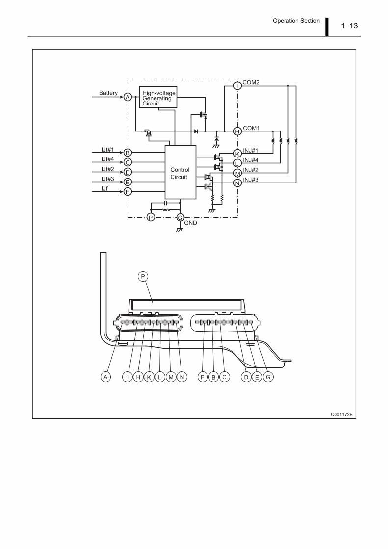
6.2 EDU (Electronic Driving Unit)
(1) 2AD-FHV
• An actuation energy-switching signal (input terminal "IJen") has been added to the EDU.
During only idle speed operation, a signal is sent to the EDU switching the injector to low energy actuation. As a result, noise reduction
at idle speed is achieved.
• The shape of the EDU connector has changed.
101 MPX1 A/C Amplifier, Other 119 IREL ECU Relay
102 IMI Immobilizer Input 120 IGSW Ignition Switch
103 IMO Immobilizer Output 121 MREL Main Relay and A/F Relay
104 - 122 TRC+ VSC, TRC ECU
105 STA Starter Relay 123 ENG+ VSC, TRC ECU
106 - 124 VPA2 Accelerator Position Sensor (Sub)
107 - 125 VPA Accelerator Position Sensor (Main)
108 TACH Meter 126 CCS Cruise Control Switch
109 - 127 PSP PS Pressure Sensor
110 - 128 WFSE DLC3
111 +B Battery + Main Relay 129 SIL DLC3
112 NEO VSC, TRC ECU 130 TRC- VSC, TRC ECU
113 EOM Immobilizer 131 ENG- VSC, TRC ECU
114 GREL Glow Plug Relay 132 EPA2 Accelerator Position Sensor (Earth)
115 - 133 EPA Accelerator Position Sensor (Earth)
116 - 134 VCP2 Accelerator Position Sensor (Power Supply)
117 W Warning Light135 VCPA
Accelerator Position Sensor (Power Supply)
118 TC Check Connector
No. Code Terminal Description No. Code Terminal Description

Operation Section1–12
(2) 2AD-FTV
• The discharge valve wiring has been deleted from the EDU wiring diagram.
Operation Section1–13

Operation Section1–14
7. FUEL INJECTION TIMING CONTROL
7.1 OutlineAfter injection has been introduced in addition to the injection pattern and control timing. As a result, a reduction in PM as well as
combustion noise is realized.
7.2 Injection Pattern
(1) 2AD-FHV
(2) 2AD-FTV
Operation Section1–15
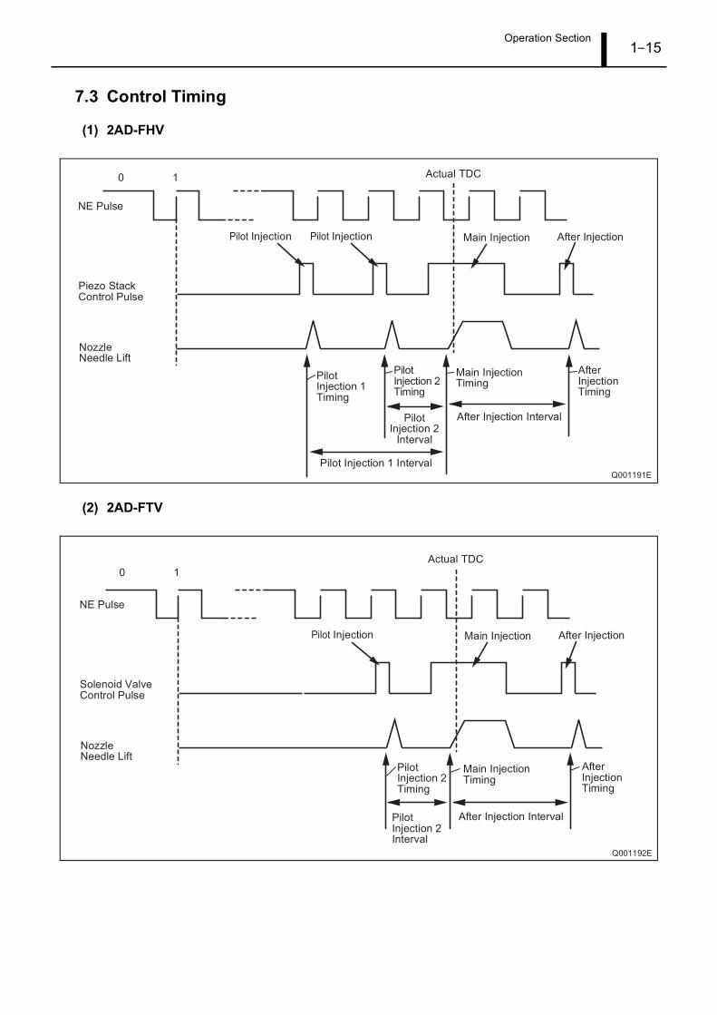
7.3 Control Timing
(1) 2AD-FHV
(2) 2AD-FTV

Operation Section1–16
8. DIAGNOSTIC TROUBLE CODES (DTC)
8.1 About the Codes Shown in the TableDiagnostic trouble codes (SAE codes) that utilize the STT (Intelligent Tester II) are displayed as output codes.
If multiple DTCs are output, they are shown in order starting with the lowest number
8.2 Diagnosis Trouble Code Table
< NOTE >
*1 : 2AD-FHV Only*2 : 2AD-FTV Only
DTC Code
(SAE code)Detection Item Trouble Area
P0031*1 Oxygen (A/F) Sensor Heater Control CircuitLow (Bank 1 Sensor 1)
• Open in A/F sensor heater circuit• A/F sensor heater• A/F sensor heater relay• Engine ECU
P0032*1 Oxygen (A/F) Sensor Heater Circuit High(Bank 1 Sensor 1)
P0045 Turbocharger / Supercharger Boost ControlSolenoid Circuit / Open
• VRV• Open or short in VRV circuit• Engine ECU
P0087 Rail System Pressure - Too low • Open or short in fuel pressure sensor circuit• Fuel pressure sensor• Engine ECU
P0088 Rail System Pressure - Too High • Supply pump (suction control valve)• Rail assembly (pressure discharge valve)*1
• Pressure limiter*2
• Short in supply pump (suction control valve) circuit• Engine ECU
P0093 Fuel System Leak Detected - large Leak • Fuel line between supply pump and rail• Fuel line between rail and each injector• Supply pump• Rail• Injectors• Pressure discharge valve*1
• Pressure limiter*2
• Open or short in EDU circuit (P0200 set simultaneously)• Open or short in injector circuit• EDU (P0200 set simultaneously)• Engine ECU
P0095 Intake Air Temperature Sensor 2 Circuit • Open or short in diesel turbo IAT sensor circuit• Diesel turbo IAT sensor• Engine ECU
P0097 Intake Air Temperature Sensor 2 Circuit Low
P0098 Intake Air Temperature Sensor 2 Circuit High
P0100 Mass or Volume Air Flow Circuit • Open or short tin mass air flow meter circuit•Mass air flow meter• Engine ECU

Operation Section1–17
P0101 Mass or Volume Air Flow Circuit Range /Performance Problem
•Mass air flow meter
P0102 Air Flow Meter Circuit Low Input • Open or short tin mass air flow meter circuit•Mass air flow meter• Engine ECU
P0103 Air Flow Meter Circuit High Input
P0105 Turbo Pressure / Atmospheric Pressure Cir-cuit
• Open or short in turbo pressure sensor circuit• Turbo pressure sensor• Turbocharger assembly• EGR valve assembly• Engine ECU
P0106 Turbo Pressure / Atmospheric Pressure Cir-cuit Range / Performance Problem
• Turbo pressure sensor
P0107 Turbo Pressure / Atmospheric Pressure Cir-cuit Low Input
• Open or short in turbo pressure sensor circuit• Turbo pressure sensor• Turbocharger assembly• EGR valve assembly• Engine ECU
P108 Turbo Pressure / Atmospheric Pressure Cir-cuit High Input
P0110 Intake Air Temperature Circuit • Open or short in IAT sensor circuit• IAT sensor• Engine ECU
P0112 Intake Air Temperature Circuit Low Input
P0113 Intake Air Temperature Circuit High Input
P0115 Coolant Temperature Circuit • Open or short in ECT sensor circuit• ECT sensor• Engine ECU
P0116 Coolant Temperature Circuit Range / Perfor-mance
• Coolant temperature sensor
P0117 Coolant Temperature Circuit Low Input • Open or short in ECT sensor circuit• ECT sensor• Engine ECU
P0118 Coolant Temperature Circuit High Input
P0120 Throttle Position Sensor / Switch "A" Circuit • Open or short in throttle position sensor circuit• Throttle position sensor• Engine ECU
P0122 Throttle Position Sensor / Switch "A" CircuitLow Input
• Throttle position sensor• Open or short in VLU circuit• Open in VC circuit• Engine ECU
P0123 Throttle Position Sensor / Switch "A" CircuitHigh Input
• Throttle position sensor• Open in E2 circuit• VC and VLU circuits are short-circuited• Engine ECU
P0168 Fuel Temperature Sensor Too High • Fuel temperature sensor
P0180 Fuel Temperature Sensor Circuit "A" Circuit
• Open or short in fuel temperature sensor circuit• Fuel temperature sensor• Engine ECU
P0182 Fuel Temperature Sensor Circuit "A" CircuitLow Input
P0183 Fuel Temperature Sensor Circuit "A" CircuitHigh Input
DTC Code
(SAE code)Detection Item Trouble Area

Operation Section1–18
P0190 Rail Pressure Sensor Circuit • Open or short in rail pressure sensor circuit• Rail pressure sensor• Engine ECU
P0192 Rail Pressure Sensor Circuit Low Input
P0193 Rail Pressure Sensor Circuit High Input
P0191*1 Rail Pressure Sensor Circuit Range / Perfor-mance
• Rail pressure sensor
P0200 Injector Circuit / Open • Open or short in EDU circuit• Injector• EDU• Engine ECU
P0234 Turbocharger / Supercharger Overboost Con-dition
• E-VRV for turbocharger• Open or short in VRV circuit• Turbocharger• Vacuum hose• EGR valve• Engine ECU
P0299 Turbocharger / Supercharger Underboost
P0335 Crankshaft Position Sensor "A" Circuit • Open or short in crankshaft position sensor circuit• Crankshaft position sensor• Crankshaft position sensor plate No.1• Engine ECU
P0339 Crankshaft Position Sensor "A" Circuit Inter-mittent
P0340 Cylinder Recognition Sensor "A" Circuit(Bank 1 or Single Sensor)
• Open or short bin Cylinder Recognition sensor circuit• Cylinder Recognition sensor• Pump drive shaft pulley• Engine ECU
P0400 Exhaust Gas Recirculation Flow • EGR valve stuck• EGR valve does not move smoothly• Open or short in E-VRV for EGR circuit• open or short in EGR valve position sensor circuit• EGR valve position sensor• Vacuum pump• Vacuum hose connection loose• Engine ECU
P0405 Exhaust Gas Recirculation Sensor "A" circuitLow
• Open or short in EGR valve position sensor circuit• EGR valve position sensor• Engine ECUP0406 Exhaust Gas Recirculation Sensor "A" circuit
High
P0488 Exhaust Gas Recirculation Throttle PositionControl Range / performance
• Throttle valve stuck• Throttle valve does not move smoothly• Open or short in throttle valve circuit• Open or short in throttle valve position sensor circuit• Throttle position sensor (built in diesel throttle body assembly)• Engine ECU
P0500 Vehicle Speed Sensor "A" • Open or short in speed sensor circuit• Speed sensor• Combination meter• Engine ECU
DTC Code
(SAE code)Detection Item Trouble Area

Operation Section1–19
P0504 Brake Switch "A" / "B" Correlation • Short in stop light switch signal circuit• Stop light switch• Engine ECU
P0516 Battery Temperature Sensor Circuit Low • Battery thermometer sensor• Short in battery thermometer sensor circuit• Engine ECU
P0517 Battery Temperature Sensor Circuit High
P0544*1 Exhaust Gas Temperature Sensor Circuit(Bank 1 Sensor 1) • Open or short in exhaust gas temperature sensor (on up stream)
circuit• Exhaust gas temperature sensor (on up stream)• Engine ECU
P545*1 Exhaust Gas Temperature Sensor Circuit Low(Bank 1 Sensor 1)
P546*1 Exhaust Gas Temperature Sensor Circuit High(Bank 1 Sensor 1)
P0560 System Voltage • Open in back-up power source circuit• Low battery voltage• Engine ECU
P0606 Engine ECU / PCM Processor• Engine ECU
P0607 Control Module Performance
P0617 Starter Relay Circuit High • Starter relay circuit• ignition switch• Engine ECU
P0627 Fuel Pump Control Circuit / Open • Open or short in suction control valve circuit• Suction control valve• Engine ECU
P1229 Fuel Pump System • Short in supply pump (suction control valve) circuit• Supply pump (suction control valve)• Engine ECU
P1238 Injector Malfunction Main • Injector• EDU (P0200 is set simultaneously)• Open or short in engine wire harness (P0200 is set
simultaneously)• Connector connection (P0200 is set simultaneously)• Compression pressure• Valve clearance
Related • Valve timing• Engine ECU
P1251 Turbocharger / Supercharger Overboost Con-dition (Too High)
• E-VRV for turbocharger• Open or short in VRV circuit• Turbocharger• Vacuum hose• EGR valve• Engine ECU
P1271*1 Fuel Regulator Circuit Malfunction (EDUDrive)
• Open or short in pressure discharge valve circuit• Open or short in pressure discharge valve itself• EDU• Engine ECU
DTC Code
(SAE code)Detection Item Trouble Area

Operation Section1–20
P1272*1 Fuel Regulator Circuit Malfunction • Open or short in pressure discharge valve circuit (P1271 is setsimultaneously)• Pressure discharge valve• Supply pump• Engine ECU
P1386*1 Injector for Exhaust Fuel Addition Main • Open or short in exhaust fuel addition injector circuit• Exhaust fuel addition injector• DPNR catalytic converter (Manifold converter sub-
assembly)
Replaced • Open in exhaust temperature sensor circuit• A/F sensor• Exhaust gas temperature sensor• Supply pump assembly•Mass air flow meter• Fuel leaks in exhaust fuel addition injector•Main injector• Cylinder compression pressure• Valve Clearance• Valve timing• Air intake system has blockages• Air intake system has leakage• Exhaust system has blockages• Exhaust system has leakage• EGR system has blockages• EGR system has leakage• Engine ECU
P1425*1 Differential Pressure Sensor Circuit • Open or short in differential pressure sensor circuit• Incorrect arrangement differential pressure sensor hose piping• Differential pressure sensor• Engine ECU
P1426*1 Differential Pressure Sensor Installation Error • Incorrect arrangement differential pressure sensor hose piping• Differential pressure sensor vacuum hose is clogged• Blockage in vacuum transmitting pipe sub-assembly• Differential pressure sensor• Engine ECU
P1427*1 Differential Pressure Sensor Circuit Low • Open or short in differential pressure sensor circuit• Incorrect arrangement differential pressure sensor hose piping• Differential pressure sensor• Engine ECU
P1428*1 Differential Pressure Sensor Circuit High
P1550 Battery Current Sensor Circuit • Short in battery current sensor circuit• Battery current sensor• Engine ECU
P1551 Battery Current Sensor Circuit Low
P1552 Battery Current Sensor Circuit High
P1601 EEPRPOM Error-Injector Correction Value,DPNR Thermal Degradation Record
• Engine ECU
P1602 Deterioration of Battery • Battery• Engine ECU back-up power source circuit
P1611 IC Circuit Malfunction • Engine ECU
DTC Code
(SAE code)Detection Item Trouble Area

Operation Section1–21
P1625*1 Idle Signal Transmitter Circuit • Open or short in idle control circuit• Engine ECU
P2002*1 Particulate Trap Efficiency Below Threshold(Bank 1)
• DPNR catalytic converter (Manifold converter sub-assembly)• Differential pressure sensor• Differential pressure sensor vacuum hose is clogged• Blockage in vacuum transmitting pipe sub-assembly• Exhaust gas temperature sensor• Exhaust gas leaks in TOYOTA D-CAT•Mass air flow meter• Engine ECU
P2031*1 Exhaust Gas Temperature Sensor Circuit(Bank 1 sensor 2)
• Open or short in exhaust gas temperature sensor (on down stream)• Exhaust gas temperature sensor (on down stream)• Engine ECU
P2032*1 Exhaust Gas Temperature Sensor Circuit Low(Bank 1 sensor 2)
P2033*1 Exhaust Gas Temperature Sensor Circuit High(Bank 1 sensor 2)
P2047*1 Reductant Injector Circuit / Open (Bank 1sensor 2)
• Open in exhaust fuel addition injector circuit• Exhaust fuel addition injector• Engine ECU
P2120 Accelerator Position Sensor / Switch “D” Cir-cuit
• Accelerator position sensor• Accelerator pedal• Accelerator pedal rod (arm) deformed• Engine ECU
P2121 Accelerator Position Sensor / Switch "D" Cir-cuit Range / Performance
• Accelerator position sensor circuit• Accelerator position sensor• Engine ECU
P2122 Accelerator Position Sensor / Switch "D" Cir-cuit Low Input
• Accelerator position sensor• Open in VCPA circuit• VPA circuit open or ground short• Accelerator pedal• Accelerator pedal rod (arm) deformed• Engine ECU
P2123 Accelerator Position Sensor / Switch "D" Cir-cuit High Input
• Accelerator position sensor• Open in EPA circuit• Accelerator pedal• Accelerator pedal rod (arm) deformed• Engine ECU
P2125 Accelerator Position Sensor / Switch "E" Cir-cuit
• Accelerator position sensor• Accelerator pedal• Accelerator pedal rod (arm) deformed• Engine ECU
P2127 Accelerator Position Sensor / Switch "E" Cir-cuit Low Input
• Accelerator position sensor• Open in VCP2 circuit• VPA2 circuit open or ground short• Accelerator pedal• Accelerator pedal rod (arm) deformed• Engine ECU
DTC Code
(SAE code)Detection Item Trouble Area

Operation Section1–22
P2128 Accelerator Position Sensor / Switch "E" Cir-cuit High Input
• Accelerator position sensor• Open in EPA2 circuit• Accelerator pedal• Accelerator pedal rod (arm) deformed• Engine ECU
P2138 Accelerator Position Sensor / Switch "D"/ "E"Voltage Correlation
• VPA and VPA2 circuit are short circuited• Accelerator position sensor• Accelerator pedal• Accelerator pedal rod (arm) deformed• Engine ECU
P2226 Atmospheric Pressure Circuit • Engine ECU
P2227 Atmospheric Pressure Circuit Range / Perfor-mance
P2228 Atmospheric Pressure Circuit low Input
P2229 Atmospheric Pressure Circuit High Input
P2237*1 Oxygen (A/F) Sensor Pumping Current Cir-cuit / Open (Bank 1 Sensor 1)
P2238*1 Oxygen (A/F) Sensor Pumping Current Cir-cuit Low (Bank 1 Sensor 1)
• Open or short in A/F sensor circuit• A/F sensor• A/F sensor heater• A/F sensor heater relay• A/F sensor heater and relay circuit• Engine ECU
P2239*1 Oxygen (A/F) Sensor Pumping Current Cir-cuit High (Bank 1 Sensor 1)
P2252*1 Oxygen (A/F) Sensor
P2253*1 Oxygen (A/F) Sensor
P2502 Charging System Voltage • Open in generator circuit• Generator• Drive belt• Engine ECU
DTC Code
(SAE code)Detection Item Trouble Area

Operation Section1–23
9. EXTERNAL WIRING DIAGRAM
9.1 ECU External wiring diagram
(1) 2AD-FHV

Operation Section1–24

Operation Section1–25
(2) 2AD-FTV

Operation Section1–26

DENSO CORPORATION Service Department
Edited and published by:
1-1 Showa-cho, Kariya, Aichi Prefecture, Japan
Published : May 2005