sertel electronics (pvt)ltd company profileserteltelser.com/admin12/fckeditor/_samples/php... ·...
TRANSCRIPT


SERTEL ELECTRONICS (PVT)LTD COMPANY PROFILE Dear Customer,
GPS Based time synchronization for various equipments of electrical / Instrumentation and computers.
Ref: - Power generation / Distribution
With reference to the above we are glad to inform you and also introduce ourselves that we are the manufacturers of time synchronization with an accuracy of 1 micro sec for time stamping. This time stamping will facilitate to identify the problem First caused / trip to another where by all contactors / Relays connected to cascading operation.
The salient features of the Synchronisation system which is as following: Master Clock and Slave Clock • Synchronised to GPS receiver (through satellite) • The slave clock can be connected to entire factory at various locations displaying the same • time through out the factory in terms of hour min & Sec. Time Synchronisation a) Electrical equipments Synchronisation Time synchronization synchronizing the electrical parameters such as event recorder, disturbance recorder, fault recorder and sequential event recorder. PLC’s, data acquisition system and other intelligence or RTU (remote terminal unit). b) Instrumentation Synchronisation Intelligence instrumentation PLC’S, DC’S, DAS, SCADA and other intelligence RTU’S c) Networking of Computers Various computers connected through landline with Ethernet synchronization by TCP/IP with 10 base T
or 100 base T with RJ 45 connector connected to the hub. We have also developed NTP server, NTP &
SNTP broadcast, NTP client to synchronies many computers.
We can give time synchronization output for various above equipment requirement with any
number of outputs such as Pulse, Potential free contact, IRIGB, RS232, RS485, BCD output also
IPPS, IPPM, IPPH and for computers TCP/IP, network time protocol synchronization with any
distance by using appropriate access such as line drivers, line receiver and also convectors
RS485/232 convertor for synchronization of time with an accuracy for 1 micro sec.

d) Frequency Monitoring
With an advantage of time reference of atomic clock we can generate frequency 50HZ as
standard frequency. This can be monitored with a raw mains frequency generated. These both frequency
are monitored, differentiated and integrated with respect to time of your choice with a period of
15,30,45,60 sec’s with an accuracy of 0.001HZ as a close monitoring for the healthy power of
generation/ distribution. This also can be monitored at various location of your plant similar to slave
clock of time display the frequency can be displayed at various locations with various character size of
the display.
e) Power MonitoringBy using appropriate transducers of watt transducer, var transducers (i.e.
active and reactive power) with an analog output of 4 - 20 MA can be converted into digital input and
monitored and can be displayed with respect to standard time and std frequency to indicate any
periodicity of active power and reactive power monitored and can be connected to computer for report
generation. WATT/VAR display to many location similar to slave clock with large display for
difference viewing.
f) Calibration for frequency With advantage of atomic clock time we convert various
frequencies and they are synthesized to give a very stable frequency available at all times
traceability to national standard can be used to calibrate a frequency based instruments such
as oscilloscope, wireless equipments, test and measuring instruments, time period recorders,
walky-talkies and other related frequency based equipments.The above five parameters can
be housed on a integrated panel to house to 19 inch rack with a power supply and battery
charger to give uninterrupt power for the functions of the above system. We here by SERTEL
manufacturers time and frequency indigenously and available at all times.We are enclosing
herewith our user’s list for your per usual and we are proud to associate with yourself and all
the systems we are glad to inform you Ourselves that our system are operating on all 24hrs,
365 days continuously with a rugged design for uninterrupt operation.

We are also enclosing our catalogue and other range of products, which we are manufacturing systems, and products. We are glad to associate with yourself on your projects, which would give us immense pleasure in executing to the satisfaction of both of us with an advantage of helping each other for mutual benefit. We request you to kindly send us your valuable enquiry and also register our name in your
vendor’s list. We are also glad to inform you that our products are approved by various consultant agencies to name important companies such as NTPC, Power grid, EIL, TCS, Tata power, BSES, Reliance power, GAIL and other consultancy also. In case if you can inform us as your consultant we are glad to take an approval to enable yourself to use our equipment for your projects. Yours faithfully, For SERTEL ELECTRONICS PVT. LTD (R. GOPALAN)-CHIEF EXECUTIVE (R.PRABHAKARAN –DIRECTOR.
SERTEL ELECTRONICS PVT. LTD 377, NEHRU NAGAR I CROSS STREET OLD MAHABALIPURAM ROAD CHENNAI 600 096 SOUTH INDIA Phone : 91-044- 23454060,.23454062, fax :- 23454061 Email : [email protected] (or) [email protected]

INDEX
Description
01. INTRODUCTION 02. SERTEL TIME SYNCH-SYSTEM
03. GPS ANTENNA 04. GPS RECEIVER 05. MASTER CLOCK A & B 06. MASTER CLOCK COMPARATOR 07. SIGNAL CONDITIONER-FOR ( PULSE OUTPUT) 08. SIGNAL CONDITIONER-FOR( RS 232 OUT PUT) 09. SIGNAL CONDITIONER-FOR ( IRIG B OUTPUT) 10. SIGNAL CONDITIONER-FOR (TCP-IP OUTPUT) 11. SIGNAL CONDITIONER-FOR (TCP-IP ON NTP OUTPUT) 12. SIGNAL CONDITIONER-FOR (BCD OUTPUT ) 13. BCD OUTPUT 37 PIN CONNECTION 14. POWER SUPPLY/BATTERY CHARGER A & B 15. DIODE ORING UNIT 16. DIGITAL SLAVE CLOCK 17. LINE DRIVER RECEIVER 18. SLAVE DISTRIBUTION AMP 19. SLAVE CLOCK BOOSTER UNIT
20. OPERATION 21. GPS / MASTER CLOCK & SLAVE CLOCK SYSTEM 22. FEATURES OF GPS RECEIVER
23. GPS RECEIVER LOCK/ UNLOCK 24. SERTEL MASTER CLOCK A& B INTENDED 25. MASTER CLOCK OPERATION PROCEDURE 26. TO SET IN DATE
27. TO SET IN TIME 28. REDUNDANT COMPARATOR UNIT
29. RS 232 (BH 232) OUTPUT FORMAT 30. RS 232 (SEPL 232) OUTPUT FORMAT 31. RS 232 (002 RS 232) OUTPUT FORMAT 32. V24 RS 232 FORMAT OUTPUT 33. SEPL RS 232 PC SYNCH- APPLICATION SOFTWARE 34. SEPL TCP-IP PC SYNCH- APPLICATION SOFTWARE 35. TCP-IP ON NTP INSTALLATION PROCEDURE 36. PULSE OUTPUT AND PFC OUTPUT 37. SELECTOR SWITCH SELECTION FOR PULSE/ PFC 38. THUMP WHEEL PULSE SELECTION PROCEDURE 39. IRIG B OUTPUT 40. DCF 77 OUTPUT 41. WARRANTY ****

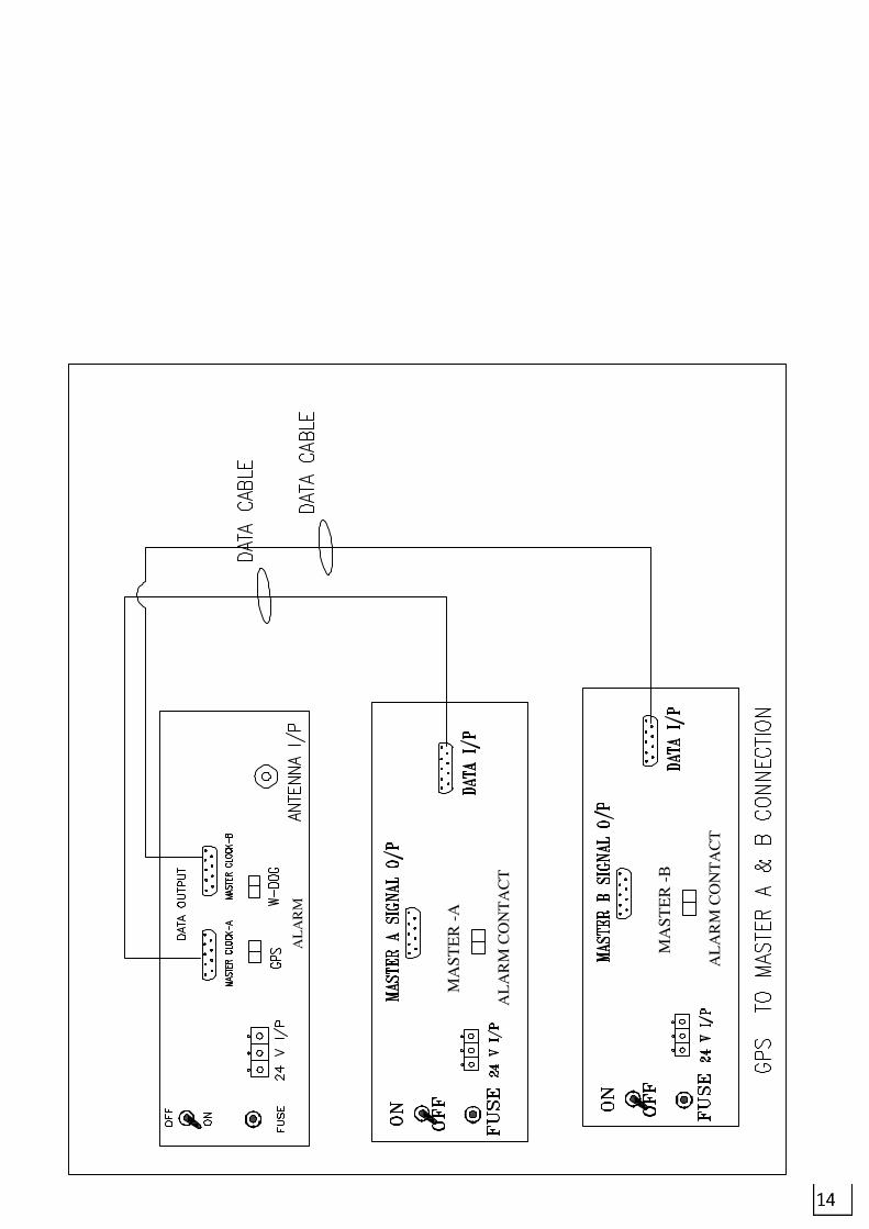
II WIRING DIAGRAM a) GPS Antenna fixing b) GPS Receiver connection c) GPS Receiver to MASTER CLOCK Connection e) Master A & B to comparator f) Comparator to signal conditioner g) Line driver /Receiver connection h) Power supply A & B and Diode Oring
i) Slave clock connection j) Signal booster with Slave clock connection
k) Supply voltage ferule connection
l) Contact output ferule connection
III Assembling lay out a) GPS Receiver b) Master A & B c) Comparator unit
d) RS 232 output unit e) Pulse output unit f) Signal conditioner IRIG B g) Diode oring unit h) Power supply IV PCB LAY OUT
V Circuit diagram VI TEST CERTIFICATE
*********************************************************

1
01 INTRODUCTION :
Global Positioning System is an absolute system to provide continuously the following to unlimited users. 3 dimensional Position Fixing (Latitude; Longitude & Altitude). Velocity ( Speed/Course ) measurement by detecting the Doppler shift in the radio signals emitted by GPS Satellites. Time Reference generation, utilizing the fact that the system is operated on a common
precise time base. GPS provides continuous worldwide coverage, 24 hours a day under Weather conditions Satellites distributed in 6 orbital planes (4 in each plane) spaced around the equator, pass over the earth at an altitude of approximately 20,000 kilometers. Each satellite has an orbital period of 12 side real hours (11 Hrs. and 58 Mnts. of civil time). A single satellite will orbit the earth twice a day, tracing the exact foot print path; but passing 4 minutes earlier than the day before. This ensures that at least 4 satellites will be in view at any time above any point on earth. Each GPS satellite bears an ultimate precision clock utilizing Rubidium-Cesium oscillation whose accuracy is comparable to Inter national Atomic Time. GPS Receiver collects the data from GPS Satellites and out puts a time base pulse (1PPS) every second in precise synchronisation with UTC/IST. Each 1PPS Pulse is accompanied by a Serial Data packet output ( A real time data comprising of Year, Month, Date, Hour, Minute and Second), which is a time stamp for that pulse. This output is utilised by Master Clock to synchronise its time with UTC/IST with a maximum uncertainity of 1 micro second and generate various outputs to synchronise any number of digital clock /microprocessor based systems. GPS system is sponsored and operated by US Department of Defence. Civilian access to the system is guaranteed through an agreement between US DOD and US DOT (Dept. of Transportation) and is subject to US Govt. Selective Availability (SA) policy
The Global Positioning system (GPS) is operated by the U.S.DOT and is subject
to U.S. Government selective availability (SA) Policy. SERTEL is not liable for the degradation by SA Users are expected to be familiar with system and make . Full use of it with their own responsibility.
SERTEL Electronics Pvt. Ltd reserves the right to make changes to our products any
specifications without notice.

2
02 SERTEL TIME SYNCHRONISATION SYSTEM
The system consists of 1. GPS ANTENNA/ WITH LOW LASS CABLE 2. GPS RECEIVER 3. MASTER CLOCK- A & B 4. REDUNDANT COMPARATOR CLOCK 5. SIGNAL CONDITIONER FOR a) RS 232 OUTPUT Signal conditioner
b) PULSE OUTPUT Signal Conditioner
c) IRIG B OUTPUT Signal Conditioner
d) TCP/IP OUTPUT Signal Conditioner
e) TCP/IP ON NTP OUTPUT Signal Conditioner
f) BCD OUTPUT Signal Conditioner
6. POWER SUPPLY -A & B / CHARGER 7. DIODE ORING UNIT 8. LINE DRIVER / RECEIVER 9. SLAVE CLOCK 10. SLAVE CLOCK SIGNAL BOOSTER
11. FULL WIRED PANEL
3
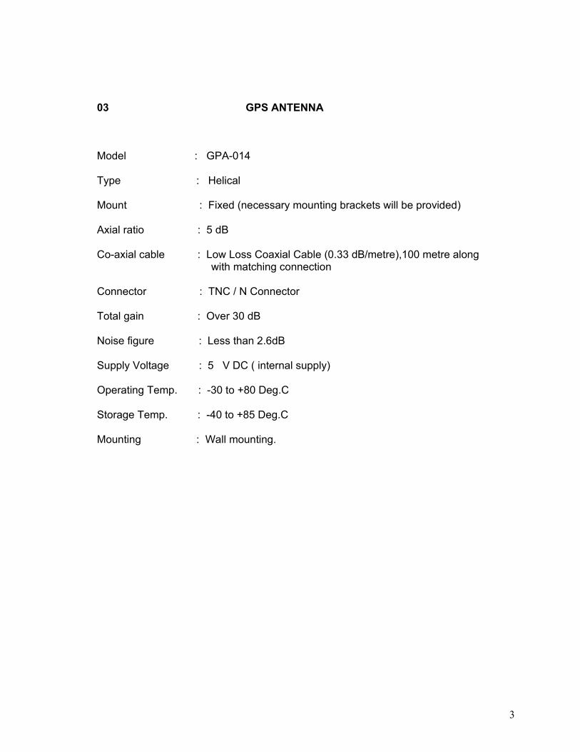
03 GPS ANTENNA
Model : GPA-014
Type : Helical Mount : Fixed (necessary mounting brackets will be provided) Axial ratio : 5 dB
Co-axial cable : Low Loss Coaxial Cable (0.33 dB/metre),100 metre along with matching connection
Connector : TNC / N Connector Total gain : Over 30 dB Noise figure : Less than 2.6dB Supply Voltage : 5 V DC ( internal supply) Operating Temp. : -30 to +80 Deg.C Storage Temp. : -40 to +85 Deg.C Mounting : Wall mounting.


5
04 GPS RECEIVER
Model : T-GPS-300 Type : Micro Controller type Display ; Backlit LCD display 24 Hours format
Time Accuracy : Better than 1 PPM Input ; 1575.14 MHz from Antenna
Input Connector : BNC
Output : RS 232 1 PPS OUTPUT to Redundant Master Clock
O/P Connectors : RS 232 / 1PPS – 9 Pin D Connector Front Panel : LCD Display To show Required Data And Status and number of satellites), valid data LED Back Panel : 24 V input connector , Fuse, On/Off switch , RS 232 / 1 PPS output, 9 Pin ‘D’ connector, Alarm contact terminal Supply Voltage : 24V Supply from redundant Diode Oring unit Environments : Temp. : 0-50 deg.cen RH : Up to 95% non condensing Mounting : To suit Standard 19” Rack System Dimension : 2U (H) X 484 (W) X 325 (D) `


7
05 MASTER CLOCK A & B-data
Model No. : T-MA-300
Type : Micro Controller based
Display : 7 segment LED(25mm size) to display TIME in HH,MM
and SS (24 Hrs. format) & in DD, MM and YY.
Time Reference : Oven Controlled Crystal Oscillator with stability of 1PPM temperature range of 0-50 deg.c
Time Accuracy : Better than 1PPM Time / Date Setting : Through Thumb wheel Switch Date / Time Toggle Switch Inputs : a) 1PPS } From RS232C } GPS Receiver I/P Connectors : 'D' connector 9 pin for RS232 and 1 PPS Outputs : Isolated output to Redundant comparator Clock
O/P Connectors : 9 pin D connector for Signal output to Redundant Comparator unit Supply Voltage : 24V supply from Diode Oring unit Environment : a) Temp. 0-50 Deg.C
b) RH 0-90% Non-condensing Front Panel : Display, Toggle S/W (Date / Time),Thumb wheel Stn.) Push Button S/W (ENTER),Lock S/W with Key Back Panel : ON / OFF Switch, Fuse, Power Supply Terminals Data output to comparator Terminal Contact output terminals. Panel Mounting : To suit Standard 19” Rack System
Dimension : 484mm (W) 2U (H) 325 mm(D)


9
06 REDUNDANT COMPARATOR UNIT-A & B Compressed in One Unit
Model No. : T-COM-300
Type : Micro Controller based
Display : No Display Only LED Indication
Time Reference :Oven Controlled Crystal Oscillator with stability of 1PPM temperature range of 0-50 deg.c
Time Accuracy :Better than 1PPM
Time / Date Setting :Automatically Synchronized with Master A or B Inputs :a) 1PPS }
b) RS232C } From Master Clock A & B I/P Connectors : 9 pin “D”connector for Master A & B input Outputs : a) RS 232 O/P to RS 232 Output Signal Conditioner b) S,M,H,D pulse to Pulse output Signal Conditioner c) IRIG B Output to IRIG B Signal Conditioner d) Data (RS232) Output to TCP/IP, TCP-IP ON NTP Output Signal Conditioner e) Differential Pulse to Slave Clock/ Slave Distribution amp f) Alarm Contact output for Master signal fail
O/P Connectors : a) 9 pin D connector for RS 232 o/p b) BNC for IRIG B O/P c) Mounting connector slave clock contact S,M,H,D,Pulse output and Alarm Output Supply Voltage : 24V DC supply from redundant Diode Oring unit. Environment : a) Temp. 0-50 Deg.C
b) RH 0-90% Non-condensing Front Panel : a) Master A & B input status INDICATION LED Indication b) Master A & B(comparator) output Indication LED c) Master A & B Input fail indication d) Signal output indication Back Panel : ON / OFF Switch, Fuse, Power Supply Terminals
All Input Output Contact terminals Panel Mounting : To suit Standard 19” Rack System
Dimension : 484mm (W) 3U (H) 325mm(D)


11
07 SIGNAL CONDITIONER- FOR PULSE OUT & PFC OUTPUT
Model No. : T-SC-300
Type : Micro Controller based Indication : LED INDICATOR FOR Pulse Input and Output
Inputs : S,M,H,D Pulse from Redundant Comparator Unit I/P Connectors : Pulse input Through Terminal connector
Outputs : a) PFC OUTPUT USER SELECTABLE BY SECOND,MINUTE,HOUR,DAY USING SELECTOR SWITCH. Or Fixed Pulse Output
Contact Duration 50msec(to vary from 20 to 999 msec) All pulses are isolated contact / Pulse output b) Pulse output for Second, Minute, Hour, Day Pulse Pulse Output Duration 50 msec
O/P Connectors : a) Mounting connector / BNC for all PFC contact output Pulse output Pulse contact duration 50 msec. Supply Voltage : 24 DC V supply from Redundant diode oring Environment : a) Temp. 0-50 Deg.C
b) RH 0-90% Non-condensing Front Panel : LED INDICATORS FOR Pulse Input & output LED Indicator. Back Panel : ON / OFF Switch, Fuse, Power Supply Terminals Pulse input terminal connector
PFC output terminal Pulse Output BNC / Mounting connector. PFC Contact output Selector Switch. Panel Mounting : To suit Standard 19” Rack System
Dimension : 484mm (W) 2U (H) 325 mm (D)


13
08 SIGNAL CONDITIONER FOR RS 232 output
Model No. : T-SC-300
Type : TIME FORMATE Display : LED INDICATORS FOR SIGNAL INPUT AND OUTPUTS
Inputs : RS 232 FROM Redundant Comparator Unit I/P Connectors : 9 PIN “D” (M) CONNECTOR Outputs : RS 232 Every minute / Every Second
O/P Connectors : RS 232 O/P 9 PIN “D” connectors . Supply Voltage : 24V supply from Diode Oring Unit Environment : a) Temp. 0-50 Deg.C
b) RH 0-90% Non-condensing Front Panel : LED INDICATORS FOR RS 232 I/P AND RS 232 OUTPUT Back Panel : ON / OFF Switch, Fuse, and Power Supply Terminals
1. RS 232 I/P CONNECTOR 2. RS 232 O/P CONNECTOR
Panel Mounting : To suit Standard 19” Rack System
Dimension : 484mm (W) 2U (H) 325 mm (D)


15
09 SIGNAL CONDITIONER FOR IRIG B (AM) output
Model No. : T-SC-300
Type : AM 1 Khz SIGNAL Indication : LED Indication for IRIG B input & output
Inputs : IRIG B signal FROM COMPARATOR CLOCK I/P Connectors : BNC (F) Connector for IRIG B Outputs : IRIG B (AM) O/P 1 Khz O/P Connectors : IRIG B (AM) O/P Through BNC connectors (F) . Supply Voltage : 24 DC V supply From Diode Oring Unit Environment : a) Temp. 0-50 Deg.C
b) RH 0-90% Non-condensing Front Panel : LED INDICATORS FOR IRIG B IN PUT AND IRIG B OUTPUT Back Panel : ON / OFF Switch, Fuse, Power Supply Terminals IRIG B I/P (BNC connector)
IRIG B OUTPUT BNC CONNECTOR Panel Mounting : To suit Standard 19” Rack System
Dimension : 484mm (W) 2U (H) 325 mm (D)


17
10 SIGNAL CONDITIONER FOR TCP-IP, output
Model No. : T-SC-300
Type : Network Time Synchronizing Display : LED Indication For Signal Input and Output
Inputs : RS 232 DATA From Redundant Comparator Unit I/P Connectors : 9 PIN “D” (M) Connector Outputs : TCP/IP Output Every Second to PC Synchronizing
O/P Connectors : RJ 45 Connectors . Supply Voltage : 24V supply from Diode Oring Unit Environment : a) Temp. 0-50 Deg.C
b) RH 0-90% Non-condensing Front Panel : Signal Input LED Signal Output LED and Power On LED Back Panel : ON / OFF Switch, Fuse, and Power Supply Terminals
1. RS 232 I/P 9 Pin D Connector
2. TCP_IP Output RJ 45 Connector
Panel Mounting : To suit Standard 19” Rack System
Dimension : 484mm (W) 2U (H) 325 mm (D)


19
11 SIGNAL CONDITIONER FOR TCP_IP ON NTP
Model No. : T-SC-300
Type : Network time Protocol to IP Based Synchronization Display : LED Indication for Signal Input and Signal Output
Inputs : RS 232 DATA From Redundant Comparator Unit I/P Connectors : 9 PIN “D” (M) Connector Outputs : TCP_IP ON NTP Every Second
O/P Connectors : RJ 45 Connector . Supply Voltage : 24V supply from Diode Oring Unit Environment : a) Temp. 0-50 Deg.C
b) RH 0-90% Non-condensing Front Panel : LED Indication for Signal Input LED and Signal Output LED Back Panel : ON / OFF Switch, Fuse, and Power Supply Terminals
1. RS 232 DATA I/P 9 Pin D Connector
2. TCP-IP ON NTP Output RJ 45 CONNECTOR
Panel Mounting : To suit Standard 19” Rack System
Dimension : 484mm (W) 2U (H) 325 mm (D)


21
12 SIGNAL CONDITIONER FOR BCD OUTPUT
Model No ; T-CON-300 Type : Micro controller Based Input Signal : Signal from Comparator unit Output Signal : BCD Output Input Connector : BNC Connector Output Connector : 37 Pin D Connector Output From Instrument : SECOND,MINUTE,HOUR IN BCD FORMAT TTL level Parallel BCD output for HH: MM: SS To drive up to 2 mts Length. Modulation ratio : Adjustable 2 : 1 to 4 : 1 (2 V to 12V Level)
Front Panel : LED indication Supply Voltage : 24 V DC


23
13 PIN CONFIGRATION: 37 PIN D Connector PIN DETAILS O/P OUTPUT 01 HOUR LSB 02 HOUR LSB 03 HOUR LSB 04 HOUR LSB 05 HOUR MSB 06 HOUR MSB 07 HOUR MSB 08 HOUR MSB 09 NO CONNECTION 10 MINUTE LSB 11 MINUTE LSB 12 MINUTE LSB 2013 MINUTE LSB 14 MINUTE MSB 15 MINUTE MSB 16 MINUTE MSB 17 MINUTE MSB 18 NO CONNECTION 19 SECOND LSB 20 SECOND LSB 21 SECOND LSB 22 SECOND LSB 23 SECOND MSB 24 SECOND MSB 25 SECOND MSB 26 SECOND MSB 27 NO CONNECTION 28 GROUND -ve SUPPLY 29 GROUND -ve SUPPLY 30 ------------- ----------------- 31 ---------------- ------------------ 32 ---------------- ------------------- 33 ---------------- --------------- 34 ----------------- ------------------ 35 -------------- ------------------ 36 ----------------- --------------- 37 ------------- ----------------

24
14 POWER SUPPLY /BATTERY CHARGER UNIT-A & UNIT-B
Model No. : T-PSU-24 V Input : 230 +/-10% AC from mains or UPS 50Hz AC I/P connectors : Through AC filter Output : 24V DC 4 Amps Max. to system supply 26.5 V DC to BATTERY ( 6AMP max ) Connectors : 3way connectors for 24 V DC & 26.5 V DC for charging battery Environment : (a) Temp. : 0-80 deg.cen (b) RH : 0-90% Non-condensing Front Panel : AC ON DC ON CHARGER ON LED indicators Back Panel : (a) AC 230V Input Terminal (b) 24V output terminal to instrument supply ( c ) 26.5 V DC to battery charging terminal (d) AC ON / OFF , DC ON /OFF, charger ON/ OFF switch
(e) AC Fuse (4 Amp.) (f) DC fuse ( 2amp) (g) Charger Fuse ( 4 Amp.)
Mounting : Panel Mounting 19 “ rack Dimension : 484(W), 325 (D), 3U(H) The battery is on float charge and is maintained at fully charged value at all times as long as the mains power is available. In the event of power failure, the change over to the battery is automatic and instantaneous. This is achieved by a diode switch. A Power Line Filter revents EMI /RFI. Individual fuse protection for the battery charger and Power Supply. Without time delay to support GPS Receiver. Note ; If No Battery Charger in the order Charger Input Output Not Applicable


27
15. DIODE ORING UNIT
Model : T-PSU-24V Input : 24V DC X two Terminal Type : Redundant Power Comparator I/P connector : Input (1) terminal (+) (-) Input (2) terminal (+) (-) Current rating : 4 Amp. Max. Output : Isolated 24V DC Supply to Modules Front Panel : LED indicator Input 1on & 2 on Out put on Back Panel : 24VDC Input 1 terminal
Input 2 terminal Input switch (1 & 2) Input fuse (1 & 2) Output Terminal Output Switch Output Fuse
Mounting : Suitable 19” rack mounting Dimension : 3U (H) x 484 (W) x 325 (D) MM


29
16. DIGITAL SLAVE CLOCK : MODEL No. T-SL300-100-6D
TECHNICAL SPECIFICATIONS:
Display : HOUR, MINUTE & SECONDS in 24 Hrs format Display size : 300mm. 7 segment Red LED - 6 Digits. Input : Differential Pulse from Comparator unit Clock. Power Supply : 240/220/110V AC Supply or ( Customer Specification) Connection : Slave clocks are connected to Master Clock by
3 core copper Conductor. (Multi Drop System) Slave updation : Every second
Environments : a) Temperature : 0-60 Deg.C
b) RH : 0-90% non condensing Mounting : Wall Mounting Mounting. Dimensions : Width : 700mm, Ht : 200mm, Depth:110mm
In its simplest form the Slave Clock is a binary counter with display. The front end detects the leading edge of the pulse train sent by Comparator Unit and clears the counter. They
count the updating pulses transmitted by the Comparator unit and display the time.


31
17. LINE DRIVER / LINE RECEIVER INTRODUCTION
SERTEL Line Driver is a stand alone, reliable and easy to use device and occupies very little space . Computer / Instrument terminals are generally connected to mainframe installation through RS 232C Interface. Serial port (RS 232C) can support only upto 50 feet. Beyond this limit , Line Drivers are basically used to boost the data signals. FEATURES Specially designed power supply 100% optical isolation has been provided, both at input and output. Protection against cable short circuit. Surge and lighting protection to safe guard the instrument terminals.
Model No. : T-LD-300, T-LR-300 Type : Asynchronous Compatibility : RS 232 C Max. Baud rate : 9600 bps constant (non selectable) Error rate : Both input & output are optically isolated Front Panel : Signal indicator & ON/OFF Switch 9 pin D connector RS 232 input output connector Back Panel : Fuse Holder (500MA) 230 V ac input terminal Input : RS 232 C (BHEL DDC Format) Output : RS 232C Cable connection : See block diagram (Annexure) Output connection : 9 pin ‘D’ Connector (for system) Input Voltage : 230V AC both Line Driver & Line Receiver Temperature : 0-50 deg.cen RH : 0-90 deg.cen


33
18. SLAVE DISTRIBUTION AMPLIFIER
Model No. : T-SDA-300 Display : LED Indication
Input : Differential Pulse from Comparator / Master Clock Unit. Output : Amplified Diff Pulse 4 Nos (Provided for 4 Direction) Power Su-pply : 24V DC From Diode Oring Unit
Signal Amplification : Every second Environments : a) Temperature : 0-50 Deg.C
b) RH : 0-90% non condensing Mounting : 19: Rack Panel Mounting
Dimension : 2U (H) x 484 (W) x 325 (D) MM Note Slave Distribution amp work as a Signal Booster. This having Provision of 4 Direction Connection Facility with Isolated Output. If number of Slave Clock Connected with Slave Distribution Amplifier one will affect other outputs will Not affect.


35
19. SLAVE CLOCK SIGNAL BOOSTER UNIT
Model No. : T-SBU-300 Display : No Display
Input : Differential Pulse from Comparator/ Master Clock Unit. Power Su-pply : 230V AC 50 Hz Connection : Signal booster are connected to Slave clocks by 3
core copper Conductor. (MULTI DROP SYSTEM ).
Signal Amplification : Every second Environments : a) Temperature : 0-50 Deg.C
b) RH : 0-90% non condensing Mounting : Wall Mounting / Table Top Mounting Dimensions : Width : 125 mm
Height : 60 mm Depth : 155mm PRINCIPLE: Signal boosters are required only more then 10 Slave Clock connected or distance More then 300 Mts from Comparator unit Slave clock Signal Boosting is Required. Signal Booster Connection with slave clock by 3 core parallel connection

36
20. OPERATION INSTALLATION/COMMISSIONING GPS MASTER CLOCK SYSTEM
INSTALLATION OF SERTEL GPS Based MASTER & SLAVE CLOCK SYSTEM Make sure your power supply is in compliance with specification Make sure the connection of BATTERY. If applicable The GPS antenna is an active type its drawing power from GPS Receiver .
1. Fix the GPS Antenna fixing Bracket firmly ensuring that the antenna had unobstructed view of the sky
2. Mount the antenna on the vertical post using Antenna fixing pipe.
3. Connect the co-axial cable to the antenna and firmly fix the cable on the post
(Low Loss Cable) 4. If The Antenna Cable more then 50 mtrs Between 50th Meter connect Inline Amplifier 5. Install the GPS receiver
6. Connect power supply ensuring proper polarity
7. Switching ON, the 2X 240V AC/ 110/ 230V AC Power supply and conform POWER SUPPLY A & B Input on LED are glow. And Switch ON DC power supply conform 24V DC availability at terminal and (26.5V at BATTERY) Volt all are ok Tern Switch ON MAINS ON Switch . Now watch GPS Receiver first fixes its own position by receiving the navigation message from 4 satellites and thereafter continuously outputs 1 PPS in precise synchronization with UTC so long as the following conditions are meet.
a) UTC parameter is available b) After own position has been fixed by receiving 4 satellite, at least one satellite is
traced continuously.

37
8. The GPS Receiver internally controls its accuracy of time and will not output is
available as indicator by the glowing of GREEN LED in the front panel, its accuracy is within
+/- 1 msec, of UTC.
9. TTFF : The conditions and period of time from POWER ON to first fix are as follows
Conditions and period of time from Power on to first fix are as follows:
Power on Accuracy availability of Initial Setting
Validity TTFF
Conditions L/L Time Almanac Ephemeris Typical
Warm Shaft Within 1 Deg Within 10 Min 1 Month 4 Hrs 20 Sec.
Cold Start Within 1 Deg Within 30 min 1 Month N/A 45 Sec. Autonomous Start
N/A N/A N/A N/A 2 Min

38
21. GPS / MASTER CLOCK & SLAVE CLOCK SYSTEM .01 . GPS Antenna
Collects the signals transmitted by GPS satellites and transmit the data to the GPS Receiver for further processing through the low loss inter connecting cable.
02 . GPS Receiver A & B
Collects the signals from the GPS Antenna and generates 1 No of RS 232 and Pulse output (1 PPS) to synchronise the Master Clock.
03 Master Clock A & B
These are 2 Nos of separate highly stable electronic clock system with in built high stable Oven Controlled Crystal Oscillators as time reference. The Master Clocks are constantly monitored by the outputs signals of the GPS receiver to keep them in synchronism with the GPS Receiver / time.
The OCXOs used as time reference in these clocks are quite stable with an accuracy better than 1 PPM These clocks generate necessary time signals and feed them to Redundant Comparator Units A & B for further processing. An alarm contact to indicate the non-availability of synchronizing signals from the GPS unit is included in the clock system to provide visual indication of the failure status
04 Redundant Comparator Unit
Redundant comparator: This unit receives the time signal generated by Master Clock A and Master
Clock B. The comparator compares the received signals and gives the healthy signal as output. If any one master fails automatically it accepts the signal from other master clock without any time delay and gives output. The output of this comparator unit is connected to the respective signal conditioners.
05 The MASTER CLOCK Redundant Comparator Units generate the following outputs: 1. Differential Pulse outputs to drive Slave Clocks.
2. Alarm contacts to provide status alarm. 3. RS 232 Output (DDC format) 4. Pulse Output 5. IRIG B (AM) output. 6 . TCP IP Output 7. TCP ON NTP Output

39
06 Signal Conditioner Units
Separate Signal Conditioner Units are provided for RS232, Pulse output IRIG B outputs. TCP/IP Output and TCP-IP ON NTP Output These output are galvanically isolated. The pulse outputs are customer selectable.
07 power Supply / Battery Charger Unit
To establish total redundancy in the power supply/ Battery Charger arrangements 2 Power Supply Units (A&B) are provided. They generate 24VDC isolated outputs and 26.5V DC to Charge the Battery. The output of the power supply units A & B are compared by a Diode Oring Power Supply Comparator to ensure availability of 24VDC output at all time.
08 Slave Distribution amp and Signal Booster
Slave Distribution amp provided for Four Direction Slave Clock Connection. Diff Pulse (slave pulse) from Comparator to synchronies with Slave Distribution Amp To Amplify Incoming signal and multiple the incoming signal and give 4 output

40
22. FEATURES OF GPS RECEIVER
• Uninterrupted parallel 8 channel tracking
• Data Calculation using upto 8 GPS satellite for accuracy
• Fast GPS Satellite acquisition
• High accuracy of UTC +/- 100 nanosecond (2 σ) in fixed observation point SPS Mode (Standard Positioning Service using C/A Code System)
• Output stable 1 PPS (pulse per second) signal even when switching satellite due to processing of 8 satellite data)
• Precision leap second adjustment is performed automatically
• Specialized in time synchronization and clock calibration NOTE : With Standard Positioning Services the accuracy of GPS is 2 Drms (two times distance root main square error)
Horizontal Accuracy: 100 Mtrs. Vertical Accuracy: 146 Mtrs Time: +/- 100 nano seconds with respect to UTC time With selective availability these accuracies are degraded. With respect to time the degradation is approximately 300-500 nano seconds
23. GPS RECEIVER WITH SATELLITE LOCK / UNLOCK SERTEL provided satellite lock / unlock indication & Contact output. . Switch on the system the GPS LED Not glow This indication known as the GPS Receiver not locked with the satellite. Once the position fix Front Side LCD Display, No of SAT Shown 04 and Status in 04 the GREEN LED will Glow Continues This Indication known as satellite is locked with GPS Receiver. At the same time GPS lock contact Available at rear side

41
24. SERTEL Master Clock A & B is intended to
a) Display correct time at different locations Irrespective of distance / number.
b) Maintain time accuracy within ± 1 Seconds / day c) Provide tailor-made 7 segment LED display of HRS, MINTS and SECONDS in 24 Hours format. d) Keep the Master and Slave clocks in synchronization At any point of time. Via Comparator Unit e) Provide Time Related Signals as required by the customer. f) Provide outputs to synchronies other micro controller/Process. based digital clock system

42
25. OPERATION PROCEDURE MASTER CLOCK ( with out GPS Receiver Signal ) 1. Switch off the GPS Receiver 2. Wait for 15 minutes to ensure that the Oven Controlled Crystal Oscillator attains the Operating temperature and stabilizes its output frequency. 3. Set Date and Times using THUMBWHEEL SWITCH, DATE / TIME TOGGLE SWITCH and. ENTER PUSH BUTTON. The procedure is given below. 26. DATE SETTING PROCEDURE: - Insert the key in RESET LOCK and turn to ON Position - Set DATE / TIME TOGGLE S/W to DATE Position. - Set the DATE through THUMNBWHEEL SWITCH marked DD, MM, and YY. Example: D D M M Y Y 09-- MAR –2009 /-----------------------------------------------------\ | | 0 | 9 | 0 | 3 | 0 | 9 | \ ----------------------------------------------------/ - Enter the value by pressing the Enter push button

43
27. To Set TIME - Set the DATE/ TIME TOGGLE S/W to TIME POSITION. - Set the time through THUMBWHEEL SWITCH marked HH,MM,SS. Example; To set 10 HRS, 30 MNTS & 30 SECONDS /-------------------------------------------\ | -- | 1 | 0 | 3 | 0 | 3 | 0 | \-------------------------------------------/ -- H H M M S S -- Enter the Value by pressing the enter push button
After setting these, turn the RESET LOCK to OFF position and remove the key. This is to prevent inadvertent resetting of the clock when the enter push inadvertent resetting of the clock when the Enter push button s/w is accidentally pressed.
** Note Above procedure only discounting the GPS signal input to Master clock When GPS Receiver Connected With Master Clock
By entering Master clock Thump Wheel Setting. Time and Date Master clock not responding

44
28.
Redundant Comparator Unit
This Unit consists of 2 identical Redundant Comparator Modules connected to the outputs of GPS RECEIVER & Master Clocks A & B. The Redundant Units receive the time signals generated by the Master Clocks A & B Compares them to assess synchronization. If the time data of both clocks agree, the Redundant Comparator “A” generates the required outputs and Redundant Unit “B” Through fully Operate is Kept as Standby in case of mismatch. This status is indicated in the panel , Full redundancy is obtained as shown below.
01 . In case of non availability of Satellite signal; the built in oscillator of GPS receiver is used as time reference to update the GPS time system and give necessary time outputs to Master Clock.
02. In case of failure of any one Master Clock; the signal are automatically generated by the redundant clock.
03. In case of non functioning of both Master Clocks, the signals are fed directly from the GPS Receiver of the Redundant Unit. This provision is normally not required. Only in emergent case, this has to be activated by a manual switch available on the front panel.
04 T he Redundant Comparator Units generate the following outputs: a) Differential Pulse outputs to drive Slave Clocks.
c) Alarm contacts to provide status alarm. d) RS 232 (BHEL DDC Format) e) Pulse Output f) IRIG B (AM) output.

45
29 RS 232 OUTPUT FROM SERTEL SYSTEM ( BH 123 FORMAT) The GPS/Master Clock should send an ASCII string of length 18 bytes with time of day / date and control codes automatically in the format as described below : CHAR NO. MEANING 1 STX (Start of Text) 2 Status 3 Day of week 4 Tens of hours 5 Unit of hours 6 Tens of minutes 7 Units of minutes 8 Tens of seconds 9 Units of seconds 10 Tens of days 11 Units of days 12 Tens of months 13 Units of months 14 Tens of years 15 Units of years 16 CR (Carriage return) 17 LF ( line feed) 18 ETX (End of text Format of Day of Week field B7 B6 B5 B4 B3 B2 B1 B0 Day 0 1 1 0 0 0 0 1 Monday 0 1 1 0 0 0 1 0 Tuesday 0 1 1 0 0 0 1 1 Wednesday 0 1 1 0 0 1 0 0 Thursday 0 1 1 0 0 1 0 1 Friday 0 1 1 0 0 1 1 0 Saturday 0 1 1 0 0 1 1 1 Sunday Note 1. The RS 232 C Output is on pin 3 with respect to pin 5 of the D-type male connector
a) Baud rate as applicable (9600) b) Data length ,8 bits (8)
Parity nil 2. The data string is transmitted once every minute

46
30. RS 232 OUTPUT (SEPL 001 FORMAT)
SERTEL provide a serial asynchronous bi-directional data port . The serial data port is factory configured with RS 232 (standard) signal level. RS 232 output is compatible electrically and mechanically with the EIA standard RS 232C as described for data terminal equipment (DTE)
9 pin ‘D’ Connector (M) pin connections Pin Connections
1. ………… NC
2. ………….. NC
3. ………….. RS 232 output
4. …………. NC
5. …………. Ground
6. …………. NC
7. ………… NC
8. …………. NC
9. …………. NC
RS 232 output from SERTEL as follows :
Data transmission every second
$ 6 0 HH MM SS DD MM YY CR LF
STARTTING hour Second Month CARRIAGE
CHARACTER RETURN
minute Date Year LINE FEED
RS 232 output from SERTEL as
follows :
Level ……. ASCII
Data Length …… 8 bit
Baud rate ……..9600
Event ……. Nun
Stop bit …….. 1

47
31. RS 232 OUTPUT ( 002 FORMAT)
THL RS 232 OUTPUT RS 232 FORMAT BADURATE 2400 DATA BIT 7 PARITY EVEN STOP BIT 1 PIN Nos OUTPOT 1 NC 2 NC 3 RS 232 OUTPUT 4 NC 5 GROUND 6 NC 7 NC 8 NC 9 NC PROTOCAL : XXX ; XX ; XX ; XX ? ; XXXX CRLF Julian hour minute second year day

48
32. RS 232 OUTPUT ( V24 OUTPUT FORMAT ) RS 232 V24 is used to transmit the absolute time from the Master Clock System
The Format as follows;
Start Bit - 1
Definition bit - 8
Parity bit - even
Stop Bit - 2
Transmission Every Minute of seconds 02
Harpes
Designation Num-of Bytes Value
Delimiter 1 Constant hexadecimal value FF
Header 1 Constant hexadecimal value 01
State byte 1 See below
Start of transmission 1 Constant hexadecimal value 02
Day of the week 1 Value in BCD (0)= Monday to 07 = Sunday
Day in Month 1 Value in BCD (01 to 31)
Month 1 Value in BCD ( 01 to 12)
Year 1 Value in BCD ( 01 to 99 )
Hours 1 Value in BCD ( 00 to 23 )
Minutes 1 Value in BCD ( 00 to 59 )
Seconds 1 Value constant in BCD 02
End of transmission 1 Constant hexadecimal value 03
Sync byte 1 Constant hexadecimal value 16

49
Expo 90
Designation Num-of Bytes Value
Delimiter 1 Constant hexadecimal value FF
Header 1 Constant hexadecimal value 01
State byte 1 See below
Start of transmission 1 Constant hexadecimal value 02
Day of the week 1 Value in BCD (0)= Monday to 07 = Sunday
Year 1 Value in BCD ( 01 to 99 )
Month 1 Value in BCD ( 01 to 12)
Day of the month 1 Value in BCD ( 01 to 31 )
Hours 1 Value in BCD ( 00 to 23 )
Minutes 1 Value in BCD ( 00 to 59 )
Seconds 1 Value constant in BCD 02
End of transmission 1 Constant hexadecimal value 03
Sync byte 1 Constant hexadecimal value 16
The time message comprises a state byte ;
Value in hexadecimal Operation
00 Normal
01 Sync missing
02 Serious malfunction
Above RS 232 Output are Any One format or Customer Specified Format only
Applicable.

50
33.
RS 232 OUTPUT (SEPL 001 FORMAT) Time Synch with PC, Server Application Software installation procedure
Service Name: Sertel time synchronisation system Input: RS232 - Sertel Format OS Platform: WinNT/Win2000/Win2003/WinXP Synchronisation at: Every Minute Steps to follow ( to register a timesync service): --------------------------------------------------- 1. Copy RS232 folder into c:\ as (c:\RS232) 2. Click "start" 3. Goto "Run" and type "command" and click "OK" button 4. The MS-DOS Screen will display in front of you. 5. type c: then press enter 6. type cd\ then press enter 7. type cd RS232 then press enter 8. Now verify that you are in c:\RS232> 9. Now type "sc create timesync binpath= c:\RS232\rs232.exe" 10. type cd\ then press enter 11. type cd c:\winnt\system32 then press enter 12. Now verify that you are in c:\winnt\system32> 13. type "mmc services.msc" (in MS-DOS Prompt or "Run" Dialog box) 14. find "timesync" in services list and double click it. 15. Make it is as "automatic" in start up type 16. goto Log on tab and enable "Allow service to interact with desktop" if you like to have a display on desktop. 17. Apply the above settings and Start the service and see whether the display appears or not. 18. Restart your PC and check whether the service starts automatically or not. Note: Registering a service under Windows NT based PC's, will normally require a Administrator level access. So, before registering a service you are requested to have a administrator logon access (i.e Administrator Password) Sertel Electronics [email protected] or [email protected]

51
34. TIME SYNCHRONISATION TCP/IP OUTPUT PC SYNCH- THROUGH NET
TCP / IP PORT
Introduction The EAD connects serial devices to Ethernet network using the IP Protocol. The EAD connects serial devices through a TCP data channel connection to computers. Network protocol The EAD uses IP protocol for network communication. For network Connections to the serial port of TCP. Internet protocol (IP) address to identify an individual computer IP network must have a unique IP address Sample IP address 192.168.1.254 PORT NUMBER The EAD serial channel (port) can be associated with a specific TCP Port number . port number 3001(as a source port no)is reserved for IFD (internet Fax dialer) configuration
ertel Provided TCP/IP output This will synchronies More Number of PC Through RJ45 Connection. To Connect 100/10 BasT HUB from Main Hub to All PC To Synchronies With PC Install Software The Following Step to Install the Software

52
Service Name: Sertel time synchronisation system Input: TCP/IP - Sertel Format OS Platform: WinNT/Win2000/Win2003/WinXP Synchronisation at: User Selectable via syncip.ini Steps to follow ( to register a timesync service): ---------------------------------------------------
1. Copy TCPIP folder into c:\ as (c:\TCPIP) 2. Click "start" 3. Goto "Run" and type "command" and click "OK" button 4. The MS-DOS Screen will display in front of you. 5. type c: then press enter 6. type cd\ then press enter 7. type cd TCPIP then press enter 8. Now verify that you are in c:\TCPIP> 9. copy syncip.ini file to c:\winnt folder (MS-DOS Command "copy syncip.ini c:\winnt") 10. Now type "sc create timesync_ip binpath= c:\TCPIP\tcpserv.exe" 11. type cd\ then press enter 12. type cd c:\winnt\system32 then press enter 13. Now verify that you are in c:\winnt\system32> 14. type "mmc services.msc" (in MS-DOS Prompt or "Run" Dialog box) 15. find "timesync_ip" in services list and double click it. 16. Make it is as "automatic" in start up type 17. goto Log on tab and enable "Allow service to interact with desktop" if you like to have a display on desktop. 18. Apply the above settings and Start the service and see whether the display appears or not. 19. Restart your PC and check whether the service starts automatically or not.
Note: Registering a service under Windows NT based PC's, will normally require a Administrator level access. So, before registering a service you are requested to have a administrator logon access (i.e Administrator Password)
syncip.ini file contents: ------------------------
[Network]
Server IP Address=0 // Leave this as 0 for automatic server detection or //otherwise specify server IP address (default-0) [Sync] Sync Interval=0 // Synchronization Interval: 0-Every Second 1-Every Minute //2-Every 1/2Hour,3-Evey Hour

53
35. SERTEL NTP/SNTP Configuration Procedure
***************************************************************************** Service Name: Sertel time synchronization system ***************************************************************************** STEPS TO CHANGING IP ADDRESS:(windows ONLY) ------------------------------------------------------------ NOTE1:”SWITCH ON THE UNIT AND CONNECT THE ETHERNET CABLE WITH THE NTP UNIT”. NOTE2:”YOU SHOULD CHANGE YOUR SYSTEM IP ADDRESS RELATED TO OUR DEFAULT IP ADDRESS (192.168.1.254)”. NOTE3:”THEN ONLY YOU CAN ABLE TO CHANGE IP ADDRESS INSIDE NTP UNIT”.
Click START at the bottom left corner of the desktop.
Click Run.

54
You have to type "telnet 192.168.1.254" and click ok.
It will show ts7200 login: here you have to type "admin" then press enter button. It will show password: here you have to type "ntp" then press enter button.
Now you can see '$' symbol.

55
Now you should type the command "cd /etc/sysconfig" then press enter button.
Now you should type the command "vi ifcfg-eth0"then press enter button.

56
It will show IP address and subnet mask details.
Here you can see IPADDR=192.168.1.254 at the second line. Here you press down key to second line then press right (->) key to move cursor right side up to
end (IPADDR=192.168.1.254_). Now you press x button till (IPADDR=_) then stop pressing.

57
Now sertel's default IP address deleted. Now you enter " i " button once, then you press right (->) key once (this is for give 1 space
between numbers and letters). Now you type your IP address according to your requirement (Note: should not use any using IP
address in your network).
After type your new IP address press Esc button two times. Now you have to type ":wq"(colon wq) press Enter.

58
Now you can see '$' symbol. Now type, "reboot".
Now your ntp server IP addresses have been changed. NOTE4:"YOU SHOULD CHANGE YOUR SYSTEM DEFAULT IP ADDRESS" *****************************************************************************

59
STEPS TO SYNCHRONISE WITH (windows XP and windows 2003) SYSTEM: -----------------------------------------------------------------------------
Click "START" at the bottom left corner of the desktop then go to Run.
Type "regedit" then enter.
Click HKEY_LOCAL_MACHINE\SYSTEM\CurrentControlSet\Services\W32time\Time-Providers\Ntpclient. (root key for the time service).
Right click specialpollinterval and click modify and delete the value 604800 and type 3C.
Click KEY_LOCAL_MACHINE\SYSTEM\CurrentControlSet\Services\W32time\config (root key for the time service).

60
Right click MaxNegPhaseCorrection and click modify and delete the value 54000 and type ffffffff.
Right click MaxPosPhaseCorrection and click modify and delete the value 54000 and type ffffffff.
Right click Update Interval and delete the value 00057e40 and type 3C. **************
Right click the time at the right bottom corner.
Select Adjust date/time.

61
It will show date and time properties.
Now you have to select Internet Time. And you have to tick the option that Automatically synchronize with Internet Time Server.
Then you have to enter your new NTP server IP address inside the server box. Now you click Apply, then click Update Now option, then click ok. Now your system gets synchronized. Close the date and time window.
*****************************************************************************

62
STEPS TO SYNCHRONISE WITH (Other than windows XP) SYSTEM:
You have to use net time software for synchronizes your pc time. Double click NetTime-2b7.exe. Follow all instructions. It will store its services at START-All Programs- Net Time. More over it will store its icon at right bottom corner near time. Now you have to right click net time icon and select properties. Now you have to select settings. Here you have to enter your NTP server address and you have to select SNTP. Here you have option for update intervals etc. According to your wish you can enter your values
and give "ok". Now it will show warning. Here you click "NO". Now your pc time get synchronized.
***************************************************************************** STEPS TO SYNCHRONISE WITH (Linux) SYSTEMS: -----------------------------------------------------------------------------
In DOS mode type "ntpdate -u server address". In graphics mode double click at time, tick Automatically synchronized with NTP server
option. Enter your NTP server address click Update Now. And give ok. Your system gets synchronized.
*****************************************************************************

63
36. PULSE OUTPUT AND PFC OUTPUT SERTEL provided Contact pulse output from Signal conditioner for 1 PPS, 1PPM , 1
PPH ,1PPD. ( 5 Sec, ½ H Pulse output ) The Contact pulse outputs are fully isolated
outputs. All Contact pulse output are Programmable Output. Pulse Output Duration
20 msec to 1 second duration set by During engineering at site condition
Rear side of the Pulse Output Signal Conditioner, BNC Connector or Selector Switch With Terminal / BNC Connectors are provided for Pulse / PFC Output. Specified output like 1 PPS, 1PPM, 1PPH, 1PPD required user tap from required o/p Through BNC Connector. Pulse Signal Conditioner Rear Side Selector Switch or Thump wheel Provision Available please select the following procedure. 37. SELECTOR SWITCH SELECTION: For example (a) Selection of SECOND contact output Simply turn any one of selector knob to Sec location every Second one contact available At connector (b) Selection of Minute contact output Turn the knob to Min location every Minute conduct available at Connector (b) Selection of Hour Turn the knob to Hour location every Hour available at Connectors (c) Selection of Day Turn the knob at Day location every day (24TH hour available at Connectors

64
38. THUMP WHEEL PULSE SELECTION
PFC / PULSE FIELD PROGRAMMING PROCEDURE, • TURN-ON LOCK SWITCH, • SET RELAYS TO PROGRAM ON THUMBWHEEL • SELECT REQUIRED OUTPUT AS BELOW SETTING • TO REGISTER, ENTER THE PUSH SWITCH • RL 01 TO 10 THUMBWHEEL FOR RELAY SELECTION • PC 1 TO 5 PULSE DURATION SELECTION • TURN OF LOCK SWITCH. THUMBWHEEL PROGRAMING FOR PULSE SELECTION TABLE DURATION SELECTION RL-1 R L-2 R L-3 R L-4 R L-5 R L-6 R L-7 R L-8 R L-9 RL-10 SECOND
01 1
02 1
03 1
04 1
05 1
06 1
07 1
08 1
09 1
10 1
MINUTE
01 2
02 2
03 2
04 2
05 2
06 2
07 2
08 2
09 2
10 2
½ HOUR
01 3
02 3
03 3
04 3
05 3
06 3
07 3
08 3
09 3
10 3
HOUR
01 4
02 4
03 4
04 4
05 4
06 4
07 4
08 4
09 4
10 4
DAY
01 5
02 5
03 5
04 5
05 5
06 5
07 5
08 5
09 5
10 5
For example (d) Selection of SECOND in 1st Relay contact output
Simply turn RL Thumbwheel in 01 and PC in 1 Every Second Contact Available at 1Marked Output Connector
(b) Selection of MINUTE in 2 Relay contact output
Simply turn RL Thumbwheel in 02 and PC in 2 Every Minute Contact Available at 2Marked Output Connector
(e) Selection of ½ Hour Relay Contact at 3 Relay output
Simply turn RL Thumbwheel in 03 and PC in 3 Every ½ hour Contact Available at 3Marked Output Connector
(f) Selection of Hour at Relay Contact output at 07 output
Simply turn RL Thumbwheel in 07 and PC in 4 Every Hour Contact Available at 7Marked Output Connector
(g) Selection of Day at Relay Contact output at 05 output
Simply turn RL Thumbwheel in 05 and PC in 5 Every DAY Contact Available at 5Marked Output Connector
RELAY CONTACT OUTPUT & PULSE

65
39. IRIG- B INTRODUCTION
IRIG-B standard time format by telecommunication working group . Inter range
instrumentation group range commanders council describes IRIG-B it is available by
writing secretly range commanders council. White sand missile range new Mexico
880022.
The standard time format of IRIG-B Code were designed for us in missile , satellite and
space research programmers. Use of these code facilities efficient interchange of test
data Those formats are suitable for recording on magnetic tape oscillo graphics film
and for real time transmission in both automatic manual data reduction . IRIG-B from
the SERTEL
GPS / MASTER CLOCK system is suitable for remote display driving magnetic tape
recording and may other use. IRIG-B codes in the strip sense encode Universal Co-
ordinate Time (UTC) in 24 Hours format only not local time. Nonetheless this
instrument can encode UTC and IST time in 24 hours format.
The frame length of IRIG-B is 1 second long and contains 100 elements (pulse) each of
which starts every 10 milli second (unmodulated) and 1 Milli second (modulated) .
SERTEL GPS/MASTER CLOCK provide output of IRIG-B in amplitude modulated
signal(1Khz) output at rear panel of BNC Connectors. This will help us long distance
communication.

66
Format B Signal B000 The beginning of each 1.0 second time frame is identified by two consecutive 8.0 ms bits, Po and P1. The Leading edge of P1 is the on-time reference point for the succeeding Time Code words. Position identifiers, Po and P1 through P9 (8 ms duration) occur every 10th bit and 10ms before the leading edge of each succeeding 10 pps “on-time”bit

67
40. SERTEL DCF 77 Introduction
DCF time code (slow code, 1 bit/sec.) Minute pulses (time marks) Hour pulses (optional time marks, 1 second duration).
The time information corresponds to local time (UTC + programmed time shift). DCF time code : The DCF time code (as transmitted by the German DCF77 transmitter on 77.5 kHz) is a slow serial time code consisting of 60 bits, transmitted at the rate of 1 bit/s. It takes 1 minute to deliver the full code. This time code is handy for many types of applications and it is becoming widely-used in Europe. The coding is as follows : Bit rate : 1 bit/sec. Negative pulses, beginning on the second (open collector starts conducting).
Pulse duration 0.1 second = value "0" Pulse duration 0.2 second = value "1" No pulse at second 59 of every minute (---> minute identifier !)

68
The time information is coded as follows : Bits 0 - 14 : always=0; 15 : quality of radio-synchronization : good =1, bad =0; 16 : upcoming time change : normally=0, before time change=1; 17 : winter=0, summer=1; 18 : winter=1, summer=0; 19 : always=0; 20 : always=1; 21-27 : minute (of next minute); 28 : combines with bits 21-27 for even parity; 29-34 : hour; 35 : combines with bits 29-34 for even parity; 36-41 : day of the month; 42-44 : day of the week (Monday=1); 45-49 : month; 50-57 : year; 58 : combines with bits 36-57 for even parity. 59 : the pulse is missing (minute identifier).
By menu, the GPS unit may be programmed to stop delivering the DCF code when GPS synchronization is bad. Minute Pulses, Time Marks : Minute pulses duration gives following indication :
Length Indication
1 second Minute mark when GPS synchronization OK 2 seconds Minute mark when GPS synchronization NOT OK4 seconds Minute mark at the full hour (local time) 10 Seconds Minute mark at 24.00 o'clock (local time)

69
Geo-version : output 1 (DCF code or minute pulses) may be programmed to operate on the internal quartz time base only, without automatic corrections by GPS. GPS information is then obtained from output 2, and used for compensating the quartz oscillator drift. Output 2, "F. Code", open collector, max 35 VDC, 500 mA, with the following Ssgnals :
In normal operating mode (permanent receiver operation) : "Fast Code" time code format (specifications on request). This fast code is not available when an RS-232 or RS-485 format is used (menu selection).
Output 2 in low power mode (geo-version) : slow code, bits are synchronous with output 1, giving time comparison between internal time and GPS time. This code is useful together with the DCF code operating on the internal quartz time base : it allows to correct for the drift of the quartz time base. The coding is as follows : Slow code "Time comparison between internal time and GPS time, based on latest GPS Reading" (geo-version) : Bits 1 to 12 : milliseconds of GPS time at time T (BCD-coded : 4 bits for every digit). Bits 13 to 19 : seconds of GPS time at time T. Bits 21 to 41 : time T = time of the last GPS reading = bits 21 to 41 of output 1 when the last GPS reading as made (at the full minute). Bits 42 to 48 : minute of GPS time (local time) at time T. Bits 49 to 54 : hour of GPS time (local time) at time T. Bit 56=1 for normal high precision mode; =0 for power saving low precision mode. Bit 57=1 : DCF code synchronized when GPS available; =0 : DCF code on quartz time base.
OMEGAFACE code (option) : fast code compatible with OMEGAFACE code (repetition rate 1 code/minute, bit length 0.02 second, 1600 Hz modulation).

70
Output 3, current-loop (optional) : 20 mA current-loop output (passive). Voltage to be applied : 12 - 40 VDC. Minimal voltage at 20 mA : 9 V. 1=20mA, 0=4mA.). Same signals as output 1. Output 4, RS-232/RS-485 : output of time information in RS-232 ASCII format, 1200 Baud. 5 formats selectable by menu. Options : - 5 meter cable with RS-232 sub-D 9-pin connector. - RS-485 instead of RS-232. Pin allocation :
GND RS-232 output RS-485 output (option) RS-485 output (option) Vdd (+5V)
Time message formats : Legend : HH=hours; MM=minutes; SS=seconds; MIS=milliseconds; DD=day of month; d=day of week (Monday=1); DOY=day of year; mm=month; YY=year; s=status byte.
1. <STX>HH:MM DD.mm.YY0<ETX><BCC> Byte format : 1 start-bit, 7 data-bits, 1 parity-bit (even), 1 stop-bit. Repetition rate : 1 message every minute, beginning exactly on the minute. BCC : XOR over all bytes from H to ETX (even parity).
2. HH:MM:SS.MIS DD/mm/YY DOY d s<CRLF> Byte format : 1 start-bit, 8 data-bits, 1 stop-bit, no parity. Repetition rate : 1 message every minute, beginning exactly on the minutes. Status byte : normally=30H; leap year=31H; bad GPS synchronization=34H; leap year and bad GPS synchronisation=35H.
3. <STX>SSMMHHDDmmYYs<ETX> Attention : the order of the tens and units is inverted. The units come first, then the tens. Byte format : 8 data-bits, 1 stop-bit, no parity. Repetition rate : 1 message every minute, beginning on the minute. Status byte : bad GPS synchronization and winter time=31H; bad GPS synchronisation and summer time=33H; Good GPS synchronisation and winter time=35H; Good GPS synchronisation and summer time=37H.

71
4. <STX>/K/Y/Y/m/m/D/D/d/D/O/Y/H/H/M/M/S/S/s/<LRC><ETX> Byte format : 8 data-bits, 2 stop-bits, no parity. 0.5 ms time slot between the bytes. Repetition rate : 1 message every minute, ending exactly on the minute. K=N for standard time (winter); =S for daylight saving time (summer). Status byte=S when good GPS synchronisation; =' ' when bad GPS
synchronisation. LRC : parity byte, XOR over all bytes from "K" to "s".
5. YYmmDDHHMMSSd<CRLF> Byte format : 1 start-bit, 7 data-bits, 1 extra-bit, 1 stop-bit, no parity. Repetition rate : 1 message every minute, beginning on the minute.

72
41 . WARRANTY SERTEL GPS Receiver System is warranted against defects in material and workman-ship. For manpower and passive components (like switches, resistors) this warranty is for a period of 12 Months from the date of supply. Expendable items like LEDs, ICs, Transistors, Crystals and other active components are warranted only for a period of 3 months from the date of supply. The warranty for the items repaired / replaced shall not exceed the period for which the equipment was originally warranted.
The foregoing warranty excludes routine maintenance, and calibration. The warranty does not apply to defects resulting from improper or inadequate maintenance, unauthorized modification or misuse and operation of the product not in conformity with operation manual.
In case of any malfunction, please deliver the equipment to our works and collect the same after repairs. The equipment shall be dispatched to you after repairs provided the packing and forwarding charges are borne by you.
The invoice must be provided at the time of warranty service. AFTER SALES SERVICE
Each instrument has been subjected to strict quality control. Inspection prior to being shipped. However should any malfunction occur, please contact us.


5
5
4
4
3
3
2
2
1
1
D D
C C
B B
A A
<Doc> <RevCode>
AVR SECTION
B
2 5Saturday, June 05, 2004
Title
Size Document Number Rev
Date: Sheet of
PB0PB1PB2PB3PB4PB5PB6PB7
SW1SW2SW3SW4SW5SW6SW7SW8
SW9SW10SW11SW12SW13
SW14SW15SW16
PB0PB1PB2PB3PB4PB5PB6PB7
PB0PB1PB2PB3PB4PB5PB6PB7
PB0PB1PB2PB3PB4PB5PB6PB7
SW17SW18SW19SW20SW21SW22SW23SW24
SW25SW26SW27SW28SW29SW30SW31SW32
SW1SW2SW3SW4SW5SW6SW7SW8
SW9SW10SW11SW12SW13
SW14SW15SW16
SW17SW18SW19SW20SW21SW22SW23SW24
SW25SW26SW27SW28SW29SW30SW31SW32
AD0AD1AD2AD3AD4AD5AD6AD7
AD0AD1AD2AD3AD4AD5AD6AD7
SW5SW6SW7
SW2SW3
SW8
SW4
SW1
PB6
PB2
PB4
PB7
PB3
PB0
PB5
PB1
PC0PC1PC2PC3SW9SW10SW11SW12
T0T1
AIN0AIN1
SSMOS1MIS0
SCK
XTAL1XTAL2
RESET
A8A9A10A11A12A13A14A15
PC0
PC1
PC2
PC3
RXDTXDINT0INT1PD4PD5WRRD
RDWRA0A1
CS
T0T1
AIN0AIN1
SSMOS1MIS0
SCK
A13A14A15
CS
AD0AD1AD2AD3AD4AD5AD6AD7
A0A1
ALE
MRPLTCDTCU5
C8C9
C10C11
CP0CP1
MRMR
CP0
CP0
Q3MRMR
XTA1
D2
XTAL1
D2 D1
D1
XTAL1
CN19
VCC
VCC
VCC
VCC
VCC
VCC
VCC
VCC
VCC
VCC
C
SR5
SIP9
123456789
C
SR4
SIP9
123456789
U12
74LS245
23456789
191
1817161514131211
A1A2A3A4A5A6A7A8
GDIR
B1B2B3B4B5B6B7B8
U8
74LS245
23456789
191
1817161514131211
A1A2A3A4A5A6A7A8
GDIR
B1B2B3B4B5B6B7B8
U5
74LS245
23456789
191
1817161514131211
A1A2A3A4A5A6A7A8
GDIR
B1B2B3B4B5B6B7B8
U3
74LS245
23456789
191
1817161514131211
A1A2A3A4A5A6A7A8
GDIR
B1B2B3B4B5B6B7B8
U9
AT89C51
91819 29
30
31
12345678
2122232425262728
1011121314151617
3938373635343332
RSTXTAL2XTAL1 PSEN
ALE/PROG
EA/VPP
P1.0P1.1P1.2P1.3P1.4P1.5P1.6P1.7
P2.0/A8P2.1/A9
P2.2/A10P2.3/A11P2.4/A12P2.5/A13P2.6/A14P2.7/A15
P3.0/RXDP3.1/TXD
P3.2/INTOP3.3/INT1
P3.4/TOP3.5/T1
P3.6/WRP3.7/RD
P0.0/AD0P0.1/AD1P0.2/AD2P0.3/AD3P0.4/AD4P0.5/AD5P0.6/AD6P0.7/AD7
U1
82C55
3433323130292827
53698
356
432140393837
1819202122232425
1415161713121110
D0D1D2D3D4D5D6D7
RDWRA0A1RESETCS
PA0PA1PA2PA3PA4PA5PA6PA7
PB0PB1PB2PB3PB4PB5PB6PB7
PC0PC1PC2PC3PC4PC5PC6PC7
C
SR3
SIP9
123456789
C
SR2
SIP9
123456789
C
SR1
SIP9
123456789
U13A
74LS74
2
3
5
6
41
D
CLK
Q
Q
PR
CL
U13B
74LS74
12
11
9
8
1013
D
CLK
Q
Q
PR
CLU14A
74LS14
1 2
D1
D
12
R1R
C6C
U2
MAX232
138
1110
134526
129147
R1INR2INT1INT2IN
C+C1-C2+C2-V+V-
R1OUTR2OUTT1OUTT2OUT
U6
74LS138
123
645
15141312111097
ABC
G1G2AG2B
Y0Y1Y2Y3Y4Y5Y6Y7
U11
74LS373
3478
13141718
111
256912151619
D0D1D2D3D4D5D6D7
OCG
Q0Q1Q2Q3Q4Q5Q6Q7
U4
74LS192
151
109
54
1114
3267
1213
ABCD
UPDNLOADCLR
QAQBQCQD
COBO
C4C
C3C
C2C
C5C
C1
C
JP1
HEADER 3
123
JP2
HEADER 3
123
JP3
HEADER 3
123
JP4
HEADER 3
123
U10
74LS90
141
2367
129811
AB
R0(1)R0(2)R9(1)R9(2)
QAQBQCQD
U7
74LS90
141
2367
129811
AB
R0(1)R0(2)R9(1)R9(2)
QAQBQCQD

5
5
4
4
3
3
2
2
1
1
D D
C C
B B
A A
<Doc> <RevCode>
AVR SECTION
B
3 5Saturday, June 05, 2004
Title
Size Document Number Rev
Date: Sheet of
A8A9A10A11 Q8
Q9Q10
C7C8
C5C4
1TCU1TCD
C2
C3C12C1
2RTCU2RTCD
4TCU4TCD
CP1
5TCU5TCD
2TCD
2TCUPL1TCD
Q3
PLMR
PLMR
2TCU2TCD
PLMR
4TCU4TCD
3TCU3TCD
PLMR
5TCU5TCD
SW1 SW2SW3 SW4SW5 SW6SW7 SW8SW9 SW10SW11 SW12SW13 SW14SW15 SW16SW17 SW18SW19 SW20SW21 SW22SW23 SW24SW25 SW26SW27 SW28SW29 SW30SW31 SW32SW33 SW34
SW2_1 SW2_2SW2_3 SW2_4SW2_5 SW2_6SW2_7 SW2_8SW2_9 SW2_10SW2_11 SW2_12SW2_13 SW2_14
SW2_5
SW2_2SW2_4
SW2_6SW2_7
SW2_1SW2_2
C1
C4
C5
C6
C7
C8
C9
C10
C11
C2
C3
C14
VCC
VCC
VCC
JP6
HEADER 7x2/SM
1 23 45 67 89 1011 1213 14
JP7
HEADER 10X2
1 23 45 67 89 1011 1213 1415 1617 1819 20
R3R
R2R
R5
10E/5W
R4
R
U20
74LS192
151
109
54
1114
3267
1213
ABCD
UPDNLOADCLR
QAQBQCQD
COBO
U19
74LS192
151
109
54
1114
3267
1213
ABCD
UPDNLOADCLR
QAQBQCQD
COBO
U17
74LS192
151
109
54
1114
3267
1213
ABCD
UPDNLOADCLR
QAQBQCQD
COBO
U16
DIP14
1234567 8
910111213141
234567 8
910111213
VCC
D2
D
1 2
D4
D
1 2
D6
D
1 2
D8
D
1 2
D9
D
1 2
D10
D
1 2
D11
D
1 2
D12
D
1 2
D13
D
1 2
D14
D
1 2
D15
D
1 2
D16
D
1 2
D17
D
1 2
D18
D
1 2
D19
D
1 2
D20
D
1 2
D21
D
1 2
D22
D
1 2
U15
74LS192
151
109
54
1114
3267
1213
ABCD
UPDNLOADCLR
QAQBQCQD
COBO
D3
D
1 2
D5
D
1 2
D7
D
1 2
U18
74LS192
151
109
54
1114
3267
1213
ABCD
UPDNLOADCLR
QAQBQCQD
COBO
JP5
HEADER 17X2
1 23 45 67 89 1011 1213 1415 1617 1819 2021 2223 2425 2627 2829 3031 3233 34

5
5
4
4
3
3
2
2
1
1
D D
C C
B B
A A
<Doc> <RevCode>
AVR SECTION
B
4 5Saturday, June 05, 2004
Title
Size Document Number Rev
Date: Sheet of
S1/OP3
Q8
S1/OP2
Q9
S1/OP1
Q10
S1/OP6
Q10
Q11
S1/OP5
Q12
S1/OP4
C10 200MSEC
C12 RESET
C13 10MSEC
C1 1MS 1PPSI/P MR
+12V+12V
R9
R
R12
R
Q1
SL100
32
1
Q4
TIP122
32
1
R6
R
Q8
TIP122
32
1
U14C
74LS14
5 6
R20
R
R22
R
Q11
SL100
32
1
Q13
TIP122
32
1
R17
R
Q15
TIP122
32
1
U21C
74LS14
5 6
U14B
74LS14
3 4
U14E
74LS14
11 10
U14F
74LS14
13 12
U22A
74LS14
1 2
U21A
74LS14
1 2
U21B
74LS14
3 4
C11
CNP D23
D
12
R30R
U22B
74LS14
3 4
R26
R
R28
R
Q17
SL100
32
1
Q19
TIP122
32
1
R24
R
Q21
TIP122
32
1
U21E
74LS14
11 10
U22D
74LS14
9 8
C12
CNP D24
D
12
R31R
U22E
74LS14
11 10
U22C
74LS14
5 6
U22F
74LS14
13 12
C9CNP
C1010MF
Q5
SL100
32
1
R10
R
Q9
BC548
32
1
R15
R
R18
R
R11
R
R13
R
Q2
SL100
32
1
Q6
TIP122
32
1
R7
R
Q10
TIP122
32
1
U14D
74LS14
9 8
Q16
TIP122
32
1
R21
R
R19
R
R23
R
Q12
SL100
32
1
U21D
74LS14
9 8
Q14
TIP122
32
1
Q20
TIP122
32
1
U21F
74LS14
13 12
Q22
TIP122
32
1
R25
RQ18
SL100
32
1
R29
R
R27
R
C7CNP
C810MF
Q3
SL100
32
1
R8
R
Q7
BC548
32
1
R14
R
R16
R

5
5
4
4
3
3
2
2
1
1
D D
C C
B B
A A
<Doc> <RevCode>
AVR SECTION
B
5 5Saturday, June 05, 2004
Title
Size Document Number Rev
Date: Sheet of
X1
X2
X1
RESET
2RXD2TXD1MF
XTAL1
JRIPD4
T0T1AIN0AIN1SSMAS1MIS0SCK
JSI IRJG-B
10MSEC
Z1Y1
IRIG-B
10MHZ
1PPS
INT0INT1
IRJG-B
X1
IRS232 O/P
RS232 I/P
2RS232 O/P
1TXD
1RXD
TT1 I/P1
TT1 O/P
SL_OP1SL_OP2SL_OP3SL_OP4SL_OP5SL_OP62RXD
2TXD
XTAL1 RESET10MHZ O/P 1KHZ
1MS 200 MSEC10 MSECIRJG-B O/PIRJG-B TTL
SINE X1
1KHZ
X1
VCC
VCC
VCC
VCC
VCC
VCC
VCC
VCC
+12V VCC
VCC
VCC
JP13
HEADER 3
123
JP11
HEADER 3
123
U24D
74LS14
9 8
U24C
74LS14
5 6R40
R
C17
CNP
R38
R
R41R
U23
AT90S2313
145
20
1213141516171819
236789
11
RESETXTAL2XTAL1
VCC
PB0/AIN0PB1/AIN1
PB2PB3/OC1
PB4PB5/MOSIPB6/MISO
PB7/SCK
PD0/RXDPD1/TXDPD2/INTOPD3/INT1PD4/TOPD5/T1PD6/ICP
C20
CNP
C19
CNP
C18
CNP
R34
R
R32
R
U25
DIP14
1234567 8
910111213141
234567 8
910111213
VCC
U26
74LS244
2468
11131517
119
181614129753
1A11A21A31A42A12A22A32A4
1G2G
1Y11Y21Y31Y42Y12Y22Y32Y4
R35
R
C13
CNP
D25
D
1 2
R33
R
C16CNP
C14
CNP
C15CNP
R36
R
R37R
R39R
JP9
HEADER 8
12345678
U27
DIP14
1234567 8
910111213141
234567 8
910111213
VCC
JP15
HEADER 5
1 2 3 4 5
JP12
HEADER 10
12345678910
JP10
HEADER 10
12345678910
JP14
HEADER 10
12345678910
JP8
HEADER 10X2
1 23 45 67 89 1011 1213 1415 1617 1819 20
R42R
C26
C
VR3POT
13
2
C27
C
C23C
R47R
R52R
R48R
R49
R
R45
R
R43
R
+
-
U29
LM741
3
26
7 14 5
+
-
U28
LM741
3
26
7 14 5
VR1
POT
13
2
C21
C
R50
R
R46
R
R44
R
VR2
POT
13
2
R53
RC25
C
R51
R
C24
CNP
R54
R
C22
C
C29CNP
C28
C
U24A
74LS14
12
U24B
74LS14
34