sertel gps system - sertel electronics · master clock a & b ... 1pps level exactly matching...
TRANSCRIPT

No. 377, Nehru Nagar, Chennai, Tamil Nadu
600096 Ph: 044-23454060,61
www.serteltelser.com,www.sertelelectronics.com
SERTEL GPS SYSTEM
A Sertel Electronics Manual

Contents
About 2
Problem Statement 2
Details 2
Abstract 2
Test/Inspection Report 2
Introduction 3
Active GPS Receiver (T-GPS-300) 4
GPS Antenna (T-GPA-014) 6
GPS Receiver (T-GPS-300) 7
Master Clock A & B (T-MA-300) 9
Redundant Comparator Unit A & B (T-
COM-300) 11
Signal Conditioner1 14
Signal Conditioner 2 16
Signal Conditioner 3 17
SERTEL NTP/SNTP CONFIGURATION
18
TCP/IP OUTPUT 32
TIME SYNCHRONISATION TCP/IP
OUTPUT 33
Signal Conditioner 4 36
Signal Distribution Amplifier 37
Digital Slave Clock (T-SL-300-100-6D)
38
Power Supply Unit 39
Diode O-ring Unit 40
Slave Clock Signal Booster Unit 41
Line Driver / Line Receiver 41
Warranty 43
About
This document is the Operation &
Maintenance, Installation manual for Sertel
GPS / MASTER Clock.
Problem Statement
O & M Manual
Details
1) Installation Details
2) Settings details
Benefit 1
Sertel T-GPS-300 is a highly user-friendly
device. The operations are easy-to-
understand and completely simple for the
operator to handle. The system requires
absolutely less maintenance and has very
high MTBFs.
Abstract
Characteristics and technical details of
system & each output is Explained below.
Test/Inspection Report
Inspection Report
Introduction
The salient features of Sertel’s Synchronization system are as follows:
Master Clock and Slave Clock
• Synchronized to GPS receiver (through satellite)
• The slave clock can be connected to entire plant at various locations displaying the same
Various Time Synchronization equipments to which our outputs are compatible for time
synchronization
a) Electrical equipments Synchronization:
Event recorders, disturbance recorder, fault recorder and sequential event recorder.
PLC’s, data acquisition system and other intelligence or RTU (remote terminal unit).
b) Instrumentation Synchronization:
Intelligence instrumentation PLC’S, DCS, DAS, SCADA and other intelligence RTU’S.
c) Networking of Computers
d) Frequency Monitoring
e) Power Monitoring
f) Calibration for frequency

4
Active GPS Receiver (T-GPS-300)
A fundamental deficiency of any ephemeris extension system is unknown future
events. This is typically the issues faced by all GPS receivers. The receiver will not be able
to know about satellites that will have become unhealthy, have undergone a clock swap,
or have had a maneuver (change in position). This means that the GPS Receiver engine
might rarely mistake a wrong satellite position as the true satellite position. However,
provided that there are enough other good satellites, the Receiver algorithms will
eventually eliminate a defective orbit from the solution. Effectively two satellites are
enough for making this decision by the receiver. Any GPS receiver locking up on a GPS
satellite has to do a two-dimensional search for the signal.
The first dimension is time
The GPS signal structure for each satellite consists of a 1023 bit long
pseudo-random number (PRN) sequence sent at a rate of 1.023 megabits/sec,
i.e. the sequence repeats every millisecond. For this data acquisition, the receiver
needs to set an internal clock to the correct one of the 1023 possible time slots by
trying all possible values. Sertel’s GPS has NPL certified internal clock OCXOs which
maintain its timing accuracy of ns level. Most receivers stop and dwell at each of
the possible steps for a couple of milliseconds, i.e. the receiver take 1-2 seconds to
try all the possibilities.
The second dimension is frequency.
The receiver must correct for inaccuracies in the apparent Doppler frequency of
the satellite and "zero-beat" the signal. Usually a receiver's crystal oscillator may
be off by up to +/- 10 kHz or so, so there are 20ish frequency cells that have to be
tested. And this process must happen for all N satellites that are in use. So,
the acquisition process can be quite laborious depending on the sky view of the
antenna position.

5
The longer a receiver observes the sky the more satellites it will have seen. At the equator,
and with full sky view, approximately ten satellites will show up in a one hour window.
After four hours of observation approx.16 satellites (i.e. half the constellation), after 10
hours approx. 24 satellites (2/3rd of the constellation), and after approx. 16 hours the full
constellation will have been observed. Lower sky visibility reduces these figures. This
means any obstruction in line of sight of Antenna to the Receiver & the satellites. Further
away from the equator the numbers improve because the satellites can be seen twice a
day. E.g. at 47 degrees north the full constellation can be observed in approx. 12 hours
with full sky view.
The usual search strategy our receivers adopt to start at an oscillator frequency
predicted on the basis of
(a) What is current Receivers approximate position? (Based on either the last known
position or last sync position),
(b) Where are the satellites now and what is their apparent velocity (based on the
almanac data down linked from the satellite and stored in the receiver's
memory), and
(c) What is the best guess for the receiver's crystal oscillator error (based on the last
known error and the current temperature in case of OCXO). This is the reason
Sertel has its own OCXO which maintains a constant temperature through its oven
& helps reducing the error of crystal used substantially.
After the receiver "smells" a signal, it establishes two tracking loops
-- one is a phase-locked loop in the frequency domain and the other is a time-locked loop
in 1023 bit code space domain with the goal of tracking both the code and carrier phases
for that signal. Once it acquires lock on the first satellite it can start extracting data from
the GPS signals. From there on, after synchronization, timing accuracy is maintained at
1PPS level exactly matching the GPS epoch. Sertel’s GPS reception strategy is to start with
the highest satellites in the sky and try to get 2 satellites in lock.

6
After the first 2 are found, the receiver has a fairly complete story on the time/frequency
characteristics and it immediately opens up and looks for more satellites, and it uses
them after another 30-60 seconds (average 45 sec). This creates a completely healthy
environment to maintain a timing accuracy of the order of ‘ns’ level (certified by
NPL(India)). Sertel’s receivers have more physical channels, so they can do more parallel
searches requiring less overhead in terms of time.
Getting a lock on by the GPS receivers on the ground usually takes some time especially
where the receiver is in a moving vehicle or in dense urban areas. The initial time needed
for a GPS lock is usually dependent on how the GPS receiver starts. There are three types
of start - hot, warm and cold.
Summarizing,
GPS Antenna (T-GPA-014)
MODEL NO T-GPA-014
TYPE HELICAL
MOUNT FIXED(NECESSARY MOUNTING BRACKETS WILL BE PROVIDED)
AXIAL RATIO 5db
CO-AXIAL CABLE LOW LOSS CO-AXIAL CABLE(0.33db/meter), 100 METER ALONG WITH MATCHING CONNECTORS.
CONNECTOR TNC CONNECTOR
TOTAL GAIN OVER 30 db
NOISE FIGURE LESS THAN 2.6db
SUPPLY VOLTAGE 5V DC INTERNAL SUPPLY
OPERATING TEMPERATURE -30 TO + 80°C
STORAGE TEMPERATURE - 40 TO + 85°C
MOUNTING WALL MOUNTING

7
GPS Receiver (T-GPS-300)
Sertel’s GPS receiver Configuration is as follows
Numbers of channel 16 channels
Position-Fixing System All-In-View SPS (DGPS RTCM-SC104)
Frequency 1575.42 MHz
Tracking Capability 12 Satellites simultaneously including 1 WAAS supporting channel
Number of Parallel Searches 16
Protocol NMEA Type
WAAS Support 1 Channel
Uses DGPS and the function to deselect unhealthy satellites
GPS-Fix data Renewal Rate 1 Second
1PPS Output UTC-Synchronized (1 pulse/second)

8
Acquisition/Tracking Specifications
Initial Acquisition Time 8.4 Seconds Hot Start (Open Sky)
36 seconds Warm Start (Open Sky)
44.9 Seconds Cold Start (Open Sky)
Re-acquisition Time 2 Seconds
(-127dBm or stronger signal interrupted for 10 seconds or less)
Horizontal Accuracy (2drms) 5.6m
Vertical Accuracy (2drms) 7.3m
Power Supply
Supply Voltage / Current Voltage: 3.0 to 3.6 Vdc
Current: Max 72 mA at 3.6 Vdc
External Back-up power Voltage: 2.1 to 3.6 Vdc
Current: 200 uA when Vcc = 3.6 Vdc
10uA when Vcc = 0.0 Vdc
Ambient Conditions Operating temperature: -30°C - +80°C
Storage temperature: -40°C - +85°C
Dimensions 20.8 mm (w) x 33.8 (l) x 6.3 mm (h)
Mass 8g (0.2 oz)

9
Master Clock A & B (T-MA-300)
Highly stable electronic clock system with in-built high stable Oven Controlled
Crystal Oscillators as time reference. Master Clocks are constantly monitored by the
outputs signals from Active GPS receiver to keep them in synchronism with the GPS
Receiver / time. The reference 1 PPS is maintained in sync with the epoch pulse of GPS.
OCXOs used as time reference in these clocks are quite stable with accuracy better than 1
PPM. Summarizing the features of our Master Clock,

10
MASTER CLOCK A & B (T-MA-300)
MODEL NO T-MA-300
TYPE MICRO CONTROLLER BASED
DISPLAY 7 SEGMENT LED (25 mm SIZE) TO DISPLAY TIME IN HH, MM AND SS (24HRS FORMAT) & IN DD , MM AND YY
TIME REFERENCE OVEN CONTROLLED CRYSTAL OSCILLATOR WITH STABILITY OF 1 PPM TEMPERATURE RANGE OF 0 - 50°C
TIME ACCURACY BETTER THAN 1 PPM
TIME/DATE SETTING THROUGH THUMB WHEEL SWITCH DATE/TIME TOGGLE SWITCH
INPUTS a) 1 PPS { FROM RS232C } RECIVER
INPUT CONNECTORS D' CONNECTOR 9 PIN FOR RS232 AND 1 PPS
OUTPUTS ISOLATED OUTPUT TO GPS/ MASTERCLOCK
OUTPUT CONNECTORS 9 PIN D CONNECTOR FOR SIGNAL OUTPUT TO GPS/ MASTER CLOCK
SUPPLY VOLTAGE 24V SUPPLY FROM DIODE ORING UNIT
ENVIRONMENT a) TEMP 0 -50°C b) TH 0-90% NON-CONDENSING
DATE/TIME DISPLAY ,TOGGLE S/W(DATE/TIME) THUMB WHEEL STATION. PUSH BUTTON S/W (ENTER),LOCK S/W WITH KEY
BACK PANEL ON/OFF SWITCH, FUSE AND POWERSUPPLY TERMINALS DATAOUTPUT TO COMPARATOR TERMINAL CONTACT OUTPUT TERMINALS
PANEL MOUNTING TO SUIT STANDARD 19" RACK SYSTEM
DIMENSION 484mm (W) 2U (H) 325mm (D)
Operational Procedure for Master Clock
Master clock is the master time signal generator which receives time from T-GPS-300RT
and generates the necessary signals for time synchronization of other devices.
Operations
Master Clock Allows Settings of Time and Date by operator
• When Master Clock Locks with GPS, no manual setting of DATE/TIME is allowed.
• Manual settings is allowed only when GPS lock fails.

11
Procedure for manual time/date settings
Set Date and Time using
THUMBWHEEL STATION SWITCH,
DATE / TIME TOGGLE SWITCH
Procedure to Set Date
Insert the key in RESET LOCK and turn to ON Position
Set DATE / TIME TOGGLE S/W to DATE Position.
Set the DATE through THUMBWHEEL SWITCH marked DD, MM, and YY.
FORMAT: D D M M Y Y
To Set 09-- MAR –2009 please enter 09 03 09
Enter the value by pressing the Enter push button
Procedure to Set Time
Set the DATE/ TIME TOGGLE S/W to TIME POSITION.
Set the time through THUMBWHEEL SWITCH marked HH, MM, and SS.
Example: HH:MM:SS
To set 10 hrs, 30 mins & 30 Secs set 10:30:30
� Enter the Value by pressing the enter push button
� Push RESET LOCK to OFF position and remove the key. This prevents any accidental
setting after Operators Setting is done.
Redundant Comparator Unit A & B (T-COM-300)
This Unit consists of 2 identical Redundant Comparator Modules connected to the
outputs of Master Clocks A & B. The Redundant Units receive the time signals generated
by the Master Clocks A & B compares them to assess synchronization. If the time data of
both clocks agree, the Redundant Comparator “A” generates the required outputs and
Redundant Unit “B” Through fully Operate is kept as Standby in case of mismatch. This
status is indicated in the panel, Full redundancy is obtained as shown below.

12
1. In case of non availability of 1 PPS signal from GPS units; the built in oscillator of GPS
receiver is used as time reference to update the GPS time system and give necessary time
outputs to Master Clock.
2. In case of failure of any one Master Clock; the signal are automatically generated by
the redundant clock.
3. In case of non functioning of both Master Clocks, the signals are fed directly from the
GPS Receiver of the Redundant Unit. This provision is normally not required. Only in
emergent case, this has to be activated by a manual switch available on the front panel.
The Redundant Comparator Units generate the following outputs:
Differential Pulse outputs to drive Slave Clocks.
IRIG B (AM) Output.
Alarm contacts to provide status alarm.

13
Redundant Comparator
MODEL T-COM-300
TYPE MICRO CONTROLLER BASED
DISPLAY NO DISPLAY ONLY LED INDICATION
TIME REFERENCE OVEN CONTROLLED CRYSTAL OSCILLATOR WITH STABILITY OF 1PPM TEMPERATURE RANGE OF 0-50°C
TIME ACCURACY BETTER THAN 1PPM
TIME/DATE SETTING AUTOMATICALLY SYNCHRONIZED WITH MASTER A OR B
INPUTS DATA SIGNALS FROM MASTER CLOCK A & B
INPUT CONNECTORS 9 PIN “D”CONNECTOR FOR MASTER A & B INPUT
OUTPUTS
A) IRIG B OUTPUT FROM SIGNAL CONDITIONER B) RS 232 OUTPUT (PROVISION) C) PULSE OUTPUT(PROVISION) D) DIFFERENTIAL PULSE TO SLAVE CLOCK E) ALARM CONTACT OUTPUT FOR MASTER SIGNAL FAIL F) NTP/SNTP OUTPUT G) TCP/IP OUTPUT
OUTPUT CONNECTORS
A) 9 PIN D CONNECTOR FOR RS 232 O/P B) BNC FOR IRIG B OUTPUT C) MOUNTING CONNECTOR SLAVE CLOCK CONTACT S,M, PULSE OUTPUT D) RJ45 CONNECTOR FOR NTP/SNTP E) RJ45 CONNECTOR FOR TCP/IP OUTPUT F) BARRIER CONNECTOR FOR PULSE OUTPUT
SUPPLY VOLTAGE 24V DC SUPPLY FROM REDUNDANT DIODE ORING UNIT.
ENVIRONMENT A) TEMPERATURE. 0-50°C B) RH : 0-90% NON-CONDENSING
FRONT PANEL A) MASTER A & B INPUT STATUS INDICATION LED INDICATION B) MASTER A & B(COMPARATOR) OUTPUT INDICATION LED C) COMPARATOR A & B INPUT FAIL INDICATION D) SIGNAL OUTPUT INDICATION
BACK PANEL ON / OFF SWITCH, FUSE, POWER SUPPLY TERMINALS ALL INPUT OUTPUT CONTACT TERMINALS
PANEL MOUNTING TO SUIT STANDARD 19” RACK SYSTEM

14
Signal Conditioner1
IRIG- B OUTPUT
IRIG-B standard time format by telecommunication working group. Inter range
instrumentation group range commanders council describes IRIG-B it is available by
writing secretly range commanders council. White sand missile range New Mexico
880022.
The standard time formats of IRIG-B Code were designed for us in missile, satellite
and space research programmers. Use of these code facilities efficient interchange of test
data. Those formats are suitable for recording on magnetic tape oscillo graphics film and
for real time transmission in both automatic manual data reduction. IRIG-B from the
SERTEL GPS / MASTER CLOCK system is suitable for remote display driving magnetic tape
recording and may other use.
IRIG-B codes in the strip sense encode Universal Co-ordinate Time (UTC) in 24
Hours format only, not local time. Nonetheless this instrument can encode UTC and IST
time in 24 hours format.
The frame length of IRIG-B is 1 second long and contains 100 elements (pulse) each
of which starts every 10 millisecond (un modulated) and 1 millisecond (modulated).
SERTEL GPS/MASTER CLOCK provides output of IRIG-B in amplitude modulated signal (1
KHz) output at rear panel of BNC Connectors. This will help us long distance
communication.

15
SIGNAL CONDITIONER FOR IRIG B
MODEL NO T-SC-300
TYPE AM 1KHZ SIGNAL
INDICATION LED INDICATION FOR IRIG B INPUT & OUTPUT
INPUTS IRIG B SIGNAL FROM GPS/MASTER CLOCK UNIT
INPUT CONNECTORS BNC (F) CONNECTOR FOR IRIG B
OUTPUTS IRIG B (AM) OUTPUT 1KHZ
OUTPUT CONNECTORS IRIG B (AM) THROUGH BNC CONNECTORS (F)
SUPPLY VOLTAGE 24V DC SUPPLY FROM DIODE ORING UNIT
ENVIRONMENT a) TEMPERATURE : 0-50°C b) RH 0-90% NON CONDENSING
FRONT PANEL LED INDICATION FOR IRIG B INPUT & OUTPUT POWER ON
BACK PANEL ON/ OFF SWITCH, FUSE AND POWER SUPPLY TERMINALS IRIG B INPUT (BNC CONNECTOR) IRIG B OUTPUT BNC CONNECTOR
PANEL MOUNTING TO SUIT STANDARD 19" RACK SYSTEM
DIMENSION 484mm (W) 2U (H) 325 (D)

16
Signal Conditioner 2
RS 232 OUTPUT
SIGNAL CONDITIONER FOR RS 232
MODEL NO T-SC-300
TYPE TIME FORMAT
DISPLAY LED INDICATORS FOR SIGNAL INPUT AND OUTPUT
INPUTS RS 232 FROM REDUNDANT COMPARATOR UNIT
INPUT CONNECTORS 9 PIN “D” (M) CONNECTOR
OUTPUT RS 232 / RS 485 EVERY MINUTE/EVERY SECOND
OUTPUT CONNECTORS RS 232 O/P 9 PIN “D” CONNECTORS
SUPPLY VOLTAGE 24V SUPPLY FROM DIODE ORING UINT
ENVIRONMENT a) TEMPERATURE : 0-50°C b) RH : 0-90% NON-CONDENSING
FRONT PANEL LED INDICATORS FOR RS 232 INPUT AND RS 232 OUTPUT
BACK PANEL ON/OFF SWITCH,FUSE AND POWER SUPPLY TERMINALS RS232 INPUT CONNECTOR RS232 0UTPUT CONNECTOR
PANEL MOUNTING TO SUIT STANDARD 19" RACK SYSTEM
DIMENSION 484mm (W) 2U (H) 325 mm (D)
17
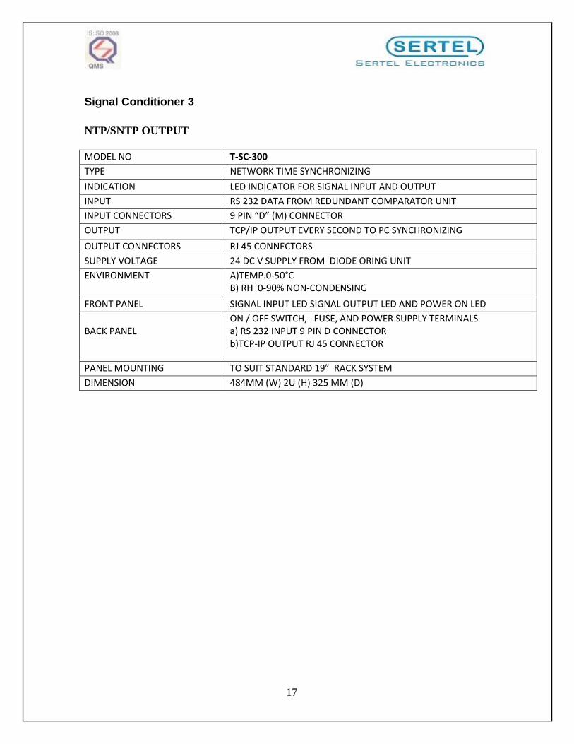
Signal Conditioner 3
NTP/SNTP OUTPUT
MODEL NO T-SC-300
TYPE NETWORK TIME SYNCHRONIZING
INDICATION LED INDICATOR FOR SIGNAL INPUT AND OUTPUT
INPUT RS 232 DATA FROM REDUNDANT COMPARATOR UNIT
INPUT CONNECTORS 9 PIN “D” (M) CONNECTOR
OUTPUT TCP/IP OUTPUT EVERY SECOND TO PC SYNCHRONIZING
OUTPUT CONNECTORS RJ 45 CONNECTORS
SUPPLY VOLTAGE 24 DC V SUPPLY FROM DIODE ORING UNIT
ENVIRONMENT A)TEMP.0-50°C B) RH 0-90% NON-CONDENSING
FRONT PANEL SIGNAL INPUT LED SIGNAL OUTPUT LED AND POWER ON LED
BACK PANEL
ON / OFF SWITCH, FUSE, AND POWER SUPPLY TERMINALS a) RS 232 INPUT 9 PIN D CONNECTOR b)TCP-IP OUTPUT RJ 45 CONNECTOR
PANEL MOUNTING TO SUIT STANDARD 19” RACK SYSTEM
DIMENSION 484MM (W) 2U (H) 325 MM (D)

18
SERTEL NTP/SNTP CONFIGURATION
Service Name: Sertel NTP/SNTP CONFIGURATION
FOLLOW THE BELOW STEPS FOR CONFIGURING NTP/SNTP.
The steps remain same for the operating system.
STEPS TO CHANGE IP ADDRESS:
NOTE1:”POWER ON THE UNIT AND PLUG THE ETHERNET CABLE WITH THE NTP
UNIT”.
NOTE2:”YOU SHOULD CHANGE YOUR SYSTEM IP ADDRESS RELATED TO OUR
DEFAULT
IP ADDRESS (192.168.1.254)”.
For example, 192.168.1.XXX
XXX- should be other than 254.
NOTE3: ”THEN ONLY YOU CAN ABLE TO CHANGE IP ADDRESS INSIDE NTP UNIT”.
STEP 1: Open internet explorer
STEP 2: Type web address with sertel’s default IP. (http://192.168.1.254/cgi-
bin/Login.sh)
STEP 3: It will show the Sertel Electronics home page.

19
STEP 4: Enter the Username as Admin and password as NTP ( password alphate are
Caps).

20
The next page will open like this, for using changing IP Configuration or default
setting.
STEP 5: Click Default. It will show default IP address

21
STEP 6: Click Submit. The changed IP address will appear within a few seconds in
another page.

22
STEP 7: Finally reboot the system. After reboot only it will sync with SERTEL NTP
client. We can ping with PC.
STEP 8: You can change the IP address as per your configuration.
For Example, As in below snapshot, we have entered the IP address as
192.168.16.54
Step 9: Click SUBMIT

23
Now the New IP address (192.168.16.54) changed successfully.

24
STEPS TO SYNCHRONISE WITH (windows XP and windows 2003) SYSTEM:
Click "START" at the bottom left corner of the desktop then go to run.

25
Type "regedit" then enter.
Click
HKEY_LOCAL_MACHINE\SYSTEM\CurrentControlSet\Services\W32tim
e\Time-Providers\Ntpclient. (Root key for the time service).
Right click special poll interval and click modify and delete the value
604800 and type 3C.
The above modifications should do for the following (Root key for the time
service).
Click
HKEY_LOCAL_MACHINE\SYSTEM\ControlSet001\Services\W
32time\Time- Providers\Ntpclient. (Root key for the time
service).

26
Click
HKEY_LOCAL_MACHINE\SYSTEM\ControlSet002\Services\W
32time\Time- Providers\Ntpclient. (Root key for the time
service).
*************************************************
Click
HKEY_LOCAL_MACHINE\SYSTEM\CurrentControlSet\Services\W3
2time\Time-Providers\Ntpserver. (Root key for the time service).
Right click input provider and click modify and delete the value
000000000 and type 2.
The above modifications should do for the following (Root key for the time
service).
Click
HKEY_LOCAL_MACHINE\SYSTEM\ControlSet001\Services\W2

27
time\Time- Providers\Ntpserver. (Root key for the time service).
Click
HKEY_LOCAL_MACHINE\SYSTEM\ControlSet002\Services\W3
2time\Time- Providers\Ntpserver. (Root key for the time
service).
CLICK
HKEY_LOCAL_MACHINE\SYSTEM\CurrentControlSet\Services\W
32time\config (root key for the time service).
Right click first name Announce Flags and delete the value 0000000a and
type 5.
Right click MaxNegPhaseCorrection and click modify and delete the value
54000 and type ffffffff.
Right click MaxPosPhaseCorrection and click modify and delete the value
54000 and type ffffffff.
Right click Update Interval and delete the value 00057e40 and type 3C.
The above modifications should do for the following (Root key for the time
service).
Click
KEY_LOCAL_MACHINE\SYSTEM\ControlSet001\Services\W32time\con
fig.

28
Click
KEY_LOCAL_MACHINE\SYSTEM\ControlSet002\Services\W32time\con
fig.
Right click the time at the right bottom corner.
Select Adjust date/time.
It will show date and time properties.

29
Now you have to select Internet Time. And you have to tick the option that
Automatically synchronize with Internet Time Server.
Then you have to enter your new NTP server IP address inside the server
box.

30
Now you click Apply, then click Update Now tab, then click ok.
Now your system gets synchronized.
Close the date and time window.
Note: if your ntp system is switched off and on, you have to wait for at
least 15minuts for synchronization after power on.
IF INTERNET TIME TAB IS NOT PRESENT OR IF YOU WANT TO ADD
MORE THAN ONE NTP SERVER FOR REDUNDANT SYNCHRONIZATION
Click
HKEY_LOCAL_MACHINE\SOFTWARE\MICROSOFT\WINDOWS\CU
RRENT VERSION\DATETIME\SERVER (root key for the time
services).
Here you can add NTP server address.
31
You have to select any ab string value name and right click and you have
to modify the address.
If the above name not available you have to right click it will show new.
Now you have click new and select string value and you have to name in
numbers ascending order.
Now you have to double click the ab string value name and type the NTP
server address.
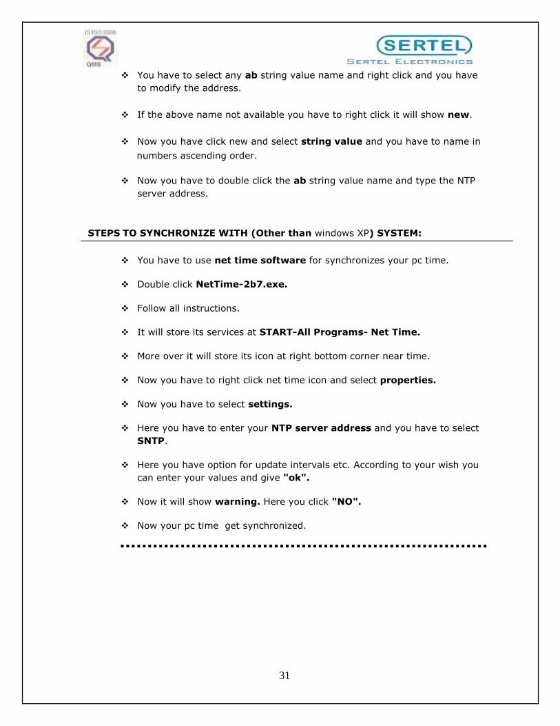
STEPS TO SYNCHRONIZE WITH (Other than windows XP) SYSTEM:
You have to use net time software for synchronizes your pc time.
Double click NetTime-2b7.exe.
Follow all instructions.
It will store its services at START-All Programs- Net Time.
More over it will store its icon at right bottom corner near time.
Now you have to right click net time icon and select properties.
Now you have to select settings.
Here you have to enter your NTP server address and you have to select
SNTP.
Here you have option for update intervals etc. According to your wish you
can enter your values and give "ok".
Now it will show warning. Here you click "NO".
Now your pc time get synchronized.

32
STEPS TO SYNCHRONISE WITH (Linux) SYSTEMS:
--------------------------------------------------------------- In DOS mode type "ntpdate -u server address".
You have to place the NTP server address at the configuration
file at ntp.conf.
In graphics mode double click at time, tick Automatically
synchronized with NTP. server option.
Enter your NTP server address click Update Now. And give ok.
Your system gets synchronized.
********************************************************
TCP/IP OUTPUT
MODEL NO T-SC-300
TYPE NETWORK TIME SYNCHRONIZING
INDICATION LED INDICATOR FOR SIGNAL INPUT AND OUTPUT
INPUT RS 232 DATA FROM REDUNDANT COMPARATOR UNIT
INPUT CONNECTORS 9 PIN “D” (M) CONNECTOR
OUTPUT TCP/IP OUTPUT EVERY SECOND TO PC SYNCHRONIZING
OUTPUT CONNECTORS RJ 45 CONNECTORS
SUPPLY VOLTAGE 24 DC V SUPPLY FROM DIODE ORING UNIT
ENVIRONMENT
A)TEMP.0-50°C
B) RH 0-90% NON-CONDENSING
FRONT PANEL SIGNAL INPUT LED SIGNAL OUTPUT LED AND POWER ON LED
BACK PANEL
ON / OFF SWITCH, FUSE, AND POWER SUPPLY TERMINALS
a) RS 232 INPUT 9 PIN D CONNECTOR
b)TCP-IP OUTPUT RJ 45 CONNECTOR
PANEL MOUNTING TO SUIT STANDARD 19” RACK SYSTEM
DIMENSION 484MM (W) 2U (H) 325 MM (D)

33
TIME SYNCHRONISATION TCP/IP OUTPUT
PC SYNCH-THROUGH NET TCP / IP PORT
Introduction
The EAD connects serial devices to Ethernet network using the IP Protocol. The EAD connects serial devices through a TCP data channel connection to computers.
Network protocol
The EAD uses IP protocol for network communication. For network Connections to the serial port of TCP.
Internet protocol (IP) address
To identify an individual computer IP network must have a unique IP address
Sample IP address 192.168.1.254

34
PORT NUMBER
The EAD serial channel (port) can be associated with a specific TCP Port number . port
number 3001(as a source port no)is reserved for IFD (internet Fax dialer) configuration
Sertel Provided TCP/IP output This will synchronies More Number of PC
Through RJ45 Connection. To Connect 100/10 BasT HUB from Main Hub to All
PC
To Synchronies with PC Install Software the following Step to Install the
Software
Service Name: Sertel time synchronization system
Input: TCP/IP - Sertel Format
OS Platform: WinNT/Win2000/Win2003/Win XP
Synchronization at: User Selectable via syncip.ini
Steps to follow ( to register a time sync service):
1. Copy TCPIP folder into c:\ as (c:\TCPIP) 2. Click "start"
3. Go to "Run" and type "command" and click "OK" button
4. The MS-DOS Screen will display in front of you.
5. Type c: then press enter
6. Type cd\ then press enter
7. Type cd TCPIP then press enter
8. Now verify that you are in c:\TCPIP>
9. Copy syncip.ini file to c:\winnt folder (MS-DOS Command "copy syncip.ini
c:\winnt")
10. Now type "sc create timesync_ip binpath= c:\TCPIP\tcpserv.exe"
11. Type cd\ then press enter
12. Type cd c:\winnt\system32 then press enter
13. Now verify that you are in c:\winnt\system32>
14. Type "mmc services.msc" (in MS-DOS Prompt or "Run" Dialog box)
35
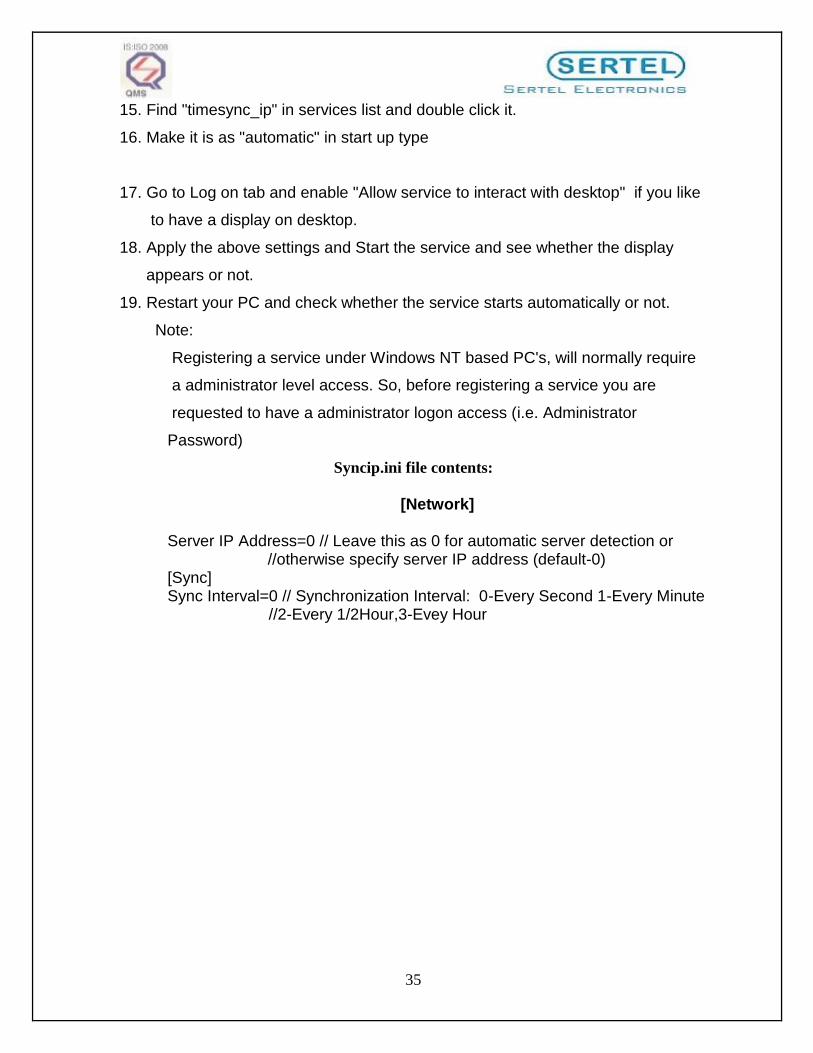
15. Find "timesync_ip" in services list and double click it.
16. Make it is as "automatic" in start up type
17. Go to Log on tab and enable "Allow service to interact with desktop" if you like
to have a display on desktop.
18. Apply the above settings and Start the service and see whether the display
appears or not.
19. Restart your PC and check whether the service starts automatically or not.
Note:
Registering a service under Windows NT based PC's, will normally require
a administrator level access. So, before registering a service you are
requested to have a administrator logon access (i.e. Administrator
Password)
Syncip.ini file contents:
[Network]
Server IP Address=0 // Leave this as 0 for automatic server detection or //otherwise specify server IP address (default-0) [Sync] Sync Interval=0 // Synchronization Interval: 0-Every Second 1-Every Minute //2-Every 1/2Hour,3-Evey Hour

36
Signal Conditioner 4
PULSE OUTPUT
MODEL NO T-SC-300
TYPE MICRO CONTROLLER BASED
INDICATION LED INDICATOR FOR PULSE INPUT AND OUTPUT
INPUT S,M GPULSE FROM REDUNDANT COMPARATOR UNIT
INPUT CONNECTORS PULSE INPUT THROUGH TERMINAL CONNECTOR
OUTPUT a) PFC OUTPUT USER SELECTABLE BY SECOND MINUTE USING
SELECTOR SWITCH. OR FIXED PULSE OUTPUT CONTACT DURATION
50MSEC (TO VARY FROM 20 TO 999 MSEC) ALL PULSE ARE ISOLATED
CONTACT / PULSE OUTPUT. B) PULSE OUTPUT FOR SECOND ,MINUTE
PULSE OUTPUT DURATION 50MSEC.
OUTPUT CONNECTORS A) MOUNTING CONNECTOR / BNC FOR ALL PFC CONTACT OUTPUT
PULSE OUTPUT ,PULSE OUTPUT CONTACT DURATION 50 MSEC
SUPPLY VOLTAGE 24 DC V SUPPLY FROM DIODE ORING UNIT
ENVIRONMENT A)TEMP.0-50°C
B) RH 0-90% NON-CONDENSING
FRONT PANEL LED INDICATOR FOR PULSE INPUT AND OUTPUT
BACK PANEL
ON/OFF SWITCH, FUSE,POWER SUPPLYTERMINALS PULSE INPUT
TERMINAL CONNECTOR PFC OUTPUT TERMINALS PULSE OUTPUT PFC
MOUNTING CONNECTOR . PFC CONTACT OUTPUT SELECTOR SWITCH
PANEL MOUNTING TO SUIT STANDARD 19” RACK SYSTEM
DIMENSION 484MM (W) 2U (H) 325 MM (D)

37
Signal Distribution Amplifier
MODEL NO. T-SDA-300
DISPLAY LED INDICATION
INPUT DIFFERENTIAL PULSE FROM COMPARATOR /
MASTER CLOCK UNIT.
OUTPUT AMPLIFIED DIFF PULSE 4 NOS
(PROVIDED FOR 4 DIRECTION)
POWER SU-PPLY 24V DC FROM DIODE ORING UNIT
SIGNAL
AMPLIFICATION
EVERY SECOND
ENVIRONMENTS A)0-50°C
B) RH : 0-90% NON-CONDENSING
MOUNTING 19: RACK PANEL MOUNTING
DIMENSION 2U (H) X 484 (W) X 325 (D) MM

38
Digital Slave Clock (T-SL-300-100-6D)
MODEL NO T-SL-300-100-6D
DISPLAY HOUR, MINUTE & SECONDS IN 24 HOURS FORMAT
DISPLAY SIZE 100 mm, 7 SEGMENT RED LED-6 DIGITS
INPUT DIFFERENTIAL PULSE FROM GPS/MASTER CLOCK UNIT
POWER SUPPLY 230V AC SUPPLY
CONNECTION SLAVE CLOCK ARE CONNECTED TO MASTER CLOCK BY
3 CORE COPPER CONDUCTORE . (MULTI DROP SYSTEM)
SLAVE UPDATION EVERY SECOND
ENVIRONMENTS a) TEMPERATURE :0 -60°C
b) RH : 0-90% NON CONDENSING
MOUNTING WALL MOUNTING
DIMENSIONS WIDTH: 700mm,Ht:200mm, DEPTH:110mm

39
Power Supply Unit
MODEL NO T-PSU-24V
INPUT 230±10% AC FROM MAINS OR UPS 50 HZ
AC INPUT CONNECTORS THROUGH AC FILTER
OUTPUT 24V DC 4 AMPS MAX . TO SYSTEM SUPPLY
CONNECTORS 3 WAY CONNECTORS FOR 24V DC
ENVIRONMENT a) TEMP : 0-80°C
B) RH : 0-90% NON -CONDENSING
FRONT PANEL AC ON DC ON LED INDICATORS
BACK PANEL a)AC 230V INPUT TERMINALS
b)24V OUTPUT TERMINAL TO INSTRUMENT SUPPLY
c) AC ON/OFF, DC ON/OFF, CHARGERON/OFF SWITCH
d)AC FUSE (4A ms)
e)DC FUSE (2A ms)
MOUNTING PANEL MOUNTING 19" RACK
DIMENSION 484(W), 325 (D), 3U (H).

40
Diode O-ring Unit
MODEL T-DO-300
INPUT 230V AC X TWO TERMINAL
TYPE REDUNDANT POWER COMPARATOR
INPUT CONNECTOR INPUT (1) TERMINAL (+) (-)
INPUT (2) TERMINAL (+) (-)
CURRENT RATING 4 Amp .MAX
OUTPUT ISOLATED 24V DC SUPPLY TO MODULES
FRONT PANEL LED INDICATOR
INPUT 1 ON & 2 ON
OUTPUT ON
BACK PANEL 24V DC INPUT 1 TERMINAL
INPUT 2 TERMINAL
INPUT SWITCH ( 1 & 2 )
INPUT FUSE ( 1& 2 )
OUTPUT TERMINAL
OUTPOT SWITCH
OUTPUT FUSE
MOUNTING SUITABLE 19" RACK MOUNTING
DIMENSION 3U (H) X 484 (W) X 325 (D) MM.
41
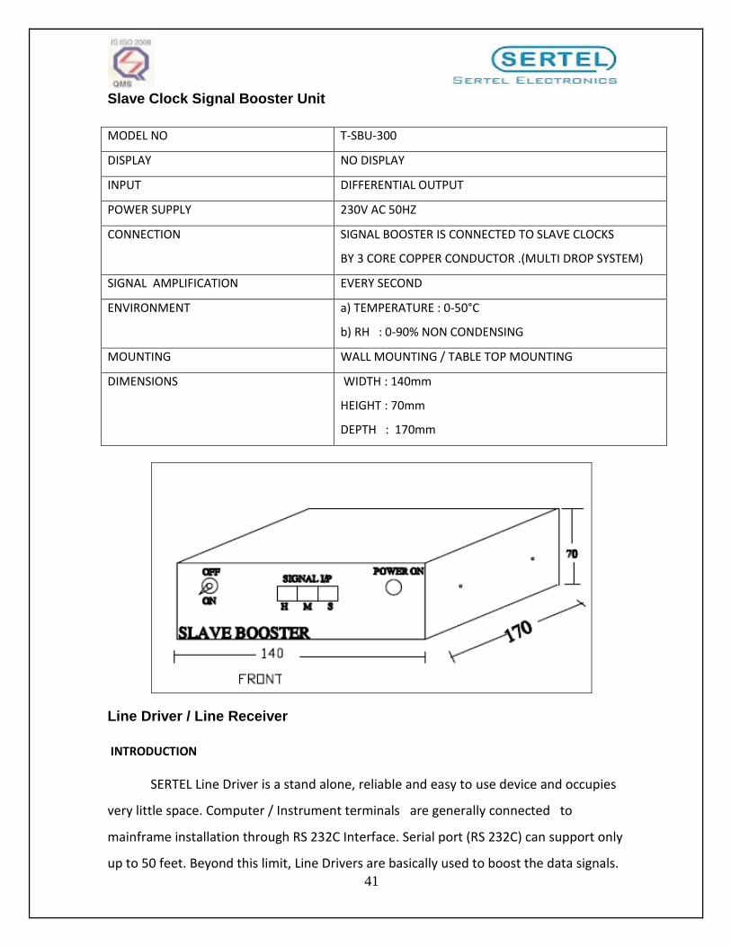
Slave Clock Signal Booster Unit
MODEL NO T-SBU-300
DISPLAY NO DISPLAY
INPUT DIFFERENTIAL OUTPUT
POWER SUPPLY 230V AC 50HZ
CONNECTION SIGNAL BOOSTER IS CONNECTED TO SLAVE CLOCKS
BY 3 CORE COPPER CONDUCTOR .(MULTI DROP SYSTEM)
SIGNAL AMPLIFICATION EVERY SECOND
ENVIRONMENT a) TEMPERATURE : 0-50°C
b) RH : 0-90% NON CONDENSING
MOUNTING WALL MOUNTING / TABLE TOP MOUNTING
DIMENSIONS WIDTH : 140mm
HEIGHT : 70mm
DEPTH : 170mm
Line Driver / Line Receiver
INTRODUCTION
SERTEL Line Driver is a stand alone, reliable and easy to use device and occupies
very little space. Computer / Instrument terminals are generally connected to
mainframe installation through RS 232C Interface. Serial port (RS 232C) can support only
up to 50 feet. Beyond this limit, Line Drivers are basically used to boost the data signals.

42
FEATURES
Specially designed power supply 100% optical isolation has been provided, both at input and output.
Protection against cable short circuit.
Surge and lighting protection to safe guard the instrument terminals. MODEL NO. T-LD-300, T-LR-300
TYPE ASYNCHRONOUS
COMPATIBILITY RS 232 C
MAX. BAUD RATE 9600 BPS CONSTANT (NON SELECTABLE)
ERROR RATE BOTH INPUT & OUTPUT ARE OPTICALLY ISOLATED
FRONT PANEL
SIGNAL INDICATOR & ON/OFF SWITCH 9 PIN D CONNECTOR RS 232 INPUT OUTPUT CONNECTOR
BACK PANEL FUSE HOLDER (500MA) 230 V AC INPUT TERMINAL
INPUT RS 232 C (BHEL DDC FORMAT)
OUTPUT RS 232C
CABLE CONNECTION SEE BLOCK DIAGRAM (ANNEXURE)
OUTPUT CONNECTION (FOR SYSTEM)
9 PIN ‘D’ CONNECTOR
INPUT VOLTAGE 230V AC BOTH LINE DRIVER & LINE RECEIVER
ENVIRONMENT TEMPERATURE : 0-50°C RH :0-90% NON-CONDENSING
43
Warranty
What does this warranty cover?
This Warranty applies to all Sertel’s products purchased from an authorized OEM
to the original purchaser for normal use and not for resale. SERTEL warrants that a
covered product is free from defects in materials and workmanship, with the exceptions
stated below.
How long does limited warranty coverage last?
This warranty lasts for 1 year from originally purchased date. A valid proof of
purchase may be required to prove eligibility. If you do not have a valid proof of purchase,
the warranty period will be measured from the date of sale from Sertel Electronics to the
OEM.
What does this warranty not cover?
The warranty does not cover damage resulting from commercial use, misuse,
accident, modification or alteration to hardware or software, tampering, unsuitable
physical or operating environment beyond product specifications, improper maintenance,
or failure caused by a product for which SERTEL Electronics is not responsible. There is no
warranty of uninterrupted or error-free operation. There is no warranty for product with
removed or altered identification labels.
Sertel does not provide any other warranties of any kind, including, but not
limited to, the implied warranties or conditions of merchantability and fitness for a
particular purpose. Some jurisdictions do not allow the limitation of implied warranties,
so this limitation may not apply to you.
SERTEL is not responsible for replacing the product which is not covered by this
warranty.

44
What must you do?
If you are having trouble with a product, before seeking warranty service, first
follow the troubleshooting procedures that SERTEL provides.
To obtain warranty service, please email [email protected]. All associated
transportation charges, duties and insurance in shipping the drive to our logistics center at
your cost. You should remove all personal information from the product prior to its return.
How is our liability limited?
Sertel and its affiliates, suppliers, distributors, and resellers are not liable for any of the
following:
1) third-party claims against you for damages
2) loss of, or damage to, your data; or
3) special, incidental, or indirect damages or for any economic consequential damages
(including lost profits or savings), even if informed of the possibility. Some jurisdictions do not
allow limitation of liability, incidental damages, or consequential damages, so the above
limitations may not apply to you.
AFTER SALES SERVICE Please contact [email protected] or [email protected] for further details.

45