series 3250 curtain wall - crl-arch · d. protect the materials after erection. ... steel anchors...
TRANSCRIPT
Phone: (800) 262-5151 • Fax: (866) 262-3299crlaurence.com • usalum.com • crl-arch.com
ALUMINUM
INSTALLATION INSTRUCTIONS
SERIES 3250 CURTAIN WALL
11M0168_REV_A

SERIES 3250 CURTAIN WALL
ALUMINUM02crlaurence.com | usalum.com
The following precautions are recommended to protect the material against damage. Following these precautions will help ensure early acceptance of your products and workmanship.
A. HANDLE CAREFULLY. AII aluminum materials at the job site must be stored in a safe place, well removed from possible damage by other trades. Cardboard wrapped or paper interleaved materials must be kept dry.
B. CHECK ARRIVING MATERIALS. Check for quantities and keep records of where various materials are stored.
C. KEEP MATERIALS AWAY FROM WATER, MUD, AND SPRAY. Prevent cement, plaster, or other materials from damaging the finish.
D. PROTECT THE MATERIALS AFTER ERECTION. Protect erected frame with polyethylene or canvas splatter screen. Cement, plaster, terrazzo, other alkaline solutions, and acid based materials used to clean masonry are harmful to the finish. If any of these materials come in contact with the aluminum, immediately remove with water and mild soap.
The rapidly changing technology within the architectural aluminum products industry demands that CRL U.S. Aluminum reserve the right to revise, discontinue or change any product line, specification or electronic media without prior written notice.
NOTE: Dimensions in parentheses ( ) are millimeters unless otherwise noted.
HANDLING, STORAGE, AND PROTECTION OF ALUMINUM

SERIES 3250 CURTAIN WALL
ALUMINUM03crlaurence.com | usalum.com
1. REVIEW CONTRACT DOCUMENTS. Check shop drawings, installation instructions, architectural drawings, and shippinglists to become thoroughly familiar with the project. The shop drawings take precedence and include specific details for theproject. Note any field verified notes on the shop drawings prior to installing. The installation instructions are of a generalnature and cover most conditions.
2. INSTALLATION. All materials are to be installed plumb, level, square, and true.
3. BENCH MARKS. All work should start from bench marks and/or column lines as established by the architectural drawingsand the general contractor with guaranteed accuracy. Working from these datum points and lines determine:
a) The plane of the wall in reference to offset lines provided on each floor.b) The finish floor lines in reference to bench marks on the outer building columns.c) Mullion spacing from both ends of masonry opening to prevent dimensional build-up of daylight opening.
4. STEEL ANCHORS. Steel anchors that weld to steel structure are normally line set before mullions are hung. Outstandingleg of anchors must be at 90 degrees to offset lines. Mullion space should be held to ±1/32" (0.8). Anchor clips vary per jobconditions. Follow approved shop drawings for size and location of clips.
5. FIELD WELDING. All field welding must be adequately shielded to avoid any splatter on glass or aluminum. Results willbe unsightly and/or structurally unsound. Advise general contractor and other trades accordingly. All field welds of steelanchors must receive touch-up paint (zinc chromate) to avoid rust.
6. SURROUNDING CONDITIONS. Make certain that construction which will receive your materials is in accordance with thecontract documents. If not, notify the general contractor in writing and resolve differences before proceeding with work.
7. ISOLATION OF ALUMINUM. Aluminum to be placed in direct contact with uncured masonry or incompatible materialsshould be isolated with a heavy coat of zinc chromate or bituminous paint.
8. SEALANTS. Sealants must be compatible with all materials with which they have contact, including other sealantsurfaces. Consult with sealant manufacturer for recommendations relative to joint size, shelf life, compatibility, cleaning,priming, tooling, adhesion, etc. It is the responsibility of the Glazing Contractor to submit a statement from the sealantmanufacturer indicating that glass and glazing materials have been tested for compatibility and adhesion with glazingsealants, and interpreting test results relative to material performance, including recommendations for primers andsubstrate preparation required to obtain adhesion. The chemical compatibility of all glazing materials and framing sealantswith each other and with like materials used in glass fabrication must be established. This is required on every project.
9. FASTENING. Within the body of these instructions "fastening" means any method of securing one part to anotheror to adjacent materials. Only those fasteners used within the system are specified in these instructions. Due to thevarying perimeter conditions and performance requirements, perimeter and anchor fasteners are not specified in theseinstructions. For perimeter and anchor fasteners refer to the shop drawings or consult the fastener supplier.
10. BUILDING CODES. Due to the diversity in state/provincial, local, and federal laws and codes that govern the designand application of architectural products, it is the responsibility of the individual architect, owner, and installer to assurethat products selected for use on projects comply with all the applicable building codes and laws. CRL U.S. Aluminumexercises no control over the use or application of its products, glazing materials, and operating hardware, and assumesno responsibility thereof.
11. EXPANSION JOlNTS. Expansion joints and perimeter seals shown In these instructions and in the shop drawings areshown at normal size. Actual dimensions may vary due to perimeter conditions and/or difference in metal temperaturebetween the time of fabrication and the time of installation. Gaps between expansion members should be based ontemperature at time of installation.
12. WATER HOSE TEST. As a representative amount of the wall has been glazed (500 square feet or 46.5 m2) a water hosetest should be conducted in accordance with AAMA 501.2 specifications to check the installation. On all jobs the hosetest should be repeated every 500 square feet (46.5 m2) during the glazing operation.
13. COORDINATION WITH OTHER TRADES. Coordinate with the general contractor any sequence with other trades whichoffset curtain wall installation (i.e. fire proofing, back-up walls, partitions, ceilings, mechanical ducts, converters, etc.).
14. CARE AND MAINTENANCE. Final cleaning of exposed aluminum surfaces should be done in accordance with AAMA609.1 for anodized aluminum and 610.1 for painted aluminum.
15. JOB SITE ESSENTIALS. See pages 27.
RECOMMENDED GUIDELINES FOR ALL INSTALLATIONS:GENERAL INSTALLATION NOTES
SERIES 3250 CURTAIN WALL
ALUMINUM04crlaurence.com | usalum.com
DETAIL A
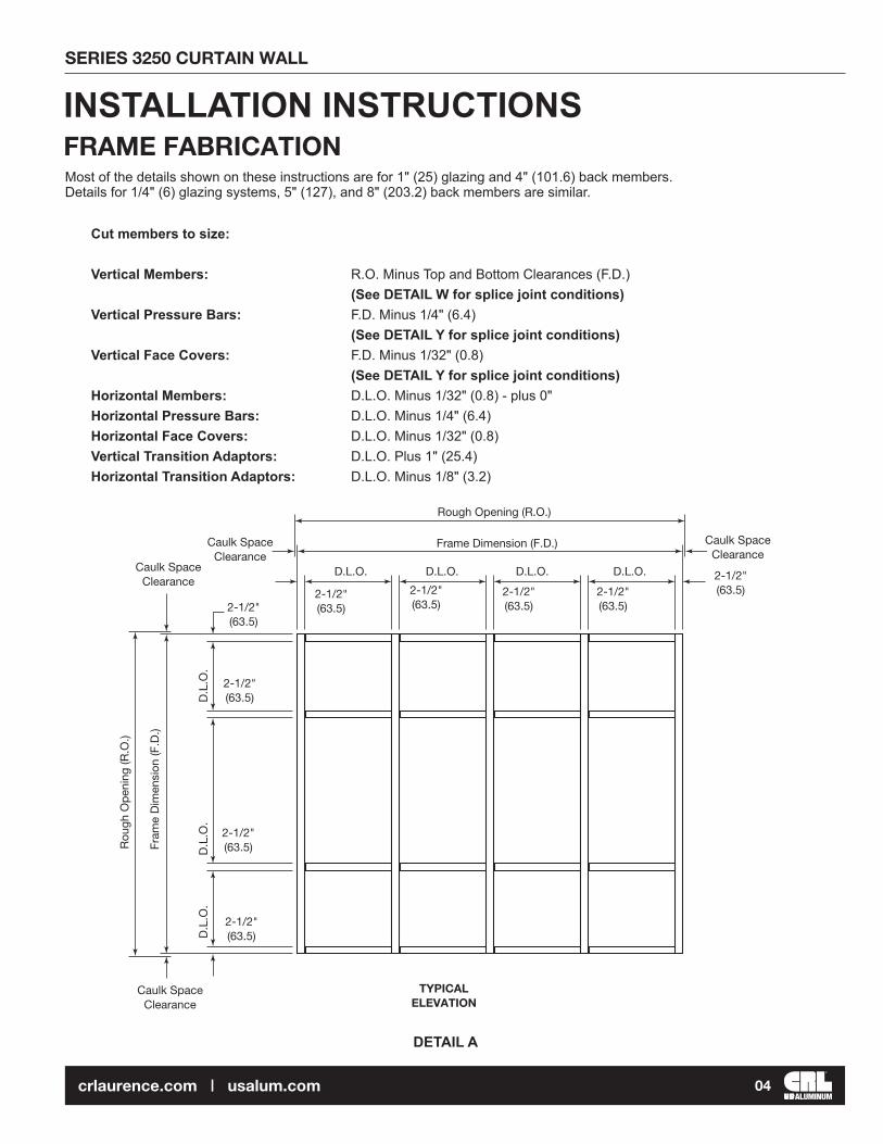
Cut members to size:
Vertical Members: R.O. Minus Top and Bottom Clearances (F.D.)(See DETAIL W for splice joint conditions)
Vertical Pressure Bars: F.D. Minus 1/4" (6.4)(See DETAIL Y for splice joint conditions)
Vertical Face Covers: F.D. Minus 1/32" (0.8)(See DETAIL Y for splice joint conditions)
Horizontal Members: D.L.O. Minus 1/32" (0.8) - plus 0"Horizontal Pressure Bars: D.L.O. Minus 1/4" (6.4)Horizontal Face Covers: D.L.O. Minus 1/32" (0.8)Vertical Transition Adaptors: D.L.O. Plus 1" (25.4)Horizontal Transition Adaptors: D.L.O. Minus 1/8" (3.2)
Most of the details shown on these instructions are for 1" (25) glazing and 4" (101.6) back members. Details for 1/4" (6) glazing systems, 5" (127), and 8" (203.2) back members are similar.
INSTALLATION INSTRUCTIONSFRAME FABRICATION
TYPICAL ELEVATION
Rough Opening (R.O.)
Rou
gh O
pen
ing
(R.O
.)
Fram
e D
imen
sion
(F.D
.)
Caulk Space Clearance
Caulk Space Clearance
2-1/2"(63.5)2-1/2"
(63.5)
2-1/2"(63.5)
2-1/2"(63.5)
D.L
.O.
D.L
.O.
D.L
.O.
D.L.O. D.L.O. D.L.O. D.L.O.
2-1/2"(63.5)
2-1/2"(63.5)
2-1/2"(63.5)
2-1/2"(63.5)
2-1/2"(63.5)
Caulk Space Clearance
Caulk Space Clearance
Frame Dimension (F.D.)

SERIES 3250 CURTAIN WALL
ALUMINUM05crlaurence.com | usalum.com
DETAIL B
DETAIL C
3. Fabricate ends of horizontal members for shear block pick-up screws (DETAIL C).
2. Mark on verticals the location of horizontal members and drill holes for shear blocks. Drill jigs are available (DETAIL B).Visit usalum.com for additional information.
at 4" (101.6) Member
Top of Horizontal
Vertical Member
DJ360 Drill Jig DJ991 (10" BM Drill Jig)
Drill (2) .177" (4.5) Dia. Holes. #17 Drill
1"(25.4)
2-1/8" (53.9)
3-1/8" (79.4) at 5" (127) Member5" (127) at 8" (203.2) Member
1-1/4"(31.8)
Hook Drill Jig on front of Vertical
Top ofHorizontal
DJ360 Drill Jig DJ991 (10" BM Drill Jig)
Drill (2) .177" (4.5) Dia. Holes. #17 Drill
1"
(25.4)3/4"
(19.1)
3/4"(19.1)
Drill (2) .177" (4.5) Dia. Holes. #17 Drill
DRILL JIG PREPARATION
NOTE: For larger projects we offer the Accufab Pro Tool Visit: usalum.com for additional information.

SERIES 3250 CURTAIN WALL
ALUMINUM06crlaurence.com | usalum.com
DETAIL E
4"(101.6)
1/8"(3.2)
1-1/2"(38.1)
1-1/2"(38.1)Typ.
1/4" (6.4)1-1/2"(38.1) 9/32" (7.1)
Dia. Holes (Typ)
9" O.C.(228.6)
1/8"(3.2)
Line of D.L.O. Line of D.L.O.
CW933Intermediate Horizontal Pressure Bar
Head Perimeter FillerCW957 for 1/4" (6) GlazingCW952 for 1" (25) Glazing
Sill Perimeter FillerCW957 for 1/4" (6) GlazingCW952 for 1" (25) Glazing
1-1/2"(38.1)
4"(101.6)
5. Vertical pressure bars feature 9/32" (7.1) Dia. attachment holes 9" (228.6) on center. Additional holes should bedrilled at 1-1/2" (38.1) from all ends and at vertical/horizontal intersections.
6. Fabricate two 1/4" x 1-1/2" (6.4 x 38.1) weep slots 4" (101.6) from each end in horizontal pressure bars and drill9/32" (7.1) dia. attachment holes 1-1/2" (38.1) from each end as shown on DETAIL E.
4. Fabricate bottom of horizontal face covers for weep holes 6" (152.4) from each end as shown in DETAIL D.
DETAIL D
6"(152.4)
6"(152.4)
3/16"(4.8)
1/4" (6.4) Dia. Weep Hole
CW901
SERIES 3250 CURTAIN WALL
ALUMINUM07crlaurence.com | usalum.com
DETAIL F
DETAIL G
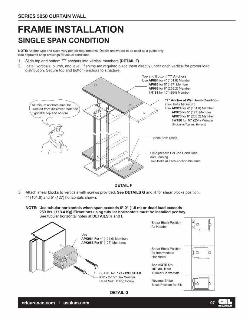
1. Slide top and bottom "T" anchors into vertical members (DETAIL F).2. Install verticals, plumb, and level. If shims are required place them directly under each vertical for proper load
distribution. Secure top and bottom anchors to structure.
3. Attach shear blocks to verticals with screws provided. See DETAILS G and H for shear blocks position.4" (101.6) and 5" (127) horizontals shown.
NOTE: Use tubular horizontals when span exceeds 6'-0" (1.8 m) or dead load exceeds250 lbs. (113.4 Kg) Elevations using tubular horizontals must be installed per bay. See tubular horizontal notes at DETAILS H and I.
NOTE: Anchor type and sizes vary per job requirements. Details shown are to be used as a guide only. See approved shop drawings for actual conditions.
FRAME INSTALLATIONSINGLE SPAN CONDITION
Top and Bottom "T" AnchorsUse AP964 for 4" (101.6) Member
AP965 for 5" (127) Member AP968 for 8" (203.2) Member 1N181 for 10" (254) Member
"T" Anchor at Wall Jamb Condition (Two Bolts Minimum)Use AP974 for 4" (101.6) Member
AP975 for 5" (127) Member AP978 for 8" (203.2) Member 1W180 for 10" (254) Member (Typical at Top and Bottom)
Aluminum anchors must be isolated from dissimilar materials. Typical at top and bottom.
UseAPK954 For 4" (101.6) MembersAPK955 For 5" (127) Members
(2) Cat. No. 12X212HHDTEK #12 x 2-1/2" Hex Washer Head Self Drilling Screw Reverse Shear
Block Position for Sill
Shear Block Position for Intermediate Horizontal
See NOTE On DETAIL H for Tubular Horizontals
Shear Block Position for Header
Field prepare Per Job Conditionsand Loading.Two Bolts at each Anchor Minimum
Shim Both Sides

SERIES 3250 CURTAIN WALL
ALUMINUM08crlaurence.com | usalum.com
8" (203.2 ) AND 10" (254 ) HOLLOW VERTICALS
DETAIL H
APK928 Shear Block for 8" (203.2) Tubular Horizontals Shown for AC956 Shear Block for 8" (203.2) AR901 Shear Block for 10" (254) Tubular Horizontals
Open Back Horizontals for 4" (101.6) and 5" (127) Horizontals (DETAIL H).
(2) #12 x 5/8" PHPSMS (Included)
(2) #8 x 3/4" Phillips Pan Head SMS Cat. No. 8X34PHPSMS
3/4" (19.1) at 8" Horizontals1" (25.4) at 4" (101.6) and 5" (127) Horizontals
6-3/8" (136.5) at 10" (254) Horizontals5-3/8" (136.5) at 8" (203.2) Horizontals 2-1/2" (63.5) at 4" (101.6) Horizontals 3-1/2" (88.9) at 5" (127) Horizontals
Dotted lines represent notched Open Back Horizontal.
NOTE: 8" (203.2) AND 10" (254)HORIZONTALSIt is necessary to also attach horizontal to shear block through top or bottom, as shown, to keep tight joint in rear. 4" (101.6) and 5" (127) TUBULAR HORIZONTALSAdditional pick up screws may also be required for special conditions. Pick up screw locations on top or bottom of horizontal will determine shear block position. (See location of holes for pick up screws on shear block)
1-1/8"(28.58)

SERIES 3250 CURTAIN WALL
ALUMINUM09crlaurence.com | usalum.com
DETAIL I
NOTE: Elevations using tubular horizontals at last bay (DETAIL I).
3-5/8" (92.1) Notch at 4" (101.6) Member 4-3/8" (117.5) Notch at 5" (127) Member 6-3/4" (171.5) Notch at 8" (203.2) Member 9-1/2" (241.3) Notch at 10" (254) Member)
HEAD
Notched Opening
HORIZONTAL INTERMEDIATE BELOW EYE LEVEL
Notched Opening
Notched Opening
SILL
Notched Opening
HORIZONTAL INTERMEDIATE ABOVE EYE LEVEL
Notch Tubular Intermediate Horizontal to Clear Shear Block
TUBULAR HORIZONTALS
1-1/2"(38.1)

SERIES 3250 CURTAIN WALL
ALUMINUM10crlaurence.com | usalum.com
DETAIL K
DETAIL J
4. Secure verticals to anchor clips after alignment has been completed.NOTE: Mullion spacing must be held to within ±1/32" (0.8). Check overall frame dimension every
four bays to monitor dimension build up.
DETAILS J and K show fixed (dead load) and expansion (windload) anchors. Anchor type and size vary per job requirements. Details shown are to be used as a guide only. See approved shop drawings for actual conditions.
MULTI-SPAN CONDITION
Drill Holes after Alignmenthas been completed.
AP360Nylatron Slip-Pad
Primary Bolts with NutsFlat Washer and Lock Washer
Fixed Anchor(Deadload Anchor)
Drill Holes after alignmenthas been completed.
1-1/2" min.(38.1)
1-1/2" min.(38.1)
AP360Nylatron Slip-Pad
Primary Bolts with Nuts,Flat washer, and Lock WasherBack Off Nut 1/4" Turn AfterTightening to Allow forThermal Movement.
Expansion Anchor(Windload Anchor)
SERIES 3250 CURTAIN WALL
ALUMINUM11crlaurence.com | usalum.com
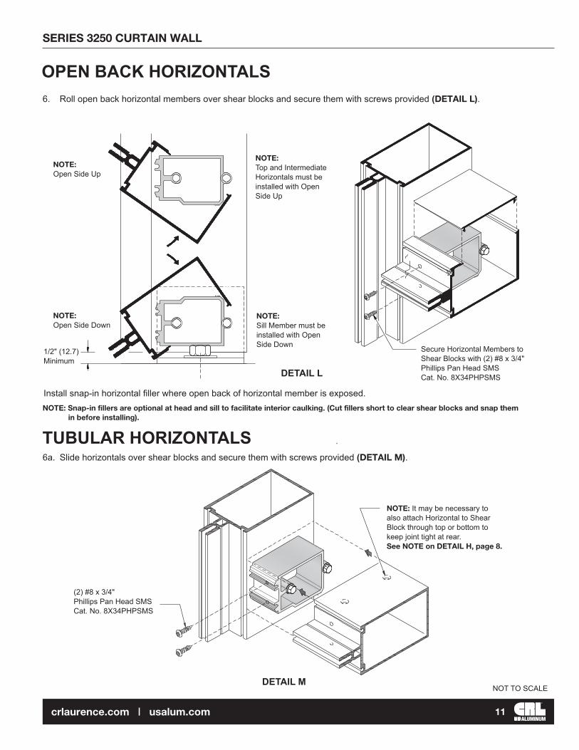
DETAIL L
6. Roll open back horizontal members over shear blocks and secure them with screws provided (DETAIL L).
6a. Slide horizontals over shear blocks and secure them with screws provided (DETAIL M).
NOTE: Snap-in fillers are optional at head and sill to facilitate interior caulking. (Cut fillers short to clear shear blocks and snap them in before installing).
NOTE:Sill Member must be installed with Open Side Down
NOTE:Top and Intermediate Horizontals must be installed with Open Side Up
Install snap-in horizontal filler where open back of horizontal member is exposed.
OPEN BACK HORIZONTALS
TUBULAR HORIZONTALS
(2) #8 x 3/4" Phillips Pan Head SMS Cat. No. 8X34PHPSMS
NOTE: It may be necessary to also attach Horizontal to Shear Block through top or bottom to keep joint tight at rear. See NOTE on DETAIL H, page 8.
DETAIL MNOT TO SCALE
NOTE:Open Side Down
NOTE:Open Side Up
1/2" (12.7) Minimum
Secure Horizontal Members to Shear Blocks with (2) #8 x 3/4" Phillips Pan Head SMS Cat. No. 8X34PHPSMS

SERIES 3250 CURTAIN WALL
ALUMINUM12crlaurence.com | usalum.com
DETAIL O
DETAIL N
8. Seal joint between horizontal and vertical. Also seal over head of screws in the glazing pockets.9. Apply sealant at the three contact areas of end dams. Also fill the vertical gasket reglet with
sealant at the End Dam location (DETAIL O).10. Slide End Dams into place. NOTE: End Dams occur at head and sill also.
7. Once all verticals and perimeter members are installed, seal around perimeter. Perimeter caulking must be completedprior to installation of glass and pressure bars. Ensure perimeter sealant has smooth transition across verticalEnd Dams (DETAIL N).
Cat. No. CRL 95C/M64/M66Perimeter Caulking
1" (25) GLAZING SYSTEM
1/4" (6) GLAZING SYSTEM
Apply CRL Cat. No. RTV408 Sealant to Vertical Mullions before attaching Closure Plate
Closure Plate Cat. No. CP900/CP925
CRITICAL SEALApply Cat. No. CRL RTV408 Sealant to Horizontal/Vertical Joint Intersection
CRITICAL SEALFill the Vertical gasket reglet with Cat. No. CRL RTV408 Sealant right behind the End Dam.
CRITICAL SEALApply Cat. No. CRL RTV408 Sealant to the Three Contact Areas.
HD975 for 1" (25) Glazing HD973 for 1/4" (6) Glazing
CRITICAL SEALApply Cat. No. CRL RTV408 Sealant over Heads of Screws.
NOTE: Consult Sealant Manufacturer for Proper Cleaning and Priming Recommendations
SIDE VIEW SIDE VIEW
Apply CRL Cat. No. RTV408 Sealant to Vertical Mullions before attaching Closure Plate
Closure Plate Cat. No. CP900/CP925 (Not to Scale)
Vertical Mullion Vertical MullionNOTE: Consult Sealant Manufacturer for Proper Cleaning and Priming Recommendations

SERIES 3250 CURTAIN WALL
ALUMINUM13crlaurence.com | usalum.com
DETAIL P
1. Cut gaskets allowing 1/8" (3.2) extra length per foot of aluminum extrusion to allow for shrinkage.Vertical gaskets on mullion run past horizontal gaskets by 5/8" (16) (DETAIL R.Horizontal gaskets butt against vertical gaskets.
2. Install back gaskets into vertical and horizontal members and front gaskets into pressure bars. Horizontal pressure bargaskets should extend 1/8" (3.2) beyond each end of the extrusions. Vertical pressure bar gaskets run continuous.
3. Position two setting blocks for each glass lite as directed by the dead load charts and shop drawings.4. Peel off side blocks paper backing and locate them, two per glass lite, at approximately mid-height of glass (DETAIL P).
5. Apply bead of sealant at interior gaskets corners 2" (50.8) in each direction (DETAIL R).6. Install glass and center in opening. Use CW368 Temporary Glass Retainers to hold glass in place until pressure
bars are installed (DETAIL Q).
NOTE: This formula does not take into account glass tolerances. Consult glass manufacturer before ordering glass.
Remove gaskets from carton and lay flat in a clean, dry area in order to recover shape. Allow gaskets to relax at least two hours at temperatures above 50°F (10°C). Glaze with gaskets above 40°F (4°C). If necessary warm gaskets in a hot box before installing.
Use NP430 dense gasket at exterior and NP420 sponge gasket at interior.
GLASS WIDTH and HEIGHT = DAYLIGHT OPENING + 1" (25.4)
GLAZINGGLASS SIZES
Two Side Blocks per Glass LiteNOTE: Due to Glass Tolerances Side Block may be Installed after Glass
Peel off Back-UpPaper and stickBlock to Verticalat Glass Mid-Point
Setting BlocksTwo Per Glass Lite
Schematic ViewEdge Block(Anti-Walk Block)AW900 for 1/4" (6) Glazing AW901 for 1" (25) Glazing
Of GlassCL

SERIES 3250 CURTAIN WALL
ALUMINUM14crlaurence.com | usalum.com
DETAIL Q
DETAIL R
Install vertical pressure bar bolts from bottom to top and horizontal pressure bar bolts from center outward. Always locate bolts 1-1/2" (38.1) maximum from vertical/horizontal intersections to ensure proper pressure over End Dams (DETAIL S). Be sure pressure bar spacer is not disengaged.
8. Install vertical pressure bars first leaving 1/8" (3.2) gaps at top and bottom. Using a torque wrench, torquebolts to 30 inch pound (3.4 Nm). Increase torque to 50 to 60 inch pound (5.7 to 6.8 Nm) minimum after all foursides have been secured.
7. Apply Cat. No. CRL RTV408 Sealant to face of End Dams. This is a Critical Seal Area (DETAIL R).
CW368 Temporary Glass Retainer. Torque to 30 in. Pound (3.4 Nm)
NOTE: Do Not Over-Torque Glass Retainer Bolts.Use One Retainer Per Each 150 lbs. (667.2 N) of load.(i.e. if Glass Height x Glass Width x Windload = 350 lbs. Use Three Retainers)
PRESSURE BAR INSTALLATION
CRITICAL SEAL AREA Apply Cat. No. CRL RTV408 Sealant to the face of End Dams right before installing Pressure Bars.
NOTE:Vertical Gaskets Do Not Run Through to Allow for End Dam installation.They extend approximately 5/8" (16) Past the Edge of the Horizontal.
Apply Cat. No. CRL RTV408 Sealant to Interior Gaskets Corner 2" (50.8) in each direction.
Shown After GlazingShown Before Glazing CL
2"(50.8)2"
(50.8)
5/8" (16)
NOTE: Consult Sealant Manufacturer for Proper Cleaning and Priming Recommendations

SERIES 3250 CURTAIN WALL
ALUMINUM15crlaurence.com | usalum.com
9. Center horizontal pressure bars in opening leaving 1/8" (3.2) gaps at each end.NOTE: Weep slots must be in top side of all horizontal pressure bars and level with bottom of glazing pocket toensure proper drainage (DETAIL S).
10. Seal gaps at vertical/horizontal intersections and at top and bottom of vertical pressure bars (DETAIL S).
11. Install Vertical Face Covers first. Do not disturb top and bottom closure plates when installing face covers.Pinning of vertical face cover is required to prevent slippage. Use one pin on each side per cut length, concealedbehind horizontal face cover closer to center line or as shown on shop drawings (DETAIL T).
12. Install snap-in Horizontal Face Covers with the weep holes located on the bottom side. NOTE: Extended face coversrequire a special pressure bar. Pin vertical extended covers with one 1/8" (3.2) dia. pop rivet on each side perengineered calculations (optional #10 x 1/2" FHSMS) (DETAIL U).Extended Horizontal Covers must be pinned on top side at both ends.
Care must be taken to prevent damage of Face Covers during installation. Use a piece of wood such as 2" x 4" x 12" (51 x 102 x 305) and a 3" (76.2) diameter Stanley Three Pound Compo-Cast Dead Blow Soft Face Hammer.
FACE COVER INSTALLATION
1/8" (3.2) Pop Rivet at Center of Cut Length at Each Side (Concealed behind Horizontal Face Cover)
1/16" x 1/2" (1.6 x 12.7) Roll Pin at Center of Cut Length on Each Side. (Concealed behind Horizontal Face Cover) CW933 SX215
DETAIL S
Weep Slots (Two Per Bay)Always in Upper Side
Seal All Gaps and Tool Sealant making sure it Will Not Interfere with the Snap on Face Covers. (Typ.)
NOTE: Weep Slots are Required in All Horizontal Pressure Bars including the Head or Top Horizontal
Pressure Bar, Typical
1/8" (3.2) Gap
1/8" (3.2) Gap
1-1/2" (38.1)
1-1/2" (38.1)
4" (101.6)
3" (76.2)
9" (228.6) O.C. (Typ.)
1-1/2" (38.1)
DETAIL T
DETAIL U

SERIES 3250 CURTAIN WALL
ALUMINUM16crlaurence.com | usalum.com
1. Apply Cat. No. CRL RTV408 sealant into gasket reglets before installing snap-in transition adaptors.2. Install vertical adaptors first.3. Install horizontal adaptors and seal horizontal/vertical joints. Tool sealant (DETAIL V).
TRANSITION GLAZING
Vertical Adaptor runs throughNote: Discontinue Vertical Adaptors at Splice Joints
Horizontal Adaptors
DETAIL V
D.L.O. - 1/8" (3.2)
D.L.O.
D.L
.O.
D.L
.O. +
1" (
25.4
)
Using Cat. No. CRL RTV408Seal Horizontal/Vertical Joint and Tool Sealant.
Fill Gasket Reglet with Sealant before Installing Adaptors (This is a Continuous Seal)
NOTE: Consult Sealant Manufacturer for Proper Cleaning and Priming Recommendations

SERIES 3250 CURTAIN WALL
ALUMINUM17crlaurence.com | usalum.com
DETAIL W
1. Clean splice sleeves and all joint surfaces. Apply CRL Cat. No. 827T2 Bond Breaker Tape at areas where sleeve will besealed to avoid three side adhesion (DETAIL W).
2. Slide sleeve into the upper member before it is installed and tape to hold it in retracted position (DETAIL W).
NOTE: Splice joints are designed to accommodate thermal movement only. They do not compensate for variations in floor levels.
A 1/2" (12.7) minimum joint is recommended. Use a 1/2" (12.7) spacer shim to set and hold the mullion joint constant during erection. Remove the shim after attaching the verticals to the anchors. Splice joints must occur at spandrel areas.
Splice joint width should be based on sealant movement capability and on the following formula:
Linear expansion for aluminum, in inches = Length (") x F° difference in temperature x .0000129Linear expansion for aluminum, in millimeters = Length (mm) x C° difference in temperature x .02322
VERTICAL SPLICE JOINTS
Apply Cat. No. CRL 827T2 Bond Breaker Tape to Sleeve at Joint Area
Splice SleeveUse SL944 for 4" (101.6) Member
SL945 for 5" (127) Member SL948 for 8" (203.2) Member SL901 for 10" (254) Member
Splice Sleeve
2-3/4"(69.8)
Stop Screw Cat. No. ST251 #10 x 1" HWS
See DETAIL Y
1/2"(12.7)
3. Install stop screw #10 x 1" HWS Cat. No. ST251, 2-3/4" (69.8) down from top of extrusionat inside of lower member (DETAIL X).
4. Install upper member and let extruded sleeve slide down until it sits on top of stop screw.5. Seal joint over sleeve as shown on DETAIL Y. When transition adaptors for 1/4" (6) spandrel
are used they should be discontinued at splice joint and installed after splice joint is sealed.Stagger joints on back members, pressure bars, and face caps as shown on DETAIL X.
6. Seal pressure bar joint (DETAIL Y).7. Install face covers and seal joint using backer rod as required (DETAIL X).

SERIES 3250 CURTAIN WALL
ALUMINUM18crlaurence.com | usalum.com
DETAIL X
DETAIL Y
1/2" (12.7) Seal and Tool Joint Using Cat. No. CRL 95C
Apply Cat. No. CRL 827T2Bond Breaker Tape
Aluminum Face Cap Remover ToolCat. No. FCR1
1-1/2" (38.1)
1-1/2" (38.1)
SPLICE SLEEVE
Seal Face Cover Joint and Tool (Use Backer Rods as Required)
Apply Cat. No. CRL 827T2 Bond Breaker Tape
Splice Sleeve
1" (25.4)
4" (101.6)
2-3/4"(69.8)
Use Backer Rod to Facilitate Face Cover Seal
1/2" (12.7) Pressure Bar Splice
1/2" (12.7) Min. Splice Joint Width
1/2" (12.7)Face Cover Splice Joint
1/2" (12.7) Seal Pressure Bar Joint Using Cat. No. CRL 95C
NOTE: Consult Sealant Manufacturer for Proper Cleaning and Priming Recommendations
Stop Screw Cat. No. ST251 #10 x 1" HWS

SERIES 3250 CURTAIN WALL
ALUMINUM19crlaurence.com | usalum.com
Entrance Frames may be installed simultaneously with Curtain Wall or after Curtain Wall installation has been completed. Use CW917 or CW916 Pocket Fillers to close glazing pocket at door side.
ENTRANCE FRAMES
CW917Pocket Filler (CW916 for 1/4" Glazing)
Apply Cat. No. CRL 95C/M64/M66
Shim at Fastener Locations
Seal Joint using Cat. No. CRL RTV408
Attach Door Jamb to Vertical with #10 x 3/4" PHSMS 24" (609.6) O.C.
TJ450 Door Jamb
Seal Pocket of Door Subframe up to Top of Threshold
DS047Snap-In Door Stop for Offset Hung Door
Attach Door Jamb to Vertical with #10 x 3/4" PHSMS 24" (609.6) O.C.
TJ450 Door Jamb
Apply Cat. No. CRL RTV408 to Joint Seal between Door Jamb
P050Snap-In Pocket Filler for Center Hung Door
DETAIL AACenter Hung Door
TH250 Threshold for Offset Hung Door
Trim Closure Plate at Door Jamb Side to Clear Door Frame
Apply Cat. No. Cat. No. CRL 95C/M64/M66 Continuous Exterior Perimeter Seal
CW917Pocket Filler (CW916 for 1/4" Glazing)
TH400 Threshold for Center Hung Door
Apply Cat. No. CRL RTV408 Sealant between Door Frame and Curtain Wall. Vertical must marry with Exterior Perimeter Seal
Trim Closure Plate at Door Jamb Side to Clear Door Frame
NOTE: Consult Sealant Manufacturer for Proper Cleaning and Priming Recommendations
DETAIL Z

SERIES 3250 CURTAIN WALL
ALUMINUM20crlaurence.com | usalum.com
DETAIL BB
1. Cut Door Adaptor Members to length.
2. Drill 5/16" diameter anchor holes in all cut to length Adaptors 1-1/2" (38.1) from each end and 9" (228.6)on center. See DETAIL BB.
NOTE: Isolator must be in place prior to drilling anchor holes.
NOTE: Flush Door Adaptors Are Not Available for Series 3150 Butt Glaze Applications
CW958Header Adaptor Length = DOOR OPENING WIDTH minus 1/32" (.8)Jamb Adaptor Length = DOOR OPENING HEIGHT plus 9/16" (14)
CW906Header Cap Length = DOOR OPENING WIDTH minus 1/32" (.8)Jamb Cap Length = DOOR OPENING HEIGHT plus 9/16" (14)(Field cutting may be required to obtain a tight joint with vertical cap above)
CW219Header Door Stop Length = DOOR OPENING WIDTH minus 1/32" (.8)Jamb Door Stop Length = DOOR OPENING HEIGHT minus 1-3/32" (27.8)
FABRICATION
FLUSH DOOR ADAPTOR
CW958
Isolator
Holes Centered on Groove
1-1/2"(38.1)
1-1/2"(38.1)
9" O.C. (Typ.)(228.6)
5/16" Dia. Holes(7.9)

SERIES 3250 CURTAIN WALL
ALUMINUM21crlaurence.com | usalum.com
DETAIL B
3. Fabricate Header Adaptor for weep slots and additional anchor holes as shown in DETAIL B.(Refer to usalum.com for entrances and frames for flush bolt and panic rod strike fabrication.)
4. For offset pivot doors, fabricate Header Adaptor for pivot (left hand shown), weep slots and additional anchor holes asshown in DETAIL C. Notch Face Cap for pivot clearance as shown in DETAIL D. (Refer to usalum.com for entrances and frames section of this manual for flush bolt and panic rod strike fabrication.)
FABRICATIONFLUSH DOOR ADAPTOR FABRICATION AND INSTALLATION
4"(101.6)
4"(101.6)
1-1/2"(38.1)
3/16"(4.8)
1-1/2"(38.1)
CW958
1-1/2"(38.1)
1-1/2"(38.1)
9" O.C.(228.6)
11/64" (4.4) Dia. Holeor #16 Drill Bit
WEEP SLOTS ANCHOR HOLE
DOOR OPENING WIDTH Minus 1/32"
DETAIL C
DETAIL D
C L
C L
CW958
4"(101.6)
4"(101.6)
27/32"(21.4)
1-5/32"(29.4)
15/32"(11.9)
15/32"(11.9)
1-1/2"(38.1)
1-1/2"(38.1)
1/4"(6.4)
1-3/16"(30.2)
1/16"(1.6)
CW206
11/64" (4.4) Dia. Holeor #16 Drill Bit 9" O.C.
(228.6)
1-1/2"(38.1)
3/16"(4.8)
1-1/2"(38.1)
DOOR OPENING WIDTH minus 1/32"
Drill and Countersink for 1/-20 FHMS
WEEP SLOTS ANCHOR HOLE

SERIES 3250 CURTAIN WALL
ALUMINUM22crlaurence.com | usalum.com
5. Fabricate for Lock Jamb see DETAIL FF.(right hand shown, left hand opposite)
FABRICATION
FLUSH DOOR ADAPTOR
15/64"(5.9)
1-9/32"(32.5)
9" O.C.(228.6)
1-1/2"(38.1)
DO
OR
OP
EN
ING
HE
IGH
T p
lus
9/16
"
11/16"(17.5)
.125" R.(3.2)
1-5/16"(61.4)
1/2"(12.7)
13/16"(20.6)
3/8"(9.5)
1-1/2"(38.1)
1"(25.4)
7/16"(11.1)
1-1/16"(27)
1-1/4"(31.8)
1/8"(3.2)
21/64"(8.3)
25/32"(19.8)
30-1/2"(774.7)
DETAIL FF
Cut out for DH129 Hook Bolt Lock.
11/64" (4.4) Dia. Hole or #16 Drill Bit
6. Fabricate for Butt Hinges see DETAIL GG.(left hand shown, right hand opposite)
EQ
UA
LE
QU
AL
5/32" R.(3.9)
1/8"(3.2)
3/8"(9.5)
1"(25.4)
1-1/2"(38.1)
1-1/16"(27)
DETAIL GG
11/64" (4.4) Dia. Hole or #16 Drill Bit Locate 9" (228.6) O.C.
Drill and countersinkfor #12 FHMS7/16" (11.1) Dia. Countersink
1-1/4"(31.8)
9" O.C.(228.6)
4-17/32"(115.1)
DO
OR
OP
EN
ING
HE
IGH
T P
lus
9/16
"
7/16"(11.1)
1-7/16"(36.5)
9" O.C.(228.6)
15/64"(5.9)
1-9/32"(32.5)
1-1/2"(38.1)
2-17/64"(57.5)
134"(3.4)
25/32"(19.8)
1-1/16"(27.0)7/16"(11.1)
21/64"(8.3)
7/16"(11.1)
1-1/4"(31.8)
9-11/16"(246.1)
2-17/64"(57.5)
6-11/16"(169.9)

SERIES 3250 CURTAIN WALL
ALUMINUM23crlaurence.com | usalum.com
DETAIL HH
7. Fabricate for Offset Pivots see DETAIL HH. (left hand shown; right hand opposite)
FABRICATIONFLUSH DOOR ADAPTOR
Bottom of Door Opening(Reference)
C L
Top of Cut-Out
9/16"(14.3)
15/64"(5.9)
1-3/8"(34.9)
25/32"(19.8)
Doo
r O
pen
ing
÷ 2
3/8"(9.5)
1-1/2"(38.1)
15/64"(5.9)
21/64"(8.3)
25/32"(19.8)
3/8"(9.5)
11/32"(8.7)
1/8"(3.2)
1-1/4"(31.8)
7/16"(11.1)
1"(25.4)
1-1/2"(38.1)
1-1/16"(27.0)
1-9/16"(39.7)
1"(25.4)
3/8"(9.5)
1/2"(12.7)
Front View Side View
Top of Door Opening (Reference)
Drill and Countersinkfor 1/4"-20 FHMS
11/64" (4.4) Dia. Hole or #16 Drill Bit
D.O
.+ 9
/16"
(14.
3)
9" O.C.(228.6)
Drill and Countersinkfor #12 FHMS7/16" (11.1) Dia. Ctrsnk

SERIES 3250 CURTAIN WALL
ALUMINUM24crlaurence.com | usalum.com
DETAIL II DETAIL KKDETAIL JJ
DETAIL LL
8. For butt hung application, install Hinge Back Up Plates and Threshold Clips as shown in DETAIL II and DETAIL JJ.For offset pivot application, install bottom frame portion pivot(s) as shown in DETAIL KK. Single doors requirethreshold clip at lock jamb (DETAIL JJ).
9. Install Gaskets in Door Adaptors.
1. Seal face of End Dams as shown in DETAIL R.2. Install Jamb Door Adaptors using MS222 Pressure Bar Bolts as shown in DETAIL LL. Refer to page 14 of the glazing
portion of this section for bolt tightening procedures. Vertical adaptors extend from floor to 9/16" (14.3) abovebottom of door header/horizontal. Install Head Door Adaptor using MS222 Pressure Bar Bolts as shown in DETAIL LL.
3. Secure adaptors to mullion and head side walls with #8 tek screws as shown in DETAIL LL.
NOTE: Prior to adaptor installation all End Dams must be installed and sealed. Transom and sidelite glass must be in place.
FABRICATION
INSTALLATION
FLUSH DOOR ADAPTOR
These hardware items must be applied prior to door adapt or installation.
TC50000Anchor Clip(Supplied with Door Hardware) 0P400
Frame Portion Bottom Pivot(Supplied with Door Hardware)
MS172 (4)#12-24 x 1/2"
(2) MS172#12-24 x 1/2" (2) MS172
#12-24 x 1/2"
BP45900Backup Plate
#8 x 1/2" PH Tek Screw
Seal Gasket Pocket at Flush Door Adaptor
MS222Pressure Bar Screw

SERIES 3250 CURTAIN WALL
ALUMINUM25crlaurence.com | usalum.com
DETAIL MM
DETAIL NN DETAIL OO
4. Seal all Pressure Bar Bolt Heads with Cat. No. CRL RTV408 (See DETAIL MM).5. Seal gaps at intersections of Pressure Bars and Door Adaptors with CRL RTV408.
NOTE: This is a critical seal.
6. Install thresholds into opening using screws provided with door hardware. See DETAIL NN for butt hung,DETAIL OO for offset pivot application.
INSTALLATION
FLUSH DOOR ADAPTOR
Seal Pressure Bar Bolt Heads
Seal Intersecting Pressure Bar and Adaptor Joints
Threshold Clip
Seal Anchor Screws
Seal Pivot Screws
Attach Threshold To Clips with (2) MS176#12-24 3/8" FH Screws
0P400 Frame Portion Bottom Pivot
(2) MS176 #12-24 x 3/8" FH Screws
NOTE: Consult Sealant Manufacturer for Proper Cleaning and Priming Recommendations

SERIES 3250 CURTAIN WALL
ALUMINUM26crlaurence.com | usalum.com
DETAIL PP
DETAIL QQ
7. Snap on Face Caps (DETAIL PP). Vertical face caps run from floor to 9/16" (14.3) above bottom of Header.(Field cutting to length is recommended)
8. Snap Door Stop on Header Adaptor (DETAIL PP). (Head door stop runs through)9. Snap Door Stops on Jamb Members (DETAIL PP).
10. For offset pivot doors, install frame portion pivots as shown (DETAIL QQ).
INSTALLATIONFLUSH DOOR ADAPTOR
Face Cap
Snap in PlaceDoor Stop
(3) MS172 #12-24 x 1/2"
D062(Frame Header Portion)
(2) MS19400 1/4-20 x 1/2"
DH022 (Frame Portion)

SERIES 3250 CURTAIN WALL
ALUMINUM27crlaurence.com | usalum.com
CRL12:1 Ratio Strap Frame Caulking Gun
CAT. NO. GA1203
CRL Complete Set of Seven All Stainless Steel Spatulas
CAT. NO. AB958G
CRL Backer Rod Roller Tool
CAT. NO. SBRR
CRL Plastic Bearing Shimstrips
CAT. NO. PBS06
JOB SITE ESSENTIALSHelpful Tools and Supplies for Installing CRL U.S. Aluminum Entrances, Storefronts, Windows, and Curtain Wall SystemsALUMINUM
CRL Aluminum Face Cap Remover Tool
CAT. NO. FCR1
CRL GlovesCAT. NO. KF1TL
CRL Utility KnifeCAT. NO. K82
CRL Utility Knife BladesCAT. NO. 1992C
CRL Soft-Face Power HitterCAT. NO. ST57532
CRL 95C Silicone Building Sealant
CRL RTV408 Neutral Cure Silicone
CRL33S Silicone Sealant
CRL M64 Modified Smooth Polyurethane Construction Sealant
CRL M66 Modified Grainy Polyurethane Construction Sealant
CAT. NO. M66
CRL Plastic Horseshoe ShimsCAT. NO. PHS18
CRL Saint-Gobain/Norton V2100 Thermalbond® Structural
Glazing Spacer Tape CAT. NO. V2100