seminar alternative hydroelectricity - university of...
TRANSCRIPT
University of LjubljanaFaculty of Mathematics and Physics
Seminar
Alternative hydroelectricity
Simon Copar
Mentor: prof. Rudolf Podgornik
April 27, 2009
Abstract
In this seminar I will explain two novel ideas from the field of alternative power sources. TheAnaconda, device for extracting energy from waves using only a rubber tube and a turbine, andVivace from Pax research institute, which uses vorticity induced vibration to convert slow steadyflows into periodic movement. The highlight of both projects is use of resonant mechanism toget best efficiency. I shall describe basic science of their operation and the advantages againstother power sources. Both technologies are still in research phase.
1 Introduction
From the discovery of the battery in the beginning of 19th century, people have been mainly harvestingenergy stored in chemical bonds. This includes fossile fuels, biofuels and galvanic cells. All thesepower sources, along with nuclear power, are not renewable. This means that natural reserves arewaning, which has become more and more pressing problem in last few decades. On the otherhand, earth receives on average 1.4 kW/m2 of power [1] and most of this energy is used for drivingweather phenomena. Incoming energy is stored in the form of atmospheric and water flows andthermal gradients. So-called alternative energy sources still have negligible share in worldwide powerproduction. Main reasons for this are high cost, low power density and variable output. In search ofmore reliable and cheap energy, man has found many ways of harnessing power, stored in water andatmosphere. In next paragraphs I will present Anaconda and Vivace, which are not yet in commercialuse.
2 Anaconda
Anaconda is a technology which uses flexible rubber tubes to extract energy from waves on watersurface. Older variations of this concept are already in use. They use rigid rafts, chained together[2]. The rafts are mainly build from concrete and the power is produced from buckling at the joints,which include hydraulic or pneumatic pistons. Its efficiency is less than optimal and with moremoving parts, this system is more prone to wear and external damage. The first full scale powerproduction unit of this type failed in March 2009 after just few weeks of operation at 2.25 MW [3].This is just onother reason to develop something that doesn’t contain joints and rigid structure.Main part of Anaconda is a long rubber tube, which is completely submerged in water. It’s eitherfloating directly below the surface or else mounted to the seabed. The pressure difference, producedby waves, excites bulges that propagate along the tube with well defined speed. Resulting pressureat the end of the tube is then used to power some kind of turbine. The power producing part and thetube are mainly independent and can be described and built separately. Unlike the buckling devices(e.g. Pelamis, which is already in use [4]), resonance behaviour has central role in its operation. Inthe next section I will describe basic hydrodynamics needed for description of this device.
2.1 Linear waves theory
We are interested only in gravity driven waves, so the wavelengths involved will be on the scale offew meters. The result is easily obtained for small amplitudes and ignorable nonlinear effects. Thisprovides a starting point for experimental verification and refinement of the product.In linear approximation we can describe water waves with the height profile
η = a cos(kx− ωt) (1)
Incompressibility and is ensured by using velocity potential Φ. Velocity is then defined as gradientof this potential, in particluar u = ∂Φ
∂x and v = ∂Φ∂y . Incompressibility condition transcribes to the
need for Φ to satisfy Laplace equation. Together with boundary condition, which is explained indetail in [5, 6], we find the ansatz
Φ =ω
kaeky sin(kx− ωt) (2)
Amplitude of movements and pressure are dampened exponentially with depth. For simplicity, weassumed infinite depth, but the result for finite depth is not much different. Euler equation formotion of fluids for this case is p = −ρ∂Φ
∂t which gives us pressure distribution.
p = ρω2
kaeky cos(kx− ωt) (3)
1
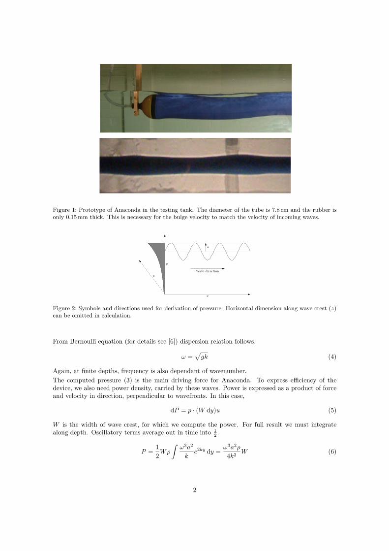
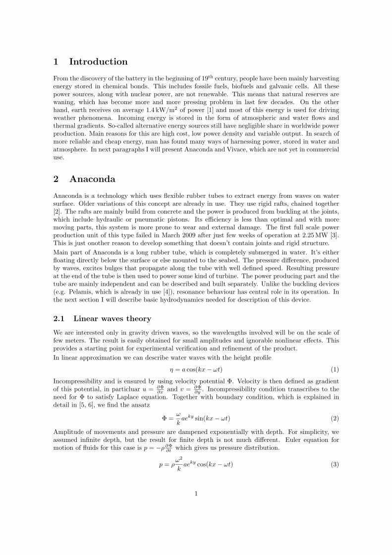
Figure 1: Prototype of Anaconda in the testing tank. The diameter of the tube is 7.8 cm and the rubber isonly 0.15mm thick. This is necessary for the bulge velocity to match the velocity of incoming waves.
x
y
z
a
Wave direction
Figure 2: Symbols and directions used for derivation of pressure. Horizontal dimension along wave crest (z)can be omitted in calculation.
From Bernoulli equation (for details see [6]) dispersion relation follows.
ω =√
gk (4)
Again, at finite depths, frequency is also dependant of wavenumber.The computed pressure (3) is the main driving force for Anaconda. To express efficiency of thedevice, we also need power density, carried by these waves. Power is expressed as a product of forceand velocity in direction, perpendicular to wavefronts. In this case,
dP = p · (W dy)u (5)
W is the width of wave crest, for which we compute the power. For full result we must integratealong depth. Oscillatory terms average out in time into 1
2 .
P =12Wρ
∫ω3a2
ke2ky dy =
ω3a2ρ
4k2W (6)
2
Using dispersion relation and surface pressure amplitude |pw| = ρga, the result is
Pw
W=|pw|2
4ωρ(7)
The power is evidently proportional to the square of pressure amplitude.
2.2 Tube elasticity
The rubber tube is assumed to be completely filled with water. We must relate the interior pressurewith tube diameter. We make use of Hooke law to get tangent force Ft. Let the tube diameter be r,relaxed diameter R, its thickness h and Young modulus E. For narrow cyllindrical strip we computeinternal tension
dFt
h dx= E
r −R
R(8)
To calculate pressure we need normal force, which equals dFn
r dφ = Ft
r for circular tube (see figure 3).This force tries to compress the tube and causes raised pressure inside.
pb =d2Fn
r dφdx=
dFt
r dx(9)
pb is our bulge pressure: the pressure, caused solely by the stretched tube. Putting these resultstogether we obtain
pb =hE(r −R)
Rr(10)
Differentiating this equation and using tube crossection S = πr2, dS = 2πr dr we get
dS
S= D dpb (11)
This equation defines distensibility D = 2REh [4].
Figure 3: Geometry of the tube slice for which we are computing the pressure. The tangent forces causenormal pressure due to the curved shape of the rubber strip.
2.3 Wave equation
The water inside the tube follows the equation of motion and continuity quation. The water isassumed inviscid and incompressible, as above.
∂u
∂t= −1
ρ
∂p
∂x(12)
3
∂S
∂t= −S
∂u
∂x(13)
Combining these, we get∂2S
∂t2=
S
ρ
∂2p
∂x2(14)
Differentiating equation with respect to time we get
∂2S
∂t2= DS
∂2pb
∂t2(15)
We eliminate the crossection by merging above results. As the rubber only produces pressure differ-ence, the total internal pressure is p = pb + pw.
∂2pb
∂t2=
1Dρ
∂2(pb + pw)∂x2
(16)
pw being pressure generated by waves. This is driven wave equation for bulge pressure, with speedc0 = 1/
√Dρ.
For linear waves, we can assume harmonic pressure from (3), pw = |pw| cos(kx−ωt). The ansatz forpb must have the same form. Equation (16) directly gives amplification factor
F =|pb||pw|
=1
c2/c20 − 1
=1
k20/k2 − 1
(17)
c = ω/k is external wave velocity. This gives evidently resonant behaviour for the waves around thetube’s natural mode. This factor holds for infinite tube. However, for full solution of finite problemwe must satisfy boundary conditions. In our case we assume that the pressure at the beginning ofthe tube is constant. This is satisfied by adding the right amount of natural solution with tube’sproper velocity.
pb = |pb|(cos(ωt− kx)− cos(ωt− k0x)) c0 =ω
k0(18)
It’s better to combine the cosine terms to separate time oscillations from modulation.
pb = −|pb| cos(ωt− kx) sin(x∆k/2) (19)
We used average wawenumer k = 12 (k + k0) and the distance from resonance ∆k = k0 − k. This
modifies the amplification factor
F =k2
k∆ksin(x∆k/2) (20)
which simplifies to F = kx for wavenumbers close to the resonance. This means that pressureamplitude is directly proportional to length of the tube and the power grows quadratically. Atresonance, the phase difference between bulge pressure and wave pressure is exactly π/2. In this casethe bulge is pushed from behind by the wave and is receiving maximum amount of work along thewhole length.
2.4 Capture width
Convenient way for expressing efficiency is to tell effective width of wave crest, on which the incomingenergy flux is completely absorbed. This is equivalent to interaction cross-sections known fromparticle physics. The power per unit width of wavefront is given by (7). For the tube, we computethe power in similar manner. From equation (12) we get the velocity amplitude for harmonic waves|ub| = |pb| k0
ρω0.
Pb =12S|pb||ub| =
k0S
2ρω0|pb|2 =
Sk0(|pw|F )2
2ρω0(21)
4
tube profile in resonance
k=0.95
k=0.6
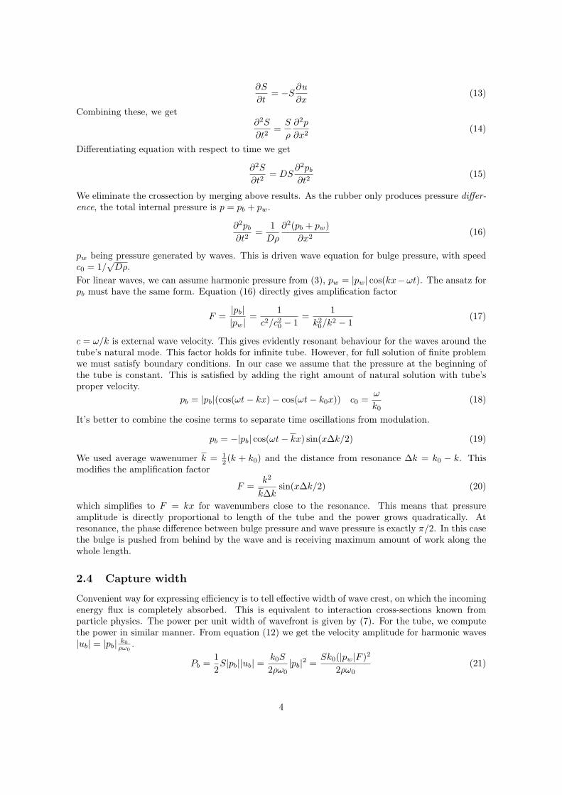
Figure 4: Bulge profile at resonant speed shows linear increase in amplitude along the length. The bulges onthe tube rides the waves in quarter phase in front of the wave crests and so collect the most energy. At wavespeeds far below resonance, the tube is only showing fluctuations in shape. (figure: gnuplot)
Finally we divide the results to obtain the capture width W .
W = 2k0SF 2 (22)
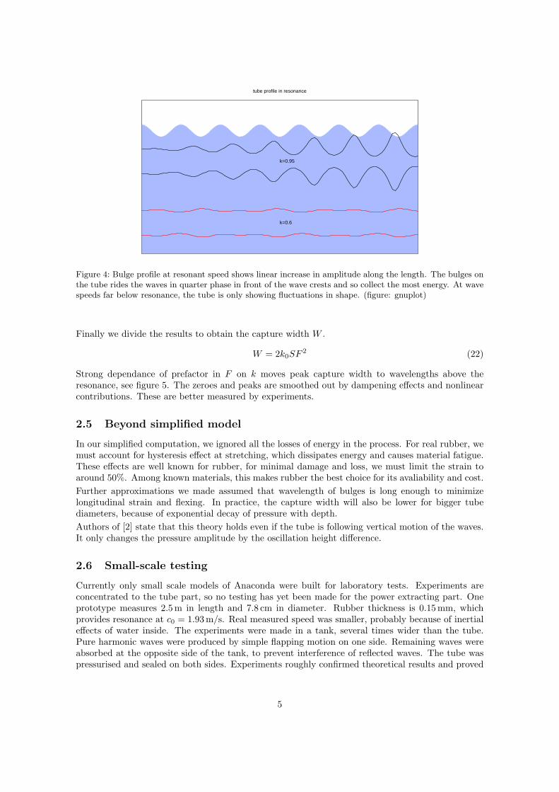
Strong dependance of prefactor in F on k moves peak capture width to wavelengths above theresonance, see figure 5. The zeroes and peaks are smoothed out by dampening effects and nonlinearcontributions. These are better measured by experiments.
2.5 Beyond simplified model
In our simplified computation, we ignored all the losses of energy in the process. For real rubber, wemust account for hysteresis effect at stretching, which dissipates energy and causes material fatigue.These effects are well known for rubber, for minimal damage and loss, we must limit the strain toaround 50%. Among known materials, this makes rubber the best choice for its avaliability and cost.Further approximations we made assumed that wavelength of bulges is long enough to minimizelongitudinal strain and flexing. In practice, the capture width will also be lower for bigger tubediameters, because of exponential decay of pressure with depth.Authors of [2] state that this theory holds even if the tube is following vertical motion of the waves.It only changes the pressure amplitude by the oscillation height difference.
2.6 Small-scale testing
Currently only small scale models of Anaconda were built for laboratory tests. Experiments areconcentrated to the tube part, so no testing has yet been made for the power extracting part. Oneprototype measures 2.5 m in length and 7.8 cm in diameter. Rubber thickness is 0.15 mm, whichprovides resonance at c0 = 1.93 m/s. Real measured speed was smaller, probably because of inertialeffects of water inside. The experiments were made in a tank, several times wider than the tube.Pure harmonic waves were produced by simple flapping motion on one side. Remaining waves wereabsorbed at the opposite side of the tank, to prevent interference of reflected waves. The tube waspressurised and sealed on both sides. Experiments roughly confirmed theoretical results and proved
5
Figure 5: Capture width for proposed dimensions of Anaconda. Oscillations are caused by interference ofexternal waves and bulge waves. Capture width is proportional to the square of amplification factor.
that losses are not problematic if we keep strains within reasonable limits. Further tests will showhow the materials behave in less-than-optimal weather conditions.
2.7 Full-scale
For big scale, the proposed dimensions would be 150m in length and 7 m thick. Tube of thissize would suffer more from vertical gradient of pressure, which hasn’t been investigated yet. Thethickness would need to be about 15 cm. It’s important to note that a one-way valve will be neededat the intake, to prevent negative pressures. The tube takes strain well, but the tube would collapseat negative pressures. This only biases the internal pressures and the strain, but doesn’t affectpropagation of waves.Anaconda will need active system for changing orientation into direction of waves. The intake endmust be pointed directly against the waves to achieve maximum power. Naturally, the tube woulddrift into the opposite direction.Ocean waves, suitable for harvesting, have periods around 10 s. However, the real spectrum of wavesis broader. The linear model, described above, gives average capture width of about W = 20m. Thisis much better than the best competition, which averages around 5 m. In Atlantic conditions withpower density 50 kW/m one tube would provide around 1 MW of power. Dependance of thicknesson radius ensures that the same amount of rubber is used if more tubes with smaller radius are usedin place of one bigger tube. Therefore the radius can be adapted to specific environments.The device would have two major uses. One uses bottom-mounted variety near the coast, and couldbe used for electricity production and for pumping seawater to the shore. Other option is arrayof bigger devices on the sea surface. In this variety, it would be suitable for mass production ofelectricity and connection to main power grid. Combination of both could be used for powering
6

Figure 6: Besides resonant behaviour around tube’s proper wavespeed, there are several other peaks corre-sponding to wavelengths matching with length of the tube. These peaks are at lower wavelength side of theresonance curve and are not predicted by equation (20) (see figure (3)). Crosses are computed from waveabsorbtion and circles are from pressure. [2]
desalinization plants.
2.8 Power take-off
For second stage, we must prepare steady pressure difference from the tube, to power the generator.The tube is producing irregular oscillatory pressure, which needs to be smoothed by some kindof low-pass filter. At this point we can use analogy with electrical circuits, where solution to theproblem is already known. The pressure stands for potential and the water flux corresponds withelectrical current. The electrical current on figure 7 (right) translates to a pair of valves (diodes),connected to reservoirs for high and low pressure water (capacitors). The turbine is then connectedbetween them, so that the water flows from high pressure to low pressure reservors with relativelysteady current. If depth of the device is variable, another reservoir should be added to providesmooth reference (ground in electrical analogy).
Figure 7: Stabilization of pressure and circuit analogue. The resistor represents internaal resistance of thetube. The turbine would be connected between the reservoirs.
7
2.9 Cost and profit
Not counting the generator, which is part of every power producing facility, the only capital cost ofAnaconda is the large amount of rubber, needed for the tube. Proposed size for operational version ofthe device is 150 m long and 7 m in diameter. This equals several hundred tons of rubber. Referringto [7], it would cost less than million pounds. If we assume output power 1 MW and £2M for totalconstruction, this gives about £2k/kW. The cheapest alternative among similiar devices is Pelamisby Ocean Power Delivery, which uses rigid raft-like design and extracts power at the joints. It costsat least three times per kilowatt of power.The smaller variation with 1.5 m diameter would produce 50 kW of power at slightly higher cost.
2.10 Advantages and disadvantages
This method for converting wave power into electricity is good for simplicity in low cost. No assemblyis required for the tube (except the optional valve). Once installed, there’s no maintenance needed,except for cleaning. For generator part we can use existing technology. It poses minimal risk forwildlife and shipping, in case the tube breaks off the mooring. The installation is easily expandableand mobile because there are no stationary parts and buildings. The main disadvantage is irregularpower outcome, which is a problem, common to all alternative energy sources, especially wind andsolar power. For this reason it can only serve as supporting source, like latter. Another option isto use it for powering remote places, like desalinisation plants and isolated settlements. Its usage islimited to the countries, open directly to oceans with steady wind conditions: mainly Atlantic coastand Australia. Only open sea has waves high enough to make Anaconda cost-efficient.
3 Vivace: exploiting vortex-induced vibration
Cylinders suspended in uniform stream, cause vortex street behind it if the speed of the stream ishigh enough. Vortices carry linear and angular momentum and thus put an oscillating pressure onthe cylinder. This can cause serious damage if the frequency resonates with the structure and weakenthe material even at small amplitudes. Common situations where this occurs are oil platforms andbridge supports. Famous example is the failure of Tacoma bridge in 1940. Undesired turbulenceeffects are countered by modifying the surface of the pillars and adding additional pillars at specificpositions in the stream.Pax research institute is developing a system, called Vivace (Vortex-induced vibration for aquaticclean energy). Their attempt is to use vortex-induced vibrations to run a generator and producepower. For now, their design uses the simplest variation of theoretical model. The active part is justa vertically oscillating cylinder.
3.1 Karman vortex street
In twodimensional approximation and inviscid fluid, periodic pattern of alternating vortices can beanalitically obtained. The aspect ratio of the street is uniquely determined. However, the separationbetween vortices and the frequency of shedding is strongly dependant of the viscosity and the objectwhich causes the original disturbance. For given Reynolds number Re = ud/η (η is kinematicviscosity), we define the nondimensional frequency as Strouhal number.
St = νd
u
d is diameter of the cylinder and u is fluid velocity far from the active area. This number howeverhas very complex dependance on Re and is obtained through measurements in controlled conditions,
8
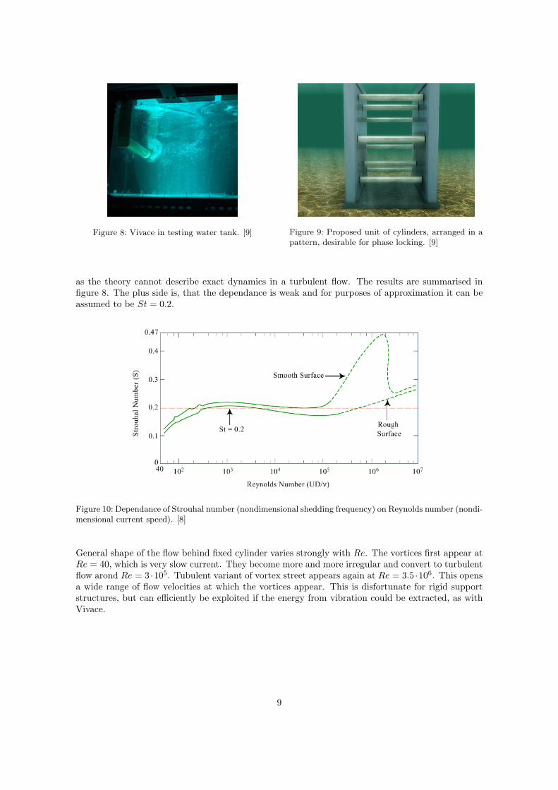
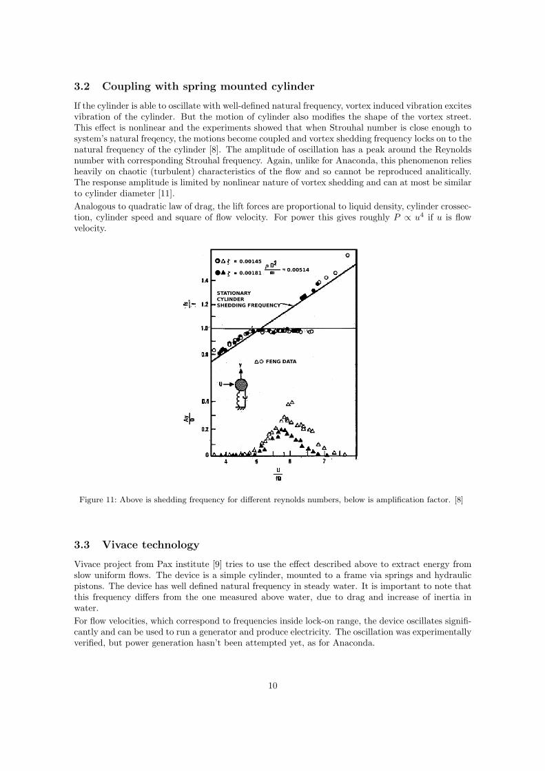
Figure 8: Vivace in testing water tank. [9] Figure 9: Proposed unit of cylinders, arranged in apattern, desirable for phase locking. [9]
as the theory cannot describe exact dynamics in a turbulent flow. The results are summarised infigure 8. The plus side is, that the dependance is weak and for purposes of approximation it can beassumed to be St = 0.2.
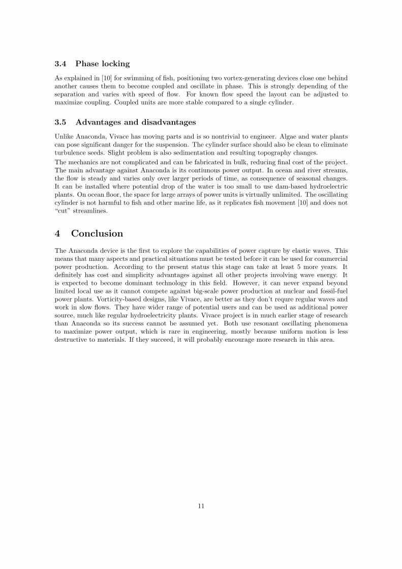
Figure 10: Dependance of Strouhal number (nondimensional shedding frequency) on Reynolds number (nondi-mensional current speed). [8]
General shape of the flow behind fixed cylinder varies strongly with Re. The vortices first appear atRe = 40, which is very slow current. They become more and more irregular and convert to turbulentflow arond Re = 3 ·105. Tubulent variant of vortex street appears again at Re = 3.5 ·106. This opensa wide range of flow velocities at which the vortices appear. This is disfortunate for rigid supportstructures, but can efficiently be exploited if the energy from vibration could be extracted, as withVivace.
9
3.2 Coupling with spring mounted cylinder
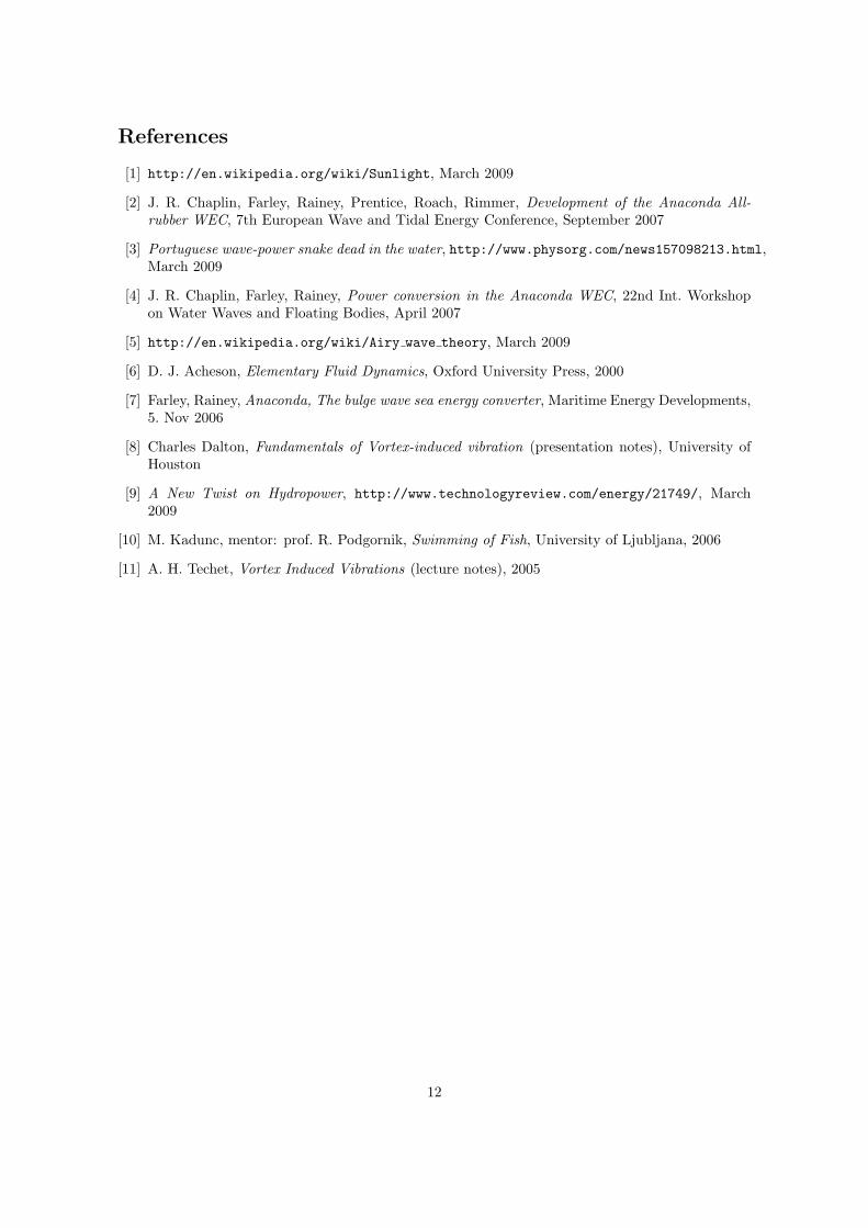
If the cylinder is able to oscillate with well-defined natural frequency, vortex induced vibration excitesvibration of the cylinder. But the motion of cylinder also modifies the shape of the vortex street.This effect is nonlinear and the experiments showed that when Strouhal number is close enough tosystem’s natural freqency, the motions become coupled and vortex shedding frequency locks on to thenatural frequency of the cylinder [8]. The amplitude of oscillation has a peak around the Reynoldsnumber with corresponding Strouhal frequency. Again, unlike for Anaconda, this phenomenon reliesheavily on chaotic (turbulent) characteristics of the flow and so cannot be reproduced analitically.The response amplitude is limited by nonlinear nature of vortex shedding and can at most be similarto cylinder diameter [11].Analogous to quadratic law of drag, the lift forces are proportional to liquid density, cylinder crossec-tion, cylinder speed and square of flow velocity. For power this gives roughly P ∝ u4 if u is flowvelocity.
Figure 11: Above is shedding frequency for different reynolds numbers, below is amplification factor. [8]
3.3 Vivace technology
Vivace project from Pax institute [9] tries to use the effect described above to extract energy fromslow uniform flows. The device is a simple cylinder, mounted to a frame via springs and hydraulicpistons. The device has well defined natural frequency in steady water. It is important to note thatthis frequency differs from the one measured above water, due to drag and increase of inertia inwater.For flow velocities, which correspond to frequencies inside lock-on range, the device oscillates signifi-cantly and can be used to run a generator and produce electricity. The oscillation was experimentallyverified, but power generation hasn’t been attempted yet, as for Anaconda.
10
3.4 Phase locking
As explained in [10] for swimming of fish, positioning two vortex-generating devices close one behindanother causes them to become coupled and oscillate in phase. This is strongly depending of theseparation and varies with speed of flow. For known flow speed the layout can be adjusted tomaximize coupling. Coupled units are more stable compared to a single cylinder.
3.5 Advantages and disadvantages
Unlike Anaconda, Vivace has moving parts and is so nontrivial to engineer. Algae and water plantscan pose significant danger for the suspension. The cylinder surface should also be clean to eliminateturbulence seeds. Slight problem is also sedimentation and resulting topography changes.The mechanics are not complicated and can be fabricated in bulk, reducing final cost of the project.The main advantage against Anaconda is its contiunous power output. In ocean and river streams,the flow is steady and varies only over larger periods of time, as consequence of seasonal changes.It can be installed where potential drop of the water is too small to use dam-based hydroelectricplants. On ocean floor, the space for large arrays of power units is virtually unlimited. The oscillatingcylinder is not harmful to fish and other marine life, as it replicates fish movement [10] and does not“cut” streamlines.
4 Conclusion
The Anaconda device is the first to explore the capabilities of power capture by elastic waves. Thismeans that many aspects and practical situations must be tested before it can be used for commercialpower production. According to the present status this stage can take at least 5 more years. Itdefinitely has cost and simplicity advantages against all other projects involving wave energy. Itis expected to become dominant technology in this field. However, it can never expand beyondlimited local use as it cannot compete against big-scale power production at nuclear and fossil-fuelpower plants. Vorticity-based designs, like Vivace, are better as they don’t requre regular waves andwork in slow flows. They have wider range of potential users and can be used as additional powersource, much like regular hydroelectricity plants. Vivace project is in much earlier stage of researchthan Anaconda so its success cannot be assumed yet. Both use resonant oscillating phenomenato maximize power output, which is rare in engineering, mostly because uniform motion is lessdestructive to materials. If they succeed, it will probably encourage more research in this area.
11
References
[1] http://en.wikipedia.org/wiki/Sunlight, March 2009
[2] J. R. Chaplin, Farley, Rainey, Prentice, Roach, Rimmer, Development of the Anaconda All-rubber WEC, 7th European Wave and Tidal Energy Conference, September 2007
[3] Portuguese wave-power snake dead in the water, http://www.physorg.com/news157098213.html,March 2009
[4] J. R. Chaplin, Farley, Rainey, Power conversion in the Anaconda WEC, 22nd Int. Workshopon Water Waves and Floating Bodies, April 2007
[5] http://en.wikipedia.org/wiki/Airy wave theory, March 2009
[6] D. J. Acheson, Elementary Fluid Dynamics, Oxford University Press, 2000
[7] Farley, Rainey, Anaconda, The bulge wave sea energy converter, Maritime Energy Developments,5. Nov 2006
[8] Charles Dalton, Fundamentals of Vortex-induced vibration (presentation notes), University ofHouston
[9] A New Twist on Hydropower, http://www.technologyreview.com/energy/21749/, March2009
[10] M. Kadunc, mentor: prof. R. Podgornik, Swimming of Fish, University of Ljubljana, 2006
[11] A. H. Techet, Vortex Induced Vibrations (lecture notes), 2005
12