micro hydroelectricity installer skills...
TRANSCRIPT
Micro Hydroelectricity Installer Skills Assessment Renewable Energy Training Center Morrisville State College
Page 1
Micro Hydroelectricity Installer Skills Assessment
Philip V. Hofmeyer
Renewable Energy Training Center Morrisville State College
August 2011

Micro Hydroelectricity Installer Skills Assessment Renewable Energy Training Center Morrisville State College
Page 2
Overview: This document contains an extensive skills assessment for renewable energy professionals who intend to design, install, commission, and maintain micro hydroelectricity systems. This skills assessment pertains to grid-interactive and stand-alone micro hydro systems and focuses on installations primarily intended for use in the United States, though much of the document has applicability beyond the United States. Assessment Scope: There are many definitions available for “micro” hydroelectricity systems, ranging up to 100 kW in size. It should be noted that the skills identified in this document are intended for use in residential and small commercial hydro systems for on-site energy production, perhaps up to 5 kW in generator capacity. Beyond that level, the requirements for civil engineering, environmental permitting, and electrical permitting quickly exceed the range of a typical renewable energy installer, similar to larger wind energy systems. Skills assessed for this document are primarily for run-of-river hydro systems, though very small storage systems will be addressed. The intent of this document is not on large impoundment design, as the environmental impacts and sustainability of those projects quickly come into question. Though there is no nationally recognized certifying body for micro hydroelectricity systems (e.g. The North American Board of Certified Energy Practitioners (NABCEP) for small wind and solar energy systems) and no nationally recognized test to prepare for, this document outlines a similar group of skills needed for an installer to approach a project. This will help to establish criteria and requirements for educational institutions intending to train students in micro hydroelectricity. Additionally, the National Electrical Code does not specify a section for micro hydroelectricity installations. Therefore, it will be assumed that the Authority Having Jurisdiction will refer primarily to Articles 690 (Solar Photovoltaic Systems), 694 (Small Wind Electric Systems), and 705 (Interconnected Electric Power Production Sources) in addition to generally applied Articles not specified in Chapter 6 “Special Equipment.” This skills assessment outlines tasks in the following areas: site assessment, system design, civil installation, electrical installation, permitting, commissioning, and maintenance and troubleshooting. A list of tools and general knowledge areas are also included. This document is not intended to outline the tasks necessary for marketing and sales of micro hydroelectricity systems, nor address the cost effectiveness of these systems.
Micro Hydroelectricity Installer Skills Assessment Renewable Energy Training Center Morrisville State College
Page 3
Table of Contents
Overview ............................................................................................................................. 2 Assessment Scope ............................................................................................................... 2
1. Site Assessment ........................................................................................................... 4 1.1. Conducting an Energy Assessment ........................................................................ 4 1.2. Conducting a Site Survey ...................................................................................... 4
2. System Design ............................................................................................................. 5 2.1. Determine the Turbine Components ..................................................................... 5 2.2. Sizing the Penstock ............................................................................................... 5 2.3. Sizing Electrical Components ............................................................................... 5
2.3.1. Battery-based Systems ............................................................................. 6
3. Installation ................................................................................................................... 7 3.1. Install Intake.......................................................................................................... 7 3.2. Install Penstock Components ................................................................................ 7 3.3. Install Electrical Components ............................................................................... 7
3.3.1. Install Battery Components ..................................................................... 8 3.4. Install Turbine ....................................................................................................... 9
4. Commissioning .......................................................................................................... 10 4.1. Penstock Commissioning .................................................................................... 10 4.2. Electrical Commissioning ................................................................................... 10
5. Troubleshooting and Maintenance ............................................................................ 11 5.1. Penstock Troubleshooting ................................................................................... 11 5.2. Turbine Troubleshooting .................................................................................... 11 5.3. Electrical Troubleshooting .................................................................................. 11
6. Micro Hydroelectricity Knowledge Base .................................................................. 12 6.1. Tools ................................................................................................................... 12 6.2. General Knowledge ............................................................................................ 12
Micro Hydroelectricity Installer Skills Assessment Renewable Energy Training Center Morrisville State College
Page 4
1. Site Assessment
1.1. Conducting an Energy Assessment Review client’s utility bills Determine client’s electricity expectations Determine client’s energy cost expectations Perform a load assessment (stand-alone and commercial systems only) Determine client’s budget Address interconnection concerns Review net metering with client (grid-interactive systems only) Suggest electricity efficiency and conservation measures to client Measure resting voltage and frequency at client’s point of connection with the utility Evaluate existing service entrance equipment
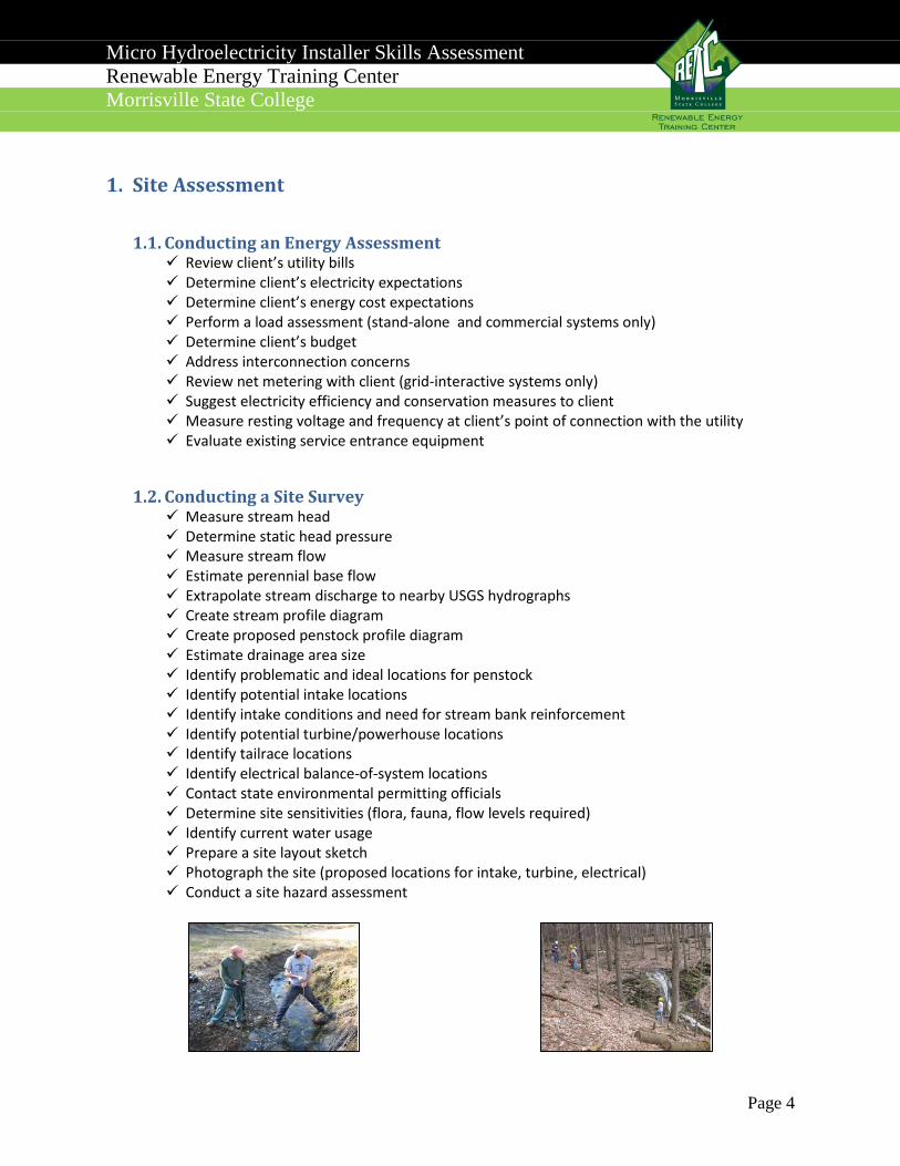
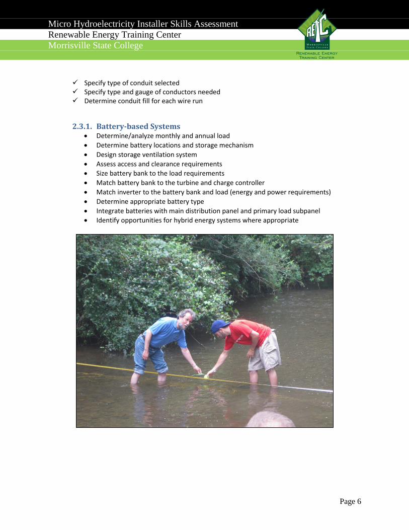
1.2. Conducting a Site Survey Measure stream head Determine static head pressure Measure stream flow Estimate perennial base flow Extrapolate stream discharge to nearby USGS hydrographs Create stream profile diagram Create proposed penstock profile diagram Estimate drainage area size Identify problematic and ideal locations for penstock Identify potential intake locations Identify intake conditions and need for stream bank reinforcement Identify potential turbine/powerhouse locations Identify tailrace locations Identify electrical balance-of-system locations Contact state environmental permitting officials Determine site sensitivities (flora, fauna, flow levels required) Identify current water usage Prepare a site layout sketch Photograph the site (proposed locations for intake, turbine, electrical) Conduct a site hazard assessment
Micro Hydroelectricity Installer Skills Assessment Renewable Energy Training Center Morrisville State College
Page 5
2. System Design
2.1. Determine the Turbine Components Evaluate the client’s budget Evaluate the client’s energy needs Determine size, make, and model of generator Determine number and size of nozzles required Determine water exit strategy and tailrace design
2.2. Sizing the Penstock Determine penstock diameter Determine penstock materials Estimate static head pressure Estimate dynamic head pressure (normal operating conditions) Estimate surge head pressure (water hammer conditions) Match pressure relief valve to static, dynamic, and surge pressure calculations Identify appropriate pressure gauge Determine appropriate valves and locations (e.g. gate or butterfly valves) Locate vacuum relief location Determine cleanout and vent locations Size the intake for flow and stream conditions Reinforce intake headrace and wing walls (where appropriate) Determine final location for intake Determine locations for penstock thrust blocks Determine freeze protection plan (where appropriate)
2.3. Sizing Electrical Components Determine operating temperature minimum and maximum Match inverter (and/or charge controller) with turbine Determine appropriate diversion load Determine distance of each wire run Determine voltage drop of conductors Determine ampacity of conductors Select DC disconnect(s) and their locations Select AC disconnect(s) and their locations Determine grounding and bonding strategy Determine EGC and ECG conductor sizes needed Specify overcurrent protection Determine ground-fault protection devices
Micro Hydroelectricity Installer Skills Assessment Renewable Energy Training Center Morrisville State College
Page 6
Specify type of conduit selected Specify type and gauge of conductors needed Determine conduit fill for each wire run
2.3.1. Battery-based Systems • Determine/analyze monthly and annual load • Determine battery locations and storage mechanism • Design storage ventilation system • Assess access and clearance requirements • Size battery bank to the load requirements • Match battery bank to the turbine and charge controller • Match inverter to the battery bank and load (energy and power requirements) • Determine appropriate battery type • Integrate batteries with main distribution panel and primary load subpanel • Identify opportunities for hybrid energy systems where appropriate
Micro Hydroelectricity Installer Skills Assessment Renewable Energy Training Center Morrisville State College
Page 7
3. Installation
3.1. Install Intake Secure permits necessary for stream disturbance Secure zoning permits necessary for construction Locate appropriate intake site Protect intake from high spring discharge Provide access for regular intake maintenance Secure intake to streambed Provide plan for siltation and debris removal Secure intake against ice flows (where appropriate) Match intake screen pore size with nozzle diameter Install settling basin (where appropriate) Install reinforcement wing walls (where appropriate) Identify potential stream use conflicts with intake scheme
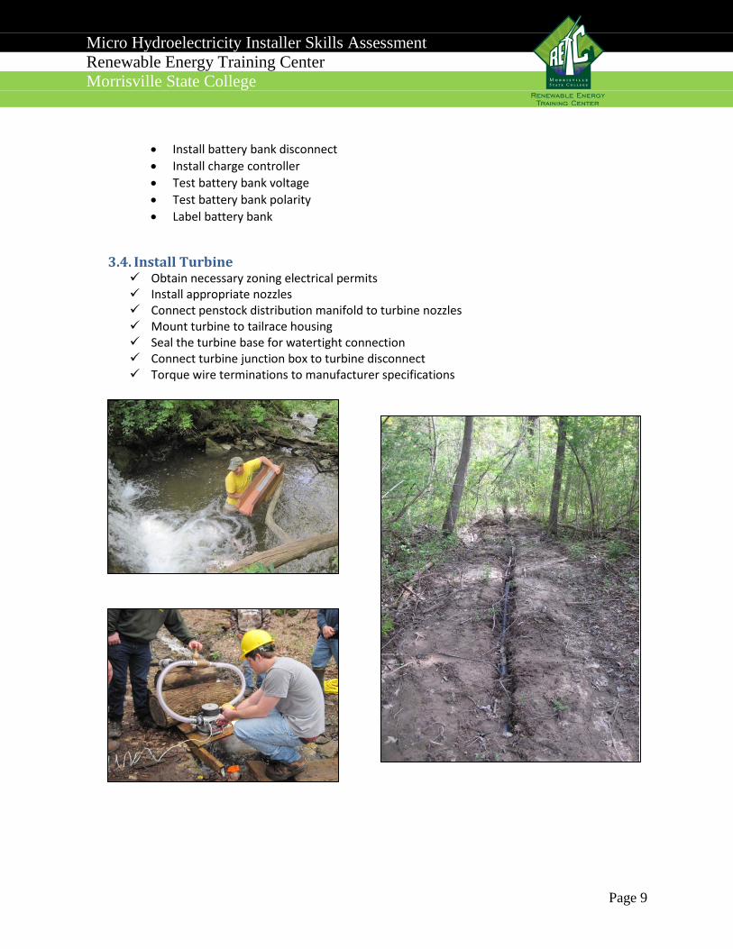
3.2. Install Penstock Components Secure permits necessary for stream disturbance Secure zoning permits necessary for construction Create installation safety plan to mitigate hazards Utilize appropriate PPE Locate appropriate course for penstock run Excavate the penstock run for buried applications Call 811 before site excavations Connect penstock to intake Determine penstock section joining methods and materials Install vacuum relief Install intake valves Install cleanout mechanism Install pressure gauge Install pressure relief valve Install distribution manifold Connect manifold to turbine nozzles Install thrust blocks Backfill penstock run Install tailrace back to water course Trench and backfill tailrace for buried applications Install midway purge and cleanout valves where appropriate
3.3. Install Electrical Components Obtain necessary interconnection permits Obtain necessary FERC permits
Micro Hydroelectricity Installer Skills Assessment Renewable Energy Training Center Morrisville State College
Page 8
Obtain necessary zoning electrical permits Create an electrical safety plan to mitigate hazards Utilize appropriate PPE Utilize lock-out, tag-out plan Disconnect all live circuits that could be hazardous during installation Mount DC disconnect(s) in final location Mount AC disconnect(s) in final location Mount inverter in final location Mount charge controller in final location Mount diversion load in final location Mount AC kWh meter in final location Mount junction boxes in final location Determine grounding conductor sizes Install turbine grounding (EGC) Install inverter grounding (EGC) Install ground rods and make grounding electrode connection (GEC) Bond all BOS chassis components (EGC) Bond all conduit and raceways Test continuity and resistance of intended ground-fault current path Plan conduit type and routing Install conduit and supports at appropriate intervals Tighten all conduit fittings Knockout appropriate raceway and junction box orifices Pull conductors Label all conductors at point of termination Wire the turbine disconnect Wire the diversion load Wire the AC and DC inverter disconnects Wire the Inverter Wire the kWh meter Wire the branch load breaker (or other utility OCPD) in Main Distribution Panel Torque conductor terminations to manufacturer specifications Check termination torques Label all power sources, disconnects, junction boxes, and potentially energized circuits Create an “as-built” wiring line diagram
3.3.1. Install Battery Components • Install battery enclosure • Install appropriate venting system • Install spill containment for the selected battery type • Install batteries • Clean battery terminals • Install battery jumper wires (series and parallel connections)
Micro Hydroelectricity Installer Skills Assessment Renewable Energy Training Center Morrisville State College
Page 9
• Install battery bank disconnect • Install charge controller • Test battery bank voltage • Test battery bank polarity • Label battery bank
3.4. Install Turbine Obtain necessary zoning electrical permits Install appropriate nozzles Connect penstock distribution manifold to turbine nozzles Mount turbine to tailrace housing Seal the turbine base for watertight connection Connect turbine junction box to turbine disconnect Torque wire terminations to manufacturer specifications

Micro Hydroelectricity Installer Skills Assessment Renewable Energy Training Center Morrisville State College
Page 10
4. Commissioning
4.1. Penstock Commissioning Fill penstock and purge air Drain line to ensure proper vacuum relief operation Purge pressure gauge chamber Verify expected static pressure Investigate all penstock mechanical joints and splicing for leaks Test pressure relief valve Verify expected flow and dynamic pressure Adjust nozzle diameter if required
4.2. Electrical Commissioning Wear appropriate PPE for live electrical testing Verify system grounding continuity Verify turbine output polarity Measure turbine voltage Measure turbine amperage Calculate system power output Compare measured values with expected output values Start up inverter per manufacturer protocol Set inverter parameters Verify inverter anti-islanding Verify diversion load startup upon grid disconnect Verify inverter output Test for unwanted current on the grounding conductors Verify labeling and make changes if necessary Verify as-built electrical diagram Verify system kWh meter operation
Micro Hydroelectricity Installer Skills Assessment Renewable Energy Training Center Morrisville State College
Page 11
5. Troubleshooting and Maintenance
5.1. Penstock Troubleshooting Interview client and document concerns Inspect joints for leaking water Verify no back pressure at tailrace Compare pressure gauge reading to expected value Expel water from pressure relief valve Increase flow to remove trapped air Purge air from localized high spots in the penstock Cleanout accumulated silt in localized low spots in the penstock Remove silt and other debris from intake Verify intake attachment to streambed Verify intake submerged Identify water intake patterns (e.g. air entering penstock during low flow periods) Verify corrective actions
5.2. Turbine Troubleshooting Interview client and document concerns Measure turbine output (voltage, amperage, power) Compare measured output results to expected values Compare estimated kWh output to kWh meter reading Inspect/replace turbine bearings Inspect nozzle debris accumulation Verify runner balance Perform recommended maintenance Verify corrective actions
5.3. Electrical Troubleshooting Interview client and document concerns Measure turbine output (voltage, amperage, power) Compare measured output results to expected values Check for ground-fault current Repair ground faults Check inverter set points Replace damaged conductors Replace blown fuses Check conductor termination torques Repair junction box weatherproofing Replace missing system labels Verify corrective actions
Micro Hydroelectricity Installer Skills Assessment Renewable Energy Training Center Morrisville State College
Page 12
6. Micro Hydroelectricity Knowledge Base Micro hydroelectricity installers must be familiar with a broad spectrum of tools and knowledge. A list of these skills and tools is below.
6.1. Tools Clinometer Compass Digital mapping software Distance tape Head loss charts Heavy equipment HDPE heat fusion equipment (butt and socket fusion) Multimeter Nozzle charts Oscilloscope Pipe fitting wrenches Power hand tools Pressure gauge Residential energy meter Spreadsheet software Strap wrench Surveying equipment Topographic map Torque driver Torque wrench Utility bill
6.2. General Knowledge ANSI grid standards Basic construction Battery bank sizing Charge controller profiles Climate and weather data Communications and data wiring Concrete foundations Data logging Digital mapping Electrical calculations (voltage drop, ampacity, etc.) Electrical line diagrams Energy from power and time Gabion walls Hazard assessment and mitigation
Micro Hydroelectricity Installer Skills Assessment Renewable Energy Training Center Morrisville State College
Page 13
Head loss calculations Heavy equipment operation Incentives Intake wing walls Inverter voltage and amperage limitations Local zoning permitting process Motors and generators National Electrical Code Nozzle diameter calculations Ohm’s Law OSHA requirements Pipe fittings Pipe fusion (HDPE and PVC) Power and energy Power Law Pulse-width modulation Residential electricity Site plans Soils classifications State permitting Trigonometry Turbine output characteristics Utility interconnection requirements Water power Weirs
This project was funded by a grant awarded under the President's Community-Based Job Training Grants, as implemented by the U.S. Department of Labor's Employment and Training Administration.