seismic performance of chevron braced steel frames with .... dicleli, a. mehta / journal of...
TRANSCRIPT
Journal of Constructional Steel Research 63 (2007) 1102–1115www.elsevier.com/locate/jcsr
Seismic performance of chevron braced steel frames with and withoutviscous fluid dampers as a function of ground motion and damper
characteristics
Murat Diclelia,∗, Anshu Mehtab
a Department of Engineering Sciences, Middle East Technical University, 06531 Ankara, Turkeyb Department of Civil Engineering and Construction, Bradley University, Peoria, IL 61625, United States
Received 10 May 2006; accepted 19 September 2006
Abstract
This study is aimed at comparing the seismic performance of steel chevron braced frames (CBFs) with and without viscous fluid dampers(VFDs) as a function of the intensity and frequency characteristics of the ground motion and VFD parameters. For this purpose, comparativenonlinear time history (NLTH) analyses of single and multiple story CBFs with and without VFDs are conducted using ground motions withvarious frequency characteristics scaled to represent small, moderate and large intensity earthquakes. Additionally, NLTH analyses of singleand multiple story CBFs with VFDs are conducted to study the effect of the damping ratio and velocity exponent of the VFD on the seismicperformance of the frames. The analysis results revealed that the seismic performance of the CBFs without VFDs is very poor and sensitive to thefrequency characteristics and intensity of the ground motion due to brace buckling effects. Installing VFDs into the CBFs significantly improvedtheir seismic performance by maintaining their elastic behavior. Furthermore, VFDs with smaller velocity exponents and larger damping ratio areobserved to be more effective in improving the seismic performance of the CBFs. However, VFDs with damping ratios larger than 50% do notproduce significant additional improvement in the seismic performance of the CBFs.c© 2006 Elsevier Ltd. All rights reserved.
Keywords: Steel; Frames; Bracing; Viscous fluid damper; Seismic
1. Introduction
In steel buildings, one of the most commonly used steelbraced frame type is a chevron braced frame (CBF) since itsbrace configuration provides an open space for architecturalarrangements. Seismic energy dissipation in a CBF solelydepends on the nonlinear cyclic response of the braces. Cyclicaxial force–deformation behavior of a brace is unsymmetricin tension and compression and typically exhibits substantialstrength and stiffness deterioration due to buckling effects [1].Thus, when subjected to a strong ground motion, inelasticbuckling of the braces in a CBF results in loss of lateralstiffness and strength of the frame [2]. Furthermore, it isdifficult to achieve well-distributed ductility demands along theheight of the CBF due to the premature buckling of the braces
∗ Corresponding author. Tel.: +90 312 210 4451; fax: +90 312 210 4462.E-mail address: [email protected] (M. Dicleli).
0143-974X/$ - see front matter c© 2006 Elsevier Ltd. All rights reserved.doi:10.1016/j.jcsr.2006.09.005
at certain floor levels [3] resulting in soft-story formations,dynamic instability [4] and hence substantial damage to theframe members.
Because of the above-mentioned poor performance charac-teristics, a large number of CBFs suffered considerable damagein past earthquakes [5–10]. Consequently, numerous researchstudies have been initiated in recent years to improve the perfor-mance of CBFs through the introduction of new structural con-figurations [2,11], the use of high performance materials [12],buckling restrained braces [1] as well as passive energy dissi-pation devices such as hysteretic [13], friction [14] and viscousfluid dampers (VFDs) [15–17]. Among all these seismic perfor-mance improvement techniques, using VFDs in a structure hasthe unique advantage of reducing the structure base shear forceand deflections at the same time since the velocity-dependentmaximum VFD force is out of phase with the maximum deflec-tion of the structure [17]. Furthermore, the addition of VFDsinto a structure does not alter the force–displacement relation-

M. Dicleli, A. Mehta / Journal of Constructional Steel Research 63 (2007) 1102–1115 1103
ship and hence the dynamic modal characteristics of the struc-ture [18]. Consequently, VFDs seem to be viable tools for im-proving the seismic performance of CBFs.
Many research studies concerning the effect of VFDs onthe seismic performance of building structures have beenconducted in the past [16–20]. However, a comparative researchstudy on the seismic performance of CBFs with and withoutVFDs as a function of ground motion and damper parametersis scarce. Thus, this study focuses on comparing the seismicperformance of CBFs with and without VFDs as a function ofthe intensity and frequency characteristics of the ground motionas well as the damping ratio and velocity exponent of theVFD. The results from such a research study may then be usedto measure the efficiency of VFDs for improving the seismicperformance of CBFs as a function of the ground motioncharacteristics and VFD parameters and arrive at importantdecisions related to the seismic retrofitting and design of CBFsusing VFDs.
2. Background
Seismic performance of CBFs has been studied by manyresearchers [1–4]. From these research studies it was found thatenergy dissipation in CBFs depends on the unstable nonlinearresponse of the braces [1] that may result in loss of lateralstiffness and strength of the frame [2]. Furthermore, it wasconcluded that it is difficult to achieve well distributed ductilitydemands along the height of the CBF [4] due to prematurebuckling of the braces at certain floor levels [3].
To alleviate the effect of these poor performance character-istics, many research studies have been conducted. Khatib et al.[2] introduced a new structural configuration called a “zipperframe”. It was found that the “zipper frame” configuration re-sulted in simultaneous buckling of the braces at all story lev-els and hence a well distributed energy dissipation along theheight of the frame. Dicleli and Mehta [11] introduced a verti-cal shear link between the chevron braces and the frame beamto improve the performance of the CBFs. It was found thatthe yielding of the shear link prior to buckling of the bracesresulted in a more stable cyclic lateral force–deformation be-havior and a better energy dissipation mechanism. Wilson andWesolowsky [12] conducted an extensive state-of-the-art re-view of the application of shape memory alloys for seismic re-sponse modification of structures. It was found that such high-tech materials could be used successfully in steel braced framesto improve their seismic performance. Analytical studies haverevealed that shape memory alloys may reduce the inter-storydrift of braced frames by as much as 50%. However, the onenoted drawback was the increase in acceleration, as high as200% at some story levels. Sabelli et al. [1] studied the effectof installing buckling-restrained braces in CBFs on the seismicresponse of such frames. It was found that buckling-restrainedbraces provide an effective means for overcoming many of thepotential problems associated with special CBFs. Passive en-ergy dissipation devices such as hysteretic [13], friction [14]and viscous fluid dampers (VFDs) [15–17] have also been usedto improve the seismic performance of steel frames. However,
using VFDs in a structure was found to have the unique advan-tage of reducing the structure base shear force and deflectionsat the same time [17].
Many research studies concerning the effect of VFDs onthe seismic performance of building structures have beenconducted in the past [16–20]. Constantinou and Symans [15,16] and Tsai et al. [19] conducted experimental and analyticalstudies on the seismic response of steel buildings with VFDs.It was concluded that the inclusion of VFDs in the testedstructures resulted in reductions in story drifts of 30%–70%and story shear forces of 40%–70%. It was also concluded thatVFDs reduced column bending moments, while introducingadditional column axial forces out-of-phase with the bendingmoments. Thus, it was suggested that this behavior preventsthe compression failure of weak columns in retrofittingapplications. Martinez-Rodrigo and Romero [18] conductedanalytical research studies to build a simple methodologyleading to an optimum retrofitting option for moment resistingframes with linear and nonlinear VFDs. It was observed thatfor close to unity values of the nonlinear velocity exponent,the envelope of the response remains almost constant whilethe forces in the dampers are effectively reduced from thelinear case. The maximum force experienced by the dampersin the nonlinear case may be reduced by more than 35%in comparison with the linear retrofitting case with a similarstructural seismic performance. Uriz and Whittaker [20]investigated the use of linear fluid viscous damping devices forthe seismic retrofit of a three-story, pre-Northridge steel-framedbuilding. It was found that using VFDs with an equivalentviscous damping of 40% of critical resulted in reductions in thedisplacement of the frame by a factor exceeding two. However,although plastic rotations in the beams were substantiallyreduced, they were not totally eliminated.
3. Research objective and outline
The main objective of the present research study is toinvestigate the effect of VFDs on the seismic performanceof CBFs as a function of the intensity and frequencycharacteristics of the ground motion and VFD parameters.For this purpose, first, an analytical brace-buckling model isdeveloped to simulate the inelastic cyclic behavior of the bracesin CBFs using the finite element based program ADINA [21].Next, 84 comparative nonlinear time history (NLTH) analysesof single two, four and eight story CBFs with and without VFDsare conducted using seven seismic ground motions with variousfrequency characteristics scaled to represent small, moderateand large intensity earthquakes. These comparative analysesare performed mainly to study the effect of the ground motionproperties and the number of stories on the seismic performanceof CBFs with and without VFDs. Subsequently, 224 additionalNLTH analyses of single and four story CBFs with VFDs areconducted to study the effect of the damping ratio and velocityexponent of the VFD on the seismic performance of the frames.In the last phase of the research, practical implications of usingVFDs in CBFs are outlined and important conclusions andrecommendations collected from the NLTH analyses results aresummarized.

1104 M. Dicleli, A. Mehta / Journal of Constructional Steel Research 63 (2007) 1102–1115
Fig. 1. (a) Frame models. (b) Acceleration response spectra of the earthquakes used in the analyses.
4. Details of the frames considered for analyses
The details of the one, two, four and eight-story framesconsidered for NLTH analyses are demonstrated in Fig. 1(a).The frame members are numbered from 1 to 11 and theirsizes are tabulated across each number in the same figure.First, the eight-story frame is configured such that each two-story levels have the same member sizes, the lateral strengthof the frame gradually decreases at the higher story levelsand the frame exhibits nonlinear behavior under moderateto high intensity ground motions. The design of the frameis performed using the AISC Load and Resistance FactorDesign Specifications for Structural Steel Buildings [22] usingweak beam–strong column approach for seismic resistance andignoring the vertical support provided by the chevron bracesto the beams for gravitational load design per current state ofpractice. The beams are assumed to be rigidly connected tothe columns. The frame members are assumed to be made of
ASTM A36 steel with yield strength of 248 MPa and modulusof elasticity of 200 000 MPa, while the tubular braces areassumed to be made of ASTM A500 Grade B steel with yieldstrength of 318 MPa. The one, two and four-story frames arethen assumed to form the bottom one, two and four stories of theeight-story frame respectively. This was done to solely study theperformance of the CBFs with and without VFDs as a functionof the number of stories. The elastic and modal properties ofthe frames which are the elastic stiffness and elastic limit (topdisplacement) based on a triangular lateral load distribution aswell as the modal periods, T1, T2, T3 corresponding to the firstthree lateral vibration modes are provided in Table 2. For theCBFs with VFDs, the dampers are assumed to be mountedalong the existing chevron braces. A typical VFD arrangementis illustrated on the single story frame in Fig. 1(a). Similardamper arrangements (damper installed along the brace) havealso been used in the studies of Constantinou and Symans [15]and Martinez-Rodrigo and Romero [18]. It is worth mentioning

M. Dicleli, A. Mehta / Journal of Constructional Steel Research 63 (2007) 1102–1115 1105
that a damper arrangement where the dampers are mountedparallel to the beam at the top of the chevron braces may offeradditional benefits. In such a damper arrangement, the dampersare generally subjected to higher relative velocities and henceproduce better energy dissipation and resistance to seismicforces. However, the damper arrangement used in this study ischosen as it is generally more suitable for seismic retrofittingapplications of CBF.
5. Ground motions considered for analyses
Seismic ground motions are generally characterized bytheir peak ground acceleration, Ap, to peak ground velocity,Vp, ratios [23] which represent their dominant frequency andenergy content. Ground motions with intense long-durationacceleration pulses have low Ap/Vp ratios, whereas thosewith high frequency, short-duration acceleration pulses havehigh Ap/Vp ratios. Consequently, ground motions with variousAp/Vp ratios are considered to assess the performance of theCBFs with and without VFDs for a wide range of groundmotion characteristics. For this purpose, a set of seven groundmotions with Ap/Vp ratios ranging between 5.5 and 21.5 s−1
are considered (Table 1). The acceleration response spectra ofthe ground motions are presented in Fig. 1(b). The groundmotions are scaled to have Ap = 0.20g, 0.35g and 0.50grepresenting respectively, small, moderate and large intensityearthquakes.
6. Brief review of viscous fluid dampers
VFDs operate on the principle of fluid flow through orifices.Details of a typical VFD are illustrated in Fig. 2(a). A VFDconsists of a piston within a damper-housing filled with acompound of compressible silicone fluid. The piston headcontains a number of small orifices through which the fluidpasses from one side of the piston to the other. Thus, the VFDdissipates the earthquake input energy through the movementof a piston in a highly viscous fluid based on the concept offluid orificing [24]. The force, F , in a VFD is calculated as;
F = CV α (1)
where C is the damping constant, V is the velocity at whichthe damper is oscillating and α is the velocity exponent. Anidealized force–displacement loop of a VFD is presented inFig. 2(b). The simplest form of VFD is a linear VFD, for whichthe velocity exponent, α, is equal to 1.0. Typical values of α
range between 0.5 and 2.0 [25]. VFDs with α larger than 1.0 aregenerally not used in seismic design applications. Those with α
smaller than 1.0 are called nonlinear VFDs.For a multiple story CBF with VFDs mounted diagonally
along the chevron braces, the damping ratio, ζk , of the frame atthe kth mode of vibration is expressed as [15];
ξk =
∑j
C j cos2 θ(φ j − φ j−1)2
2ωk∑
jm jφ
2j
(2)
Fig. 2. (a) Typical detail of a viscous fluid damper. (b) Force–displacementloop of a viscous fluid damper.
where C j is the sum of the damping constants of the VFDs atthe j th story level, θ is the angle of inclination of the VFDs atthe j th story level, Φ j is the modal displacement of the j th floorin the kth mode of vibration, ωk is the modal circular frequencyin the kth mode of vibration and m j is the mass of the j th floor.In seismic design applications, typical damping ratios in thefirst mode of vibration range between 10% and 50%.
7. Modeling of the CBF for NLTH analyses
A direct integration NLTH analysis procedure is adopted toperform the seismic analyses of the frames using the nonlinearfinite element based program ADINA [21]. For the analyticalmodeling of the CBFs, to investigate the sensitivity of the framenonlinear responses to the level of structural damping used inthe analyses, the single story CBF without VFDs is analyzedfor damping ratios ranging between 2% and 5% using a groundmotion with Ap/Vp = 10.6 s−1 and Ap = 0.5g and theresults are presented in Fig. 3(a). It is observed that the effectof the level of damping used in the analyses on the seismicresponse of the frame is negligible since a large portion ofthe earthquake input energy is dissipated by yielding of theframe components. Thus, a 5% mass proportional Rayleighstructural damping [26] is used in the analyses of the frames.To calculate the structural damping constant, the Rayleigh massproportionality factors for each frame are obtained based onthe natural circular frequencies of their first vibration mode,which are obtained from eigenvalue analyses of the frames.Second order effects are included in the analyses of the framesby using the large displacement/rotation option in ADINA.The nonlinear properties of the frame members are definedin ADINA as (i) a set of moment curvature diagrams forvarious levels of axial loads and (ii) a stress–strain relationship.The moment–curvature diagrams of the frame members for

1106 M. Dicleli, A. Mehta / Journal of Constructional Steel Research 63 (2007) 1102–1115
Table 1Properties of seismic ground motions used in the analyses
Earthquake Station A p (g) Vp (cm/s) A p/Vp (1/s)
San Fernando, 1971 8244 Orion Blvd 0.13 23.9 5.5Loma Prieta, 1989 Oakland Outer Wharf 0.22 35.4 6.1Northridge, 1994 Arleta & Nordhoff Fire Station 0.34 40.4 8.4Imperial Valley, 1940 El Centro 0.35 32.3 10.6Northridge, 1994 Santa Monica City Hall. 0.37 24.9 14.6Whitter Narrows, 1987 90079 Downey Birchdale 0.24 13.7 17.4Parkfield, 1966 Cholame, Shandon 0.24 10.8 21.5
Table 2Elastic and modal properties of the frames
Frame Elastic stiffness (kN/m) Elastic limit (mm) T1 (s) T2 (s) T3 (s)
1-story 125 000 6.3 0.293 N/A N/A2-story 66 667 11.8 0.349 0.129 N/A4-story 29 762 27.2 0.479 0.168 0.0998-story 7979 69.7 0.836 0.285 0.150
Fig. 3. (a) Story drift of one-story frame versus structural damping ratio. (b) Buckling brace. (c) Typical brace axial force–deformation behavior. (d) Nonlinearbrace model. (e) Experimental hysteresis loop. (f) Analytical hysteresis loop from ADINA [21].
axial load levels ranging between P = 0 and P = 0.8Pyare obtained using a spreadsheet program to define the axialforce–moment interaction relationship for the frame membersincluding the beams, columns and brace members undergoingflexural buckling.
7.1. Modeling of brace inelastic cyclic behavior in CBFswithout VFDs
In a CBF, principally the inelastic cyclic behavior of thebraces results in the dissipation of earthquake energy. Hence,

M. Dicleli, A. Mehta / Journal of Constructional Steel Research 63 (2007) 1102–1115 1107
an accurate analytical simulation of this behavior includingbuckling effects is required in the analyses.
The inelastic behavior of steel braces is generally expressedin terms of an axial load, P , an axial displacement, δ, anda transverse displacement, ∆, at the mid-point of the braceas shown in Fig. 3(b). A typical buckling curve of a bracemember under cyclic axial load is illustrated in Fig. 3(c) [27].In the figure, segment 0–1 shows the linear elastic range priorto buckling. Segment 1–2 shows the buckling phase due tothe initial imperfections combined with second order momentswhere at a critical value of the transverse displacement, ∆, ofthe brace, the second order moment in the brace will be equalto its plastic moment capacity under the applied axial load. Thedrop in the axial force resistance of the brace along segment 1–2is basically due to the moment–axial force interaction effects.Segment 2–3 displays the unloading phase while segments3–4–5–6 shows the phases where the load is reversed and thebrace yields in tension (segment 5–6).
To simulate the inelastic cyclic behavior described above,an analytical brace model shown in Fig. 3(d) is developed inADINA [21]. An imperfection, e, is introduced at the centre ofthe brace to produce a kinked element for simulating the globalbuckling effects using large displacement analysis procedure.The imperfection, e, is given by the following equation [28];
e =Mpb
Pb
(1 −
Pb L2
12E I
)(3)
where L , E , I and Mpb are respectively the length, elasticmodulus, moment of inertia, and plastic moment capacity ofthe brace at buckling load. The imperfection is calculatedsuch that when the axial load reaches the buckling load,the plastic moment capacity is reached at the vertex ofthe kinked brace element due to second order effects.Beyond this point, the axial load capacity of the braceconstantly decreases due to the combined effects of increasingsecond order moments and moment–axial force interactionas the member buckles. Accordingly, a plastic hinge regionaccounting for moment–axial force interaction is definedat the vertex of the kinked brace element using a setof axial-force–moment–curvature relationships for the brace.Furthermore, the inelastic axial stress–strain relationship of thebrace is defined to simulate its nonlinear behavior in tension.
Fig. 3(e) and (f) show respectively the experimental [29]and analytical axial force–displacement hysteresis loops for atubular brace member (TS4 × 4 × 1/2) with a slenderness ratioof 80. The brace is subjected to gradually increasing cyclic axialdisplacements. From the comparison of the two figures it isclear that the general characteristics of the hysteresis loop ofthe analytical model are similar to those of the experimentalmodel. Thus, it is used in the analyses of the CBF to model thenonlinear cyclic behavior of the braces.
7.2. Modeling of CBF with nonlinear VFDs
The frames with VFDs are modeled in ADINA [21] byadding damper elements to each of the braces of the existingCBF models defined earlier. Thus, all the frame nonlinearities
are considered in the case of the CBFs with VFDs in thecomparative studies. However, in the second part of thestudy, where the effect of damper parameters on the seismicresponse of the frames is studied, nonlinear frame behaviorwas ignored. This was done to have a fair assessment of theeffect of changing the damper parameters (damping constantand velocity exponent) on the seismic response of the frames.The damper element in ADINA [21] requires the input ofthe damping constant C and the velocity exponent, α. For aspecified value of damping ratio, ζ , at the first vibration modeof the frame, the value of the damping constant, C j at eachstory level j , is calculated from Eq. (2) assuming that all thedampers within the frame have identical properties. The modalparameters in Eq. (2) are obtained from the eigenvalue analysesof the frames. The calculated damping constant at each storylevel is then divided by two and assigned to each damperelement mounted along the two braces. The calculated dampingratios, ζ , are solely used as reference values in the figuresthroughout the paper to demonstrate the effect of increasinglevel of damping on the seismic response of the CBFs withVFDs regardless of the α values considered in the analyses.
8. Comparative seismic analyses of CBFs with and withoutVFDs
To study the effect of VFDs on the seismic performanceof CBFs, a damping ratio of 50% of critical damping in thefirst mode of vibration is considered for the calculation ofthe damping constants of the VFDs in the structural model.Although a 50% damping ratio may be considered large insome practical applications, it was chosen to clearly observethe difference between the seismic behavior of CBFs withand without VFDs. Damping values smaller than 50% ofcritical (10% and 30%) are considered in the parametric studiespresented in the subsequent sections. The dampers are assumedto be nonlinear with the velocity exponent, α, having a valueof 0.5. A total of 84 NLTH analyses are conducted. Theanalyses results are discussed in the following subsections anddemonstrated in Figs. 4(a)–(d), 5 and 6.
8.1. Performance of the CBF with and without VFDs inrelation to ground motion intensity
In this section, performances of the CBFs with and withoutVFDs are compared and studied in relation to the intensityof the ground motions. Fig. 4(a) compares the average of themaximum inter-story drifts from the seven earthquakes forone, two, four and eight-story CBFs with and without VFDsas a function of the intensity of the ground motions. Forall the ground motion intensities and CBFs considered, thepresence of VFDs produces significant improvements in theseismic response of the frames as shown in the figure. Thekinetic + strain, hysteretic and structural damping energy timehistory of the one-story CBF without VFDs subjected to theground motion with Ap!Vp = 10.6 s−1 and Ap = 0.5gand kinetic + strain, and viscous fluid damping energy timehistory of the same frame with VFDs subjected to the same

1108 M. Dicleli, A. Mehta / Journal of Constructional Steel Research 63 (2007) 1102–1115
Fig. 4. (a) Average of the maximum inter-story drifts of CBFs with and without VFDs from the seven earthquakes as a function of A p for one, two, four andeight-story frames. (b) Maximum inter-story drifts of one, two, four and eight-story CBFs with and without VFDs as a function of the A p/Vp ratio of the groundmotion for A p = 0.20, 0.35 and 0.50g. (c) Energy versus time plot for the one-story CBF without VFDs subjected to the ground motion with A p/Vp = 10.6 s−1
and A p = 0.50. (d) Energy versus time plot for the one-story CBF with VFDs subjected to the ground motion with A p/Vp = 10.6 s−1 and A p = 0.50.
ground motion are presented in Fig. 4(c) and (d) respectively.As observed from the figures, in the frame with VFDs, mostof the energy is dissipated by VFDs (hysteretic energy is equalto zero due to elastic behavior). The energy dissipated by theVFDs prevents the buckling of the braces (damper forces arefound to be smaller than the buckling capacity of the braces)
and causes the frame members to remain within their elasticlimits. This results in considerably smaller inter-story drifts ofthe CBFs with VFDs than those without VFDs. Furthermore, itis observed that the ratios of the average maximum inter-storydrifts of the CBFs without VFDs to those with VFDs rangebetween 1.65 and 5.32. In most structures equipped with VFDs,

M. Dicleli, A. Mehta / Journal of Constructional Steel Research 63 (2007) 1102–1115 1109
Fig. 5. Displacement profile of the two, four and eight-story CBFs with andwithout VFDs for various A p (A p/Vp = 5.5 s−1).
Fig. 6. Comparison of the maximum base shear forces vs. A p/Vp ratio of theground motion for a one-story frame.
the reduction in the seismic drift response is of the order of1.5–2.5 times. The larger reduction in the seismic drift responseof CBFs (1.65–5.32) is partly due to the buckling of the bracesin CBFs without VFDs yielding unusually large inter-story driftvalues compared to other types of structures. Thus, VFDs areobserved to be very efficient devices for mitigating the effect ofseismic forces particularly for CBFs. Moreover, it is observedthat the ratio of the average maximum drift of the CBF withoutVFD to that with VFD is a function of the intensity of theground motion and the number of stories. The dependencyof this drift ratio on the intensity of the ground motion andthe number of stories is found to result from the buckling ofthe braces. Buckling of the braces in CBFs without VFDs isgenerally more predominant for frames with larger numberof stories subjected to ground motions with larger intensities.
In such frames, the buckling of the braces at certain floorlevels results in soft story formations. This, in turn, producesconsiderable plastic penetrations into the essential structuralcomponents of the CBFs that lead to large inter-story drifts andhence large drift ratios.
In summary, it is found that using VFDs forms an effectivedesign and retrofit strategy for CBFs and it is generallymore helpful for frames with larger number of stories locatedin regions of high risk of seismic activity. In retrofittingapplications, the presence of the braces in CBFs is anticipatedto facilitate the installation of the VFDs at relatively smallercost compared to other types of structures such as momentresisting frames. However, in design or retrofitting applications,the engineer should estimate the level of axial force that may beexerted by the dampers to prevent the buckling of the braces.
8.2. Performance of the CBF with and without VFDs inrelation to the frequency characteristics of the ground motion
In this section, performances of the CBFs with and withoutVFDs are compared and studied in relation to the frequencycharacteristics or Ap/Vp ratio of the ground motion. Fig. 4(b)compares the maximum inter-story drifts of one, two, fourand eight-story CBFs with and without VFDs as a functionof the Ap/Vp ratio of the ground motions. It is observed thatCBFs without VFDs generally display a good response overthe range of Ap/Vp ratios considered for low to moderateintensity ground motions and for lower number of stories.Nonetheless, for high intensity ground motions and for largernumber of stories, a sudden deterioration in the lateral strengthand stiffness and an ensuing increase in the maximum driftresponse of the frames are observed due to the effect of bracebuckling and the behavior of the CBF becomes highly sensitiveto the Ap/Vp ratio of the ground motion. For high intensityground motions (Ap = 0.5g), it is observed from Fig. 4(b)that the largest seismic drift responses of the frames withsmaller number of stories are produced by ground motionswith higher Ap/Vp ratios while those of the frames withlarger number of stories are produced by ground motions withlower Ap/Vp ratios. For instance for one, two, four and eight-story frames, the peak drift responses occur respectively atAp/Vp = 17.4, 10.6, 6.1 and 5.5 s−1. This may be mainly dueto the fundamental inelastic vibration period of the CBFs fallingwithin the range of the dominant period of the ground motionwhich may be approximated as 2πVp/Ap [23]. The sensitivityof the response of the CBFs without VFDs to the Ap/Vp ratioof the ground motion at high intensities makes the performanceof such frames unreliable especially in regions of high risk ofseismic activity.
For CBFs with VFDs, it is observed from Fig. 4(b) that theseismic response of the frames is much more uniform than thatof the CBFs without VFDs over the range of Ap/Vp ratiosconsidered. Thus, installing VFDs makes the seismic responseof the CBF relatively less sensitive to the number of stories andfrequency characteristics of the ground motion and hence thedesign and performance of such frames with VFDs becomesmore reliable.

1110 M. Dicleli, A. Mehta / Journal of Constructional Steel Research 63 (2007) 1102–1115
Fig. 7. Maximum inter-story drifts of one and four-story CBFs with VFDs as a function of the A p/Vp ratio of the ground motion for various damping ratios andA p = 0.35 and 0.50g.
8.3. Effect of VFD on the displacement profile of the CBF
Fig. 5 compares the deformed shapes of the two, four andeight-story CBFs with and without VFDs for a ground motionwith Ap/Vp = 5.5 s−1 scaled to Ap = 0.2g, 0.35g and 0.5g.The deformed shapes of the frames are obtained at the instantwhen the maximum inter-story drift occurs.
For the CBFs with lower number of stories subjected tolower ground motion intensities (Ap = 0.2g), although theVFDs result in much smaller frame lateral displacements, theshape of the displacement profile remains relatively similar tothat of the CBFs without VFDs. However for CBFs with highernumber of stories subjected to larger ground motion intensities(Ap = 0.35g and 0.50g), the displacement profile of the frameswith and without VFDs are totally different. In such frames,the buckling of the braces dominates the behavior of the CBFswithout VFDs where inter-story drifts much larger than thoseof the CBFs with VFDs are observed. The buckling of thebraces in CBFs without VFDs results in soft story formationsas observed from Fig. 5 and concentration of the energydissipation at the intermediate story levels. Nevertheless, theCBFs with VFDs exhibit a more uniform lateral displacementprofile and distribution of energy demand as well as smallerinter-story drifts compared to the CBFs without VFDs for allthe ground motion intensities considered.
8.4. Effect of VFD on the base shear
The effect of VFDs on the maximum base shear force ofthe one-story frame is demonstrated in the form of a graphbetween the maximum base shear force vs. the Ap/Vp ratio ofthe ground motions in Fig. 6 for Ap = 0.5g. It is observedthat installing VFDs into CBFs results in a reduction in thebase shear force for the range of Ap/Vp ratios considered.This finding is in agreement with the observations from similarprevious research studies on other types of structures [15,20].However, as observed from Fig. 6, the reduction in the baseshear force is relatively less at Ap/Vp ratios where brace
buckling behavior becomes more dominant. This is mainly dueto the reduction in the lateral strength of the frame associatedwith buckling phenomenon.
9. Effect of VFD parameters on the seismic performance ofCBF
In this section, a parametric study involving a total of 224NLTH analyses is conducted to investigate the effect of VFDparameters on the seismic performance of the frames using oneand four-story CBFs. For this purpose, the damping ratio, ζ , ofthe frames corresponding to their first vibration mode is variedbetween 10% and 150% of critical while keeping the value ofthe velocity exponent, α of the VFDs at 0.5 to solely studythe effect of the damping ratio, ζ , on the seismic response ofthe frames. For each specific ζ value considered, the dampingconstant C for the VFD is calculated using Eq. (2) and assignedto the damper elements in the frame models. Although, valuesof ζ larger than 50% are not practical, they are considered in theparametric study to measure the benefits of higher percentage ofdamping on the performance of the frames. Similarly, keepingthe value of the damping ratio, ζ at 50%, the value of thevelocity exponent, α, is varied between 0.3 and 1.0 to study theeffect of α on the seismic response of the frames. The NLTHanalyses results are discussed in the following subsections.
9.1. Effect of viscous damping ratio on the seismic perfor-mance
9.1.1. Viscous damping ratio vs. Ap/Vp ratioFig. 7 displays the maximum inter-story drifts of the one
and four-story CBFs as a function of the Ap/Vp ratio of theground motions for ζ = 10%, 30%, 50%, 100% and 150%for Ap = 0.35 and 0.50g. It is observed that generally, themaximum inter-story drift of the CBFs with VFDs decreasesas the Ap/Vp ratio of the ground motion increases for therange of ζ values and ground motion intensities considered.This is mainly due to the smaller energy content of ground

M. Dicleli, A. Mehta / Journal of Constructional Steel Research 63 (2007) 1102–1115 1111
Fig. 8. (a) Average of the maximum inter-story drifts of CBFs with VFDs from the seven earthquakes as a function of the damping ratio for one and four-storyframes and A p = 0.35 and 0.50g. (b) Maximum damper force as a function of the damping ratio for one-story frame.
motions with high Ap/Vp ratios, which are characterized byhigh frequency, short-duration acceleration pulses that loadand unload the structure in short time intervals. Such groundsmotions also contain smaller peak velocity pulses and henceproduce smaller VFD forces. It is also observed that therelationship between the maximum inter-story drift and theAp/Vp ratio of the ground motion becomes nearly linear fordamping values equal to or greater than critical (ζ ≥ 100%)due to diminishing structure oscillations associated with thebehavior of over-damped systems that produce a smootherframe response over the range of Ap/Vp ratios considered.Furthermore, the variation of the maximum inter-story driftof the four-story frame as a function of the Ap/Vp ratio ofthe ground motion is found to be more precipitous than thatof the one-story frame. This is mainly associated with thelarger fundamental period of the four-story frame falling withinthe range of the dominant period of the ground motions withlower Ap/Vp ratios, thus producing larger inter-story drifts dueto resonance effects. However, for the four-story frame, thereduction in the maximum inter-story drifts as a function of thedamping ratio seems to be less than that of the one-story frame.This will be formally investigated in the section below.
9.1.2. Seismic response of the frames vs. damping ratioThe average of the maximum inter-story drifts of the
one and four-story CBFs from the seven earthquakes isplotted in Fig. 8(a) as a function of the damping ratio forAp = 0.35 and 0.50g. It is observed that the relationshipbetween the maximum inter-story drift and the damping ratiois nonlinear and similar regardless of the value of the peakground acceleration. As expected, the maximum inter-storydrift decreases as the damping ratio increases. However, thereduction in the maximum inter-story drift as a function of thedamping ratio is significant only for damping ratios smallerthan or equal to 50%. For ζ values larger than 50%, therelatively smaller reduction in the maximum inter-story driftof the frame (Fig. 8(a)) is accompanied by a relatively largeincrease in the damper force as observed from Fig. 8(b). Thus,using VFDs, which will produce damping ratios larger than50%, does not seem to be practical. In fact, damping ratiosranging between 10% and 30% seem to produce the largestreduction in the seismic force while having reasonable damperforces as the curves in Fig. 8(a) are steeper within that range.It is also observed that the reduction in the inter-story driftvalues becomes totally negligible for damping values larger

1112 M. Dicleli, A. Mehta / Journal of Constructional Steel Research 63 (2007) 1102–1115
Fig. 9. Maximum inter-story drifts of one and four-story CBFs with VFDs as a function of the A p/Vp ratio of the ground motion for various α values and A p = 0.35and 0.50g.
than critical (ζ ≥ 100%). Furthermore, Fig. 8(a) reveals thatfor the four-story frame, the rate of reduction of the maximuminter-story drift as a function of the damping ratio is lower thanthat of the one-story frame. This is mainly due to the smallerrelative damper velocities at higher stories of the four-storyframe producing less damping effect compared to that of thesingle story frame. Thus, it may be more efficient to placedampers with relatively larger damping capacity at the lowerstories of multiple story CBFs.
It is observed that the data presented in Fig. 8(a) hassome scatter. This scatter is mainly associated with differentfrequency characteristics (Ap/Vp ratios) of the ground motionsused in the analyses, which produce different damper velocities.
9.2. Effect of VFD’s velocity exponent on the seismicperformance
9.2.1. Velocity exponent vs. Ap/Vp ratioFig. 9 displays the maximum inter-story drifts of the one and
four-story CBFs as a function of the Ap/Vp ratio of the groundmotions for α = 0.30, 0.50, 0.75 and 1.00 for Ap = 0.35and 0.50g. It is observed that generally, the maximum inter-story drift of the CBFs with VFDs decreases as the Ap/Vpratio of the ground motion increases for the range of α valuesand ground motion intensities considered. This is again mainlydue to the smaller energy content of ground motions with highAp/Vp ratios. It is also observed that the variation of themaximum inter-story drift as a function of the Ap/Vp ratioof the ground motions is steeper for larger α values. From theabove discussion it may be concluded that using VFDs withsmaller α values reduces the sensitivity of the CBFs to thefrequency characteristics of the ground motion. As a result,the actual performance of the structure becomes more reliableregardless of the type of ground motion used in the design orretrofitting calculations.
The variation of the maximum inter-story drift of the four-story frame as a function of the Ap/Vp ratio of the groundmotion is also found to be steeper than that of the one-story
frame for the range of α values considered. As explained earlier,this is mainly associated with the larger fundamental period ofthe four-story frame falling within the range of the dominantperiod of the ground motions with lower Ap/Vp ratios, thusproducing larger inter-story drifts due to resonance effects.
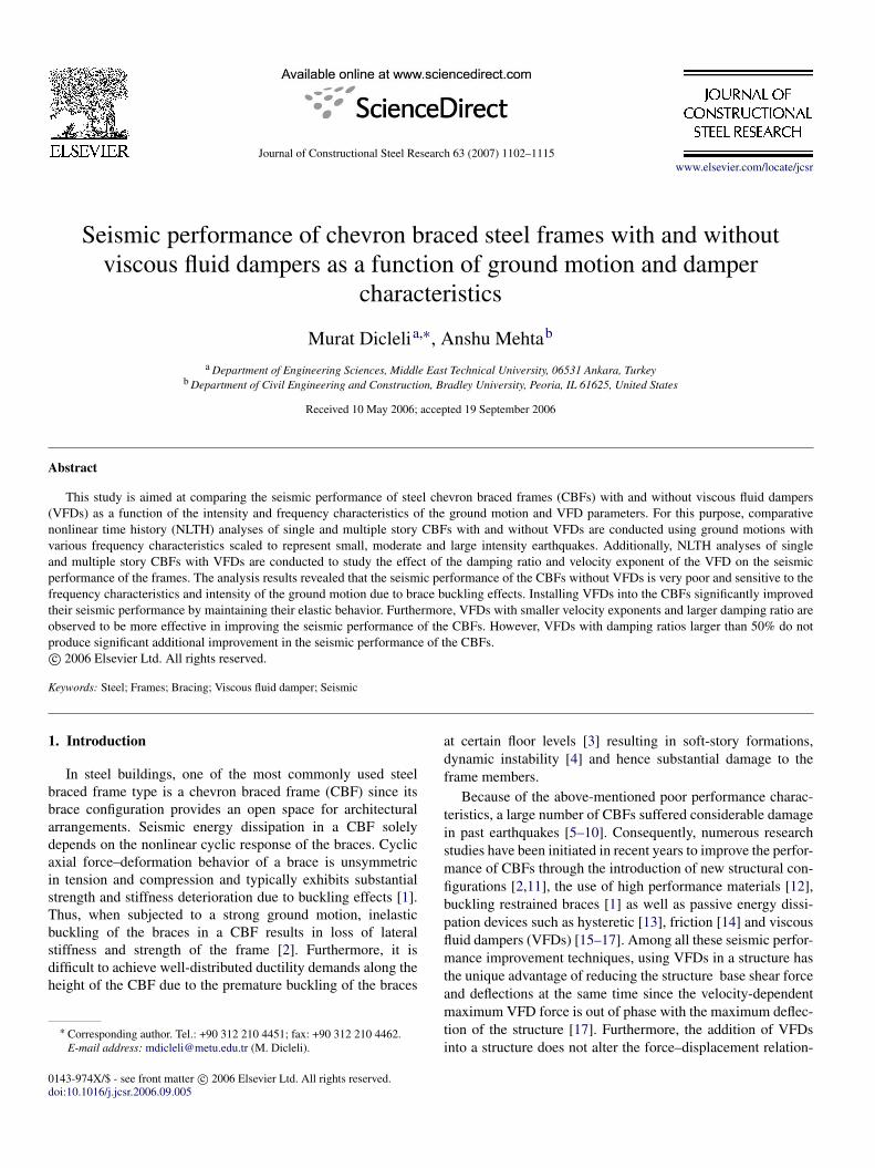
9.2.2. Seismic response of the frames vs. velocity exponentThe average of the maximum inter-story drifts of the one
and four-story CBFs from the seven earthquakes is plotted inFig. 10(a) as a function of the velocity exponent, α, for Ap =
0.35 and 0.50g. It is observed that the relationship betweenthe maximum inter-story drift and the velocity exponent isnearly linear and similar regardless of the value of the peakground acceleration. The maximum inter-story drift increasesas the velocity exponent increases. This trend results from thevalues of damper velocities which are smaller than 1.0 m/sfor the range of Ap/Vp ratios and ground motion intensitiesconsidered in this study. From Eq. (1) and Fig. 10(b), itis clearly observed that for damper velocities smaller than1.0 m/s, VFDs with larger α values produce smaller damperresistance, which in turn, leads to larger inter-story drifts.Furthermore, Fig. 10(a) reveals that for the four-story frame, therate of change of the maximum inter-story drift as a functionof the velocity exponent is lower than that of the one-storyframe. This is again mainly due to the smaller relative dampervelocities at higher stories of the four-story frame producingless damping effect compared to that of the single story frame.
10. Practical implications of using VFDs
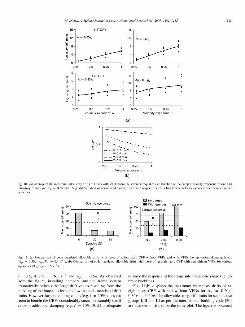
In this section, the practical implications of using VFDs forseismic retrofitting and design of CBFs are studied. Fig. 11(a)shows the maximum inter-story drifts of a four-story CBFwithout VFDs (zero damping) and with VFDs producing 30%and 50% damping ratio in the first vibration mode. Theallowable story drift limits for building seismic use groupsI, II and III as per the international building code [30] arealso demonstrated on the same plot. The figure is obtained for
M. Dicleli, A. Mehta / Journal of Constructional Steel Research 63 (2007) 1102–1115 1113
Fig. 10. (a) Average of the maximum inter-story drifts of CBFs with VFDs from the seven earthquakes as a function of the damper velocity exponent for one andfour-story frames and A p = 0.35 and 0.50g. (b) Variation of normalized damper force with respect to C as a function of velocity exponent for various dampervelocities.
Fig. 11. (a) Comparison of code mandated allowable drifts with those of a four-story CBF without VFDs and with VFDs having various damping levels(A p = 0.50g, A p/Vp = 6.1 s−1). (b) Comparison of code mandated allowable drifts with those of an eight-story CBF with and without VFDs for variousA p values (A p/Vp = 5.5 s−1).
α = 0.5, Ap/Vp = 6.1 s−1 and Ap = 0.5g. As observedfrom the figure, installing dampers into the frame systemdramatically reduces the large drift values resulting from thebuckling of the braces to levels below the code mandated driftlimits. However, larger damping values (e.g. ζ = 50%) does notseem to benefit the CBFs considerably since a reasonably smallvalue of additional damping (e.g. ζ = 10%–30%) is adequate
to force the response of the frame into the elastic range (i.e. nobrace buckling).
Fig. 11(b) displays the maximum inter-story drifts of aneight-story CBF with and without VFDs for Ap = 0.20g,0.35g and 0.50g. The allowable story drift limits for seismic usegroups I, II and III as per the international building code [30]are also demonstrated on the same plot. The figure is obtained

1114 M. Dicleli, A. Mehta / Journal of Constructional Steel Research 63 (2007) 1102–1115
for ζ = 50%, α = 0.5, Ap/Vp = 5.5 s−1. It is observed fromthe figure that installing VFDs into the frame system reducesthe large drift values resulting from the buckling of the bracesto levels below the code mandated drift limits for the range ofAp values considered. As observed earlier, installing dampersbecomes more beneficial for higher ground motion intensitiesand frames with larger number of stories where brace bucklingdominates the behavior of the CBF (Fig. 11(a) and (b)).
In summary, using VFDs with ζ = 10%–30% for seismicretrofitting or design of CBFs seems to dramatically improvethe response of the frames and produce drift values smaller thanthose allowed by the building design codes.
11. Conclusions
The effect of VFDs on the seismic performance of CBFsas a function of the intensity and frequency characteristics ofthe ground motion and VFD parameters is investigated. It isobserved that CBFs without VFDs generally display a goodresponse over the range of Ap/Vp ratios considered for lowto moderate intensity earthquakes and for lower number ofstories. Nonetheless, for high intensity earthquakes and forlarger number of stories, a sudden deterioration in the lateralstrength and stiffness and an ensuing increase in the maximumdrift response of the frames are observed due to the effect ofbrace buckling and the behavior of the CBF becomes highlysensitive to the Ap/Vp ratio. Nevertheless, for the CBFs withVFDs, the dampers prevent the buckling of the braces andcause the frame members to remain within their elastic limits.Thus, the frames exhibit smaller inter-story drifts than thecode mandated allowable limits as well as a more uniformlateral displacement profile and distribution of energy demandcompared to the CBFs without VFDs. Additionally, for CBFswith VFDs, the seismic response of the frames is found to besignificantly less sensitive to the Ap/Vp ratio of the groundmotion and the number of stories for the damper parametersconsidered. Thus, using VFDs forms an effective design andretrofit strategy for CBFs.
The parametric studies concerning the effect of dampingratio and the velocity exponent on the seismic response of theCBFs with VFDs revealed that the relationship between themaximum inter-story drift and the damping ratio is nonlinearand similar regardless of the value of the Ap. As expected,the maximum inter-story drift decreases as the damping ratioincreases. However, the reduction in the maximum inter-storydrift is more significant for damping ratios ranging between10% and 30%. Furthermore it is found that it may be moreefficient to place dampers with relatively larger dampingcapacity at the lower stories of multiple-story CBFs. It is alsoobserved that the maximum inter-story drift linearly increasesas the velocity exponent increases. Additionally, using VFDswith smaller α values is found to reduce the sensitivity of theCBFs to the frequency characteristics of the ground motionand hence the performance of the structure becomes morereliable. In summary, it is recommended that using VFDswith small α values and producing damping ratios within therange of 10%–30% is very effective for the seismic design and
retrofitting of CBFs with large number of stories subjected tohigh intensity ground motions.
References
[1] Sabelli R, Mahin S, Chang C. Seismic demands on steel braced framebuildings with buckling-restrained braces. Engineering Structures 2003;25(5):655–66.
[2] Khatib IF, Mahin SA, Pister KS. Seismic behavior of concentricallybraced steel frames. Report no. UCB/EERC-88/01. Earthquake Engineer-ing Research Centre; 1988.
[3] Perotti F, Scarlassara GP. Concentrically braced frames under seismicactions: Nonlinear behavior and design coefficients. EarthquakeEngineering and Structural Dynamics 1991;20(5):409–27.
[4] Tremblay R, Robert N. Seismic performance of low- and medium-risechevron braced steel frames. Canadian Journal of Civil Engineering 2001;28(4):699–714.
[5] Osteraas J, Krawinkler H. The Mexico earthquake of September 19, 1985:Behavior of steel buildings. Earthquake Spectra 1989;5(1):51–88.
[6] Kim H, Goel S. Seismic evaluation and upgrading of braced framestructures for potential local failures. UMCEE 92-24, Ann Arbor: Dept.of Civil and Environmental Engineering, Univ. of Michigan; 1992. p. 290.
[7] Hisatoku TR. Analysis and repair of a high-rise steel building damagedby the 1995 Hyogoken-Nanbu earthquake. In: Proceedings, 64th annualconvention. Sacramento: Structural Engineers Association of California;1995. p. 21–40.
[8] Tremblay R, Timler P, Bruneau M, Filiatrault A. Performance of steelstructures during the 1994 Northridge earthquake. Canadian Journal ofCivil Engineering 1995;22(2):338–60.
[9] Tremblay R, Bruneau M, Nakashima M, Prion HGL, Filiatrault A,DeVall R. Seismic design of steel buildings: Lessons from the 1995Hyogo-ken Nanbu earthquake. Canadian Journal of Civil Engineering1996;23(3):727–56.
[10] Krawinkler H, Anderson CJ, Bertero VV, Holmes W, Theil C. Northridgeearthquake of January 17, 1994: Reconnaissance report, vol. 2 — steelbuildings. Earthquake Spectra 1996; 12 (S1): p. 25–47.
[11] Dicleli M, Mehta A. Seismic response of a single storey innovativesteel frame system. In: Earthquake resistant engineering structures V(Proceedings of the fifth international conference on earthquake resistantengineering structures). Transactions of the Wessex Institute. 2005.p. 259–67.
[12] Wilson JC, Wesolowsky MJ. Shape memory alloys for seismic responsemodification: A state-of-the-art review. Earthquake Spectra 2005;21(2):569–601.
[13] Kamura H, Katayama T, Shimokawa H, Okamoto H. Energy dissipationcharacteristics of hysteretic dampers with low yield strength steel. In:Proceedings, US–Japan joint meeting for advanced steel structures,Tokyo: Building Research Institute; 2000.
[14] Pall AS, Marsh C. Response of friction damped braced frames. ASCEJournal of Structural Division 1982;108(ST6):1313–23.
[15] Constantinou MC, Symans MD. Experimental and analytical investigationof seismic response of structures with supplemental fluid viscousdampers. Technical report, NCEER-92-0032. Buffalo (NY): NationalCenter for Earthquake Engineering Research, State University of NewYork; 1992.
[16] Constantinou MC, Symans MD. Experimental study of seismic responseof buildings with supplemental fluid dampers. Structural Design of TallBuildings 1993;2(2):93–132.
[17] Constantinou MC, Symans MD, Taylor DP. Fluid viscous damper forimproving the earthquake resistance of buildings. In: Proceedings of thesymposium on structural engineering in natural hazards mitigation. Irvine(CA): American Society of Civil Engineers; 1993. p. 718–23.
[18] Martinez-Rodrigo M, Romero ML. An optimum retrofit strategy formoment resisting frames with nonlinear viscous dampers for seismicapplications. Engineering Structures 2003;25(7):913–25.
[19] Tsai CS, Ho C-L, Chang C-W, Chen K-C. Experimental investigationon steel structures equipped with fluid viscous damper. In: ASMEpressure vessels and piping conference. American Society of MechanicalEngineers, Pressure Vessels and Piping Division, Seismic Engineering2001;428(2): 95–101.

M. Dicleli, A. Mehta / Journal of Constructional Steel Research 63 (2007) 1102–1115 1115
[20] Uriz P, Whittaker AS. Retrofit of pre-Northridge steel moment-resistingframes using fluid viscous dampers. Structural Design of Tall Buildings2001;10(5):371–90.
[21] ADINA. Automatic dynamic incremental nonlinear analysis, Version 8.2.Watertown (MA): ADINA R&D, Inc.; 2004.
[22] AISC. Manual of steel construction: Load and resistance factor design.Chicago (IL): American Institute of Steel Construction; 2001.
[23] Dicleli M, Buddaram S. Effect of isolator and ground motion characteris-tics on the performance of seismic-isolated bridges. Earthquake Engineer-ing and Structural Dynamics 2005;35(2):233–50.
[24] Soong TT, Spencer Jr BF. Supplemental energy dissipation: State-of-the-art and state-of-the-practice. Engineering Structures 2002;24(3):243–259.
[25] BSSC. NEHRP recommended provisions for the development of seismic
regulations for new buildings and other structures. Washington (DC):Federal Emergency Management Agency; 1997.
[26] Tedesco JW, McDougal WG, Ross CA. Structural dynamics theory andapplications. Wesley: CA: Addison; 1999.
[27] Bruneau M, Uang CM, Whittaker A. Ductile design of steel structures.New York (NY): McGraw-Hill; 1998.
[28] Dicleli M, Mehta A. Simulation of inelastic cyclic buckling behaviorof steel box sections using ADINA. Computers and Structures [underreview].
[29] Black GR, Wenger BA, Popov EP. Inelastic buckling of steel strutsunder cyclic load reversals. Report no. UCB/EERC-80/40. EarthquakeEngineering Research Centre; 1980.
[30] ICC. International building code. Falls Church (VA): International CodeCouncil; 2000.