journal of constructional steel research -...
TRANSCRIPT
Journal of Constructional Steel Research 98 (2014) 178–187
Contents lists available at ScienceDirect
Journal of Constructional Steel Research
Hybrid damping systems in offshore jacket platforms withfloat-over deck
Ali Jafarabad a,⁎, Majid Kashani b, Mohammad Reza Adl Parvar a, Ali Akbar Golafshani b
a Civil Engineering Department, University of Qom, Qom, P.O. Box 3716146611, Iranb Civil Engineering Department, Sharif University of Technology, Tehran, P.O. Box 11155-9313, Iran
⁎ Corresponding author. Tel.: +98 912 2716259.E-mail addresses: [email protected], m_bank_
http://dx.doi.org/10.1016/j.jcsr.2014.02.0040143-974X/© 2014 Elsevier Ltd. All rights reserved.
a b s t r a c t
a r t i c l e i n f oArticle history:Received 26 July 2012Accepted 12 February 2014Available online 22 April 2014
Keywords:Offshore jacket platformWave-induced fatigue damageSeismic loadFriction damperTuned mass damperHybrid damping system
Employing dampers to control wave-induced and seismic vibrations of offshore jacket platforms is an attractivemethod in order to mitigate fatigue and seismic damage. However, adjustable parameters of a damper are de-signed by considering only one type of environmental loads; either normal-condition load or extreme-condition load. So, it is important to investigate effectiveness of damping system, for both of twomain categoriesof environmental loads. Also it is ideal for the system to have an acceptable performance in both normal and ex-treme conditions. The idea investigated in the current study is to use a friction damper device (FDD) and a tunedmass damper (TMD) simultaneously in offshore jacket platforms with float-over deck to control both fatiguedamage as well as seismic vibration. To develop the idea, adjustable parameters of FDD and TMD have been ad-justed for wave loading. Afterward, they are combined with those designed for earthquake, so the hybriddamping system (HDS) is introduced. By introducing HDS, it is intended to make damping system have a highseismic performance while being effective in fatigue damage mitigation. Moreover, HDS can have different com-binations. So, certain variants of HDS are determined which have much higher performance than the othervariants.
© 2014 Elsevier Ltd. All rights reserved.
1. Introduction
Periodical inspections have demonstrated that offshore platforms inthe Persian Gulf are highly vulnerable to fatigue damage during theiroperational life. Such investigations provide evidence that tubularmembers can experience significant damage including loss of cross sec-tional area, indicating that the fatigue damage should be consideredmore seriously in order to extend the operational life of offshore plat-forms. Nowadays, one third of the existing offshore platforms requirelife extension [1] and life extension process requires structural rehabil-itation. Many researchers have put their focus on various methods forrehabilitating damaged or extra-loaded platforms and fatigue damagemitigation of offshore structures. Conventional rehabilitation methodscan impose excessive cost of underwater welding and fabrication in-cluded in those processes, so a novel technology is proposed by re-searchers. This technology is to equip existing or even new offshoreplatforms with vibration control devices. Vibration control of offshorejacket platforms is very attractive because in general, reduction of thedynamic stress amplitude of an offshore structure by 15% can extendthe service life over two times, and can result in decreasing the expen-diture on the maintenance and inspection of the structure [2].
[email protected] (A. Jafarabad).
On the other hand, offshore platforms are of the economic life linesof oil-rich countries, so it is a serious problem on how to guaranteetheir immediate occupancy after earthquakes. Again, one proposedmethod to solve the problem is to employ vibration control devices.Some researchers have worked on this topic and have found it effectiveto use those devices to control seismic vibrations.
Among those who have studied vibration control of offshore plat-forms are Vincenzo and Roger [3], Ou et al. [4], Li et al. [5], Wang [6],Mahadik and Jangid [7], Zhou and Zhao [8], Patil and Jangid [9], Leeet al. [10], Ou et al. [2], Jin et al. [11], Ma et al. [12], Xu et al. [13], Yueet al. [14], Taflanidis et al. [15] and Kim [16]. All of them have found iteffective to use control mechanisms formitigation of vibrations inducedby different environmental loads.
Recently, in some studies [17,18] adjustable parameters of one typeof FDD have been optimized for realistic jacket platforms for wave-induced hydrodynamic loads. Moreover, Gholizad [19] has optimizedTMD for use against wave-induced fatigue damage. Those works playa key role in the current study, since they are among several sourcesapproached in order to obtain comprehensive data on the subject.
Offshore jacket platforms, located at severe environmental condi-tions, are generally subjected to two main categories of environmentalloading, i.e. normal-condition loads such as wave-induced hydrody-namic force and extreme-condition loads like seismic excitation. Theformer external force has a significant contribution to fatigue damagewhich causes the excessive cost of rehabilitation and the latter one
179A. Jafarabad et al. / Journal of Constructional Steel Research 98 (2014) 178–187
can endanger the serviceability of offshore jacket platformswhich are ofthe economic life lines of oil-rich countries.
Employing novel devices to control the wave-induced and seismicvibrations is an attractive method in order to mitigate fatigue damageand to guarantee immediate occupancy of offshore platforms afterearthquakes. But, adjustable parameters of a vibration control systemfor offshore platforms are generally designed by considering only onetype of environmental loading; either normal-condition load orextreme-condition load. So, it is important to investigate the effective-ness of vibration control system, for both of the two main categoriesof environmental loads.
The overall objective of this study is to investigate the idea of com-bining dampers with different designs to control both of two main cat-egories of environmental loads exerted upon offshore platforms whichare classified into normal-condition loads and extreme-conditionloads. It is to be determined which combination of dampers is themost effective. So far, some other aspects of the idea of employingHDS in offshore jacket platforms have been discussed elsewhere insome papers [20,21].
2. Class of offshore platform under study
The jacket, the piles, and the deck are the main structural compo-nents of the offshore jacket platform. For topside installation, all deck fa-cilities are fabricated into modules and then transported by barge andset on the platform by a derrick. Float-over decks are a developmentwhich enables the prefabrication of the complete topsides, so that itmay be transported by barge and set as a complete unit on thepreinstalled jacket [22]. Withmaking use of float-over decks, some lim-itations are imposed over the characteristics of the platform. Float-overdeck requires omission of bracings in one direction at the water surfacelevel, in order to allow the barge tomove between legs of the jacket andinstall the deck, so the stiffness of the platform at this level is very lowcompared to other levels.
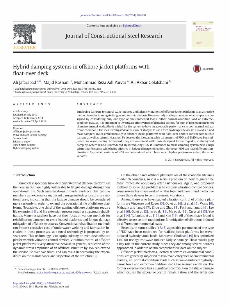
Fig. 1. Case study p
Limitations of high flexibility of the upper elevation in one directioncan be counteracted by making use of auxiliary vibration controldevices.
In the current study, two realistic float-over-deck offshore jacketplatforms shown in Fig. 1 are examined; “North Rankin B” (NRB) is aplatform installed onWestern Australia offshore oil fields with a heightof 125 m and “Foroozan” (FRZ) is a six leg platform located in waters ofthe Persian Gulf with a height of 95 m. As their topsides have beeninstalled with float-over technique, the bracings have been omitted inone direction at the water surface level. As a consequence, making useof auxiliary vibration control devices is a novel suggestion to counteractthe effects of high flexibility at the upper levels of the jacket.
An idealized three-degree-of-freedom (3DOF) system (Fig. 2) is con-sidered as the structural model for each platform. The values of lumpedmass and pre-yielding stiffness have been determined by Golafshaniand Gholizad [17] in a way that the overall model would have thesame natural period and kinetic energy for each mode of vibration asthe real overall platform. Some detailed descriptions of structuralmodels, such as pre-yielding stiffness and lumped mass values, arelisted in Table 1. In this table them1, m2 andm3 parameters are respec-tively the lumpedmass of the first, second and third stories of the ideal-ized 3DOF model of the platforms and the k1, k2 and k3 parameters arerespectively the stiffness of the first, second and third stories of themodel. For each platform a proportional damping matrix is determinedby considering the damping ratio for the first three modes of vibrationto be 0.05, 0.03 and 0.02 [17].
3. Damping systems
3.1. FDD
FDD is a novel friction damper which can havemany variousmodelsand configurations. It has been innovated byMualla [23,24]. One simpleconfiguration of FDD is shown in Fig. 3 This new damper device is basedon friction between pad disks and steel plates. Simplicity of concept and
latforms [17].
+13.5
-8.5
-34
-72.5
+16
-19.5
-54
-102
Story levels of FRZ Platform’s
model
Story levels of NRB Platform’s
model
Fig. 2.Modeling of the platforms by idealized three-degree-of-freedom (3DOF) system.
180 A. Jafarabad et al. / Journal of Constructional Steel Research 98 (2014) 178–187
design allows this device to be constructed for projects with space lim-itation and high force level.
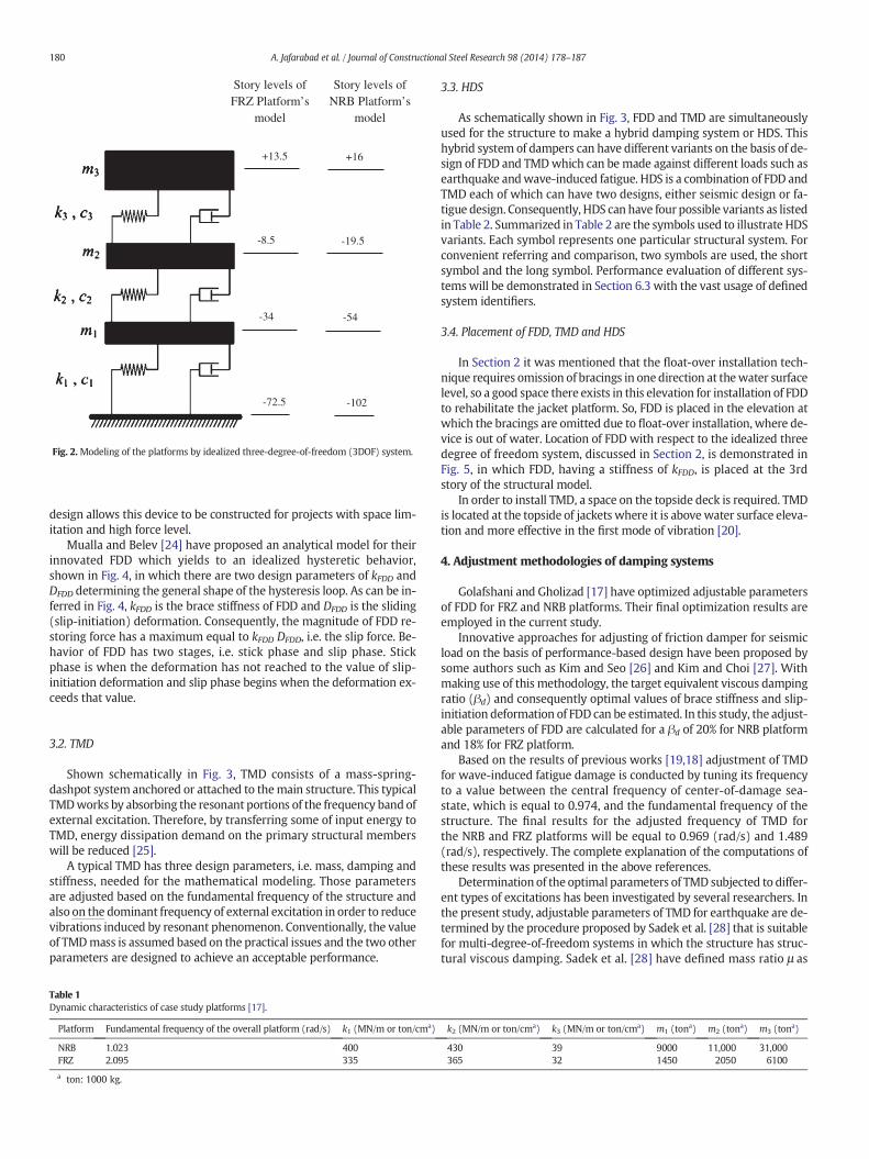
Mualla and Belev [24] have proposed an analytical model for theirinnovated FDD which yields to an idealized hysteretic behavior,shown in Fig. 4, in which there are two design parameters of kFDD andDFDD determining the general shape of the hysteresis loop. As can be in-ferred in Fig. 4, kFDD is the brace stiffness of FDD and DFDD is the sliding(slip-initiation) deformation. Consequently, the magnitude of FDD re-storing force has a maximum equal to kFDD DFDD, i.e. the slip force. Be-havior of FDD has two stages, i.e. stick phase and slip phase. Stickphase is when the deformation has not reached to the value of slip-initiation deformation and slip phase begins when the deformation ex-ceeds that value.
3.2. TMD
Shown schematically in Fig. 3, TMD consists of a mass-spring-dashpot system anchored or attached to themain structure. This typicalTMDworks by absorbing the resonant portions of the frequency band ofexternal excitation. Therefore, by transferring some of input energy toTMD, energy dissipation demand on the primary structural memberswill be reduced [25].
A typical TMD has three design parameters, i.e. mass, damping andstiffness, needed for the mathematical modeling. Those parametersare adjusted based on the fundamental frequency of the structure andalso on the dominant frequency of external excitation in order to reducevibrations induced by resonant phenomenon. Conventionally, the valueof TMDmass is assumed based on the practical issues and the two otherparameters are designed to achieve an acceptable performance.
Table 1Dynamic characteristics of case study platforms [17].
Platform Fundamental frequency of the overall platform (rad/s) k1 (MN/m or ton/cma)
NRB 1.023 400FRZ 2.095 335
a ton: 1000 kg.
3.3. HDS
As schematically shown in Fig. 3, FDD and TMD are simultaneouslyused for the structure to make a hybrid damping system or HDS. Thishybrid system of dampers can have different variants on the basis of de-sign of FDD and TMDwhich can be made against different loads such asearthquake andwave-induced fatigue. HDS is a combination of FDD andTMD each of which can have two designs, either seismic design or fa-tigue design. Consequently, HDS can have four possible variants as listedin Table 2. Summarized in Table 2 are the symbols used to illustrate HDSvariants. Each symbol represents one particular structural system. Forconvenient referring and comparison, two symbols are used, the shortsymbol and the long symbol. Performance evaluation of different sys-temswill be demonstrated in Section 6.3 with the vast usage of definedsystem identifiers.
3.4. Placement of FDD, TMD and HDS
In Section 2 it was mentioned that the float-over installation tech-nique requires omission of bracings in one direction at thewater surfacelevel, so a good space there exists in this elevation for installation of FDDto rehabilitate the jacket platform. So, FDD is placed in the elevation atwhich the bracings are omitted due to float-over installation, where de-vice is out of water. Location of FDD with respect to the idealized threedegree of freedom system, discussed in Section 2, is demonstrated inFig. 5, in which FDD, having a stiffness of kFDD, is placed at the 3rdstory of the structural model.
In order to install TMD, a space on the topside deck is required. TMDis located at the topside of jackets where it is abovewater surface eleva-tion and more effective in the first mode of vibration [20].
4. Adjustment methodologies of damping systems
Golafshani and Gholizad [17] have optimized adjustable parametersof FDD for FRZ and NRB platforms. Their final optimization results areemployed in the current study.
Innovative approaches for adjusting of friction damper for seismicload on the basis of performance-based design have been proposed bysome authors such as Kim and Seo [26] and Kim and Choi [27]. Withmaking use of this methodology, the target equivalent viscous dampingratio (βd) and consequently optimal values of brace stiffness and slip-initiation deformation of FDD can be estimated. In this study, the adjust-able parameters of FDD are calculated for a βd of 20% for NRB platformand 18% for FRZ platform.
Based on the results of previous works [19,18] adjustment of TMDfor wave-induced fatigue damage is conducted by tuning its frequencyto a value between the central frequency of center-of-damage sea-state, which is equal to 0.974, and the fundamental frequency of thestructure. The final results for the adjusted frequency of TMD forthe NRB and FRZ platforms will be equal to 0.969 (rad/s) and 1.489(rad/s), respectively. The complete explanation of the computations ofthese results was presented in the above references.
Determination of the optimal parameters of TMD subjected to differ-ent types of excitations has been investigated by several researchers. Inthe present study, adjustable parameters of TMD for earthquake are de-termined by the procedure proposed by Sadek et al. [28] that is suitablefor multi-degree-of-freedom systems in which the structure has struc-tural viscous damping. Sadek et al. [28] have defined mass ratio μ as
k2 (MN/m or ton/cma) k3 (MN/m or ton/cma) m1 (tona) m2 (tona) m3 (tona)
430 39 9000 11,000 31,000365 32 1450 2050 6100
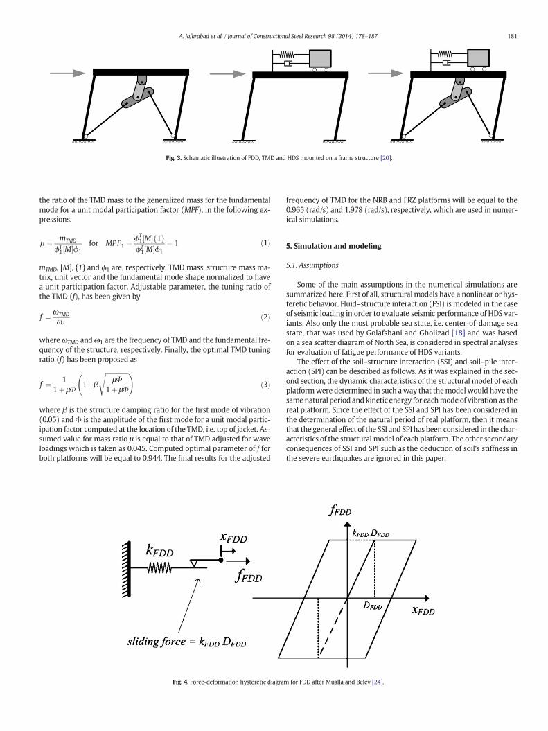
Fig. 3. Schematic illustration of FDD, TMD and HDS mounted on a frame structure [20].
181A. Jafarabad et al. / Journal of Constructional Steel Research 98 (2014) 178–187
the ratio of the TMD mass to the generalized mass for the fundamentalmode for a unit modal participation factor (MPF), in the following ex-pressions.
μ ¼ mTMD
ϕT1 M½ �ϕ1
for MPF1 ¼ ϕT1 M½ � 1f gϕT1 M½ �ϕ1
¼ 1 ð1Þ
mTMD, [M], {1} and ϕ1 are, respectively, TMD mass, structure mass ma-trix, unit vector and the fundamental mode shape normalized to havea unit participation factor. Adjustable parameter, the tuning ratio ofthe TMD (f), has been given by
f ¼ ωTMD
ω1ð2Þ
whereωTMD andω1 are the frequency of TMD and the fundamental fre-quency of the structure, respectively. Finally, the optimal TMD tuningratio (f) has been proposed as
f ¼ 11þ μΦ
1−β
ffiffiffiffiffiffiffiffiffiffiffiffiffiffiffiμΦ
1þ μΦ
s !ð3Þ
where β is the structure damping ratio for the first mode of vibration(0.05) andΦ is the amplitude of the first mode for a unit modal partic-ipation factor computed at the location of the TMD, i.e. top of jacket. As-sumed value for mass ratio μ is equal to that of TMD adjusted for waveloadings which is taken as 0.045. Computed optimal parameter of f forboth platforms will be equal to 0.944. The final results for the adjusted
Fig. 4. Force-deformation hysteretic diagram
frequency of TMD for the NRB and FRZ platforms will be equal to the0.965 (rad/s) and 1.978 (rad/s), respectively, which are used in numer-ical simulations.
5. Simulation and modeling
5.1. Assumptions
Some of the main assumptions in the numerical simulations aresummarized here. First of all, structuralmodels have a nonlinear or hys-teretic behavior. Fluid–structure interaction (FSI) is modeled in the caseof seismic loading in order to evaluate seismic performance of HDS var-iants. Also only the most probable sea state, i.e. center-of-damage seastate, that was used by Golafshani and Gholizad [18] and was basedon a sea scatter diagram of North Sea, is considered in spectral analysesfor evaluation of fatigue performance of HDS variants.
The effect of the soil–structure interaction (SSI) and soil–pile inter-action (SPI) can be described as follows. As it was explained in the sec-ond section, the dynamic characteristics of the structural model of eachplatformwere determined in such away that themodelwould have thesamenatural period and kinetic energy for eachmodeof vibration as thereal platform. Since the effect of the SSI and SPI has been considered inthe determination of the natural period of real platform, then it meansthat the general effect of the SSI and SPI has been considered in the char-acteristics of the structural model of each platform. The other secondaryconsequences of SSI and SPI such as the deduction of soil's stiffness inthe severe earthquakes are ignored in this paper.
for FDD after Mualla and Belev [24].
Table 2HDS variants.
Short symbol Long symbol Description
HDS1 FDD for fatigue + TMD for fatigue Structure equipped with HDS in which FDD is adjusted for fatigue and TMD is adjusted for fatigueHDS2 FDD for quake + TMD for quake Structure equipped with HDS in which FDD is adjusted for quake and TMD is adjusted for quakeHDS3 FDD for fatigue + TMD for quake Structure equipped with HDS in which FDD is adjusted for fatigue and TMD is adjusted for quakeHDS4 FDD for quake + TMD for fatigue Structure equipped with HDS in which FDD is adjusted for quake and TMD is adjusted for fatigue
182 A. Jafarabad et al. / Journal of Constructional Steel Research 98 (2014) 178–187
5.2. Mathematical modeling
The equations of dynamic motion for an offshore platform idealizedas 3DOF systemwith hysteretic behavior equipped with HDS in the 3rdstory and subjected to external load of wave or earthquake can be writ-ten by coupled equations as shown below.
M½ � xf g þ C½ � x��þ f sf g þ0
− f FDDf FDD
8<:
9=;þ
00
cTMDzþ kTMDz
8<:
9=;
¼ f externalf g ð4Þ
mTMDzþ cTMDzþ kTMDz ¼ −mTMDxtop total ð5Þ
f externalf g ¼ f Morisonf g if wave− M½ � 1f gxg þ f FSIf g if quake
�ð6Þ
Equations of structure and TMDmust be simultaneously solved be-cause they are coupled with each other. {x}, [M], [C], {fs}, fFDD, {fexternal},{fMorison}, {1}, xg , {fFSI}, mTMD, cTMD, kTMD, z and xtop total are, respectively,the displacement vector, mass matrix, proportional damping matrix,stiffness restoring force vector, control force vector due to FDD, externalload vector due to earthquake or wave, Morisonwave load vector (referto Section 5.3), unit vector, ground acceleration, force vector due to FSI,TMDmass, TMD damping, TMD stiffness, displacement of TMD relativeto the top of jacket and total acceleration at the top of jacket.
Since the structure is assumed to have a nonlinear or hysteretic be-havior, the stiffness force vector {fs} can bewritten byhysteresismodels.Also, the force vector due to FDD {fFDD} can be simulated by hysteresis
Fig. 5. Location of FDD in the idealized 3DOF system after Golafshani and Gholizad [17].
models. For modeling of {fs} and fFDD, one notation of the Bouc–Wenmodel [29] used by Yang et al. [30] is adopted. Based on the Bouc–Wen model, the hysteretic force of FDD installed in the 3rd story, canbe expressed as
f FDD ¼ αFDDkFDDxFDD þ 1−αFDDð ÞkFDDDFDDvFDD ð7Þ
in which αFDD is the ratio of post-slip to pre-slip brace stiffness of FDD,xFDD is the drift of the 3rd story, kFDD is brace stiffness of FDD installedin the 3rd story, DFDD is slip-initiation deformation of FDD and vFDD is anon-dimensional variable introduced to describe the hysteresis compo-nent of the deformation, with the limitation of |vFDD | ≤ 1, where
vFDD ¼ D−1FDD AFDDxFDD−βFDD xFDD
�� �� vFDDj jnFDD−1vFDD−γFDDxFDD vFDDj jnFDD� �
ð8Þ
Parameters AFDD,βFDD andγFDD govern the scale and general shape ofthe hysteresis loop and nFDD determines the smoothness of the force-deformation curve. To model a hysteresis loop that is appropriate forthe FDD, parameters of Bouc–Wen model are considered as
αFDD ¼ 0:0; AFDD ¼ 1:0; βFDD ¼ 0:5; γFDD ¼ 0:5; and nFDD ¼ 95 :
ð9Þ
Methodology of simulation of {fs} by the Bouc–Wenmodel is similarto that of fFDD. Parameters of Bouc–Wenmodel for {fs} are considered forall the three stories as
αs ¼ 0:1; As ¼ 1:0; βs ¼ 0:5; γs ¼ 0:5; and ns ¼ 95 ð10Þ
The force vector {fFSI} is written as [31,16]
f FSIf g ¼ ρ km−1ð Þ V½ � uf g− xtotalf gð Þ þ ρ V½ � uf g þ ρkd A½ �� u−xtotal�� �� u−xtotal
� � ð11Þ
xtotal� � ¼ x
��þ 1f gxg ; xtotalf g ¼ xf g þ 1f gxg ð12Þ
Where ρ, km, kd, [V], [A] and {u} are the sea water density, inertia coeffi-cient taken constant in depth as 2.0, drag coefficient taken constant indepth as 0.7, body volumematrix, projected area matrix andwater par-ticle horizontal motion vector, respectively.When the only load consid-ered is due to groundmotion, the water particle motion is neglected. Inthis case, water particle velocity vector and water particle accelerationvector would be equal to zero, and the force vector due to FSI can bewritten in the following form.
f FSIf g ¼ ρ km−1ð Þ V½ � − xtotalf gð Þ þ ρkd A½ � xtotal�� �� −xtotal
� � ð13Þ
It is possible to use addedmass concept and change the formulationof equations or even linearize the drag term, but in our numerical sim-ulations, formulation of FSI force and its nonlinearity is preserved.
5.3. Selected technique for spectral analysis
This study is concerned with the spectral analysis of gravity wavesgenerated by wind action. This type of surface water wave induces fa-tigue damage in offshore jacket platforms. Several approaches are

183A. Jafarabad et al. / Journal of Constructional Steel Research 98 (2014) 178–187
available in API RP2A-WSD [32] for determining structural response tosea-state loadings. Spectral analysis is recommended by API RP2A-WSD [32] to be used to properly account for the actual distribution ofwave energy over the entire frequency range. The spectral approachhas been subdivided by API RP2A-WSD [32] into three main methodol-ogies as shown below, based upon themethod used to develop transferfunction.
1 Transfer functions developed using regular waves in the timedomain.
2 Transfer functions developed using regular waves in the frequencydomain.
3 Transfer functions developed using random waves in the timedomain.
The first of the above-mentioned methodologies is employed in thecurrent study. This methodology does not require any linearization, i.e.the drag term in the wave force expressed by Morison equation can beemployed in its original non-linear form and also hysteretic behavior ofboth structural elements as well as FDD can be simulated. The objectiveis to compute variance of structural response with the aid of a transferfunction from power spectral density function (PSDF) of wave heightto PSDF of structural response. In this process a wave spectrum alongwith a wave theory is employed to create regular progressive waves.When each regular wave passes through the structure, with makinguse of nonlinear form of Morison equation, the force vector exertedupon the structure is determined. Structural analysis is conducted tocompute structural response. Dividing the structural response by thewave height gives a point on the transfer function at the frequency ofthe regular wave. Moreover, the area under the PSDF of structural re-sponse will provide the variance value of response [33]. This character-istic is one important property of PSDF curve.
Characterization of the wave climate is carried out using PSDF ofwave height or wave amplitude. In this study, to express uni-directional random wave loading, Pierson–Moskowitz wave heightspectrum is employed [34,35] which is expressed as
Sζζ ωð Þ ¼ 124:37H2s
T4z
ω−5 exp−497:5
T4z
ω−5� �
ð14Þ
in which Hs and Tz are significant wave height and wave zero up cross-ing period, respectively. Hs and Tz are adopted for the center-of-damagesea-state used by Golafshani and Gholizad [18].
Le Mehaute [36] provided a chart detailing applicability of variouswave theories using wave steepness versus depth parameter in his de-scription. In the current study, with making use of the linear wave the-ory originally developed by Airy [37], water surface profile isdetermined. Water surface elevation profile η can be written in the fol-lowing form where k, ω, λ, T and g are the wave number, the wave fre-quency, the wave length, the wave period and acceleration due togravity, respectively 37,34.
η x; tð Þ ¼ a sin kx−ωtð Þ ð15Þ
k ¼ 2πλ
¼ ω2
g¼ 4π2
gT2 ð16Þ
The amplitude a of the water surface profile for a regular wave canbe determined based on the frequency difference Δω corresponding tothat of a regular wave and the area under the wave spectrum, asexpressed in the following equation [38,39].
a ¼ffiffiffiffiffiffiffiffiffiffiffiffiffiffiffiffiffiffiffiffiffiffiffiffi2Sζζ ωð ÞΔω
qð17Þ
The next step is to compute the velocity and acceleration of waterparticles which are dependent upon the depth of water. The horizontal
component of velocity and acceleration of water particles is expressedin the following mathematical formulas [37].
u x; y; tð Þ ¼ aωcosh k yþ dð Þð Þ
sinh kdð Þ sin kx−ωtð Þ ð18Þ
u x; y; tð Þ ¼ −aω2 cosh k yþ dð Þð Þsinh kdð Þ cos kx−ωtð Þ ð19Þ
Making use of horizontal component of velocity and acceleration ofwater particles, we can employ Morison equation to compute theforce vector exerted upon tubular members of jacket platforms foreach regular wave [40]. So, the force vector becomes [31,16]
f Morisonf g ¼ ρ km−1ð Þ V½ � uf g− xf gð Þ þ ρ V½ � uf g þ ρkd A½ � u−x�� �� u−x
� � ð20Þ
in which u and x are displacements of water particles and structural el-ements, respectively. In this study, the nonlinearity ofMorison equationis taken into account.
After generating the force vector due to regular waves, dynamicanalysis of each offshore platform under each regular wave force vectoris conducted in order to obtain structural response. The analysis proce-dure must eliminate transient effects by achieving steady state condi-tions. So, a sufficient number of time steps in the wave cycle at whichstructural response is computed should be selected to determine themaximum structural response [32]. Dividing the maximum structuralresponse in the steady state condition by the wave height gives apoint on the transfer function at the frequency of the regular wave.After computing the enough number of points on the transfer function,PSDF of the platform response can be obtained as
Srr ωð Þ ¼ Hrς ωð Þ�� ��2Sςς ωð Þ ð21Þ
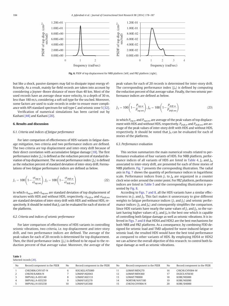
in which Srr, Hrς and Sςς are PSDF of structural response, transfer func-tion and PSDF of wave height, respectively. So, PSDF of structural re-sponse is computed such as those shown in Fig. 6. It should beremembered that the center-of-damage sea state has been assumedfor the computation of the transfer function and for each platform anal-ysis. In the center-of-damage sea state, which is based on a sea scatterdiagram of North Sea, the quantities of significant wave height (Hs)and wave zero up crossing period (Tz) are 1.88 (m) and 4.88 (s) respec-tively. Since the central frequency of wave spectrum and fundamentalfrequency of NRB platform are very close to each other, only one peakthere exists in its PSDF of top displacement. In the PSDF of top displace-ment of the FRZ platform, the first peak is related to the central frequen-cy of wave spectrum and the second one is because of the fundamentalfrequency of FRZ platform.
5.4. Record selection
For designing fixed offshore platforms against the earthquake load,API RP2A-WSD [32] recommends where the time history method isused, the design response should be calculated as the average of thepeak values for each of the time histories considered. Moreover, basedon requirements of FEMA 356 [41], where seven or more time historydata sets are employed, the average value of each response parametershall be permitted to determine design acceptability. Consequently,the number of records in the present two-dimensional study is finallyselected not fewer than seven time histories [20]. So, 20 time historiesare employed for seismic analysis.
Listed in Table 3, a subset of the PEER NGA database [42] and PEERStrongMotion Database [43] is used fromwhich it is tried to exclude re-cordings thatwere believed to be near-field groundmotions. Recent ex-periences show that near-field earthquakes have high peak accelerationandhigh velocity pulse. As they do not behave like far-field earthquakes,
0 1 2 0
1.20E-01
1.00E-01
8.00E-02
6.00E-02
4.00E-02
2.00E-02
0.00E+00
1.20E+01
1.00E+01
8.00E+00
6.00E+00
4.00E+00
2.00E+00
0.00E+00
1 2 3 4
PSD
F of
top
disp
. (cm
2*
sec/
rad)
PSD
F of
top
disp
. (cm
2*
sec/
rad)
frequency (rad/sec) frequency (rad/sec)
Fig. 6. PSDF of top displacement for NRB platform (left) and FRZ platform (right).
184 A. Jafarabad et al. / Journal of Constructional Steel Research 98 (2014) 178–187
but like a shock, passive dampers may fail to dissipate input energy ef-ficiently. As a result, mainly far-field records are taken into account byconsidering a Joyner–Boore distance of more than 40 km. Most of theused records have an average shear wave velocity, to a depth of 30 m,less than 180m/s, considering a soft soil type for the sea bed. Moreover,some factors are used to scale records in order to ensure more compli-ancewith API standard spectrum for soil type C and seismic zone 5 [32].
Verification of numerical simulations has been carried out byKashani [44] and Kashani [20].
6. Results and discussion
6.1. Criteria and indices of fatigue performance
For later comparison of effectiveness of HDS variants in fatigue dam-age mitigation, two criteria and two performance indices are defined.The two criteria are top displacement and inter-story drift because oftheir direct correlation with accumulative fatigue damage [18]. The firstperformance index (J1) is defined as the reduction percent of standard de-viation of top displacement. The second performance index (J2) is definedas the reduction percent of standard deviation of inter-story drift. Formu-lations of two fatigue performance indices are defined as below.
J1 ¼ 100 1−σ top;w
σ top;wo
!; J2 ¼ 100 1−
σdrift;w
σdrift;wo
!ð22Þ
in which σtop,w and σtop,wo are standard deviation of top displacement ofstructures with HDS and without HDS, respectively. σdrift,w and σdrift,wo
are standard deviation of inter-story drift with HDS and without HDS, re-spectively. It should be noted that J2 can be evaluated for each of stories ofthe platforms.
6.2. Criteria and indices of seismic performance
For later comparison of effectiveness of HDS variants in controllingseismic vibrations, two criteria, i.e. top displacement and inter-storydrift, and two performance indices are defined. The average of thepeak values for each of 20 records is determined for top displacement.Then, the third performance index (J3) is defined to be equal to the re-duction percent of that average value. Moreover, the average of the
Table 3Selected records [20].
No Record/component in the PEER No Record/component in the PEER
1 CHICHI06/CHY107-N 6 KOCAELI/ATS0002 CHICHI/ILA004-N 7 LOMAP/A020433 IMPVALL/A-E03140 8 LOMAP/A021334 IMPVALL/A-E03230 9 LOMAP/LKS2705 IMPVALL/H-E03230 10 LOMAP/LKS360
peak values for each of 20 records is determined for inter-story drift.The corresponding performance index (J4) is defined by computingthe reduction percent of that average value. Finally, the two seismic per-formance indices are defined as below.
J3 ¼ 100 1−Ptop;w
Ptop;wo
!; J4 ¼ 100 1−
Pdrift;w
Pdrift;wo
!ð23Þ
in which Ptop,w and Ptop,wo are average of the peak values of top displace-mentwithHDS andwithoutHDS, respectively. Pdrift,w and Pdrift,wo are av-erage of the peak values of inter-story drift with HDS and without HDS,respectively. It should be noted that J4 can be evaluated for each ofstories of the platforms.
6.3. Performance evaluation
This section summarizes the main numerical results related to per-formance evaluation of four variants of HDS. For NRB platform, perfor-mance indices of all variants of HDS are listed in Table 4. J2 and J4,associated to inter-story drift, are presented for each of three stories ofNRB platform. Fig. 7 presents the corresponding illustration. The radialaxis in Fig. 7 shows the quantity of performance indices in logarithmicscale. Performance indices from J1 to J4 are organized in a counterclockwise order around the center point. For FRZplatform, performanceindices are listed in Table 5 and the corresponding illustration is pre-sented by Fig. 8.
According to Figs. 7 and 8, all the HDS variants have a similar effec-tiveness in J1 and J2. This fact makes it unnecessary to give differentweights to fatigue performance indices (J1 and J2) and seismic perfor-mance indices (J3 and J4) and consequently simplifies the comparison.Since HDS variants have nearly the same values of J1 and J2, so the var-iant having higher values of J3 and J4 is the best one which is capableof controlling both fatigue damage as well as seismic vibrations. It is in-ferred in Figs. 7 and 8 that HDS4 and HDS2 are the best mechanisms forboth NRB and FRZ platforms. As a consequence, by combining FDD de-signed for seismic load and TMD adjusted for wave-induced fatigue orseismic load, the resulted HDS would have the best total performanceas compared to other variants of HDS. By employing HDS4 or HDS2we can achieve the overall objective of this research: to control both fa-tigue damage as well as seismic vibrations.
No Record/component in the PEER No Record/component in the PEER
11 LOMAP/MEN270 16 CHICHI/CHY004-W12 LOMAP/MEN360 17 DUZCE/ATS03013 LOMAP/TRI000 18 KOBE/NIS00014 NORTHR/WAT180 19 KOBE/NIS09015 CHICHI/CHY004-N 20 KOBE/SHI000
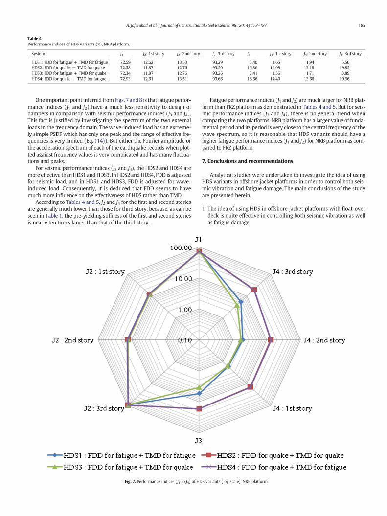
Table 4Performance indices of HDS variants (%), NRB platform.
System J1 J2: 1st story J2: 2nd story J2: 3rd story J3 J4: 1st story J4: 2nd story J4: 3rd story
HDS1: FDD for fatigue + TMD for fatigue 72.59 12.62 13.53 93.29 5.40 1.65 1.94 5.50HDS2: FDD for quake + TMD for quake 72.58 11.87 12.76 93.50 16.86 14.09 13.18 19.95HDS3: FDD for fatigue + TMD for quake 72.34 11.87 12.76 93.26 3.41 1.56 1.71 3.89HDS4: FDD for quake + TMD for fatigue 72.93 12.61 13.51 93.66 16.66 14.40 13.66 19.96
185A. Jafarabad et al. / Journal of Constructional Steel Research 98 (2014) 178–187
One important point inferred fromFigs. 7 and 8 is that fatigue perfor-mance indices (J1 and J2) have a much less sensitivity to design ofdampers in comparison with seismic performance indices (J3 and J4).This fact is justified by investigating the spectrum of the two externalloads in the frequency domain. Thewave-induced load has an extreme-ly simple PSDF which has only one peak and the range of effective fre-quencies is very limited (Eq. (14)). But either the Fourier amplitude orthe acceleration spectrum of each of the earthquake records when plot-ted against frequency values is very complicated and has many fluctua-tions and peaks.
For seismic performance indices (J3 and J4), the HDS2 and HDS4 aremore effective thanHDS1 andHDS3. InHDS2 andHDS4, FDD is adjustedfor seismic load, and in HDS1 and HDS3, FDD is adjusted for wave-induced load. Consequently, it is deduced that FDD seems to havemuch more influence on the effectiveness of HDS rather than TMD.
According to Tables 4 and 5, J2 and J4 for the first and second storiesare generally much lower than those for third story, because, as can beseen in Table 1, the pre-yielding stiffness of the first and second storiesis nearly ten times larger than that of the third story.
Fig. 7. Performance indices (J1 to J4) of HD
Fatigue performance indices (J1 and J2) aremuch larger for NRB plat-form than FRZ platform as demonstrated in Tables 4 and 5. But for seis-mic performance indices (J3 and J4), there is no general trend whencomparing the two platforms. NRB platform has a larger value of funda-mental period and its period is very close to the central frequency of thewave spectrum, so it is reasonable that HDS variants should have ahigher fatigue performance indices (J1 and J2) for NRB platform as com-pared to FRZ platform.
7. Conclusions and recommendations
Analytical studies were undertaken to investigate the idea of usingHDS variants in offshore jacket platforms in order to control both seis-mic vibration and fatigue damage. The main conclusions of the studyare presented herein.
1 The idea of using HDS in offshore jacket platforms with float-overdeck is quite effective in controlling both seismic vibration as wellas fatigue damage.
S variants (log scale), NRB platform.
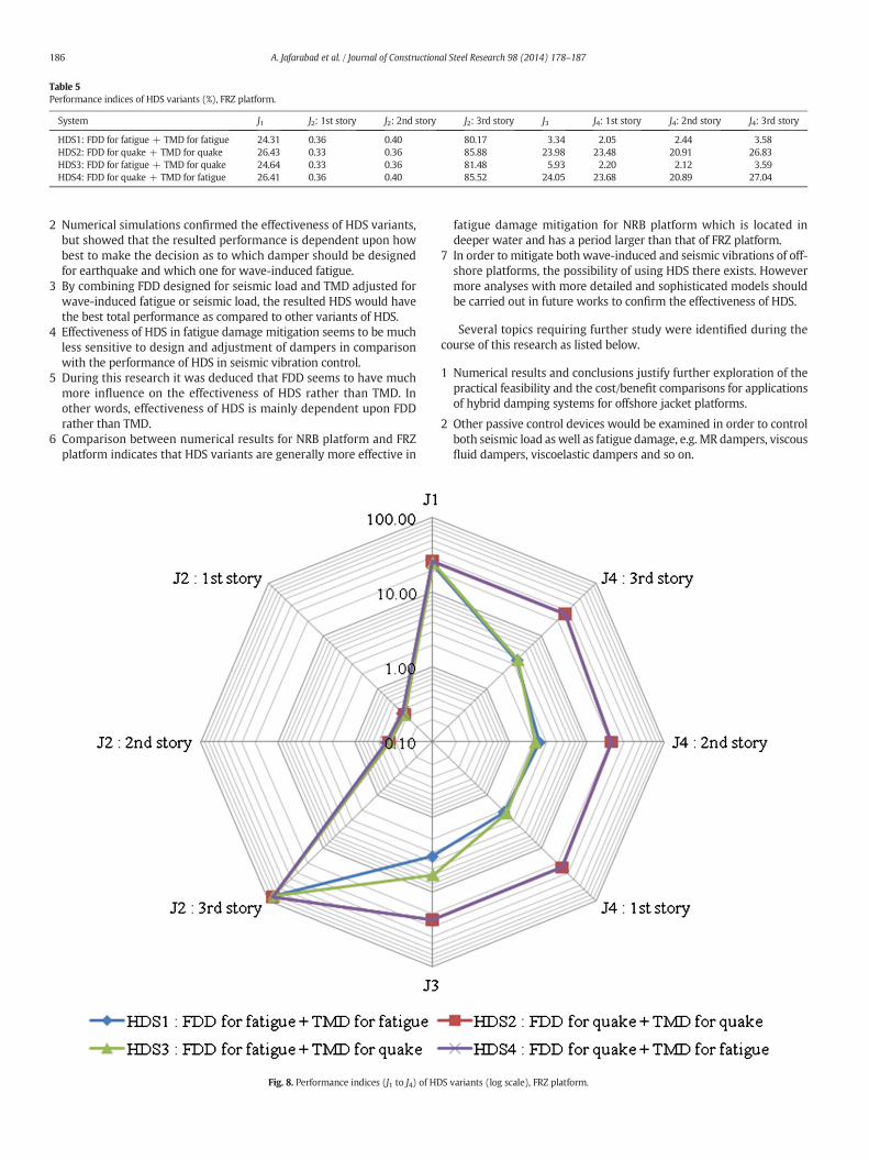
Table 5Performance indices of HDS variants (%), FRZ platform.
System J1 J2: 1st story J2: 2nd story J2: 3rd story J3 J4: 1st story J4: 2nd story J4: 3rd story
HDS1: FDD for fatigue + TMD for fatigue 24.31 0.36 0.40 80.17 3.34 2.05 2.44 3.58HDS2: FDD for quake + TMD for quake 26.43 0.33 0.36 85.88 23.98 23.48 20.91 26.83HDS3: FDD for fatigue + TMD for quake 24.64 0.33 0.36 81.48 5.93 2.20 2.12 3.59HDS4: FDD for quake + TMD for fatigue 26.41 0.36 0.40 85.52 24.05 23.68 20.89 27.04
186 A. Jafarabad et al. / Journal of Constructional Steel Research 98 (2014) 178–187
2 Numerical simulations confirmed the effectiveness of HDS variants,but showed that the resulted performance is dependent upon howbest to make the decision as to which damper should be designedfor earthquake and which one for wave-induced fatigue.
3 By combining FDD designed for seismic load and TMD adjusted forwave-induced fatigue or seismic load, the resulted HDS would havethe best total performance as compared to other variants of HDS.
4 Effectiveness of HDS in fatigue damage mitigation seems to be muchless sensitive to design and adjustment of dampers in comparisonwith the performance of HDS in seismic vibration control.
5 During this research it was deduced that FDD seems to have muchmore influence on the effectiveness of HDS rather than TMD. Inother words, effectiveness of HDS is mainly dependent upon FDDrather than TMD.
6 Comparison between numerical results for NRB platform and FRZplatform indicates that HDS variants are generally more effective in
Fig. 8. Performance indices (J1 to J4) of HD
fatigue damage mitigation for NRB platform which is located indeeper water and has a period larger than that of FRZ platform.
7 In order to mitigate both wave-induced and seismic vibrations of off-shore platforms, the possibility of using HDS there exists. Howevermore analyses with more detailed and sophisticated models shouldbe carried out in future works to confirm the effectiveness of HDS.
Several topics requiring further study were identified during thecourse of this research as listed below.
1 Numerical results and conclusions justify further exploration of thepractical feasibility and the cost/benefit comparisons for applicationsof hybrid damping systems for offshore jacket platforms.
2 Other passive control devices would be examined in order to controlboth seismic load aswell as fatigue damage, e.g. MR dampers, viscousfluid dampers, viscoelastic dampers and so on.
S variants (log scale), FRZ platform.
187A. Jafarabad et al. / Journal of Constructional Steel Research 98 (2014) 178–187
3 It is recommended that SSI or SPI to be modeled in future research toexamine their effect.
4 In the current study, the criterion for fatigue performance was as-sumed to be the standard deviation of top displacement and storydrifts, but in future research, some other criteria such as stress in crit-ical connections should be investigated.
5 The center-of-damage sea-state was the main focus of this study.However, other sea-states are recommended to be considered in fu-ture works.
6 In addition to peak value, it is recommended to use root mean square(RMS) value in order to define seismic performance indices for bettercomparison in future research.
References
[1] Schoefs F. Sensitivity approach for modelling the environmental loading of marinestructures through a matrix response surface. Reliab Eng Syst Saf 2008;93:1004–17.
[2] Ou J, Long X, Li QS, Xiao YQ. Vibration control of steel jacket offshore platform struc-tures with damping isolation systems. Eng Struct 2007;29:1525–38.
[3] Vincenzo G, Roger G. Adaptive control of flow-induced oscillation including vortexeffects. Int J NonLinear Mech 1999;34:853–68.
[4] Ou JP, Xiao YQ, Duan ZD, Zou XY,Wu B,Wei JS. Ice-induced vibration control of JZ20-2MUQ platform structure with viscoelastic energy dissipaters. Ocean Eng2000;18(3):9–14.
[5] Li HJ, Hu SJ, Takayama T. Optimal active control of wave-induced vibration for off-shore platforms. China Ocean Eng 2001;15(1):1–14.
[6] Wang S. Semi-active control of wave-induced vibration for offshore platforms by useof MR damper. Proceedings of International Conference on Offshore Mechanics andArctic Engineering, Oslo, Norway; June 2002. p. 23–8.
[7] Mahadik AS, Jangid RS. Active control of offshore jacket platforms. Int ShipbuildingProg 2003;50:277–95.
[8] Zhou YJ, Zhao DY. Neural network based active control for offshore platforms. ChinaOcean Eng 2003;17(3):461–8.
[9] Patil KC, Jangid RS. Passive control of offshore jacket platforms. Ocean Eng2005;32:1933–49.
[10] Lee HH, Wong SH, Lee RS. Response mitigation on the offshore floating platform sys-tem with tuned liquid column damper. Ocean Eng 2006;33:1118–42.
[11] Jin Q, Li X, Sun N, Zhou J, Guan J. Experimental and numerical study on tuned liquiddampers for controlling earthquake response of jacket offshore platform. Mar Struct2007;20:238–54.
[12] Ma H, Tang GY, Hu W. Feedforward and feedback optimal control with memory foroffshore platforms under irregular wave forces. J Sound Vib 2009;328:369–81.
[13] Xu Y, Liu Y, Kan C, Shen Z, Shi Z. Experimental research on fatigue property of steelrubber vibration isolator for offshore jacket platform in cold environment. OceanEng 2009;36:588–94.
[14] Yue Q, Zhang L, ZhangW, Kärnä T. Mitigating ice-induced jacket platform vibrationsutilizing a TMD system. Cold Reg Sci Technol 2009;56:84–9.
[15] Taflanidis AA, Angelides DC, Scruggs JT. Simulation-based robust design ofmass dampers for response mitigation of tension leg platforms. Eng Struct2009;31:847–57.
[16] Kim DH. Neuro-control of fixed offshore structures under earthquake. Eng Struct2009;31:517–22.
[17] Golafshani AA, Gholizad A. Friction damper for vibration control in offshore steeljacket platforms. J Constr Steel Res 2009;65(1):180–7.
[18] Golafshani AA, Gholizad A. Passive devices for wave induced vibration control in off-shore steel jacket platforms. Sci Iran Transaction A Civ Eng 2009;16(6):443–56.
[19] Gholizad A. Possibility exploration and performance evaluation of vibration controlalgorithms for offshore platforms. [Ph.D. Dissertation, Supervisor: Ali AkbarGolafshani,] Tehran, Iran: Civil Engineering Department, Sharif University of Tech-nology; 2009 [in Persian].
[20] Kashani M, Golafshani AA, Gholizad A. Vibration control of offshore jacket platformswith hybrid damping systems. Proceedings of 5th World Conference on StructuralControl and Monitoring (5WCSCM), Tokyo, Japan; July 2010. p. 12–4.
[21] Golafshani AA, Kashani M, Gholizad A, DastanMA. Vibration control of offshore plat-forms by combining dampers. Proceedings of 12th Marine Industries Conference(MIC2010), Zibakenar, Iran; October 19–21 2010 [in Persian].
[22] Gerwick Jr BC. Construction of marine and offshore structures. 2nd ed. CRC PressLLC; 2000.
[23] Mualla IH. Experimental & computational evaluation of a new friction damper de-vice. [Ph.D. Thesis] Department of Structural Engineering and Materials, TechnicalUniversity of Denmark; 2000.
[24] Mualla IH, Belev B. Performance of steel frames with a new friction damper deviceunder earthquake excitation. Eng Struct 2002;24:365–71.
[25] Soong TT, Dargush GF. Passive energy dissipation systems in structural engineering.New York: John Wiley & Sons; 1997.
[26] Kim JK, Seo YI. Seismic design of steel structures with buckling-restrained kneebraces. J Constr Steel Res 2003;59:1477–97.
[27] Kim JK, Choi HH. Displacement-based design of supplemental dampers for seismicretrofit of a framed structure. J Struct Eng 2006;132(6):873–83.
[28] Sadek F, Mohraz B, Taylor AW, Chung RM. Amethod of estimating the parameters oftuned mass dampers for seismic applications. Earthq Eng Struct Dyn1997;26:617–35.
[29] Wen YK. Method of random vibration of hysteretic systems. J Eng Mech Div ASCE1976;102(2):249–63.
[30] Yang JN, Li Z, Liu SC. Stable controllers for instantaneous optimal control. J Eng MechASCE 1992;118(8):1612–30.
[31] Chakrabarti SK. Hydrodynamics of offshore structures. Springer-Verlag; 1987.[32] API RP2A-WSD. Recommended practice for planning, designing and constructing
fixed offshore platforms-working stress design. 21th ed. Washington DC:American Petroleum Institute; 2000.
[33] Newland DE. An introduction to random vibrations and spectral analysis. Longman;1984.
[34] Chakrabarti SK. Hydrodynamics of offshore structures. Computational MechanicsPublications; 1994.
[35] Wilson JF. Dynamics of offshore structures. Hoboken, New Jersey: JohnWiley & SonsInc.; 2003.
[36] Le Mehaute B. An introduction to hydrodynamics and water waves. Water WaveTheories, Volume II, TR ERL 118- POL-3-2, U.S.Washington, DC: Department of Com-merce, ESSA; 1969.
[37] Patel MH. Dynamics of offshore structures. Butterworths; 1989.[38] Yang CY. Random vibration of structures. USA: John Wiley & Sons; 1985.[39] Chakrabarti SK. Handbook of offshore engineering. Elsevier; 2005.[40] Dover WD,Mahava Rao AG. Fatigue in offshore structures. Brookfield: Balkema Pub-
lishers 2; 1996.[41] FEMA 356. Prestandard and commentary for the seismic rehabilitation of buildings.
Report FEMA 356. Washington DC: Federal Emergency Management Agency; 2000.[42] PEER NGA database. http://peer.berkeley.edu/smcat . [Accessed on July 2010].[43] PEER Strong groundMotion Database. http://peer.berkeley.edu/smcat . [Accessed on
July 2010].[44] Kashani M. Analytical studies on vibration control of offshore jacket platforms with
hybrid damping systems. [M.Sc. Dissertation, Supervisor: Ali Akbar Golafshani]Tehran, Iran: Civil Engineering Department, Sharif University of Technology; 2010.