journal of constructional steel research - consteel … c. bernuzzi et al. / journal of...
TRANSCRIPT
Journal of Constructional Steel Research 101 (2014) 224–241
Contents lists available at ScienceDirect
Journal of Constructional Steel Research
Warping influence on the resistance of uprights in steel storagepallet racks
Claudio Bernuzzi a, Armando Gobetti b, Giammaria Gabbianelli b, Marco Simoncelli b,⁎a Department of Architecture, Built Environment and Construction Engineering, Politecnico di Milano, Milano, Italyb Department of Civil Engineering and Architecture, Università di Pavia, Pavia, Italy
⁎ Corresponding author.Tel.: +39 3312864026.E-mail address: [email protected] (M.
http://dx.doi.org/10.1016/j.jcsr.2014.05.0140143-974X/© 2013 Elsevier Ltd. All rights reserved.
a b s t r a c t
a r t i c l e i n f oArticle history:Received 12 November 2013Accepted 23 May 2014Available online xxxx
Keywords:Adjustable pallet racksSemi-continuous frameFinite element methodMonotonic designBeam formulationWarping torsionBi-momentWarping safety factors
Cold-formed thin-walled members are used worldwide to realize semi-continuous steel frames to store goodsand products (rack systems). Usually, monosymmetric cross-section members are employed for rack columnsbut their design is carried out by assuming very simplified approaches, which consider the centroid coincidentwith the shear center of the cross-section. In routine design, non-uniform (warping) torsion influence is some-times neglected in structural analysis: internal forces and bendingmoments are hence incorrect and the couplingbetween flexure and torsion is never considered also in buckling analysis. As a consequence, an unsafe designcould be developed, owing to the use of non-appropriate tools for analysis and verification checks.A numerical study is currently in progress in Italy to define suitable design rules accounting for themonosymmetry of the cross-section members forming rack systems. This paper summarizes the main resultsrelated to the warping effects on the resistance checks. A numerical study on typical medium-rise rack framesis presented. In particular, two racks have been selected, differing for interstorey height and total height. Bothconfigurations of unbraced and braced frames have been considered. Four different load conditions have beenidentified as relevant for rack design and, for each of them, a parametric analysis has been carried out by varyingthe degree of beam-to-column joint stiffness. Furthermore, warping influence on the distribution on the longitu-dinal stresses on the cross-section has been investigated, with the scope to quantify the errors when the soleuniform torsion is taken into account in structural analysis, i.e. when the bi-moment is neglected. Design resultsare then critically analyzed, singling out the importance of the warping on the cross-section resistance checks.Finally, suitable safety factors are proposed to be used when design is developed neglecting warping but anadequate safety level has therefore to be guaranteed.
© 2013 Elsevier Ltd. All rights reserved.
1. Introduction
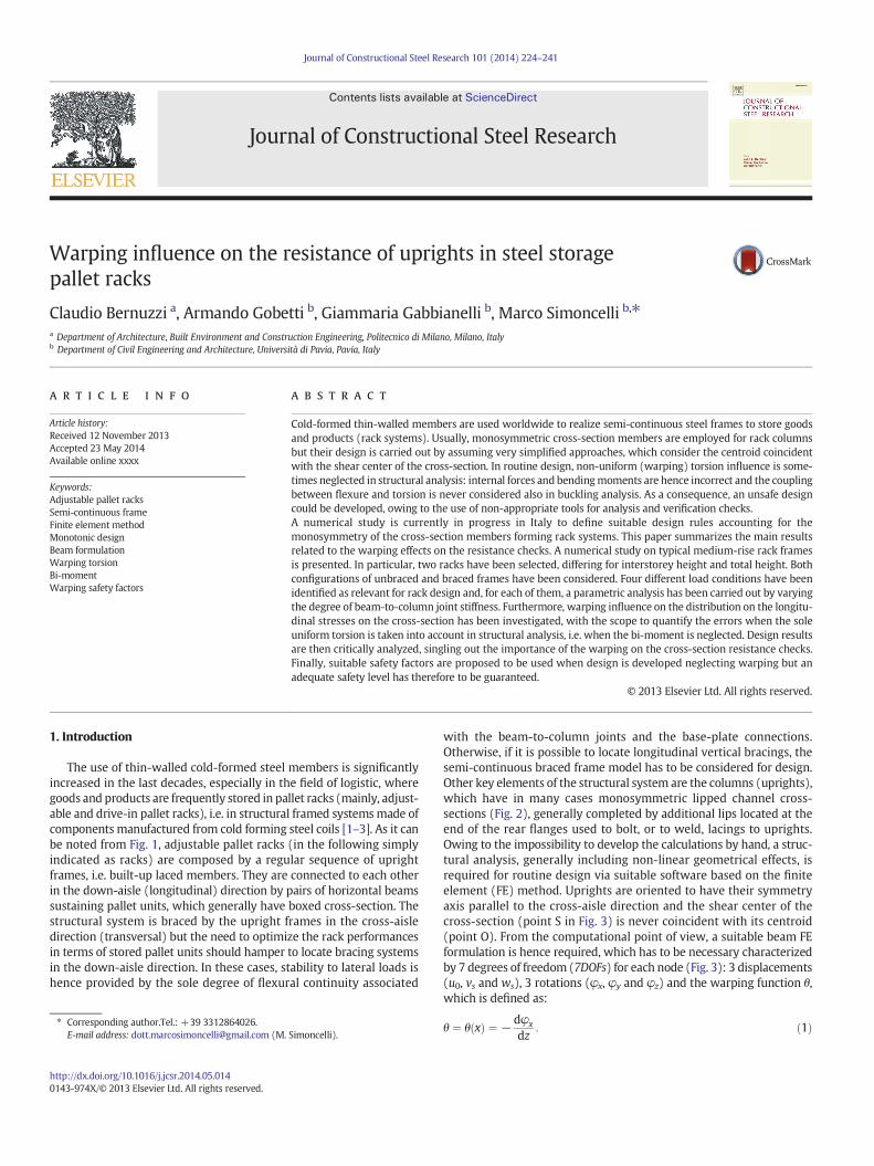
The use of thin-walled cold-formed steel members is significantlyincreased in the last decades, especially in the field of logistic, wheregoods and products are frequently stored in pallet racks (mainly, adjust-able and drive-in pallet racks), i.e. in structural framed systemsmade ofcomponents manufactured from cold forming steel coils [1–3]. As it canbe noted from Fig. 1, adjustable pallet racks (in the following simplyindicated as racks) are composed by a regular sequence of uprightframes, i.e. built-up laced members. They are connected to each otherin the down-aisle (longitudinal) direction by pairs of horizontal beamssustaining pallet units, which generally have boxed cross-section. Thestructural system is braced by the upright frames in the cross-aisledirection (transversal) but the need to optimize the rack performancesin terms of stored pallet units should hamper to locate bracing systemsin the down-aisle direction. In these cases, stability to lateral loads ishence provided by the sole degree of flexural continuity associated
Simoncelli).
with the beam-to-column joints and the base-plate connections.Otherwise, if it is possible to locate longitudinal vertical bracings, thesemi-continuous braced frame model has to be considered for design.Other key elements of the structural system are the columns (uprights),which have in many cases monosymmetric lipped channel cross-sections (Fig. 2), generally completed by additional lips located at theend of the rear flanges used to bolt, or to weld, lacings to uprights.Owing to the impossibility to develop the calculations by hand, a struc-tural analysis, generally including non-linear geometrical effects, isrequired for routine design via suitable software based on the finiteelement (FE) method. Uprights are oriented to have their symmetryaxis parallel to the cross-aisle direction and the shear center of thecross-section (point S in Fig. 3) is never coincident with its centroid(point O). From the computational point of view, a suitable beam FEformulation is hence required, which has to be necessary characterizedby 7 degrees of freedom (7DOFs) for each node (Fig. 3): 3 displacements(u0, vs and ws), 3 rotations (φx, φy and φz) and the warping function θ,which is defined as:
θ ¼ θ xð Þ ¼ −dφx
dz: ð1Þ
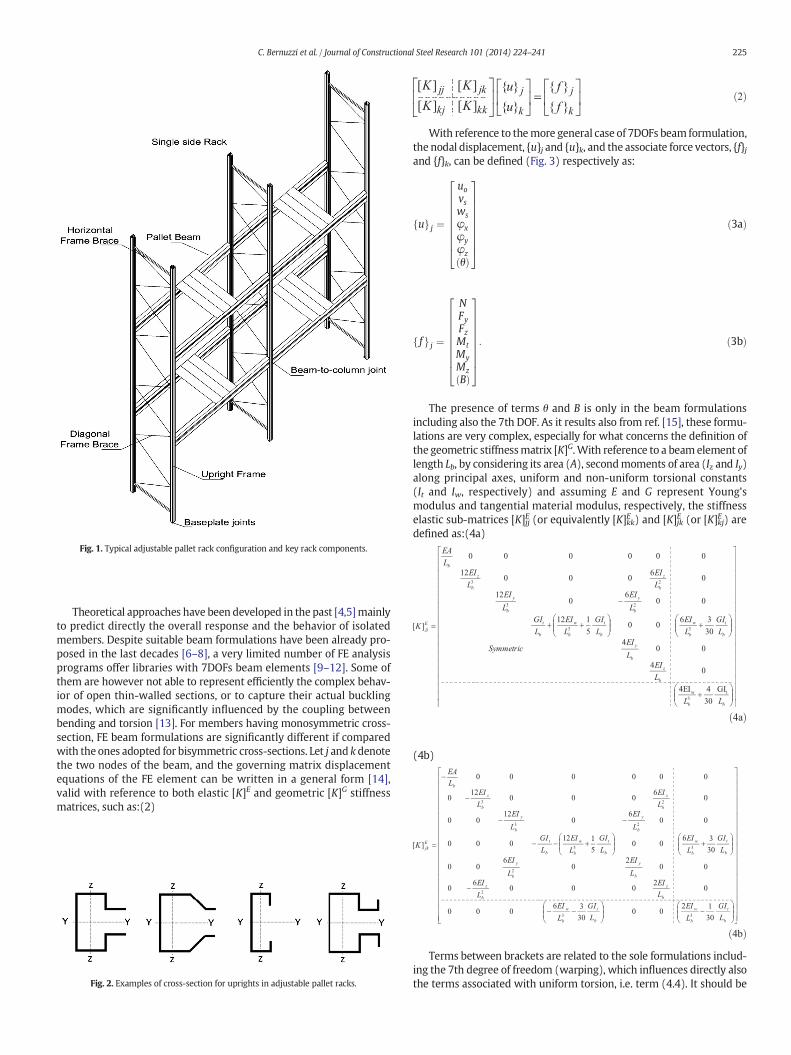
Fig. 1. Typical adjustable pallet rack configuration and key rack components.
225C. Bernuzzi et al. / Journal of Constructional Steel Research 101 (2014) 224–241
Theoretical approaches have been developed in the past [4,5]mainlyto predict directly the overall response and the behavior of isolatedmembers. Despite suitable beam formulations have been already pro-posed in the last decades [6–8], a very limited number of FE analysisprograms offer libraries with 7DOFs beam elements [9–12]. Some ofthem are however not able to represent efficiently the complex behav-ior of open thin-walled sections, or to capture their actual bucklingmodes, which are significantly influenced by the coupling betweenbending and torsion [13]. For members having monosymmetric cross-section, FE beam formulations are significantly different if comparedwith the ones adopted for bisymmetric cross-sections. Let j and k denotethe two nodes of the beam, and the governing matrix displacementequations of the FE element can be written in a general form [14],valid with reference to both elastic [K]E and geometric [K]G stiffnessmatrices, such as:(2)
Fig. 2. Examples of cross-section for uprights in adjustable pallet racks.
ð2Þ
With reference to themore general case of 7DOFs beam formulation,the nodal displacement, {u}j and {u}k, and the associate force vectors, {f}jand {f}k, can be defined (Fig. 3) respectively as:
uf g j ¼
uovswsφxφyφzθð Þ
2666666664
3777777775ð3aÞ
ff g j ¼
NFyFzMtMyMzBð Þ
2666666664
3777777775: ð3bÞ
The presence of terms θ and B is only in the beam formulationsincluding also the 7th DOF. As it results also from ref. [15], these formu-lations are very complex, especially for what concerns the definition ofthe geometric stiffnessmatrix [K]G.With reference to a beam element oflength Lb, by considering its area (A), secondmoments of area (Iz and Iy)along principal axes, uniform and non-uniform torsional constants(It and Iw, respectively) and assuming E and G represent Young'smodulus and tangential material modulus, respectively, the stiffnesselastic sub-matrices [K]jjE (or equivalently [K]kkE ) and [K]jkE (or [K]kjE ) aredefined as:(4a)
ð4aÞ
(4b)
ð4bÞTerms between brackets are related to the sole formulations includ-
ing the 7th degree of freedom (warping), which influences directly alsothe terms associated with uniform torsion, i.e. term (4.4). It should be
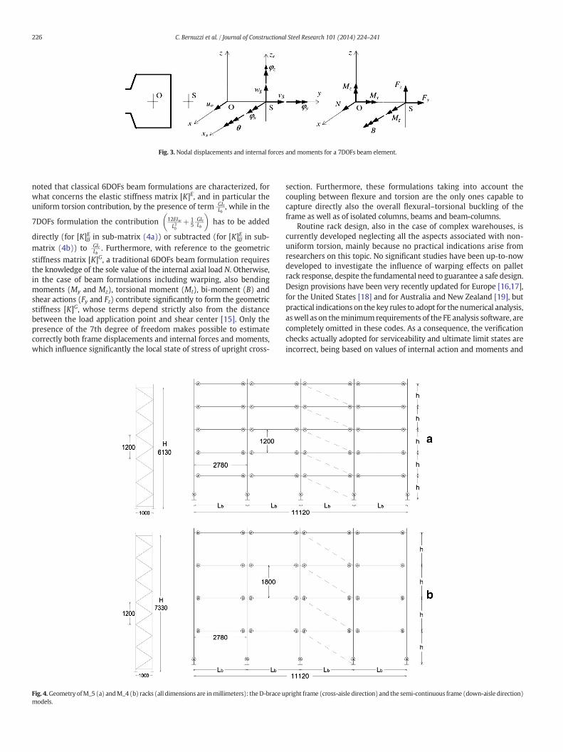
Fig. 3. Nodal displacements and internal forces and moments for a 7DOFs beam element.
226 C. Bernuzzi et al. / Journal of Constructional Steel Research 101 (2014) 224–241
noted that classical 6DOFs beam formulations are characterized, forwhat concerns the elastic stiffness matrix [K]E, and in particular theuniform torsion contribution, by the presence of term GIt
Lb, while in the
7DOFs formulation the contribution 12EIwL3b
þ 15
GItLb
� �has to be added
directly (for [K]jjE in sub-matrix (4a)) or subtracted (for [K]jjE in sub-matrix (4b)) to GIt
Lb. Furthermore, with reference to the geometric
stiffness matrix [K]G, a traditional 6DOFs beam formulation requiresthe knowledge of the sole value of the internal axial load N. Otherwise,in the case of beam formulations including warping, also bendingmoments (My and Mz), torsional moment (Mt), bi-moment (B) andshear actions (Fy and Fz) contribute significantly to form the geometricstiffness [K]G, whose terms depend strictly also from the distancebetween the load application point and shear center [15]. Only thepresence of the 7th degree of freedom makes possible to estimatecorrectly both frame displacements and internal forces and moments,which influence significantly the local state of stress of upright cross-
Fig. 4.Geometry ofM_5 (a) andM_4 (b) racks (all dimensions are inmillimeters): the D-brace umodels.
section. Furthermore, these formulations taking into account thecoupling between flexure and torsion are the only ones capable tocapture directly also the overall flexural–torsional buckling of theframe as well as of isolated columns, beams and beam-columns.
Routine rack design, also in the case of complex warehouses, iscurrently developed neglecting all the aspects associated with non-uniform torsion, mainly because no practical indications arise fromresearchers on this topic. No significant studies have been up-to-nowdeveloped to investigate the influence of warping effects on palletrack response, despite the fundamental need to guarantee a safe design.Design provisions have been very recently updated for Europe [16,17],for the United States [18] and for Australia and New Zealand [19], butpractical indications on the key rules to adopt for the numerical analysis,aswell as on theminimum requirements of the FE analysis software, arecompletely omitted in these codes. As a consequence, the verificationchecks actually adopted for serviceability and ultimate limit states areincorrect, being based on values of internal action and moments and
pright frame (cross-aisle direction) and the semi-continuous frame (down-aisle direction)

Fig. 5. The upright cross-section of the considered racks.
Fig. 6. Rotational stiffness of the beam-to-column joints considered in the analysis(dashed line).
Fig. 8. Summary of the parameters of the numerical analysis.
227C. Bernuzzi et al. / Journal of Constructional Steel Research 101 (2014) 224–241
displacements deriving from traditional FE analysis programs with6DOFs beam element. This should lead to an unsafe design but noindications are available to quantify the effective degree of reliability
Fig. 7. The considered load conditio
of a design carried out assuming these incorrect assumptions formonosymmetric cross-section members.
A research project is currently in progress in conjunction betweenthe Politecnico di Milano and the Università di Pavia on the warpinginfluence on the pallet rack design. A suitable finite element beamformulation developed by authors [15] has been implemented in Śiva[20], the FE analysis software used to obtain the results herein summa-rized. In a previous research of one of the authors [21], warpinginfluence on frame buckling and stability verification checks of beam-column has been already investigated by using a commercial FE analysisprogram [12]. This paper, which regards other rack configurations, isfocused on the resistance checks and presents main outcomes of anumerical analysis on medium-rise racks. Two different beam formula-tions have been considered in order to appraise the differences in theinternal forces and moments due to the presence of the 7th degree offreedom. Furthermore, design equations for both global and local resis-tance verification checks have been applied in order to evaluate the re-duction of the design safety level due to neglecting of warping. Finally,practical indications are proposed to designers in terms of suitablewarping safety factors γw to use when design is based on approachesneglecting warping torsion effects but an adequate safety level is how-ever required.
ns for the parametric analysis.
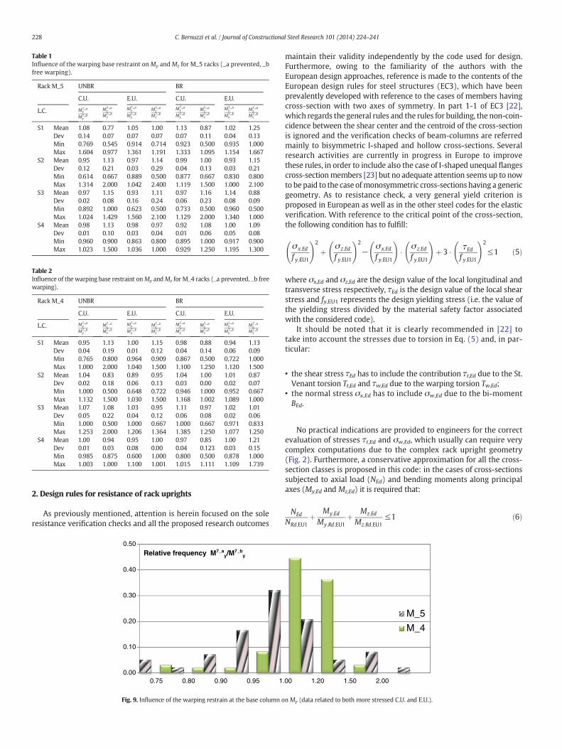
Table 1Influence of the warping base restraint onMy and Mz for M_5 racks (_a prevented, _bfree warping).
Rack M_5 UNBR BR
C.U. E.U. C.U. E.U.
L.C. M7 ay
M7 by
M7 az
M7 bz
M7 ay
M7 by
M7 az
M7 bz
M7 ay
M7 by
M7 az
M7 bz
M7 ay
M7 by
M7 az
M7 bz
S1 Mean 1.08 0.77 1.05 1.00 1.13 0.87 1.02 1.25Dev 0.14 0.07 0.07 0.07 0.07 0.11 0.04 0.13Min 0.769 0.545 0.914 0.714 0.923 0.500 0.935 1.000Max 1.604 0.977 1.361 1.191 1.333 1.095 1.154 1.667
S2 Mean 0.95 1.13 0.97 1.14 0.99 1.00 0.93 1.15Dev 0.12 0.21 0.03 0.29 0.04 0.13 0.03 0.21Min 0.614 0.667 0.889 0.500 0.877 0.667 0.830 0.800Max 1.314 2.000 1.042 2.400 1.119 1.500 1.000 2.100
S3 Mean 0.97 1.15 0.93 1.11 0.97 1.16 1.14 0.88Dev 0.02 0.08 0.16 0.24 0.06 0.23 0.08 0.09Min 0.892 1.000 0.623 0.500 0.733 0.500 0.960 0.500Max 1.024 1.429 1.560 2.100 1.129 2.000 1.340 1.000
S4 Mean 0.98 1.13 0.98 0.97 0.92 1.08 1.00 1.09Dev 0.01 0.10 0.03 0.04 0.01 0.06 0.05 0.08Min 0.960 0.900 0.863 0.800 0.895 1.000 0.917 0.900Max 1.023 1.500 1.036 1.000 0.929 1.250 1.195 1.300
Table 2Influence of the warping base restraint onMy andMz for M_4 racks (_a prevented, _b freewarping).
Rack M_4 UNBR BR
C.U. E.U. C.U. E.U.
L.C. M7 ay
M7 by
M7 az
M7 bz
M7 ay
M7 by
M7 az
M7 bz
M7 ay
M7 by
M7 az
M7 bz
M7 ay
M7 by
M7 az
M7 bz
S1 Mean 0.95 1.13 1.00 1.15 0.98 0.88 0.94 1.13Dev 0.04 0.19 0.01 0.12 0.04 0.14 0.06 0.09Min 0.765 0.800 0.964 0.909 0.867 0.500 0.722 1.000Max 1.000 2.000 1.040 1.500 1.100 1.250 1.120 1.500
S2 Mean 1.04 0.83 0.89 0.95 1.04 1.00 1.01 0.87Dev 0.02 0.18 0.06 0.13 0.03 0.00 0.02 0.07Min 1.000 0.500 0.648 0.722 0.946 1.000 0.952 0.667Max 1.132 1.500 1.030 1.500 1.168 1.002 1.089 1.000
S3 Mean 1.07 1.08 1.03 0.95 1.11 0.97 1.02 1.01Dev 0.05 0.22 0.04 0.12 0.06 0.08 0.02 0.06Min 1.000 0.500 1.000 0.667 1.000 0.667 0.971 0.833Max 1.253 2.000 1.206 1.364 1.385 1.250 1.077 1.250
S4 Mean 1.00 0.94 0.95 1.00 0.97 0.85 1.00 1.21Dev 0.01 0.03 0.08 0.00 0.04 0.123 0.03 0.15Min 0.985 0.875 0.600 1.000 0.800 0.500 0.878 1.000Max 1.003 1.000 1.100 1.001 1.015 1.111 1.109 1.739
228 C. Bernuzzi et al. / Journal of Constructional Steel Research 101 (2014) 224–241
2. Design rules for resistance of rack uprights
As previously mentioned, attention is herein focused on the soleresistance verification checks and all the proposed research outcomes
0.00
0.10
0.20
0.30
0.40
0.50
0.75 0.80 0.90 0.95 1
Relative frequency M7_ay/M
7_by
Fig. 9. Influence of the warping restrain at the base column o
maintain their validity independently by the code used for design.Furthermore, owing to the familiarity of the authors with theEuropean design approaches, reference is made to the contents of theEuropean design rules for steel structures (EC3), which have beenprevalently developed with reference to the cases of members havingcross-section with two axes of symmetry. In part 1-1 of EC3 [22],which regards the general rules and the rules for building, the non-coin-cidence between the shear center and the centroid of the cross-sectionis ignored and the verification checks of beam-columns are referredmainly to bisymmetric I-shaped and hollow cross-sections. Severalresearch activities are currently in progress in Europe to improvethese rules, in order to include also the case of I-shaped unequal flangescross-sectionmembers [23] but no adequate attention seems up to nowto be paid to the case ofmonosymmetric cross-sections having a genericgeometry. As to resistance check, a very general yield criterion isproposed in European as well as in the other steel codes for the elasticverification. With reference to the critical point of the cross-section,the following condition has to fulfill:
σ x;Ed
f y;EU1
!2
þ σ z;Ed
f y;EU1
!2
−σ x;Ed
f y;EU1
!� σ z;Ed
f y;EU1
!þ 3 � τEd
f y;EU1
!2
≤1 ð5Þ
where σx,Ed and σz,Ed are the design value of the local longitudinal andtransverse stress respectively, τEd is the design value of the local shearstress and fy,EU1 represents the design yielding stress (i.e. the value ofthe yielding stress divided by the material safety factor associatedwith the considered code).
It should be noted that it is clearly recommended in [22] totake into account the stresses due to torsion in Eq. (5) and, in par-ticular:
• the shear stress τEd has to include the contribution τt,Ed due to the St.Venant torsion Tt,Ed and τw,Ed due to the warping torsion Tw,Ed;
• the normal stress σx,Ed has to include σw,Ed due to the bi-momentBEd.
No practical indications are provided to engineers for the correctevaluation of stresses τt,Ed and σw,Ed, which usually can require verycomplex computations due to the complex rack upright geometry(Fig. 2). Furthermore, a conservative approximation for all the cross-section classes is proposed in this code: in the cases of cross-sectionssubjected to axial load (NEd) and bending moments along principalaxes (My,Ed and Mz,Ed) it is required that:
NEd
NRd;EU1þ My;Ed
My;Rd;EU1þ Mz;Ed
Mz;Rd;EU1≤1 ð6Þ
.00 1.20 1.50 2.00
M_5
M_4
nMy (data related to both more stressed C.U. and E.U.).
0.00
0.10
0.20
0.30
0.40
0.50
0.60
0.75 0.80 0.90 0.95 1.00 1.20 1.50 2.00
Relative frequency M7_az/M
7_bz
M_5
M_4
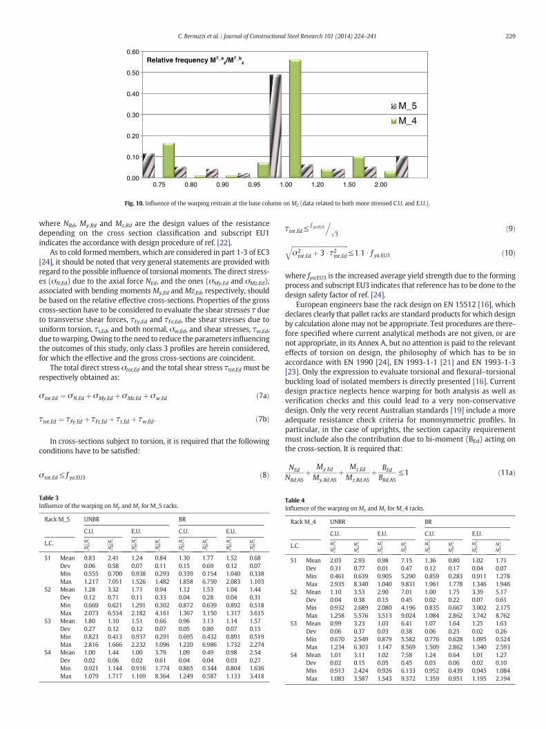
Fig. 10. Influence of the warping restrain at the base column on Mz (data related to both more stressed C.U. and E.U.).
229C. Bernuzzi et al. / Journal of Constructional Steel Research 101 (2014) 224–241
where NRd, My,Rd and Mz,Rd are the design values of the resistancedepending on the cross section classification and subscript EU1indicates the accordance with design procedure of ref. [22].
As to cold formedmembers, which are considered in part 1-3 of EC3[24], it should be noted that very general statements are provided withregard to the possible influence of torsional moments. The direct stress-es (σN,Ed) due to the axial force NEd, and the ones (σMy,Ed and σMz,Ed),associated with bending moments My,Ed and Mz,Ed, respectively, shouldbe based on the relative effective cross-sections. Properties of the grosscross-section have to be considered to evaluate the shear stresses τ dueto transverse shear forces, τFy,Ed and τFz,Ed, the shear stresses due touniform torsion, τt,Ed, and both normal, σw,Ed, and shear stresses, τw,Ed,due towarping. Owing to the need to reduce the parameters influencingthe outcomes of this study, only class 3 profiles are herein considered,for which the effective and the gross cross-sections are coincident.
The total direct stress σtot,Ed and the total shear stress τtot,Ed must berespectively obtained as:
σ tot;Ed ¼ σN;Ed þ σMy;Ed þ σMz;Ed þ σw;Ed ð7aÞ
τtot;Ed ¼ τFy;Ed þ τFz;Ed þ τt;Ed þ τw;Ed: ð7bÞ
In cross-sections subject to torsion, it is required that the followingconditions have to be satisfied:
σ tot;Ed≤ f ya;EU3 ð8Þ
Table 3Influence of the warping onMy and Mz for M_5 racks.
Rack M_5 UNBR BR
C.U. E.U. C.U. E.U.
L.C. M7y
M6y
M7z
M6z
M7y
M6y
M7z
M6z
M7y
M6y
M7z
M6z
M7y
M6y
M7z
M6z
S1 Mean 0.83 2.41 1.24 0.84 1.30 1.77 1.52 0.68Dev 0.06 0.58 0.07 0.11 0.15 0.69 0.12 0.07Min 0.555 0.700 0.938 0.293 0.339 0.154 1.040 0.338Max 1.217 7.051 1.526 1.482 1.858 6.750 2.083 1.103
S2 Mean 1.28 3.32 1.71 0.94 1.12 1.53 1.04 1.44Dev 0.12 0.71 0.11 0.33 0.04 0.28 0.04 0.31Min 0.669 0.621 1.291 0.302 0.872 0.639 0.892 0.518Max 2.073 6.534 2.182 4.161 1.367 3.150 1.317 3.615
S3 Mean 1.80 1.10 1.51 0.66 0.96 3.13 1.14 1.57Dev 0.27 0.12 0.12 0.07 0.05 0.80 0.07 0.15Min 0.823 0.413 0.937 0.291 0.695 0.432 0.891 0.519Max 2.816 1.666 2.232 1.096 1.220 6.986 1.732 2.274
S4 Mean 1.00 1.44 1.00 3.79 1.09 0.49 0.98 2.54Dev 0.02 0.06 0.02 0.61 0.04 0.04 0.03 0.27Min 0.921 1.144 0.916 1.774 0.865 0.344 0.804 1.636Max 1.079 1.717 1.169 8.364 1.249 0.587 1.133 3.418
τtot;Ed≤f ya;EU3
. ffiffi3
p ð9Þffiffiffiffiffiffiffiffiffiffiffiffiffiffiffiffiffiffiffiffiffiffiffiffiffiffiffiffiffiffiffiffiffiffiffiffiffiσ2
tot;Ed þ 3 � τ2tot;Edq
≤1:1 � f ya;EU3 ð10Þ
where fya,EU3 is the increased average yield strength due to the formingprocess and subscript EU3 indicates that reference has to be done to thedesign safety factor of ref. [24].
European engineers base the rack design on EN 15512 [16], whichdeclares clearly that pallet racks are standard products for which designby calculation alone may not be appropriate. Test procedures are there-fore specified where current analytical methods are not given, or arenot appropriate, in its Annex A, but no attention is paid to the relevanteffects of torsion on design, the philosophy of which has to be inaccordance with EN 1990 [24], EN 1993-1-1 [21] and EN 1993-1-3[23]. Only the expression to evaluate torsional and flexural–torsionalbuckling load of isolated members is directly presented [16]. Currentdesign practice neglects hence warping for both analysis as well asverification checks and this could lead to a very non-conservativedesign. Only the very recent Australian standards [19] include a moreadequate resistance check criteria for monosymmetric profiles. Inparticular, in the case of uprights, the section capacity requirementmust include also the contribution due to bi-moment (BEd) acting onthe cross-section. It is required that:
NEd
NRd;ASþ My;Ed
My;Rd;ASþ Mz;Ed
Mz;Rd;ASþ BEd
BRd;AS≤1 ð11aÞ
Table 4Influence of the warping onMy and Mz for M_4 racks.
Rack M_4 UNBR BR
C.U. E.U. C.U. E.U.
L.C. M7y
M6y
M7z
M6z
M7y
M6y
M7z
M6z
M7y
M6y
M7z
M6z
M7y
M6y
M7z
M6z
S1 Mean 2.03 2.93 0.98 7.15 1.36 0.80 1.02 1.71Dev 0.31 0.77 0.01 0.47 0.12 0.17 0.04 0.07Min 0.461 0.639 0.905 5.290 0.859 0.283 0.911 1.278Max 2.935 8.340 1.040 9.831 1.961 1.778 1.346 1.946
S2 Mean 1.10 3.53 2.90 7.01 1.00 1.75 3.39 5.17Dev 0.04 0.38 0.15 0.45 0.02 0.22 0.07 0.61Min 0.932 2.689 2.080 4.196 0.835 0.667 3.002 2.175Max 1.258 5.576 3.513 9.024 1.084 2.862 3.742 8.762
S3 Mean 0.99 3.23 1.03 6.41 1.07 1.64 1.25 1.63Dev 0.06 0.37 0.03 0.38 0.06 0.25 0.02 0.26Min 0.670 2.549 0.879 5.582 0.776 0.628 1.095 0.524Max 1.234 6.303 1.147 8.569 1.509 2.862 1.340 2.593
S4 Mean 1.01 3.11 1.02 7.58 1.24 0.64 1.01 1.27Dev 0.02 0.15 0.05 0.45 0.03 0.06 0.02 0.10Min 0.913 2.424 0.926 6.133 0.952 0.439 0.945 1.084Max 1.083 3.587 1.543 9.372 1.359 0.951 1.195 2.194
0.00
0.05
0.10
0.15
0.20
0.25
0.35 0.60 0.80 1.00 1.20 1.40 1.60 1.90 2.30 2.70 3.00
Relative frequency M7y/M6
y
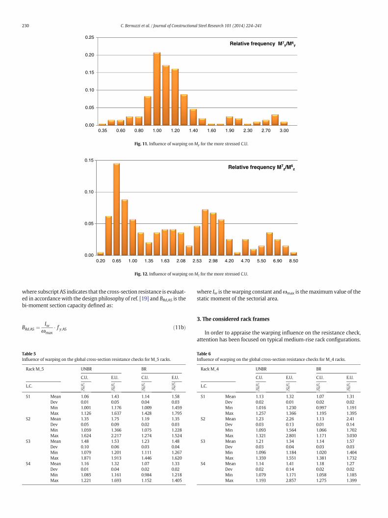
Fig. 11. Influence of warping onMy for the more stressed C.U.
0.00
0.05
0.10
0.15
0.20 0.65 1.00 1.35 1.63 2.08 2.53 2.98 4.20 4.70 5.50 6.90 8.50
Relative frequency M7z/M
6z
Fig. 12. Influence of warping onMz for the more stressed C.U.
230 C. Bernuzzi et al. / Journal of Constructional Steel Research 101 (2014) 224–241
where subscript AS indicates that the cross-section resistance is evaluat-ed in accordancewith the design philosophy of ref. [19] and BRd,AS is thebi-moment section capacity defined as:
BRd;AS ¼Iw
ωmax� f y;AS ð11bÞ
Table 5Influence of warping on the global cross-section resistance checks for M_5 racks.
Rack M_5 UNBR BR
C.U. E.U. C.U. E.U.
L.C. SI7GSI6G
SI7GSI6G
SI7GSI6G
SI7GSI6G
S1 Mean 1.06 1.43 1.14 1.58Dev 0.01 0.05 0.04 0.03Min 1.001 1.176 1.009 1.459Max 1.126 1.637 1.428 1.795
S2 Mean 1.35 1.75 1.19 1.35Dev 0.05 0.09 0.02 0.03Min 1.059 1.366 1.075 1.228Max 1.624 2.217 1.274 1.524
S3 Mean 1.48 1.53 1.23 1.48Dev 0.10 0.06 0.03 0.04Min 1.079 1.201 1.111 1.267Max 1.871 1.913 1.446 1.620
S4 Mean 1.16 1.32 1.07 1.33Dev 0.01 0.04 0.02 0.02Min 1.085 1.161 0.984 1.218Max 1.221 1.693 1.152 1.405
where Iw is thewarping constant andωmax is themaximum value of thestatic moment of the sectorial area.
3. The considered rack frames
In order to appraise the warping influence on the resistance check,attention has been focused on typical medium-rise rack configurations.
Table 6Influence of warping on the global cross-section resistance checks for M_4 racks.
Rack M_4 UNBR BR
C.U. E.U. C.U. E.U.
L.C. SI7GSI6G
SI7GSI6G
SI7GSI6G
SI7GSI6G
S1 Mean 1.13 1.32 1.07 1.31Dev 0.02 0.01 0.02 0.02Min 1.016 1.230 0.997 1.191Max 1.257 1.366 1.195 1.395
S2 Mean 1.23 2.26 1.13 2.41Dev 0.03 0.13 0.01 0.14Min 1.093 1.564 1.066 1.702Max 1.321 2.801 1.171 3.030
S3 Mean 1.21 1.34 1.14 1.57Dev 0.03 0.04 0.03 0.03Min 1.096 1.184 1.020 1.404Max 1.359 1.551 1.381 1.732
S4 Mean 1.14 1.41 1.18 1.27Dev 0.02 0.14 0.02 0.02Min 1.079 1.171 1.058 1.185Max 1.193 2.857 1.275 1.399

0.90
1.00
1.10
1.20
1.30
1.40
0.66 1.00 1.31 6.66 10.00 13.10
SI7G/SI6G
S1_a
S2_a
S3_a
S4_a
S1_b
S2_b
S3_b
S4_b
ρ
Fig. 13. Influence of warping on the global resistance check for the more stressed C.U. in M_4 UNBR racks.
0.90
1.00
1.10
1.20
1.30
1.40
0.66 1.00 1.31 6.66 10.00 13.10
SI7G/SI6G
S1_a
S2_a
S3_a
S4_a
S1_b
S2_b
S3_b
S4_b
ρ
Fig. 14. Influence of warping on the global resistance check for the more stressed C.U. in M_4 BR racks.
0.90
1.00
1.10
1.20
1.30
1.40
1.50
1.60
1.70
1.80
1.90
0.66 1.00 1.31 6.66 10.00 13.10
SI7G/SI6G
S1_a
S2_a
S3_a
S4_a
S1_b
S2_b
S3_b
S4_b
ρ
Fig. 15. Influence of warping on the global resistance check for the more stressed C.U. in M_5 UNBR racks.
231C. Bernuzzi et al. / Journal of Constructional Steel Research 101 (2014) 224–241

0.90
1.00
1.10
1.20
1.30
1.40
1.50
0.66 1.00 1.31 6.66 10.00 13.10
SI7G/SI6G
S1_a
S2_a
S3_a
S4_a
S1_b
S2_b
S3_b
S4_b
ρ
Fig. 16. Influence of warping on the global verification check for the more stressed C.U. in M_5 BR racks.
232 C. Bernuzzi et al. / Journal of Constructional Steel Research 101 (2014) 224–241
This study, which comprised of structural analyses and design verifica-tions, has been carried out by considering the following key parameters:
1. the frame geometry (Fig. 4): two racks differing for their interstoreyheight (h) and overall height (H) were considered:
• rack M_4 is characterized by 4 storeys with h = 1.80 m and H =7.33 m;
• rack M_5 is characterized by 5 storeys with h = 1.20 m and H =6.13 m.For both frames, a 5 equal bay rack configuration (bay span of2.78 m) was considered. Only the case of D-brace upright frame
0.00
0.02
0.04
0.06
0.08
0.10
0.12
0.14
1.00 1.15 1.25 1.44 1.56
Fig. 17. Influence of warping in M_5 racks for global
0
0.02
0.04
0.06
0.08
0.1
0.12
0.14
0.16
1.00 1.11 1.18 1.30 1.38 1.50 1
Fig. 18. Influence of warping in M_4 racks for global
(Fig. 4), with alternate tension or compression diagonals, wasincluded in this study with a panel height of 1.20 m, owing tothe very limited influence of the type as well as of the height ofthe upright frame panel, as demonstrated in a previous researchof one of the authors [20]. As to the rack components, they havebeen selected with reference to the most common adoptedsolutions. Upright cross-section is presented in Fig. 5, while rectan-gular hollow sections have been considered for the upright lacings(30 × 30× 3mm) and for the beams (100 × 50× 3mm). Owing tothe need of limiting the number of variables of the analysis, allcross-section profiles have been selected in order to belong to
1.68 1.80 1.90 1.93 2.30
Relative frequency SI7G/SI6G
resistance check (more stressed C.U. and E.U.).
.62 1.88 2.08 2.45 2.61 2.75 3.00
Relative frequency SI7G/SI6G
resistance check (more stressed C.U. and E.U.).
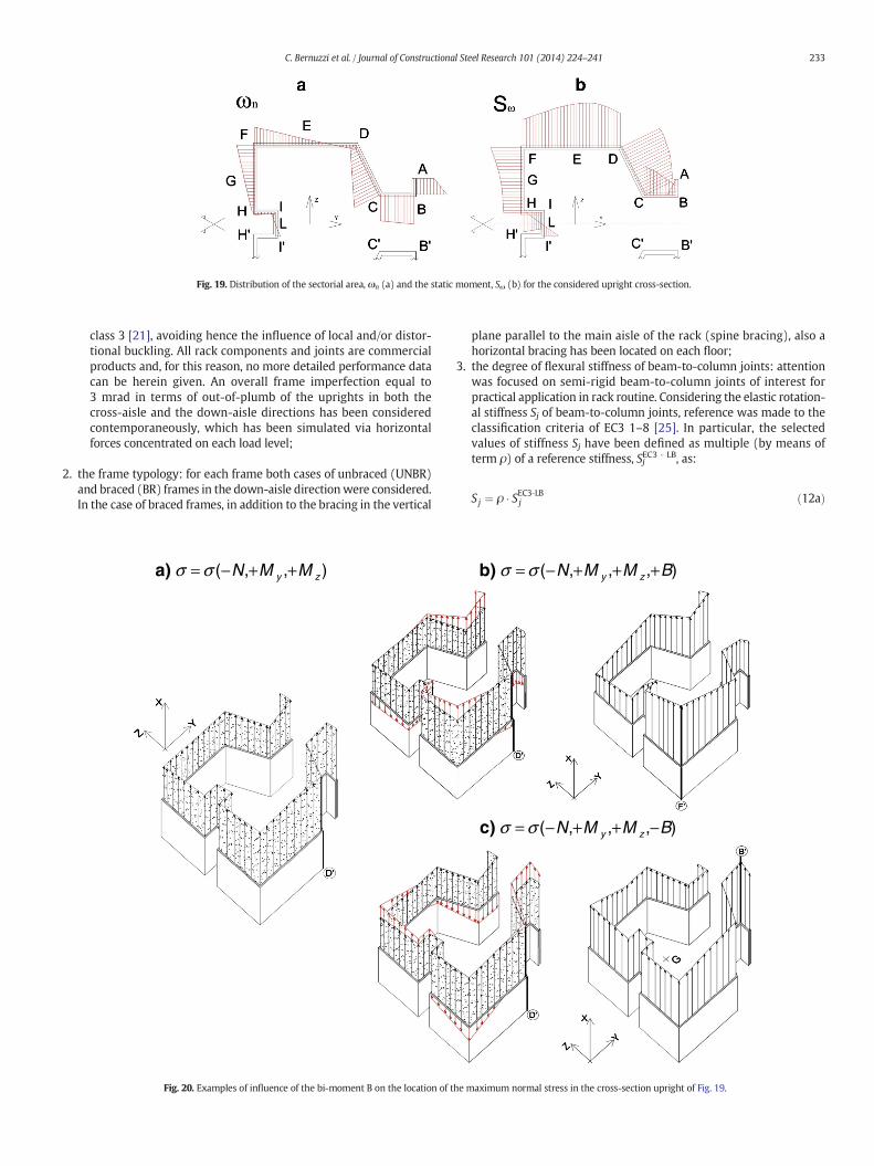
Fig. 19. Distribution of the sectorial area, ωn (a) and the static moment, Sω (b) for the considered upright cross-section.
233C. Bernuzzi et al. / Journal of Constructional Steel Research 101 (2014) 224–241
class 3 [21], avoiding hence the influence of local and/or distor-tional buckling. All rack components and joints are commercialproducts and, for this reason, no more detailed performance datacan be herein given. An overall frame imperfection equal to3 mrad in terms of out-of-plumb of the uprights in both thecross-aisle and the down-aisle directions has been consideredcontemporaneously, which has been simulated via horizontalforces concentrated on each load level;
2. the frame typology: for each frame both cases of unbraced (UNBR)and braced (BR) frames in the down-aisle directionwere considered.In the case of braced frames, in addition to the bracing in the vertical
a)
Fig. 20. Examples of influence of the bi-moment B on the location of t
plane parallel to the main aisle of the rack (spine bracing), also ahorizontal bracing has been located on each floor;
3. the degree of flexural stiffness of beam-to-column joints: attentionwas focused on semi-rigid beam-to-column joints of interest forpractical application in rack routine. Considering the elastic rotation-al stiffness Sj of beam-to-column joints, reference was made to theclassification criteria of EC3 1–8 [25]. In particular, the selectedvalues of stiffness Sj have been defined as multiple (by means ofterm ρ) of a reference stiffness, SjEC3 ‐ LB, as:
Sj ¼ ρ � SEC3‐LBj ð12aÞ
b)
c)
he maximum normal stress in the cross-section upright of Fig. 19.

Table 7Influence of thewarping on the pointwhere themaximumstress acts on the cross section.
N Mz My σ = σ(N, My, Mz) point B σ = σ(N, My, Mz, B) point
− + + D′ + F′− B′
− + − D + B− F
− − + F′ + F′− B′
− − − F + B− F
Table 9Influence of the warping on the local stress resistance checks for M_4 racks.
Rack M_4 UNBR BR
C.U. E.U. C.U. E.U.
L.C. SI7σSI6σ
SI7σSI6σ
SI7σSI6σ
SI7σSI6σ
S1 Mean 1.12 1.07 1.06 1.08Dev 0.02 0.02 0.02 0.02Max 1.227 1.187 1.146 1.207Min 1.007 1.006 0.984 1.013
S2 Mean 1.07 1.81 1.00 1.95Dev 0.02 0.09 0.01 0.09Max 1.143 2.145 1.029 2.351Min 0.987 1.286 0.932 1.513
S3 Mean 1.04 1.08 1.05 1.21Dev 0.02 0.02 0.03 0.02Max 1.174 1.316 1.258 1.374Min 0.953 1.035 0.936 1.129
S4 Mean 1.02 1.03 1.11 1.03Dev 0.01 0.01 0.02 0.01Max 1.052 1.123 1.176 1.092Min 0.979 1.005 0.992 0.986
234 C. Bernuzzi et al. / Journal of Constructional Steel Research 101 (2014) 224–241
where SjEC3 ‐ LB is the stiffness corresponding to the transition
between flexible and semi-rigid joint domains, defined by the codeas:
SEC3‐LBj ¼ 0:5E � IbLb
ð12bÞ
where E is the Young's modulus, Ib is the second moment of area ofbeam section, Lb is the beam length and ρ is the stiffness parameterwhich has been considered, in the present study, ranging from 0.67to 13.10, as it appears from Fig. 6 where they are plotted in themoment (M)–rotation (ϕ) reference system, together with theupper limit of the semi-rigid domain associated with both unbraced(ρ = 50) and braced (ρ = 16) frames. All the considered values ofjoint stiffness, which are typical of the possible configurationsof beam-to-column joints associated with the considered upright(Fig. 5), have been deduced by test reports related to beam-to-column joint tests executed in accordance with ref. [16].
Table 8Influence of the warping on the local stress resistance checks for M_5 racks.
Rack M_5 UNBR BR
C.U. E.U. C.U. E.U.
L.C. SI7σSI6σ
SI7σSI6σ
SI7σSI6σ
SI7σSI6σ
S1 Mean 1.06 1.18 1.11 1.29Dev 0.01 0.03 0.03 0.03Max 1.125 1.383 1.362 1.508Min 0.991 1.001 0.989 1.150
S2 Mean 1.16 1.41 1.07 1.13Dev 0.04 0.07 0.01 0.02Max 1.395 1.838 1.148 1.259Min 0.968 1.104 0.981 1.004
S3 Mean 1.30 1.26 1.06 1.18Dev 0.09 0.04 0.02 0.03Max 1.638 1.489 1.225 1.343Min 0.949 1.013 0.922 1.060
S4 Mean 1.02 1.07 1.03 1.10Dev 0.01 0.05 0.01 0.01Max 1.056 1.541 1.107 1.153Min 0.990 0.982 0.957 1.053
4. the load condition (Fig. 7): rack bays have been considered directlyloaded by pallets and a uniform distributed load acting on eachbeam was assumed. Four different load conditions have beenidentified as representative for rack design:
a) fully loaded condition, i.e. each bay is loaded (in the followingindicated as S1);
b) alternate loaded condition giving rise to single curvature onuprights when the rack is braced (S2);
c) external bays only loaded on each load levels (S3);d) full load on the rackwith the exception of few lowest beam level,
near the middle of the racks (S4), as indicated in Fig. 7.It should be noted that S1 and S4 load conditions are recom-mended also by rack standard codes, while the other ones havebeen identified on the basis of the expertise of the authors inrack design.
The sole case of semi-rigid joints has been considered, owing to theneed of limiting the number of variables influencing warping effects.The value of the base-plate joint stiffness corresponds to 0.11 and to0.17 times the flexural upright stiffness EIu
h
� �for M_5 and M_4 frames,
respectively.Finite element analysis has been executed by Śiva software [26]: in
addition to the beam element formulation including warping, i.e., thebeam formulation with 7DOFs [15], Śiva's library offers also the moretraditional beam element based on the classical 6DOFs beam formula-tion [14]. Both types of analysis, i.e. with 6DOFs and 7DOFs beam ele-ment formulations have been executed for all the considered rackframes. Warping restraint has been considered free for the upright topas well as for the bracing upright members, also in correspondence ofthe intersection with upright. As to the end of beams, due to the avail-able forms of end connectors, warping has been considered blocked.Owing to the different possibilities to connect the upright end to the in-dustrial floor, i.e. due to the different types of available connections,both cases of column base with warping totally prevented (_a) or free(_b) have been considered. Fig. 8 presents the analysis layout explainingsymbols used to present main research outcomes.
4. Influence of warping on internal forces and moments
At first attention has been focused on the influence of the warpingrestraint at the column bases related to the 7DOFs beam analyses.
Tables 1 and 2 present the ratio ofM7 ay
M7 by
andM7 az
M7 bz
between the bendingmo-
ment (My7 or Mz
7) obtained by considering prevented (_a) or free (_b)the column base warping. Mean value and standard deviation for all
0.90
1.00
1.10
1.20
1.30
0.66 1.00 1.31 6.66 10.00 13.10
S1_a
S2_a
S3_a
S4_a
S1_b
s2_b
S3_b
S4_b
SI7σ /SI6σ
ρ
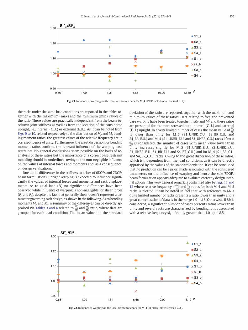
Fig. 21. Influence of warping on the local resistance check for M_4 UNBR racks (more stressed C.U.).
235C. Bernuzzi et al. / Journal of Constructional Steel Research 101 (2014) 224–241
the racks under the same load conditions are reported in the tables to-gether with the maximum (max) and the minimum (min) values ofthe ratio. These values are practically independent from the beam-to-column joint stiffness as well as from the location of the consideredupright, i.e., internal (C.U.) or external (E.U.). As it can be noted fromFigs. 9 to 10, related respectively to the distribution ofMy andMz bend-ing moment ratios, the greatest values of the relative frequency are incorrespondence of unity. Furthermore, the great dispersion for bendingmoment ratios confirms the relevant influence of the warping baserestraints. No general conclusions seem possible on the basis of re-analysis of these ratios but the importance of a correct base restraintmodeling should be underlined, owing to the non-negligible influenceon the values of internal forces and moments and, as a consequence,on design verifications.
Due to the differences in the stiffness matrices of 6DOFs and 7DOFsbeam formulations, upright warping is expected to influence signifi-cantly the values of internal forces and moments and rack displace-ments. As to axial load (N) no significant differences have beenobserved while influence of warping is non-negligible for shear forces(Fy and Fz), despite the fact that generally shear doesn't represent a pa-rameter governing rack design, as shown in the following. As to bendingmoments My and Mz, a summary of the differences can be directly ap-praised via Tables 3 and 4 related to M7
y
M6yand M7
z
M6zratio, where data are
grouped for each load condition. The mean value and the standard
0.90
1.00
1.10
1.20
1.30
0.66 1.00 1.31
SI7σ /SI6σ
Fig. 22. Influence of warping on the local resistance
deviation of the ratio are reported, together with the maximum andminimum values of these ratios. Data related to free and preventedbase warping have been treated together inMy
7andMz
7and these ratios
are presented for the more stressed both internal (C.U.) and external(E.U.) upright. In a very limited number of cases the mean value of M7
y
M6y
is lower than unity for M_5 (S1_UNBR_C.U., S3_BR_C.U. andS4_BR_E.U.) and M_4 (S1_UNBR_E.U. and S3_UNBR_C.U.) racks. If ratioM7
z
M6zis considered, the number of cases with mean value lower than
unity increases slightly for M_5 (S1_UNBR_E.U., S2_UNBR_E.U.,S3_UNBR_E.U., S1_BR_E.U. and S4_BR_C.U.) and for M_4 (S1_BR_C.U.and S4_BR_C.U.) racks. Owing to the great dispersion of these ratios,which is independent from the load conditions, as it can be directlyappraised by the values of the standard deviation, it can be concludedthat no prediction can be a priori made associated with the consideredparameters on the influence of warping and hence the sole 7DOFsbeam formulation appears adequate to evaluate correctly design inter-nal actions. This very general remark is confirmed also by Figs. 11 and12 where relative frequency of M7
y
M6yand M7
z
M6zratios for both M_4 and M_5
racks is plotted. It can be noted in fact that with reference to My aquite limited number of racks presents a ratio lower than unity and agreat concentration of data is in the range 1.0–1.15. Otherwise, if Mz isconsidered, a significant number of cases presents ratios lower thanunity and several racks are characterized by bending ratios associatedwith a relative frequency significantly greater than 1.0 up to 8.5.
6.66 10.00 13.10
S1_a
S2_a
S3_a
S4_a
S1_b
s2_b
S3_b
S4_b
ρ
check for M_4 BR racks (more stressed C.U.).
0.90
1.00
1.10
1.20
1.30
1.40
1.50
1.60
1.70
0.66 1.00 1.31 6.66 10.00 13.10
S1_a
S2_a
S3_a
S4_a
S1_b
s2_b
S3_b
S4_b
SI7σ /SI6σ
ρ
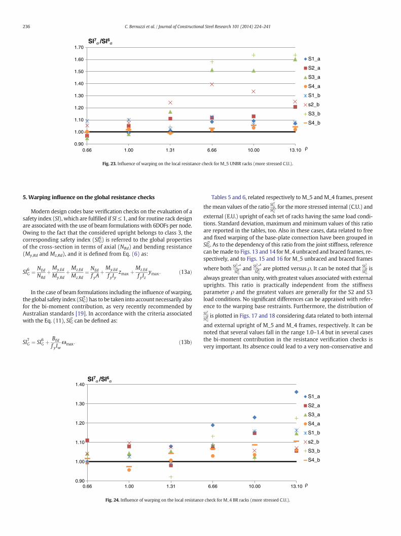
Fig. 23. Influence of warping on the local resistance check for M_5 UNBR racks (more stressed C.U.).
236 C. Bernuzzi et al. / Journal of Constructional Steel Research 101 (2014) 224–241
5. Warping influence on the global resistance checks
Modern design codes base verification checks on the evaluation of asafety index (SI), which are fulfilled if SI≤ 1, and for routine rack designare associated with the use of beam formulations with 6DOFs per node.Owing to the fact that the considered upright belongs to class 3, thecorresponding safety index (SIG6) is referred to the global propertiesof the cross-section in terms of axial (NRd) and bending resistance(My,Rd and Mz,Rd), and it is defined from Eq. (6) as:
SI6G ¼ NEd
NRdþMy;Ed
My;RdþMz;Ed
Mz;Rd¼ NEd
f yAþMy;Ed
f yIyzmax þ
Mz;Ed
f yIzymax: ð13aÞ
In the case of beam formulations including the influence of warping,the global safety index (SIG7) has to be taken into account necessarily alsofor the bi-moment contribution, as very recently recommended byAustralian standards [19]. In accordance with the criteria associatedwith the Eq. (11), SIG7 can be defined as:
SI7G ¼ SI6G þ BEd
f yIwωmax: ð13bÞ
0.90
1.00
1.10
1.20
1.30
1.40
0.66 1.00 1.31
SI7σ /SI6σ
Fig. 24. Influence of warping on the local resistance
Tables 5 and 6, related respectively to M_5 and M_4 frames, present
themean values of the ratio SI7GSI6G, for themore stressed internal (C.U.) and
external (E.U.) upright of each set of racks having the same load condi-tions. Standard deviation, maximum and minimum values of this ratioare reported in the tables, too. Also in these cases, data related to freeand fixed warping of the base-plate connection have been grouped inSIG
7. As to the dependency of this ratio from the joint stiffness, referencecan bemade to Figs. 13 and 14 forM_4 unbraced and braced frames, re-spectively, and to Figs. 15 and 16 for M_5 unbraced and braced frames
where both SI7 aG
SI6Gand SI7 b
G
SI6Gare plotted versus ρ. It can be noted that SI7G
SI6Gis
always greater than unity, with greatest values associatedwith externaluprights. This ratio is practically independent from the stiffnessparameter ρ and the greatest values are generally for the S2 and S3load conditions. No significant differences can be appraised with refer-ence to the warping base restraints. Furthermore, the distribution ofSI7GSI6G
is plotted in Figs. 17 and 18 considering data related to both internal
and external upright of M_5 and M_4 frames, respectively. It can benoted that several values fall in the range 1.0–1.4 but in several casesthe bi-moment contribution in the resistance verification checks isvery important. Its absence could lead to a very non-conservative and
6.66 10.00 13.10
S1_a
S2_a
S3_a
S4_a
S1_b
s2_b
S3_b
S4_b
ρ
check for M_4 BR racks (more stressed C.U.).

0.00
0.10
0.20
0.30
0.40
0.50
0.95 1.00 1.16 1.28 1.40 1.52 1.64 1.89 2.16 2.50
Relative frequency SI7σ /SI6σ
Fig. 25. Influence of warping on the local resistance check for M_5 racks (more stressed C.U. and E.U.).
237C. Bernuzzi et al. / Journal of Constructional Steel Research 101 (2014) 224–241
dangerous design, being the safety index overestimated up to approxi-mately 3 times.
6. Warping influence on the local resistance checks
Normal σw,Ed(y, z) and shear τw,Ed(y, z) stresses due to the bi-moment BEd in a general point P of co-ordinate (y,z) defined with refer-ence to the cross-section centroid (Fig. 3), can be expressed as:
σw;Ed y; zð Þ ¼ BEd
Iw�ω y; zð Þ ð14aÞ
τw;Ed y; zð Þ ¼ Tw
Iw� Sω y; zð Þ
tð14bÞ
where Tw represents the non-uniform torsional moment, t is the thick-ness of the cross-section and all the other symbols have been previouslydefined.
As alreadymentioned, the use of Eq. (13b) in resistance checks couldlead to a slightly conservative design, owing to the fact that the maxi-mum of the sectorial area (ωmax), as well as of its first moment of area(Sω,max), is not at the same location where stresses due to bending mo-ments reach the maximum values. As a consequence, it should appearmore appropriate, in order to guarantee an optimal use of the material,to evaluate the local distribution of the normal stresses summing thevalues of the stresses occurring at the same point of the cross-section.
0.00
0.10
0.20
0.30
0.40
0.50
0.98 0.99 1.00 1.01 1.10 1.14 1.20 1.30
Fig. 26. Influence of warping on the local resistance ch
The distributions of the sectorial area ω(y, z) and of its first momentSω(y, z) are presented in Fig. 19 for the cross-section geometry of theconsidered upright. With reference to the sole normal stresses, owingto the influence of warping, the non-coincidence between the pointswhere normal stress is maximum if a 6DOFs or a 7DOFs beam formula-tion is used as can be noted in Fig. 20. If reference is made to the signconventions of Fig. 3, maximum normal stress is in point D′ if the soleaxial load and positive bending moments are considered. Otherwise, ifbi-moment BEd acts on cross-section, maximum stress is in correspon-dence of point F′ (BEd N 0) or point B′ if (BEd b 0). More in general,Table 7 indicates the point where normal stress is maximum whenaxial load is negative (compression) andmoments are positive or nega-tive. It appears that if the normal stresses due to warping are neglected,σ = σ(N, My, Mz), or considered, σ = σ(N, My, Mz, Bw), the point withthe maximum stress coincides only in the following two cases: all themoments negative or when Mz is negative and My and B are positive.Otherwise a moderate member over sizing is possible whenEq. (13b)) is used.
Neglecting thepresence ofmaterial safety factors γm, whichdependson the considered code, resistance safety index based on the local stressvalue SIσ can be defined, in accordance with Eq. (10), as:
SIσ ¼ffiffiffiffiffiffiffiffiffiffiffiffiffiffiffiffiffiffiffiffiffiffiffiffiffiffiffiffiffiffiffiffiffiffiffiffiffiffiffiffiffiffiffiffiffiffiffiffiffiffiffiffiffiffiffiffiffiffiσ tot y; zð Þ½ �2 þ 3 � τtot y; zð Þ½ �2
qf y
: ð15Þ
1.44 1.60 1.66 1.72 2.00 2.06 2.20 2.50
Relative frequency SI7σ /SI6σ
eck for M_4 racks (more stressed C.U. and E.U.).

Table 10Influence of the resistance check criteria on the safety index for M_5 racks.
Rack M_5 UNBR BR
C.U. E.U. C.U. E.U.
L.C. SI7GSI7σ
SI7GSI7σ
SI7GSI7σ
SI7GSI7σ
S1 Mean 1.01 1.20 1.03 1.24Dev 0.01 0.02 0.00 0.02Max 1.037 1.297 1.059 1.338Min 1.002 1.064 1.016 1.129
S2 Mean 1.17 1.25 1.11 1.19Dev 0.02 0.03 0.02 0.03Max 1.287 1.378 1.194 1.332Min 1.006 1.096 1.000 1.083
S3 Mean 1.14 1.22 1.13 1.25Dev 0.01 0.02 0.03 0.01Max 1.179 1.305 1.246 1.309Min 1.069 1.114 1.000 1.192
S4 Mean 1.15 1.23 1.04 1.24Dev 0.01 0.02 0.00 0.03Max 1.188 1.295 1.057 1.402Min 1.105 1.097 1.022 1.124
238 C. Bernuzzi et al. / Journal of Constructional Steel Research 101 (2014) 224–241
In the following, for the generic point P of co-ordinates (y,z), the ver-ification checks associated with the use of both 6DOFs and 7DOFs beamelements can be expressed in terms of safety index, as:
SI6σ ¼ffiffiffiffiffiffiffiffiffiffiffiffiffiffiffiffiffiffiffiffiffiffiffiffiffiffiffiffiffiffiffiffiffiffiffiffiffiffiffiffiffiffiffiffiffiffiffiffiffiffiffiffiffiffiffiffiffiffiffiffiffiσ6
tot y; zð Þ� �2 þ 3 � τ6tot y; zð Þ� �2qf y
¼
ffiffiffiffiffiffiffiffiffiffiffiffiffiffiffiffiffiffiffiffiffiffiffiffiffiffiffiffiffiffiffiffiffiffiffiffiffiffiffiffiffiffiffiffiffiffiffiffiffiffiffiffiffiffiffiffiffiffiffiffiffiffiffiffiffiffiffiffiffiffiffiffiffiffiffiffiffiffiffiffiffiffiffiσ6
tot y; zð Þ� �2 þ 3 � τFy y; zð Þ þ τFz y; zð Þh i2rf y
ð16aÞ
SI7σ ¼ffiffiffiffiffiffiffiffiffiffiffiffiffiffiffiffiffiffiffiffiffiffiffiffiffiffiffiffiffiffiffiffiffiffiffiffiffiffiffiffiffiffiffiffiffiffiffiffiffiffiffiffiffiffiffiffiffiffiffiffiffiσ7
tot y; zð Þ� �2 þ 3 � τ7tot y; zð Þ� �2qf y
¼
¼
ffiffiffiffiffiffiffiffiffiffiffiffiffiffiffiffiffiffiffiffiffiffiffiffiffiffiffiffiffiffiffiffiffiffiffiffiffiffiffiffiffiffiffiffiffiffiffiffiffiffiffiffiffiffiffiffiffiffiffiffiffiffiffiffiffiffiffiffiffiffiffiffiffiffiffiffiffiffiffiffiffiffiffiffiffiffiffiffiffiffiffiffiffiffiffiffiffiffiffiffiffiffiffiffiffiffiffiffiffiffiffiffiffiffiffiffiffiσ6
tot y; zð Þ þ σw;Ed y; zð Þh i2 þ 3 � τ6tot y; zð Þ þ σw;Ed y; zð Þ
h i2rf y
ð16bÞ
where terms τFy(y, z) and τFz(y, z) represent the tangential stresses dueto the shear forces Fy and Fz, respectively.
As previously mentioned, the contribution of Fy and Fz to theresistance verification check is very modest and the influence of theterm τtot6 (y, z) on the evaluation of SIσ6 is very limited, not greater than
Table 11Influence of the resistance check criteria on the safety index for M_4 racks.
Rack M_4 UNBR BR
C.U. E.U. C.U. E.U.
L.C. SI7GSI7σ
SI7GSI7σ
SI7GSI7σ
SI7GSI7σ
S1 Mean 1.01 1.23 1.01 1.22Dev 0.01 0.02 0.01 0.02Max 1.059 1.316 1.053 1.325Min 1.001 1.119 0.999 1.130
S2 Mean 1.15 1.25 1.12 1.18Dev 0.01 0.01 0.01 0.02Max 1.197 1.307 1.145 1.266Min 1.075 1.197 `1.080 0.996
S3 Mean 1.17 1.24 1.08 1.30Dev 0.01 0.02 0.01 0.03Max 1.215 1.313 1.153 1.391Min 1.117 1.132 1.038 1.114
S4 Mean 1.11 1.24 1.07 1.23Dev 0.01 0.02 0.00 0.02Max 1.140 1.300 1.086 1.293Min 1.086 1.132 1.051 1.146
0.1% of the maximum normal stress. If the bi-moment contribution isconsidered to evaluate τtot7 (y, z), shear stress influence on SIσ
7 is greaterthan in the previous case, but, however, remains negligible, not greaterthan 0.5%. For each of the points of the upright cross-section indicated inFig. 7 the local state of stress has been evaluated. As in the previouscases, by considering both SIσ
7 _ a and SIσ7 _ b grouped in term SIσ
7,
Tables 8 and 9 present for M_5 and M_4 racks the mean value of SI7σSI6σ
ratio for each set of similar frames having the same load condition. Stan-dard deviation with the maximum and minimum values of the ratio isreported in these tables, too. As for the global safety index SIG, also inthe case of index SIσ reference has been made to the more stressed in-ternal (C.U.) and external (E.U.) column. In Figs. 21 and 22, the ratioSI7σSI6σ
for the more stressed uprights is plotted versus ρ for M_4 unbraced
and braced frames, respectively. Corresponding Figs. 23 and 24 presentthe data for M_5 frames. Previous comments related to the global safety
index SIσ are confirmed also in the case of local safety index SIσ. RatioSI7σSI6σ
is independent on the joint stiffness and the more relevant warping in-fluence is for external uprights.
The maximum values of the relative frequency plotted in Figs. 25(M_4 racks) and 26 (M_5 racks) are in the range 1.08–1.12 despitethe fact that a great dispersion can however be observed. In a very lim-ited number of cases, the ratio SI7σ
SI6σis slightly lower than unity. This is due
to the greater flexibility of the rackmodeled via a 7DOFs beam formula-tion to which correspond slightly lower values of the bendingmomentsacting on the cross-section; only in these very few cases a moderateconservative design could hence be obtained via a 6DOFs beam formu-lation. In all the other cases it appears fundamental to take adequatelyinto accountwarping, owing to great influence also on the local verifica-tion safety index SIσ
7, which is in some cases up to 2.5 times SIσ6.
7. A proposal for routine design
Results previously presented underline the non-negligible influenceof warping effects in resistance verification checks, confirming the needto analyze racks as well as every frame with monosymmetric cross-section members via suitable analysis software programs havingadequate 7DOFs beam element formulations. Two different criteria forthe resistance verification of the cross-section have been previouslyconsidered to evaluate the global (SIG) and the local (SIσ) safety index.Tables 10 and 11 summarize the data related to the distribution of theratio SI7G
SI7σ, in order to appraise the concrete influence of the verifications
criteria on design. As expected SIσ7 is slightly lower than SIG
7 owing tothe more accurate evaluation of the state of stresses on cross-section.
Figs. 27 and 28 plot the distribution of SI7GSI7σ
ratio for M_5 and M_4racks, respectively. For internal uprights (C.U.) the global safety indexfor resistance check is slightly greater than the local one.With referenceto the external uprights (E.U.) these differences are significantly greater,approximately up to 30% and appear to be independent from the loadcondition.
Correct design of these types of structures should result verycomplex for many engineers and practitioners: in addition to theavailability of an appropriate software analysis, it is in fact also requiredto have an adequate knowledge on the theory of thin-walled memberbehavior [4–6] and the ability to determinate non-uniform torsionalstiffness coefficients aswell as theWagner coefficients for very complexcross-section geometries (Fig. 2). As alternative to a refined designusing 7DOFs beam formulation, traditional procedures based on6DOFs beam structural analysis should however still be used by increas-ing the safety index (SI6) via a suitable safety factor γw accounting forthe neglected warping. An evaluation of (SI7) should be obtained as:
SI7 ¼ γw � SI6: ð17Þ

0.00
0.05
0.10
0.15
0.20
0.25
0.30
1.00 1.05 1.11 1.12 1.14 1.20 1.22 1.23 1.25 1.28 1.32 1.40 1.50
Relative frequency SI7G/SI7σ
Fig. 27. Influence of the resistance check criteria on safety index of M_5 racks (more stressed C.U. and E.U.).
239C. Bernuzzi et al. / Journal of Constructional Steel Research 101 (2014) 224–241
To this purpose, extensive parametric analysis similar to the onedescribed in the present paper should allow to evaluate statically thevalue of γw. Nevertheless, as an example of practical application of thismethodology, the data of this research have been statically consideredto evaluate safety warping factors γw.
With reference to the limit state design philosophy [25] the distribu-tion of all data governing design can to be considered of a Gaussian typeand the upper characteristic value of safety factor γw can be defined as:
γw ¼ γw;95 ¼ eγw þ kst � sw ð18Þ
where eγw is the mean value of the distribution of the ratio SI7
SI6, sw is its
standard deviation and kst is the coefficient to evaluate the 95% fractilevalue at a confidence level of 75% [16,25].
Tables 12 and 13 contain the values of γwG and γw
σ respectively. Bothindices have been evaluated for central (C.U.) and external (E.U.)uprights as well as for all the uprights by considering each frame typol-ogy. As to general remarks, it can be noted that:
• safety factors for C.U. are significantly lower than the ones of E.U.;• if all the uprights are treated together, γw for unbraced frames isgreater than the one for braced frames;
• factors γw associated with local cross-section verifications check (γwσ)
are slightly lower than the one associated with (γwG).
It can be concluded that the range of variation of these γw factors issignificantly wide. A proposal of the authors for warping safety factorsγwG and γw
σ to be used in routine design is summarized in Table 14
0.00
0.05
0.10
0.15
0.20
0.25
0.30
1.01 1.02 1.03 1.05 1.10 1
Fig. 28. Influence of the resistance check criteria on safet
considering the cases of a unique value for all the uprights or values sep-arated for external (E.U.) and internal (C.U.) uprights.
8. Conclusions
This paper deals with medium-rise racks, which are semi-continuous frames realized by monosymmetric cross-section membersused as uprights, and attention has been focused on the influence of thewarping on the resistance checks. The response of several geometricconfigurations of interest for rack practice has been considered; a para-metric study has been carried out by using two FE beam formulationsdiffering in the number of nodal degrees of freedom considered, bothimplemented in an analysis software for academic use developed by au-thors [15,20]. With reference to the resistance check approaches usedworldwide, design results of a traditional 6DOFs analysis have beencompared with those from a more refined formulation consideringwarping effects, i.e. characterized by 7DOFs per node. It has been dem-onstrated thatwarping plays a very important rule on the rack responseand this reflects directly on the safety level of design, which is signifi-cantly overestimated if warping is neglected, especially for externaluprights.
In order to reduce the overestimation of the safety due to the use ofinadequate beam formulations, the values of safety factor accounting forwarping γw have been evaluated, and Table 14 presents a proposal ofthe authors for an immediate use in resistance design verifications.
Furthermore, it should be noted that these research outcomes,which have been obtained with reference to racks, have a more general
.17 1.19 1.22 1.30 1.38 1.40
Relative frequency SI7G/SI7σ
y index of M_4 racks (more stressed C.U. and E.U.).
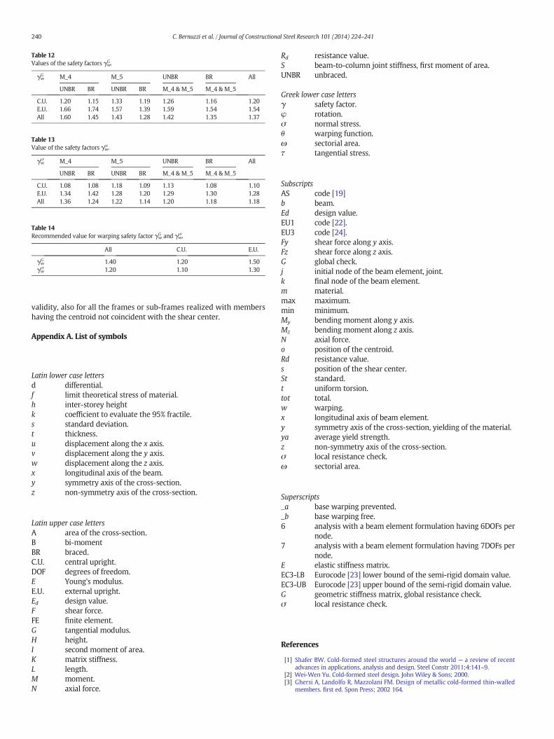
Table 12Values of the safety factors γw
G .
γwG M_4 M_5 UNBR BR All
UNBR BR UNBR BR M_4 & M_5 M_4 & M_5
C.U. 1.20 1.15 1.33 1.19 1.26 1.16 1.20E.U. 1.66 1.74 1.57 1.39 1.59 1.54 1.54All 1.60 1.45 1.43 1.28 1.42 1.35 1.37
Table 13Value of the safety factors γw
σ .
γwσ M_4 M_5 UNBR BR All
UNBR BR UNBR BR M_4 & M_5 M_4 & M_5
C.U. 1.08 1.08 1.18 1.09 1.13 1.08 1.10E.U. 1.34 1.42 1.28 1.20 1.29 1.30 1.28All 1.36 1.24 1.22 1.14 1.20 1.18 1.18
Table 14Recommended value for warping safety factor γw
G and γwσ .
All C.U. E.U.
γwG 1.40 1.20 1.50
γwσ 1.20 1.10 1.30
240 C. Bernuzzi et al. / Journal of Constructional Steel Research 101 (2014) 224–241
validity, also for all the frames or sub-frames realized with membershaving the centroid not coincident with the shear center.
Appendix A. List of symbols
Latin lower case lettersd differential.f limit theoretical stress of material.h inter-storey heightk coefficient to evaluate the 95% fractile.s standard deviation.t thickness.u displacement along the x axis.v displacement along the y axis.w displacement along the z axis.x longitudinal axis of the beam.y symmetry axis of the cross-section.z non-symmetry axis of the cross-section.
Latin upper case lettersA area of the cross-section.B bi-momentBR braced.C.U. central upright.DOF degrees of freedom.E Young's modulus.E.U. external upright.Ed design value.F shear force.FE finite element.G tangential modulus.H height.I second moment of area.K matrix stiffness.L length.M moment.N axial force.
Rd resistance value.S beam-to-column joint stiffness, first moment of area.UNBR unbraced.
Greek lower case lettersγ safety factor.φ rotation.σ normal stress.θ warping function.ω sectorial area.τ tangential stress.
SubscriptsAS code [19]b beam.Ed design value.EU1 code [22].EU3 code [24].Fy shear force along y axis.Fz shear force along z axis.G global check.j initial node of the beam element, joint.k final node of the beam element.m material.max maximum.min minimum.My bending moment along y axis.Mz bending moment along z axis.N axial force.o position of the centroid.Rd resistance value.s position of the shear center.St standard.t uniform torsion.tot total.w warping.x longitudinal axis of beam element.y symmetry axis of the cross-section, yielding of the material.ya average yield strength.z non-symmetry axis of the cross-section.σ local resistance check.ω sectorial area.
Superscripts_a base warping prevented._b base warping free.6 analysis with a beam element formulation having 6DOFs per
node.7 analysis with a beam element formulation having 7DOFs per
node.E elastic stiffness matrix.EC3-LB Eurocode [23] lower bound of the semi-rigid domain value.EC3-UB Eurocode [23] upper bound of the semi-rigid domain value.G geometric stiffness matrix, global resistance check.σ local resistance check.
References
[1] Shafer BW. Cold-formed steel structures around the world — a review of recentadvances in applications, analysis and design. Steel Constr 2011;4:141–9.
[2] Wei-Wen Yu. Cold-formed steel design. John Wiley & Sons; 2000.[3] Ghersi A, Landolfo R, Mazzolani FM. Design of metallic cold-formed thin-walled
members. first ed. Spon Press; 2002 164.
241C. Bernuzzi et al. / Journal of Constructional Steel Research 101 (2014) 224–241
[4] Timoshenko SP, Gere JM. Theory of elastic stability. 2nd ed. New-York: McGraw Hill;1961.
[5] Vlasov VZ. Thin walled elastic beams. 2nd ed. Jerusalem: Israel Program for ScientificTransactions; 1961.
[6] Chen WF, Atzuta T. Theory of beam-columns: vol. 2 Space behaviour and design.McGraw Hill; 1977.
[7] Turkalj G, Brnic J, Prpic-Orsic J. Large rotation analysis of elastic thin walled beam-type structures using ESA approach. Comput Struct 2003;81:1851–64.
[8] Battini JM. Co-rotational beam elements in instability problems. Technical reportfrom Royal Institute of Technology Department of Mechanics — Stockholm,Sweden; January 2002.
[9] ABAQUS/STANDARD user's manual version 6.8. USA: Hibbit, Karlsson and Sorensen;2006.
[10] LS-DYNA, http://www.ls-dyna.com/1_pages/1lsdyna.htm.[11] The SOFiSTiK FEM Packages, http://www.sofistik.com/en/.[12] ConSteel 7.0: “Finite-Element-Program”, Consteel Solutions Ltd, http://www.
consteel.hu.[13] Mohri F, Brouki A, Roth JC. Theoretical and numerical stability analyses of unre-
strained, mono-symmetric thin-walled beams. J Constr Steel Res 2003;59:63–90.[14] Bathe K, Wilson EL. Numerical methods in finite element analysis. Prentice-Hall;
1976.[15] Bernuzzi C, Gobetti A. An innovative finite element formulation for analysis of beam
element with thin-walled monosymmetric section; 2014 [in preparation].[16] CEN, EN 15512. Steel static storage systems — adjustable pallet racking systems —
principles for structural design. CEN European Committee for Standardization;2009 [137 pp.].
[17] Federation Européenne de Manutention. FEM 10.2.08—recommendations for thedesign of static steel storage pallet racks in seismic conditions; September 2010[version 1.00].
[18] RMI. H 16.1— specification for the design, testing and utilization of industrial steelstorage racks. RMI — Rack Manufacturers Institute; 2008 [59 pp.].
[19] Australian Standards. AS 4084 — steel storage racking. Australia: AS Standards;2012.
[20] Bernuzzi C, Gobetti A, Gabbianelli G, Simoncelli M. Śiva-System of Incremental andVibration Analysis: software for a finite element analysis for beam with warping in-fluence; 2014 [in preparation].
[21] Bernuzzi C, Pieri A, Squadrito V. Warping influence on the monotonic design ofunbraced steel storage pallet racks. Thin-Walled Struct 2014;79:71–82.
[22] European Committee for Standardization CEN, Eurocode 3 — design of steel struc-tures — part 1-1: general rules and rules for buildings, CEN European Committeefor Standardization.
[23] Bernuzzi C, Cordova B. Further possible developments of the general part ofEurocode 3 (UNI EN 1993-1-1). XXIII Italian conference on Steel Structures, Torino(I); September 2013 [in Italian].
[24] European Committee for Standardization. CEN, Eurocode 3 — design of steel struc-tures — part 1-3: design of cold formed members. Brussels: CEN; May 2005.
[25] European Committee for Standardization, CEN. Eurocode 0 — basis of structural de-sign. CEN; December, 2005.
[26] European Committee for Standardization CEN. Eurocode 3 — design of steel struc-tures — part 1-8: design of joints. Brussels: CEN; May 2005.