seismic exploration of subglacial lakes · seismic exploration of subglacial lakes abstract. ... è...
TRANSCRIPT
GNGTS – Atti del 22° Convegno Nazionale / 13.08
S. Picotti
Istituto Nazionale di Oceanografia e di Geofisica Sperimentale – OGS, Trieste
SEISMIC EXPLORATION OF SUBGLACIAL LAKES
Abstract. The recent focusing of Antarctic research on subglacial lakes implies a deeper understanding of their geological context (i.e. their relation to basement structures, internal configuration of the sediments, sedimentary processes, and occurrence of free-gas or gas-hydrates bearing layers). It is therefore essential to achieve an adequate coverage of seismic reflection profiles. The OGS (Istituto Nazionale di Oceanografia e Geofisica Sperimentale) has recently undertaken a research project within PNRA (Programma Nazionale di Ricerche in Antartide). The objective of the project is to design and test a large-offset multichannel seismic reflection survey aimed at the definition of Antarctic subglacial lakes on the East Antarctic ice sheet. The classic multifold technique of seismic reflection survey, widely used in land and marine acquisition, has never been applied to this purpose. This is due to the technical and logistical difficulties imposed by the local extreme environment (very low temperature, difficulties in the transport of equipment, coupling surface of sources and receivers). Considering the remarkable technical and operative problems on the Antarctic plateau, to minimise the resources, in terms of instrumentation and time, is fundamental. Therefore, a modelling study has been recently performed in order to characterise the seismic response of a subglacial lake and to design a proper seismic acquisition geometry. The seismic acquisition test phase of the project was performed in Antarctica (near the Dome C base) in December 2003, at the completion of the modelling study.
ESPLORAZIONE SISMICA DI LAGHI SUBGLACIALI Riassunto. La ricerca in Antartide si è recentemente orientata sullo studio dei laghi subglaciali. Al fine di comprendere il contesto geologico dei laghi subglaciali (la loro relazione con strutture del basamento, la configurazione interna dei sedimenti, i processi sedimentari, e la distribuzione eventuale di livelli a gas libero o idrato) è essenziale disporre di una copertura adeguata di profili sismici a riflessione multicanale. Nell’ambito di un progetto finanziato dal PNRA (Programma Nazionale di Ricerche in Antartide), l’OGS (Istituto Nazionale di Oceanografia e Geofisica Sperimentale) si occupa attualmente di pianificare e testare dei rilievi sismici a riflessione multicanale mirati alla definizione dei laghi subglaciali sulla calotta antartica orientale. La tecnica classica d’acquisizione sismica a copertura multipla, comunemente utilizzata per l’esplorazione marina e terrestre, non è mai stata applicata ai laghi subglaciali. Ciò è dovuto essenzialmente alle difficoltà tecniche e logistiche indotte dalle condizioni ambientali estreme (bassa temperatura, difficoltà di trasporto in zona della strumentazione, accoppiamento di sorgenti e ricevitori con la superficie). Dati i notevoli problemi tecnici ed operativi sul plateau antartico, è di fondamentale importanza minimizzare le risorse, in termini di strumentazione e tempo. A tal proposito è stato recentemente condotto uno studio per caratterizzare la risposta sismica di un lago subglaciale, e progettare una adeguata geometria d’acquisizione sismica. La prova strumentale in Antartide è stata condotta (vicino alla base di Dome C) nel mese di dicembre del 2003, a completamento dello studio teorico.
INTRODUCTION
Within a broader project funded by the PNRA (Programma Nazionale di Ricerche in Antartide) on the Exploration of Antarctic subglacial lakes on the East Antarctic ice sheet, coordinated by the Università di Milano, the OGS (Istituto Nazionale di Oceanografia e Geofisica Sperimentale) leads a research unit whose objective is to design and to execute multichannel seismic reflection surveys aimed to define the geometry of these lakes. A large number of subglacial lakes were discovered in Antarctica (Fig. 1a) using georadar methods (Siegert et al., 1996;

GNGTS – Atti del 22° Convegno Nazionale / 13.08
Siegert, 2000), so today the problem is to understand their inner structures and geologic context, and also their potentiality as sources of information for the reconstruction of the glacial history of Antarctica. The interest of these studies is aimed in particular to the seismic exploration of Vostok and Concordia Lakes (Fig. 1a) for the following reasons:
1. Both these lakes are located in a strategic position, very close respectively to
the stations of Dome C (Italy-France) and Vostok (Russia), that can supply the essential logistic facilities.
2. Vostok lake lies at a mean depth of nearly 4 km, some hundred of meters below the base of a well, and is therefore the first candidate for a direct exploration and sampling.
3. Up to now, the existence of Concordia lake is merely speculative. In fact, the only experimental evidence is the flat shape of the glacial cap basement, defined using Radio-Echo Soundings (RES) methods. The final response of the existence of Concordia lake can be provided only by the seismic survey method.
In order to reconstruct the origin and the evolution of the subglacial lakes, the
analysis of sediments on the bottom is an important source of information. This analysis regards the depositional mechanisms, the sedimentation rates, and the eventual correlation with the alternation of glacial and interglacial phases. The interest extends also to the possible presence of micro-organisms, to studies related to paleo-environmental problems and to the flow of geothermal heat (analysis of the ice-core) and, finally, to the possible presence of meteoritic material, cosmic powder and free gas or gas-hydrate.
The seismic reflection surveys carried out in 1964 (Kapitsa et al., 1996) and those realised by the PMGRE (Polar Marine Geological Research Expedition) and RAE (Russian Antarctic Expedition) in the period 1995-2001 (Masolov et al., 1999; Fig. 1b), allowed the localisation of a sediment package in some zones of Vostok lake, interposed between the layer of water and the basement.
Fig. 1 - a) The distribution of subglacial lakes on the Antarctic Ice Sheet. b) The seismic data acquired on Lake Vostok (see Masolov et al. ,1999 for more details).
GNGTS – Atti del 22° Convegno Nazionale / 13.08
However, the knowledge of the distribution of the sedimentary sequences and their depositional geometry is rather fragmentary or at all absent. The techniques employed in these surveys are the Vertical Seismic Profiling (VSP) and Reflection Seismic Soundings (RSS). The classic multifold technique of seismic reflection survey, commonly used for the marine and land exploration, has never been applied to subglacial lake exploration. This is essentially due to the technical and logistic difficulties, induced by the environmental extreme conditions (low temperature, difficulties in the transport of the instrumentation on the spot, coupling of sources and receivers with the surface). Moreover, the multifold technique requires an adequate coverage of seismic multichannel reflection profiles over the lake.
With the purpose of driving a future seismic multifold reflection survey on Concordia and Vostok lakes, a modelling study has been recently undertaken at OGS to design a suitable seismic acquisition geometry. The extreme conditions of operativity on the Antarctic plateau, requires a preventive analysis in order to avoid a waste of resources. This study, performed using a synthetic model, reveals that the stronger reflection are associated to ice/water, water/sediment, and sediment/basement interfaces. The polarity of reflections, and Amplitude Versus Angle (AVA) analysis can help to discriminate between reflective events, even in cases of small thickness of the lake sediment fill (Carcione and Gei, 2003). Once the reflected events are identified on the seismic prestack data, it is possible to recover the velocity model and the geometry of the lake by reflection tomography. Good results are assured using during the seismic acquisition simultaneously large and small offset (distance between source and receivers). As showed in the following sections, some simulations carried out with a seismic tomographic software (CAT-3D) realised by a research team of the OGS allowed us to optimise the seismic acquisition geometry, in order to obtain the better results using the minimum amount of resources.
TRAVEL-TIMES TOMOGRAPHY
The adopted tomographic algorithm, based on the SIRT method and the minimum-time ray tracing, can estimate the velocity field and the reflector structure in sequence (Vesnaver et al., 1999). The model is a blocky one, with voxels (3D case) or pixels (2D case) within which the velocity is assumed constant. The base and top of the pixels/voxels define the reflecting/refracting interfaces, that may be curved and dipping interfaces.
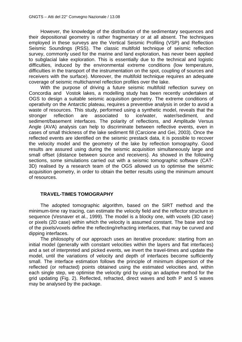
The philosophy of our approach uses an iterative procedure: starting from an initial model (generally with constant velocities within the layers and flat interfaces) and a set of interpreted and picked events, we invert the travel-times and update the model, until the variations of velocity and depth of interfaces become sufficiently small. The interface estimation follows the principle of minimum dispersion of the reflected (or refracted) points obtained using the estimated velocities and, within each single step, we optimise the velocity grid by using an adaptive method for the grid updating (Fig. 2). Reflected, refracted, direct waves and both P and S waves may be analysed by the package.
GNGTS – Atti del 22° Convegno Nazionale / 13.08
Fig. 2 - A flowchart of the travel-times tomography procedure adopted.
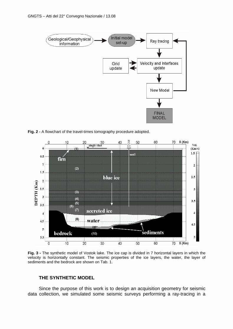
Fig. 3 - The synthetic model of Vostok lake. The ice cap is divided in 7 horizontal layers in which the velocity is horizontally constant. The seismic properties of the ice layers, the water, the layer of sediments and the bedrock are shown on Tab. 1.
THE SYNTHETIC MODEL Since the purpose of this work is to design an acquisition geometry for seismic
data collection, we simulated some seismic surveys performing a ray-tracing in a
GNGTS – Atti del 22° Convegno Nazionale / 13.08
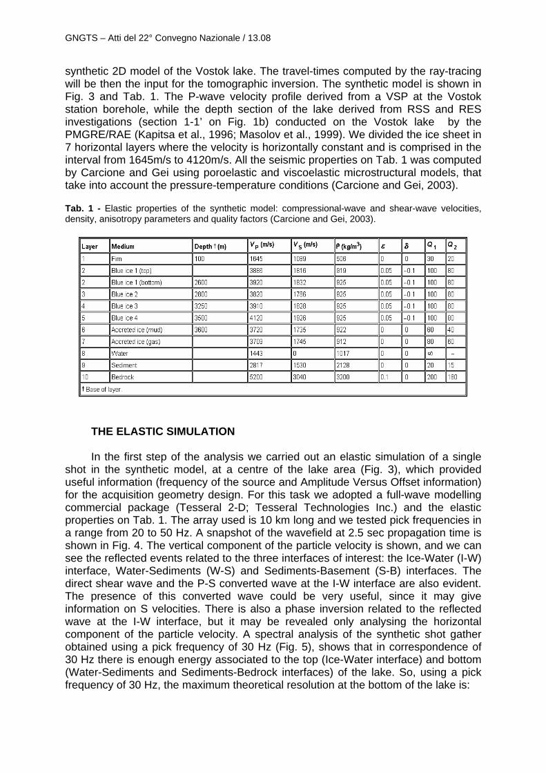
synthetic 2D model of the Vostok lake. The travel-times computed by the ray-tracing will be then the input for the tomographic inversion. The synthetic model is shown in Fig. 3 and Tab. 1. The P-wave velocity profile derived from a VSP at the Vostok station borehole, while the depth section of the lake derived from RSS and RES investigations (section 1-1’ on Fig. 1b) conducted on the Vostok lake by the PMGRE/RAE (Kapitsa et al., 1996; Masolov et al., 1999). We divided the ice sheet in 7 horizontal layers where the velocity is horizontally constant and is comprised in the interval from 1645m/s to 4120m/s. All the seismic properties on Tab. 1 was computed by Carcione and Gei using poroelastic and viscoelastic microstructural models, that take into account the pressure-temperature conditions (Carcione and Gei, 2003). Tab. 1 - Elastic properties of the synthetic model: compressional-wave and shear-wave velocities, density, anisotropy parameters and quality factors (Carcione and Gei, 2003).
THE ELASTIC SIMULATION
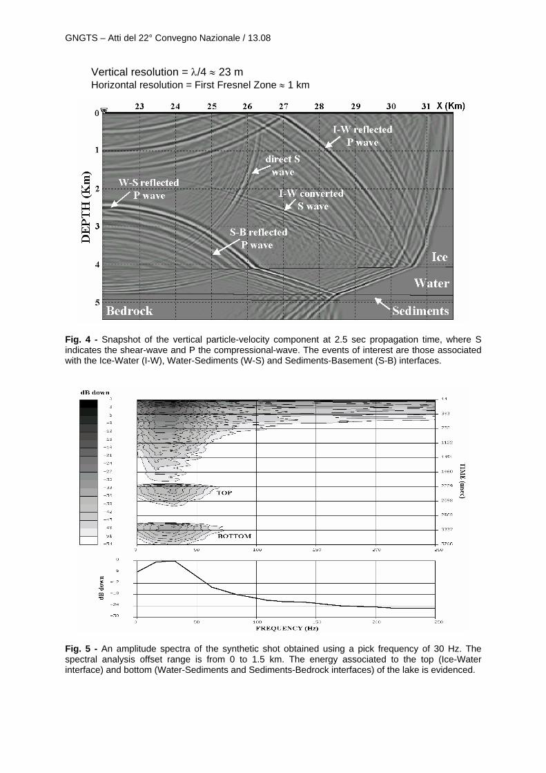
In the first step of the analysis we carried out an elastic simulation of a single shot in the synthetic model, at a centre of the lake area (Fig. 3), which provided useful information (frequency of the source and Amplitude Versus Offset information) for the acquisition geometry design. For this task we adopted a full-wave modelling commercial package (Tesseral 2-D; Tesseral Technologies Inc.) and the elastic properties on Tab. 1. The array used is 10 km long and we tested pick frequencies in a range from 20 to 50 Hz. A snapshot of the wavefield at 2.5 sec propagation time is shown in Fig. 4. The vertical component of the particle velocity is shown, and we can see the reflected events related to the three interfaces of interest: the Ice-Water (I-W) interface, Water-Sediments (W-S) and Sediments-Basement (S-B) interfaces. The direct shear wave and the P-S converted wave at the I-W interface are also evident. The presence of this converted wave could be very useful, since it may give information on S velocities. There is also a phase inversion related to the reflected wave at the I-W interface, but it may be revealed only analysing the horizontal component of the particle velocity. A spectral analysis of the synthetic shot gather obtained using a pick frequency of 30 Hz (Fig. 5), shows that in correspondence of 30 Hz there is enough energy associated to the top (Ice-Water interface) and bottom (Water-Sediments and Sediments-Bedrock interfaces) of the lake. So, using a pick frequency of 30 Hz, the maximum theoretical resolution at the bottom of the lake is:
GNGTS – Atti del 22° Convegno Nazionale / 13.08
Vertical resolution = λ/4 ≈ 23 m Horizontal resolution = First Fresnel Zone ≈ 1 km
Fig. 4 - Snapshot of the vertical particle-velocity component at 2.5 sec propagation time, where S indicates the shear-wave and P the compressional-wave. The events of interest are those associated with the Ice-Water (I-W), Water-Sediments (W-S) and Sediments-Basement (S-B) interfaces.
Fig. 5 - An amplitude spectra of the synthetic shot obtained using a pick frequency of 30 Hz. The spectral analysis offset range is from 0 to 1.5 km. The energy associated to the top (Ice-Water interface) and bottom (Water-Sediments and Sediments-Bedrock interfaces) of the lake is evidenced.
GNGTS – Atti del 22° Convegno Nazionale / 13.08
Since RSS seismic investigations on Vostok lake (Masolov et al., 1999) estimated for the sediment thickness a range from tens of meters to 350 m, a pick frequency of 30 Hz should enable to characterise the thin layer of sediments. Higher pick frequencies imply a greater absorption of energy in the ice layers, particularly in the firn layer, with a consequent weakening of the useful signal. On the other hand, lower frequencies compromises the resolution in depth.
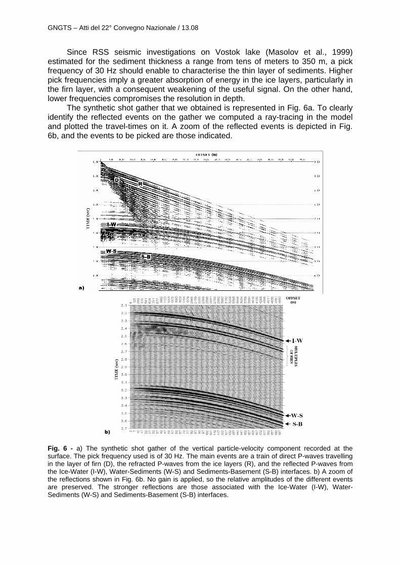
The synthetic shot gather that we obtained is represented in Fig. 6a. To clearly identify the reflected events on the gather we computed a ray-tracing in the model and plotted the travel-times on it. A zoom of the reflected events is depicted in Fig. 6b, and the events to be picked are those indicated.
Fig. 6 - a) The synthetic shot gather of the vertical particle-velocity component recorded at the surface. The pick frequency used is of 30 Hz. The main events are a train of direct P-waves travelling in the layer of firn (D), the refracted P-waves from the ice layers (R), and the reflected P-waves from the Ice-Water (I-W), Water-Sediments (W-S) and Sediments-Basement (S-B) interfaces. b) A zoom of the reflections shown in Fig. 6b. No gain is applied, so the relative amplitudes of the different events are preserved. The stronger reflections are those associated with the Ice-Water (I-W), Water-Sediments (W-S) and Sediments-Basement (S-B) interfaces.

GNGTS – Atti del 22° Convegno Nazionale / 13.08
The identification of the correct reflected events on a real shot gather will not be a simple task, because of the presence of a lot of multiples due to the firn layer (see Fig. 6b). As Carcione and Gei (2003) showed in their work, the reflection coefficients of the top (I-W interface) and bottom (W-S and S-B interfaces) show distinct characteristics, which allow their identification from real seismic records using AVA methods. However, to do that, it will be indispensable a processing aimed to the removal of the multiples. In fact, it can happen that the first multiple is overlapped to the S-B reflection event, and the case showed in Fig. 6 is an example. A τ-p transform, slant stack or plane-wave decomposition can be successfully used for this purpose.
THE TOMOGRAPHIC MODELLING
The analysis scheme that we adopted is the following:
1. On the first step we simulated an hypothetical seismic acquisition, performing a ray-tracing in the model and computing the travel-times of the reflected arrivals.
2. In the second step we carried out a travel-time tomographic inversion of the reflected arrivals using CAT-3D. Only the last three layers are analysed. All the other layers are fixed.
3. Finally, in the third step we compared the obtained inverse model with the initial synthetic model.
We adopted an acquisition pattern composed by two arrays of geophones, the
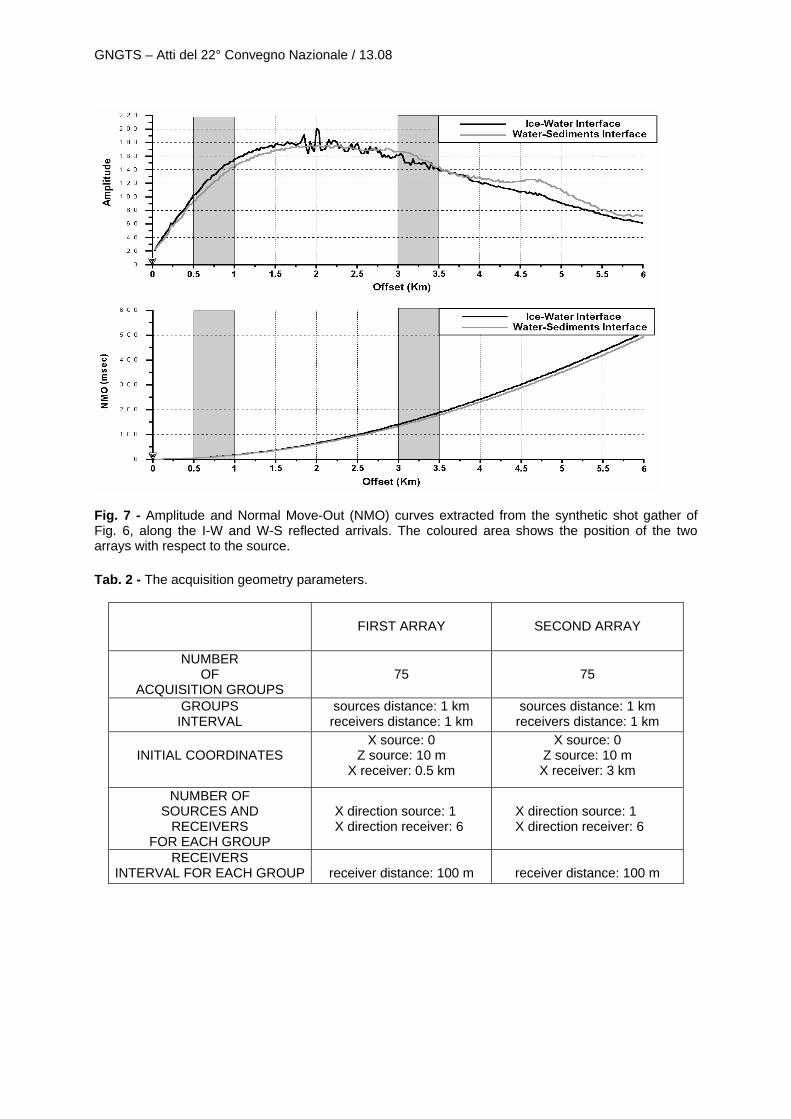
first placed near to the source and the second far from the source. In this way we have both small and high offsets, necessary to obtain a good resolution both in velocity and depth. The distances of the two arrays from the source is a compromise between the Amplitude curve and the Normal Move-Out (NMO) curve of the reflected arrivals. In Fig. 7 are plotted the Amplitude values and NMO values extracted from the synthetic shot gather shown in Fig. 6a, along the I-W and W-S reflected events.
Analysing the curves, we notice that the Amplitude is too low for offsets lower than 500 m, while reaches the maximum in the range from 1.5 km to 3.5 km. Moreover, we need a small Move-Out for the first array, and a large Move-Out for the second. Therefore, we chose a distance of 500 m for the first array, and a distance of 3.5 km for the second. The coloured area depicted in Fig. 7 indicates the position of the two arrays with respect to the source. The acquisition geometry parameters are resumed on Tab. 2. In Fig. 8 the acquisition procedure is described: the number of sources used is 75, one every km, and in each shift we translated together both the source and the two arrays. This acquisition geometry fulfils the main goal of this work: to limit the required budget and, because of the remarkable technical and operative problems on the Antarctic plateau, to reduce the acquisition equipment at minimum. Using this acquisition geometry, the fold at the bottom of the lake is constant and about of 6-8 rays/km. It is rather low, but high enough to faithfully recover the geometry of the lake.
GNGTS – Atti del 22° Convegno Nazionale / 13.08
Fig. 7 - Amplitude and Normal Move-Out (NMO) curves extracted from the synthetic shot gather of Fig. 6, along the I-W and W-S reflected arrivals. The coloured area shows the position of the two arrays with respect to the source. Tab. 2 - The acquisition geometry parameters.
FIRST ARRAY
SECOND ARRAY
NUMBER OF
ACQUISITION GROUPS
75
75
GROUPS INTERVAL
sources distance: 1 km receivers distance: 1 km
sources distance: 1 km receivers distance: 1 km
INITIAL COORDINATES
X source: 0 Z source: 10 m
X receiver: 0.5 km
X source: 0 Z source: 10 m X receiver: 3 km
NUMBER OF SOURCES AND
RECEIVERS FOR EACH GROUP
X direction source: 1 X direction receiver: 6
X direction source: 1 X direction receiver: 6
RECEIVERS
INTERVAL FOR EACH GROUP
receiver distance: 100 m
receiver distance: 100 m
GNGTS – Atti del 22° Convegno Nazionale / 13.08
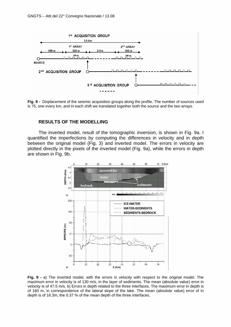
Fig. 8 - Displacement of the seismic acquisition groups along the profile. The number of sources used is 75, one every km, and in each shift we translated together both the source and the two arrays.
RESULTS OF THE MODELLING The inverted model, result of the tomographic inversion, is shown in Fig. 9a. I
quantified the imperfections by computing the differences in velocity and in depth between the original model (Fig. 3) and inverted model. The errors in velocity are plotted directly in the pixels of the inverted model (Fig. 9a), while the errors in depth are shown in Fig. 9b.
Fig. 9 - a) The inverted model, with the errors in velocity with respect to the original model. The maximum error in velocity is of 130 m/s, in the layer of sediments. The mean (absolute value) error in velocity is of 47.5 m/s. b) Errors in depth related to the three interfaces. The maximum error in depth is of 160 m, in correspondence of the lateral slope of the lake. The mean (absolute value) error of in depth is of 16.3m, the 0.37 % of the mean depth of the three interfaces.
GNGTS – Atti del 22° Convegno Nazionale / 13.08
The larger imperfections are in correspondence of the bottom of the lake: we obtained low velocity errors in the accreted ice layer and in the water layer, and high errors in the layer of sediments. This is due principally to the fact that the layer of sediments is too thinner than the other two. Moreover, the presence of meaningful velocity inversions (high velocity in the ice, low in the water layer and intermediate in the sedimentary package) causes large diversions of the rays crossing through the interfaces, and so high errors in the deeper layers. The maximum error in velocity is of 130 m/s in correspondence of the step, in the layer of sediments, while the maximum (but isolated) error in depth is of 160 m, in correspondence of the lateral slope of the lake. However, we have a mean (absolute value) error of 47.5 m/s in velocity, and of 16.3m in depth, the 0.37% of the mean depth of the three interfaces. Considering the large depth of the lake, this result is very good.
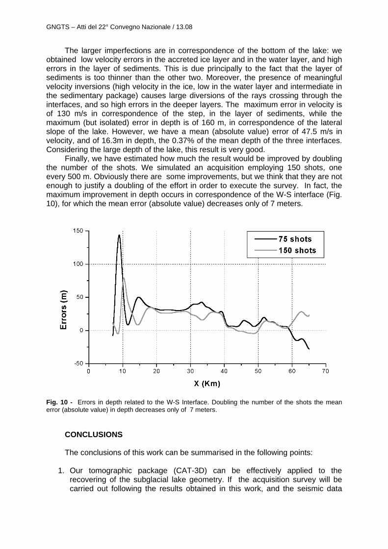
Finally, we have estimated how much the result would be improved by doubling the number of the shots. We simulated an acquisition employing 150 shots, one every 500 m. Obviously there are some improvements, but we think that they are not enough to justify a doubling of the effort in order to execute the survey. In fact, the maximum improvement in depth occurs in correspondence of the W-S interface (Fig. 10), for which the mean error (absolute value) decreases only of 7 meters.
Fig. 10 - Errors in depth related to the W-S Interface. Doubling the number of the shots the mean error (absolute value) in depth decreases only of 7 meters.
CONCLUSIONS
The conclusions of this work can be summarised in the following points:
1. Our tomographic package (CAT-3D) can be effectively applied to the recovering of the subglacial lake geometry. If the acquisition survey will be carried out following the results obtained in this work, and the seismic data
GNGTS – Atti del 22° Convegno Nazionale / 13.08
interpreted correctly, both the shape of the lake and the thickness of the sedimentary layer can be recovered with a good precision.
2. Since a future expedition will imply the solution of remarkable technical and operative problems, in order to verify the results of this work and to avoid a waste of resources, a preliminary instrumental test in Antarctica is necessary. This seismic acquisition test phase was successfully conducted in December 2003 (PEA 2003-2004). The designated test area was a zone close to the Dome C base, that represents a site of interest for the prospecting of subglacial lakes. The entire seismic acquisition system, developed and ad hoc built by the OGS, in cooperation with the Solgeo S.r.l., is designed to work in extreme climatic condition (temperature until -60°C). It is composed of five independent remote acquisition units with three channels each, a trigger unit and one exploder. The source used in the test survey was the explosive charge. During the tests it was verified the correct operation of the recording system and the acquisition parameters computed by the theoretical modelling. Besides all these technical considerations, another crucial problem in applying such seismic methods to ice is the coupling of sources and receivers with the surface. In fact, in proximity of the surface the density of firn is very low, and attenuates considerably the seismic energy in both ways when sources and receivers are placed at the ice surface. Therefore, to minimise this effect, it was also tested the quality of the obtainable data using different types of sources and depth holes.
3. The execution of a seismic survey will be eventually proposed on the basis of the results of the preliminary test. The analysis of the data acquired during the test is still in progress.
Acknowledgements. This work was presented at the XXII GNGTS Conference. The author would like to thank all the staff of the REDS group at OGS, and the OGS seismic crew for their contribution.
REFERENCES Carcione J. M. and Gei D.; 2003: Seismic modelling study of a subglacial lake. Geophysical
Prospecting, 51, 501-515. Kapitsa A. P., Ridley J. K., Robin G. de Q., Siegert M. J. e Zotikov I. A.; 1996: A large deep freshwater
lake beneath the ice of central East Antarctica. Nature, 381, 684-686. Masolov V. N., Kudryavtzev G. A., Sheremetiev A. N., Popkov A. M., Popov S. V., Lukin V. V.,
Grikurov G. E. e Leitchenkov G. L.; 1999: Earth science studies in the Lake Vostok region: existing data and proposals for future research. SCAR International Workshop Report on Subglacial Lake Exploration, Cambridge – England (2 vol.).
Picotti S.; 2003. Tomografia sismica del lago di Vostok. Proceedings of the XXII GNGTS Conference, Rome, Italy, 411-423.
Siegert M. J.; 2000. Antarctic subglacial lakes. Earth Science Reviews, 50, 29-50. Siegert M. J., Dowdeswell J. A., Gorman M.R. and McIntyre N. F.; 1996. An inventory of Antarctic
subglacial lakes. Antarctic Science, 8 (3), 281-286. Vesnaver A., Böhm G., Madrussani G., Petersen S. e Rossi G.; 1999: Tomographic imaging by
reflected and refracted arrivals at the North Sea. Geophysics, 64, 1852-1862.