seismic behavior of the slotted web (sw) connection on the
TRANSCRIPT

Seismic Behavior of the Slotted Web (SW) Connection
on the Iranian I-Shape Profiles Through Experimental
Studies
on the Iranian I-Shape Profiles Through Experimental
Studies
M. Gh. Vetr Assistant Prof, International Institute of Earthquake Engineering and Seismology(IIEES),Iran.
M. Miri Assistant Prof, Dept, of Civil Engineering, University of Sistan and Baluchestan , Iran.
F. Ghaffari M.Sc Student, Dept, of Civil Engineering, Islamic Azad University, Zahedan, Iran.
SUMMARY:
Shear force present in beam flanges and lateral torsional buckling are the main causes of weld fracture in the
mentioned connections. Research communities consider slotted web connection with its evaluated suitable
behavior for W-Sec profiles, as one of the connections that rectify many connection weaknesses, and
recommended. In this article, the seismic behavior of this connection on IPE cross-sections is investigated
considering analytical methods and experimental testing of effective factors in design. Considering design
measures, results show no strength reduction in this part compared to its non-slotted counterpart, and indicate
lower strain gradients in beam flange welds. Suitable ductility at this connection show this connection stands in
special moment connection class.
Keywords: Slotted web connection, lateral torsional buckling, seismic behavior, ductility
1. INSTRUCTIONS
Observations after the Northridge earthquake (1994) showed that shear forces present in beam flanges
were the main cause of brittle fracture in beam flange welding point regions. Existence of this force
leads to a non-uniform distribution of stress and strain during welding, and triaxial stress while welding beam flanges to columns. This issue arises while due to small width of the flange, existent
Shear force in beam flange was not considered in the design process.
Prior to the Northridge earthquake, slotted web connections, by improving many weaknesses present
in moment connections were introduced by Seismic Structural Design Associates (SSDA), and been
classified as a special moment connection in the American Institute of Steel Construction (AISC),
managed to qualify for the Federal Emergency Management Agency (FEMA) regulations. Experimental testing of this connection on a number of W-Sec profiles shows that it behaves suitably
toward cyclic loads.
In Slotted web connections, the separation of the beam flange from the beam web results in the
separation of flange force from the beam web, which leads to the elimination of shear force in beam
flanges and results in a more uniform distribution of stress and strain within the flange weld and
eliminates lateral torsional buckling along the beam length. Considering that the main purpose of connections is separating the plastic hinge from the connection joint, thus slotted web connection is
highly capable of distancing plastic hinges from the column face.
Considering the novel idea of slotted web connections in steel structures, the pivotal objective of this
research surrounds identifying the seismic behavior of this connection on semi-wide beam cross-
sections. In this study, ductility of slotted web connection is studied in two states without stiffener and with vertical flange stiffener, and factors concerning in this connection including strain distribution
along the weld, plastic hinge transfer method inside the beam and beam buckling were examined
compared to direct connection to the column (without slot).

1.2. Special Moment Frame Based on AISC Regulations
Based on AISC regulations, connections fulfilling the following requirements are considered special
moment frames (American Institute of Steel Construction, INC., 2010): 1. Capability of reaching relative ductility equivalent to 0.04 radians for beam to column connection
rotation.
2. Connection moment resistance on 0.04 radian rotating at column face a maximum 20 percent lower relative to nominal plastic moment.
And the required shear strength of the connection under quake loads is evaluated using relation 1.1:
(1.1)
Where Ry is coefficient of yield stress, Mp is the nominal plastic moment, Lh is the distance between
the plastic hinge goint on the beam’s span. In order to achieve the aforementioned conditions, different
connections should be examined in terms of stability and ductility by means of cyclic loading according to present procedures and valid regulations (American Institute of Steel Construction, INC.,
2010). Next, we will be discussing a new type of special moment connection.
2. SLOTTED WEB CONNECTIONS
The geometry of this connection presented in Fig. 2.1. consists of two horizontal slots ending to a hole at near the connection - which separates the beam flange from the beam web – and a shear plate which
is welded to the column along with the beam web. An original and reputed slotted connection
introduced in US regulations is in accordance to this model (ICC Evaluation Service, INC, 2002).
Figure 2.1. Slotted web connection
(Richard, Allen & Partridge, 1997 b; American Institute of Steel Construction, INC., 2010)
The basis of designing this connection is the moment diagram (based on ATC-24) demonstrated in
Fig. 2.2. which a plastic hinge starts from the beam flange and continues to the end of the slot, and the
beam web yield within the gap between the end of the slot and the plastic shear plate. By writing the
balance relation for Sec A-A and Sec B-B, lengths of the plastic hinge and slot are obtained (Tawil et al., 1997)
Figure 2.2. Moment diagram based on ATC-24 (Richard, Allen & Partridge, 1997 b)

Analytical study of slotted web connections indicate that undesirable ductility is due to rapid buckling
of beam flanges, and the resistance decline of this connection compared to its non-slotted counterpart.
Thus, in order to improve connection behavior and prevent rapid buckling of flanges, it is suitable to
utilize vertical flange stiffeners within the distance between the column face and end of the shear plate. The design of slotted web connection accompanied by vertical stiffeners is demonstrated in
Fig. 2.3.
Figure 2.3. Slotted web connection accompanied by vertical stiffeners
3. NUMERICAL STUDIES
This article, considering a model of slotted web connections on semi-wide profiles, attempts to study
its behavior in two states – with and without stiffener on the flange. All models were designed and
cyclic loaded according to AISC regulations. Sample configurations are presented in Fig. 3.1.
Steel specifications are based on experimental steel tension tests. The Steel stress-strain curve
(Fig. 3.2.) in the finite element method is considered three-line isotropic.
Figure 3.1. Sample configurations
Figure 3.2. Steel stress-strain curve

The beam employed in studied samples was a semi-wide IPE27 profile and loaded within one meter of
the column face. In addition, in order to prevent beam lateral displacement, a lateral bracing was
employed. Sample specifications and connection methods according to Fig. 3.1. are given in table 3.1.
Table 3.1. Sample Details
Doubler
Plate
(mm)
Lb
(cm)
LL
(cm)
H
(cm)
Steel
grade
Cross-
section Element Connection method Sample
2 PL 6
130 100 -------- ST37 IPE27 Beam Slotted Web SW1
------- ------- 100 ST37 IPB24 Column
2 PL 6
130 100 -------- ST37 IPE27 Beam Slotted Web with flange
stiffner SW2
------- ------- 100 ST37 IPB24 Column
Similar to the two previous samples for comparison in section (1-3) Beam with out Slotted
Web WUF
The loading record was selected according to the recommended standard by SAC regulations. This record, which is two-sided cyclic multiplier, was applied on the models using displacement control
method and based on the overall beam-rotating angle relative to the column. A sample of this cyclic
loading is given in Fig. 3.3.
Figure 3.3. Load history
Examining model finite elements was carried out using ANSYS software. 3D elements were employed for connection modeling, and Solid45 elements and suitable Hex meshes were utilized for meshing.
Fig. 3.4. depicts a sample meshed connection.
Figure 3.4. Numerical model shape in mesh mode with and without a vertical flange stiffener

Plastic hinge position inside the beam and the manner of beam flange buckling on both sides of the
slotted sample is demonstrated in Fig. 3.5. It is evident that flange hardness near the connections due
to added stiffeners prevents rapid buckling of beam flanges and improves connection ductility.
Utilizing stiffeners, existing heavy strain in flanges that lead to flange buckling can be controlled and reduced. Strain distribution chart along the length of the beam is depicted in Fig. 3.6. for two slotted
samples. In slotted web connections, separation of the web and flange leads to their independent
buckling and prevents lateral torsional buckling in the beam.
The Hysteresis graph for two slotted samples is demonstrated in Fig. 3.7. As specified in both graphs,
in the slotted non-stiffener connection, the sample has experienced force reduction in 0.03rad rotation due to rapid buckling in flanges. The maximum force is around 17 tons and reaches 20.5 tons in non-
stiffener and stiffener models respectively.
(a) (b)
Figure 3.5. Distribution of von Mises stress in slotted web connection a) SW1, b) SW2
Figure 3.6. Strain distribution on the flange within the length of the beam
(a) (b)
Figure 3.7. Hysteresis behavior in slotted web connections a) SW1, b) SW2
3.1. Strain Gradient in Beam Flange Weld
In order to examine the effect of creating a slot on strain gradian reduction in beam flange welds, strain distribution and rupture index were calculated on the connection region of the beam flange
width. The comparison dealing with slotted web connection and non-slotted web connections is given
in table 3.1. Rupture index was calculated using the equation 3.1., and is normally compared between connections with specific displacements and required numerical convergence.
⁄
(
)
(3.1)
In this equation, , , and are strain equivalent to plastic rotation, yield strain, hydrostatic
pressure stress, and von Mises stress respectively.
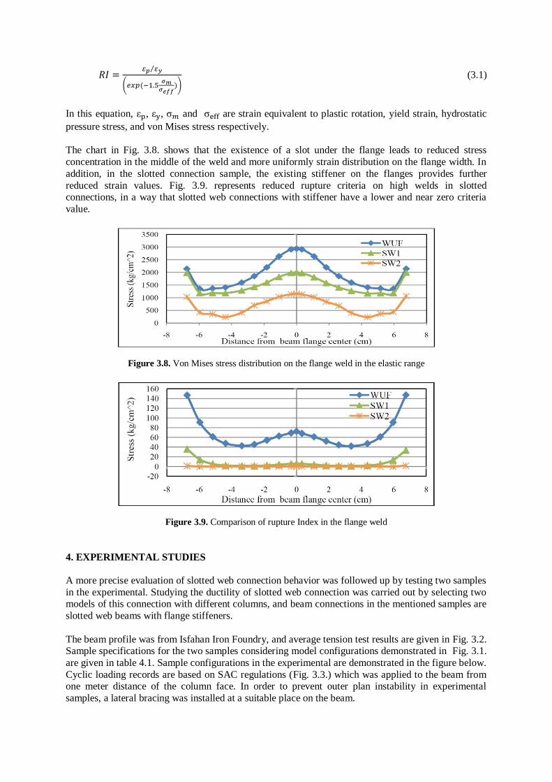
The chart in Fig. 3.8. shows that the existence of a slot under the flange leads to reduced stress
concentration in the middle of the weld and more uniformly strain distribution on the flange width. In
addition, in the slotted connection sample, the existing stiffener on the flanges provides further
reduced strain values. Fig. 3.9. represents reduced rupture criteria on high welds in slotted connections, in a way that slotted web connections with stiffener have a lower and near zero criteria
value.
Figure 3.8. Von Mises stress distribution on the flange weld in the elastic range
Figure 3.9. Comparison of rupture Index in the flange weld
4. EXPERIMENTAL STUDIES
A more precise evaluation of slotted web connection behavior was followed up by testing two samples
in the experimental. Studying the ductility of slotted web connection was carried out by selecting two models of this connection with different columns, and beam connections in the mentioned samples are
slotted web beams with flange stiffeners.
The beam profile was from Isfahan Iron Foundry, and average tension test results are given in Fig. 3.2. Sample specifications for the two samples considering model configurations demonstrated in Fig. 3.1.
are given in table 4.1. Sample configurations in the experimental are demonstrated in the figure below.
Cyclic loading records are based on SAC regulations (Fig. 3.3.) which was applied to the beam from one meter distance of the column face. In order to prevent outer plan instability in experimental
samples, a lateral bracing was installed at a suitable place on the beam.

Table 4.1. Experimental Sample Specifications
Doubler
Plate
(mm)
Sheet
dimensions
(cm)
Lb
(cm)
LL
(cm)
H
(cm)
Steel
grade
Cross-
section Element Sample
1 PL 8
W63x19x1
F63x22x1.5
130 100 ------- ST37 IPE27 Beam
Sample 1 ------- ------- 63 ST37
Plate
girder Column
----------- -------------- 130 100 ------- ST37 IPE27 Beam
Sample 2 ------- ------ 126 ST44 IPB24 Column
Figure 4.1. Experimental samples configurations
4.1. Test Results
In every loaded structure, changes occur that can be investigated from two aspects of surface shape changes and internal shape changes. These changes accompany different elastic, elastoplastic and
plastic stages after structure rupture. Experimental samples are coated with lime so that the state of
yeild and method of plastic hinge creation can be tentatively investigated.
By applying loads, lime is poured from the front of the flange stiffener and extended to the end of the
slot. In addition, the front part of the shear plate in the beam web enters the nonlinear range shown in Fig. 4.2.a. By continually adding more loads to the beam, the beam flanges gradually start to buckle
independent from the web connection’s buckling, and within this period, yeild continuous to progress
from the beam web to the end of the slot. After flange buckling, with the web connection entering the
nonlinear range, the web connection buckles and a wave appears in the length of the slot. The independent buckling of the flange and web connection eliminated the lateral torsional buckling mode
(Fig. 4.2.b).
(a) (b)
Figure 4.2. Yield of beam flange and web & beam flange buckling

Proceeding, after a 0.04rad rotation of the samples from the end of the slot in the rounded shape
location, due to intense increase in stress fractured in this region. At the end of the test, due to heavy
strain in the beam flanges, a rupture was observed in the middle of the slot after the stiffeners. Cyclic
loading results for the test samples are given in Fig. 4.3.
(a) Sample 1 (b) Sample 1
Figure 4.3. Cyclic behavior of experimental samples
The above graphs show that both samples have displayed desirable ductility and have endured an
overall 0.04rad rotation in more than 0.8Mp capacities, which indicates placement of slotted web
connections with vertical stiffeners in the special moment connections class. Considering utilization of Iranian semi-wide (IPE) profiles in design of this connection, its ductility and suitable seismic
behavior indicate the suitability of such profiles for this application.
Table 4.2. Final sample results
Panel zone rotation (rad)
Final rotation (rad)
Maximum force (KN)
Sample
0.0025 0.05 200 1
0.008 0.04 185 2
4.2. Strain Uniformness in the Flange Width (Strain Gauge)
Evaluation of uniform distribution in the width of beam flanges in experimental samples was carried
out by placing three strain gauges in a cross-section of the beam flange in one of the studied
experimental samples. The location of these three strain gauges is on the width of the flange in front of
the vertical stiffeners. Fig. 4.4. demonstrates the location of the strain gauges.
Considering that based on Hook’s law the elastic range of stress and strain, have a direct relation with
each other, therefore strain gauge values in the elastic range are considered acceptable. Strain gauge values in the elastic range are depicted in Fig. 4.5.
Figure 4.4. Strain gauge figure (sample 1)

Figure 4.5. Strain gauge results
According to the chart, strain distribution in the elastic range is identical on the flanges for all three
strain gauges. This indicates uniform stress distribution on the flange width. Entrance of the strain
gauges to the nonlinear started by the strain gauge no. two followed by strain gauges one and three.
5. CONCLUSION
1. Slotted web connection on semi-wide cross-sections with rotation endurance of more than 0.04rad
provide suitable ductility, and is considered a special moment connection according to AISC
regulations.
2. Utilizing vertical stiffeners on beam flanges in slotted web connections due to their special nature is
considered necessary to prevent early buckling of beam flanges and improving connection resistance
and ductility.
3. A connection with a weaker panel zone endures 0.01rad less rotation, and connection resistance has
observed an 8% decline. Existence of a weaker panel zone increase relative structural displacement and increase the Pi Delta effect.
4. Creating a slot in beam web eliminates shear force in beam flanges, and produces uniform distribution of strain in beam flanges weld. Independent buckling of flange and web in this connection
eliminates the lateral torsional buckling phenomenon.
REFERENCES
American Institute of Steel Construction, INC. (2010). Seismic Provisions for Structural Steel Buildings. AISC/ANSI 341-10.
Federal Emergency Management Agency (FEMA), (2000). Seismic Design Criteria for Steel Moment-Frame
Structures, FEMA 350 and 355D.
ICC Evaluation Service, INC; (2002), Slotted Web Beam-To-Column Steel Moment Frame Connection.
Division: 05-Metals, Section: 05120-Structural Steel, California.
Lee, Ch.H., Jeon, S.W., Kim, J.H., Uang, Ch.M., (2004) Seismic Performance of Reduced Section Steel Frame
Connections: Effects of Panel Zone Strength and Beam Web Connection Method, 13th World Conference
on Earthquake Engineering.
Mehrabian, A., Haldar, A., Moslehpour, S., (2006). Nonlinear Analysis of Steel Frames with Ductile
Connections. IJME - INTERTECH Conference. Session ENG 204-08.
Richard, R.M., Allen, C.J., and Partridge, C.E., (1997 a). Proprietary Slotted Beam Conections Designs. Journal of modern Steel Construction.
Richard, R.M., Allen, C.J., and Partridge, C.E., (1997 b). Steel Frame Stress Reduction Connection. United State
Patent Application Publication.
Richard, R.M., Allen, C.J., Partridge, C.E., (2001). Accumulated Seismic Connection Damage Based upon Full
Scale Low Cycle Fatigue Connection Tests. Journal of SEAOC Conventions.
Tawil, Sh.EL., Mikesell,T., Vidarsson, E., Kunnath, S. K., April (1998). Strength and Ductility of FR Welded-
Bolted Connections. SAC Steel Project. Report. SAC/BD98/01.