section 1.1 designing water distribution ... design date rev truckee meadows water authority 07/2011...
TRANSCRIPT
DRAWN DESIGN DATE REV TRUCKEE MEADOWS WATER AUTHORITY
07/2011 3rd ENGINEERING & CONSTRUCTION STANDARD
SECTION 1.1 – DESIGN STANDARDS 1-5
SECTION 1.1 DESIGNING WATER DISTRIBUTION FACILITIES
DESIGN STANDARDS 1.1.00 TOPIC INDEX
1.1.00 TOPIC INDEX 1.1.01 PURPOSE 1.1.02 GENERAL STATEMENT 1.1.03 WATER DISTRIBUTION SYSTEM PRESSURE ZONES 1.1.04 WATER DISTRIBUTION MAIN SIZES 1.1.05 HYDRAULIC ANALYSES 1.1.06 WATER MAIN LOCATION 1.1.07 FULL FRONTAGE EXTENSION 1.1.08 WATER MAIN JOINT DEFLECTION 1.1.09 DEPTH OF COVER 1.1.10 PIPE CASING 1.1.11 VALVES 1.1.12 CAPPING 1.1.13 THRUST AND ANCHOR BLOCKS 1.1.14 MECHANICALLY RESTRAINED JOINTS 1.1.15 SERVICE LATERALS 1.1.16 METERS 1.1.17 EXISTING/ABANDONED PRIVATE WELLS 1.1.18 BACKFLOW 1.1.19 FIRE HYDRANTS 1.1.20 WATER AND SEWER/STORM MAIN CROSSINGS AND CLEARANCE 1.1.21 NON-POTABLE WATER SYSTEMS 1.1.22 TAPS – 4 INCHES AND LARGER 1.1.23 LINE STOPS 1.1.24 EASEMENTS 1.1.25 WATER DESIGN SUBMITTAL 1.1.26 NEVADA DEPARTMENT OF TRANSPORTATION (NDOT) PERMITS
1.1.01 PURPOSE
This Standard contains the Truckee Meadows Water Authority's (Authority) standards for:
Designing Water Distribution Facilities (“Design Standards”) Construction Standards are covered in Sections 2 through 10 including Appendix 10.
DRAWN DESIGN DATE REV TRUCKEE MEADOWS WATER AUTHORITY
07/2011 3rd ENGINEERING & CONSTRUCTION STANDARD
SECTION 1.1 – DESIGN STANDARDS 1-6
1.1.02 GENERAL STATEMENT
The Authority’s water system is complex, consisting of two major gravity zones, approximately 100 pump zones and many isolated pressure regulated zones. Developers and Engineers are encouraged to contact the Authority at the earliest possible stage of development planning to gain an understanding of the Authority’s new business processes; operational constraints of the existing water system; the requirements of State water system regulations; facility and feeder main charges; and ultimately, the preliminary water system facility requirements for their projects. This understanding will assist the developer in obtaining adequate project financing and facilitate the project review and approval process. Water facilities design and hydraulic analyses shall consider both present and future demand scenarios. The Authority must be consulted for information regarding population projections and densities, per capita consumption, planned development, growth patterns and preliminary fire requirements (actual fire flow requirements are set by the Fire Department having jurisdiction in the area to be developed) to insure that water mains are adequately sized from the various sources of supply to every point in the system. Other design elements to be considered include: piping materials selection (water and soil corrosiveness considerations), the water main pressure requirements, water main location with reference to property lines and other utilities, sizing of service lines, location and size of line valves, fire hydrants, special valves, booster pumps, storage, water quality and looping/reliability issues. All hydraulic analyses and water system designs shall be prepared by, or under the direction of, a professional engineer licensed in the State of Nevada and are subject to review and approval of the Authority. The engineer is responsible for all aspects of the water facilities design and/or hydraulic analyses, except as specifically noted as Authority provided or furnished herein. All water facilities design and hydraulic analyses shall be performed in strict compliance with NAC 445A.65505 to 445A.6731, inclusive and/or Authority Standards. In case of conflicts, the most stringent standard shall apply. All Authority Standards shall be considered as minimum guidelines, and it is the engineer’s responsibility to confirm adequacy of same or provide an acceptable alternative as approved by the Authority. Nothing in Authority’s Design or Construction Standards shall be construed as superseding or negating any requirements of the NAC 445A.65505 to 445A.6731, inclusive; however, Authority’s Standards may in some instances be more stringent than the NAC requirements.
1.1.03 WATER DISTRIBUTION SYSTEM PRESSURE ZONES
1.1.03.01 In general, the Authority's pressure zones are designed to maintain a static pressure of 45 - 100 psi. Where new construction will create a new zone of pressure the maximum static water pressure allowed for any service in that new zone shall not exceed 100 psi.
1.1.03.02 In areas where a static pressure in excess of 80 psi is anticipated, individual
pressure regulating valves are required to be installed and maintained by the
DRAWN DESIGN DATE REV TRUCKEE MEADOWS WATER AUTHORITY
07/2011 3rd ENGINEERING & CONSTRUCTION STANDARD
SECTION 1.1 – DESIGN STANDARDS 1-7
owner/developer in accordance with the most current edition of the Uniform Plumbing Code (UPC). The Engineer will identify on the water plans the services requiring individual pressure regulating valves. Individual pressure regulating valves are also required for all services within pump system pressure zone and any area served by a central pressure regulating station.
1.1.03.03 New water system facilities and pressure zones and additions to the existing system
shall be designed to provide the following minimum water pressures under the various demand/flow conditions noted below:
A. Maximum Day 45 psi B. Peak Hour 40 psi C. Maximum Day + Fire 20 psi
Minimum water pressure requirements shall be considered at the ground elevation at the point of service connection, but should be based on the building pad elevation if it is greater than the elevation of the service connection point. Minimum water pressure requirements shall be strictly adhered to since additional pressure losses will occur through the meter, any backflow prevention devices, customer’s service line, customer’s internal plumbing and also from multi-floor elevation gain, if applicable.
1.1.04 WATER DISTRIBUTION MAIN SIZES
General Requirements A. All water mains shall be sized based on flow/demands and pressure requirements.
Distribution main sizes shall result in velocities less than eight (8) feet per second (fps) under peak hour demand conditions. Transmission or feeder main sizes shall result in velocities less than six (6) fps under peak hour demand conditions.
B. The minimum water main size to be installed in the Authority's system shall be
eight (8) inches in diameter (see exceptions below) unless otherwise approved by the Authority. Additionally, the Authority may establish minimum water main diameters based on other criteria.
C. Departures from the minimum requirements will be considered only in special
circumstances. Water mains in cul-de-sacs, internal streets within subdivisions, and other areas where water mains will not be extended in the future, may be six (6) inches in diameter, if that size water main meets the development's water demand requirements (including fire flows). Any departure from minimum requirements identified above shall be justified by a network hydraulic analysis.
DRAWN DESIGN DATE REV TRUCKEE MEADOWS WATER AUTHORITY
07/2011 3rd ENGINEERING & CONSTRUCTION STANDARD
SECTION 1.1 – DESIGN STANDARDS 1-8
1.1.04.01 Size - Fire Protection
A. When fire protection is to be provided, system design shall be such that fire flows and facilities are in accordance with the requirements of the Fire Department having jurisdiction. All systems must be designed to provide a minimum residual pressure of twenty (20) psi at all service connection points in the system during maximum day demand plus fire flow conditions.
B. Required fire flows and hydrant locations, both on-site and off-site, will be
identified on the Project water plans and approved by the Fire Department having jurisdiction.
C. The minimum water main size providing fire protection and serving fire
hydrants shall be six (6) inches in diameter. A maximum length of one-hundred fifty (150) feet of six (6) inch main serving a fire hydrant from a single source will be allowed. Upon review by the Authority private fire hydrants may require backflow prevention assemblies or other measures as determined by the Authority. Larger diameter mains will also be utilized, if necessary, to meet the required minimum fire flow while maintaining minimum residual pressure. A fire hydrant shall not be connected to a main that does not have sufficient fire flow capacity. Taps off Authority mains for private fire services shall include, at minimum, a double check detector assembly.
D. A maximum water velocity of eighteen (18) fps can be utilized when
designing new water facilities for maximum day plus fire flows and/or other temporary emergency conditions as long as residual pressure requirements are satisfied.
E. Fire suppression sprinkler systems shall be designed per the fire codes of
the Fire Department having jurisdiction. The design shall be based on sound engineering judgment considering the range of anticipated water pressures in the main as provided by the Authority. The design shall take into consideration the pressure losses associated with the fire flow demand through the lateral, backflow prevention assembly, etc.
F. Fire hydrants shall conform to the Standards of the Fire Department having
jurisdiction. G. All water plans must have the approval of the Fire Department having
jurisdiction PRIOR to submitting any plans to the Authority for water service application or approval.
DRAWN DESIGN DATE REV TRUCKEE MEADOWS WATER AUTHORITY
07/2011 3rd ENGINEERING & CONSTRUCTION STANDARD
SECTION 1.1 – DESIGN STANDARDS 1-9
1.1.04.02 Oversizing
The Authority may require the Developer to oversize some, or all, of the proposed water mains. Details regarding Authority oversizing are contained in Authority’s Rule 5.
1.1.05 HYDRAULIC ANALYSES
1.1.05.01 Submittal of Hydraulic Analyses for Review and Approval
A. Prior to performing the hydraulic analyses, contact the Authority and request information regarding supply/connection points for the project; HGLs of supply points; and unit demand data to be utilized for the project. This information should be furnished in writing by the Authority and must be included in the hydraulic analysis report.
B. The hydraulic analysis report may be submitted with the project design for
review. However, for larger projects such as a major subdivision or master planned development, submitting a hydraulic analysis report prior to water plan design and submission is required.
C. At least three (3) hard copies of the hydraulic analysis report must be
submitted. An electronic copy of the report and working computer model of the water facilities to serve the project must be submitted on CD. One copy of the report and the CD will be retained by the Authority. Listed below are general requirements and specific elements that must be addressed in the hydraulic analysis submittal. The Engineer is encouraged to contact the Authority for guidance in preparing the report.
1.1.05.02 General
A. The hydraulic analyses must be signed and sealed by a Professional Engineer licensed in the State of Nevada.
B. Provide the name, address, telephone and fax number of the developer and
developer's engineer on the report cover. C. Each page of the submittal must be numbered. D. Provide the name and version of software used for the hydraulic analyses.
The software utilized to develop the computer model and perform the hydraulic analyses must be compatible with Authority’s H20Net modeling software and AutoCAD to allow conversion and insertion of the engineer’s model into Authority’s model data base.
DRAWN DESIGN DATE REV TRUCKEE MEADOWS WATER AUTHORITY
07/2011 3rd ENGINEERING & CONSTRUCTION STANDARD
SECTION 1.1 – DESIGN STANDARDS 1-10
E. If the project involves Authority required oversizing, indicate so in the
report, and use the Authority-required pipeline diameter when modeling the project.
1.1.05.03 Project Description
A. Provide a written description of the type of project, location, and existing facilities. Include a site map with project boundaries.
B. Provide a grading plan which includes street and lot layouts. C. Provide development information including gross acreage, land use, number
of units, plan sheet with approved fire flow requirements and hydrant locations, development schedule, and identify construction phasing. Separate analyses will be required for each final map development phase.
D. Include a large-scale node map clearly delineating the pipeline alignments
and diameters, layout and names of streets/roadways in which the pipelines will be installed, the pipe and node numbers used in the analyses, and all fire hydrant locations.
E. The text and node maps shall use a minimum font size of ten (10).
1.1.05.04 Source HGL and Demand Calculations
A. Clearly show the source node, or nodes provided by the Authority and use the Authority-issued HGLs for that node(s) in the analyses. Enclose a copy of the letter sent by the Authority issuing these HGLs. Clearly indicate whether non-potable water will be utilized for irrigation demands.
B. Calculate demands using base demand and peaking factors provided by the
Authority for gpm/acre and/or gpm/residential unit based on lot size. Irrigation demands for common areas should be provided by a landscape architect and should identify proposed metering points, irrigation zones and zone demands. Show calculations in table format. All irrigation demands shall be shown separately and shall be separated into permanent and revegetation demands, if applicable. All demands are subject to review and approval of the Authority.
1.1.05.05 Input Data Tables
A. Provide input data tables for all pipes modeled. Pipe data tables shall include, at a minimum, pipe segment identified as shown on the node map,
DRAWN DESIGN DATE REV TRUCKEE MEADOWS WATER AUTHORITY
07/2011 3rd ENGINEERING & CONSTRUCTION STANDARD
SECTION 1.1 – DESIGN STANDARDS 1-11
beginning and ending nodes, lengths in feet, diameters in inches, coefficient of friction, and other pertinent information.
B. Provide input data tables for all nodes modeled. Junction node data tables
shall, at a minimum, include node identification as shown on the node map, elevation in feet for all nodes using the NAVD 88 datum, node demand in gpm, connecting pipes, and other pertinent information.
1.1.05.06 Analysis
A. Separate analyses for Average Day, Maximum Day, Maximum Day plus Fire Flow, and Peak Hour conditions are required for each phase of the development, as well as for the entire project. In the analyses for Maximum Day plus Fire Flow, the worst-case scenario must be considered.
B. Explain any assumptions made as part of conducting the analyses; provide
any comments that may ease and expedite the review of the analyses.
1.1.05.07 Output Data Tables
A. Output results for pipes shall include, at a minimum, flow rate in gpm, flow velocity in fps, head loss in feet, and other pertinent information for each pipe. A separate pipe report is required for each demand scenario analyzed.
B. Output results for nodes shall include, at a minimum, hydraulic grade in
feet, node pressure in psi, elevation, demand, and other pertinent information for each node. A separate node report is required for each demand scenario. Provide a separate hydrant node report with residual pressure at each hydrant for the required flow and the minimum system residual pressure in the system when flowing that hydrant.
C. Provide a summary table, for each phase of development, showing the
minimum and maximum residual pressures for each condition, and minimum and maximum static pressures.
1.1.05.08 Miscellaneous
A. The roughness factors to be used in the analyses for proposed piping should be as follows:
C= 120 for pipe 12-inch in diameter C= 130 for pipe 14-inch in diameter

DRAWN DESIGN DATE REV TRUCKEE MEADOWS WATER AUTHORITY
07/2011 3rd ENGINEERING & CONSTRUCTION STANDARD
SECTION 1.1 – DESIGN STANDARDS 1-12
For any other sizes or materials not covered by the above, or if the analysis includes portions of the existing system, the Engineer shall contact the Authority for guidance.
B. When identifying the fire flow available in a network hydraulic analysis use
the hydrant located at the development's weakest point, generally the highest point in the development and/or the last hydrant on a dead end main. A junction node should be placed at the appropriate location in the model to represent the fire hydrant.
C. The node elevations in the hydraulic analyses shall be based on the project
grading plan and should reflect final street and building pad elevations. Node elevations should reflect the highest street or pad elevation in the vicinity of that node. If a final grading plan deviates significantly from the elevations used in the analyses, a revised analysis will be required.
1.1.06 WATER MAIN LOCATION
1.1.06.01 Main extensions should be located within a dedicated right-of-way. If a dedicated right-of-way is not available, the main may be located elsewhere upon Authority approval and upon the granting of an easement to the Authority. The easement shall be twenty (20) feet or greater in width and shall consist of a fifteen (15) foot wide all-weather road surface to provide vehicle and equipment access for maintenance purposes. If road grade exceeds eight percent, the road surface shall be paved. In no case should road grades exceed ten percent unless specifically approved by the Authority. Water lines shall be located five (5) feet from the property line or easement edge or as specified by the Authority for the entire water main length. Other utilities may be located in the same easement per Section 1.1.06.04 only as approved by the Authority. Water mains may be constructed under structures, or in or under bodies of water only if approved by the Health Authority.
1.1.06.02 Where street curbs are present, water mains will be designed to the extent possible
with center of pipe horizontal alignment located seven (7) feet from the back of curb. In areas without curb and gutter, the water mains will be designed to the extent with center of pipe horizontal alignment located within in the paved area and seven (7) feet from the edge of asphalt unless established otherwise by the Authority.
1.1.06.03 Tracer Wire and/or locator tape will be required in accordance with Authority
Standards directly over all water mains, over all service laterals not installed at ninety (90) degrees to the water main horizontal alignment, all service laterals greater than fifty (50) in length, and over all water facilities not installed in common trench with gas, or where directed by the Authority.
DRAWN DESIGN DATE REV TRUCKEE MEADOWS WATER AUTHORITY
07/2011 3rd ENGINEERING & CONSTRUCTION STANDARD
SECTION 1.1 – DESIGN STANDARDS 1-13
1.1.06.04 If the water main design does not call for a common trench water main and gas
main installation, and gas is to be located within a separate trench, then the gas main must be located no less than three (3) feet from the water main trench wall. Water main designs shall comply with the separation requirements conveyed in Section 1.1.20 and 1.1.21. Designs shall incorporate a separation of ten (10) feet horizontally (outside to outside) from any non-potable water line (reclaimed) or sewer line (sanitary or storm), and eighteen (18) inches vertically above any non-potable water line or sewer line, or as otherwise provided for in Section 1.1.20 and 1.1.21. Location of other utilities in the easements should be coordinated with the Authority on an individual basis.
1.1.06.05 If a vertical clearance of eighteen (18) inches between the water line that crosses
over a non-potable water line or sanitary or storm sewer line cannot be maintained, then the design must comply with the criteria for water/non-potable water line or sewer main crossings in Section 1.1.20 and 1.1.21 must be complied with.
1.1.06.06 Dead-end mains shall be minimized by looping mains whenever practical or where
required by the Authority and/or the Health Authority. Preliminary design and layout of subdivision streets and lots should contribute to elimination of dead-end mains. The maximum length of a dead-end main shall be approximately 800 feet. All dead-end mains shall be terminated with a flush valve assembly.
1.1.06.07 Mains installed in a cul-de-sac shall run the full street length ending approximately
fifteen (15) feet from the property's front edge at the end of the cul-de-sac, or five (5) feet past the last service as designated on the plans, unless they are looped. Mains installed in a cul-de-sac that is greater than eight hundred (800) feet in length shall be looped where practical.
1.1.06.08 Temporary dead-ended mains that will be extended with subsequent phases of
development shall be stubbed at least ten (10) feet beyond the edge of pavement and shall be terminated with a flush valve assembly.
1.1.07 FULL FRONTAGE EXTENSION
At the Authority's discretion, the developer may be required to install the water main along the entire length of at least one property line frontage of the property to be developed whenever future line extension is possible. The property line frontage is that portion of the property along the public right-of-way. If a parcel to be developed has more than one property line frontage, the Authority may require a water line to be installed along the other frontage(s). The minimum pipe diameter required in the frontage street shall be in accordance with Section 1.1.04, or as required by the Authority.
DRAWN DESIGN DATE REV TRUCKEE MEADOWS WATER AUTHORITY
07/2011 3rd ENGINEERING & CONSTRUCTION STANDARD
SECTION 1.1 – DESIGN STANDARDS 1-14
1.1.08 WATER MAIN JOINT DEFLECTION
The maximum allowable water main joint deflection for C900 PVC pipe with bell and spigot push-on joints and ductile iron (DI) pipe with bell and spigot push-on joints or mechanical joints shall be as described below. For changes in direction which exceed the maximum allowable described below, fittings shall be installed.
1.1.08.01 C900 PVC
A. C900 PVC pipe shall only be deflected at joints. Bending of PVC pipe is not permitted by the Authority. The maximum allowable joint deflection at C900 PVC pipe bell and spigot push-on joints shall be one (1) degree, which equates to a maximum pipe end offset of approximately four (4) inches for a nominal twenty (20) foot pipe length, and a minimum radius of curvature produced by a succession of joints of 1,150 feet.
B. Where C900 PVC pipe is installed into and out of push-on joint ductile iron
fittings, a maximum deflection of four (4) degrees is allowed at each fitting joint.
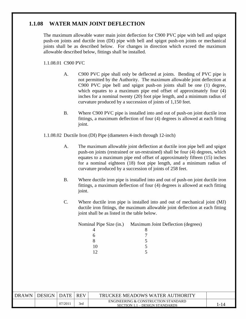
1.1.08.02 Ductile Iron (DI) Pipe (diameters 4-inch through 12-inch)
A. The maximum allowable joint deflection at ductile iron pipe bell and spigot push-on joints (restrained or un-restrained) shall be four (4) degrees, which equates to a maximum pipe end offset of approximately fifteen (15) inches for a nominal eighteen (18) foot pipe length, and a minimum radius of curvature produced by a succession of joints of 258 feet.
B. Where ductile iron pipe is installed into and out of push-on joint ductile iron
fittings, a maximum deflection of four (4) degrees is allowed at each fitting joint.
C. Where ductile iron pipe is installed into and out of mechanical joint (MJ)
ductile iron fittings, the maximum allowable joint deflection at each fitting joint shall be as listed in the table below.
Nominal Pipe Size (in.) Maximum Joint Deflection (degrees) 4 8 6 7 8 5 10 5 12 5
DRAWN DESIGN DATE REV TRUCKEE MEADOWS WATER AUTHORITY
07/2011 3rd ENGINEERING & CONSTRUCTION STANDARD
SECTION 1.1 – DESIGN STANDARDS 1-15
1.1.09 DEPTH OF COVER
Designs shall call for a minimum depth of cover to be maintained for all pipe unless otherwise specified and approved by the Authority. During construction, vehicle and equipment traffic over the water mains may be restricted until at least twenty-four (24) inches of cover is obtained and such minimum cover is deemed adequate by the developer’s engineer for the pipe material and trench conditions for H-20 loads under non-pressurized conditions. A temporary twenty-four (24) inch minimum depth of cover must be maintained during construction. Unless otherwise approved by the Authority, the final depth of cover shall not exceed sixty (60) inches, but in no case shall be less than thirty-six (36) inches above top of pipe at final grade.
1.1.09.01 Right-of-Way Without an Established Street Grade
The installation of mains in locations where there is not an established final grade shall only be allowed with the prior approval of and at the sole discretion of the Authority. Design drawings shall convey a sixty (60) inch minimum depth of cover over any pipe where there is not an established street grade. The Engineer shall consider possible, and probable, future development and grading to achieve the minimum depth of cover as described in Section 1.1.09.02 following development of the area. Per Rule 5, the Authority will require the developer to deposit cash or post a bond for the Authority’s estimated cost of relocation of facilities installed in areas not having an established final grade.
1.1.09.02 Right-of-Way With an Established Street Grade
Where there is an established street grade, the minimum depth of cover of thirty-six (36) inches from final grade to top of pipe shall be conveyed and included in the design drawings.
1.1.09.03 NDOT Right-of-Way
Designs shall incorporate a forty-eight (48) inch minimum depth of cover to be maintained over all water mains located within NDOT Right-of-Way, or as specified in the NDOT permit.
1.1.10 PIPE CASING
1.1.10.01 Steel Casing Design drawings shall call for steel casings to be required on all pipe installed using jack and boring methods, where approved by the Authority and required to meet specific Railroad and/or NDOT requirements, to provide structural support, or as required under other special conditions. The pipe casing shall be designed to be
DRAWN DESIGN DATE REV TRUCKEE MEADOWS WATER AUTHORITY
07/2011 3rd ENGINEERING & CONSTRUCTION STANDARD
SECTION 1.1 – DESIGN STANDARDS 1-16
laid true to line and grade with no bends or changes in grade for the full casing length. The casing material used shall be a minimum of one-quarter (¼) inch thick steel (design calculations must be submitted by the developer's engineer) and conform to ASTM A283, Grade B, C, or D. All joints shall be welded. Interior joints shall be ground to a smooth finish. All welding shall be performed in accordance with AWWA C206, “Field Welding of Steel Water Pipe" and/or Authority’s welding standards. Coatings for steel casings are not required. The design drawings shall include the appropriate casing diameter based on the diameter of the carrier pipe and manufacturer’s recommendation based on Authority approved pipe spacers. Other casing materials may be utilized for applications other than boring when approved by the Authority.
1.1.10.02 Pipe Spacers
The design drawings shall include details conveying the pipe to be symmetrically supported about its centerline inside the casing at each joint end with an Authority approved polyethylene spacer, sized and designed per manufacturer recommendations.
1.1.10.03 Casing End Caps
The design shall include an Authority approved end seal for the water main casing.
1.1.10.04 Carrier Pipe
Carrier pipe within the casing shall be restrained joint ductile iron pipe.
1.1.11 VALVES
1.1.11.01 Valve Location Design drawings shall include valves to be placed on water mains to minimize inconvenience, degradation of fire protection and sanitary hazards during repairs. Valves shall be generally located as follows, unless otherwise approved by the Authority: A. At intervals to isolate no more than two (2) fire hydrants at any time. B. At minimum intervals of approximately five hundred (500) feet, preferably
at street intersections, in commercially zoned areas, and for residential off-site water mains. Valves for mains installed in areas of scattered development or locations where future development is not expected shall be installed at intervals/locations as shown on the approved drawings, but in no case shall valve spacing exceed one mile.
DRAWN DESIGN DATE REV TRUCKEE MEADOWS WATER AUTHORITY
07/2011 3rd ENGINEERING & CONSTRUCTION STANDARD
SECTION 1.1 – DESIGN STANDARDS 1-17
C. In residential areas, valves shall be provided at all main intersections and as
necessary to isolate a maximum of thirty (30) services (approximately 600 feet, but not to exceed 800 feet).
D. A maximum of five (5) valves will be required to isolate any location. E. Valves shall not be located in street gutters, valley gutters, or in driveways. F. A valve is required at the end of all temporarily dead-end mains. The valve
is to be located a minimum distance upstream of the temporary flush valve assembly, as determined by the developer’s engineer, to ensure safe removal of temporary flush valve assembly upon extension of water main and to minimize service disruption.
G. A shut off valve immediately adjacent to the water main shall be provided
for all service laterals greater than two (2) inches in diameter, and for all fire hydrant laterals.
H. A minimum of two valves shall be installed at all branch tees. A minimum
of three valves shall be installed at all crosses. The Authority may require additional valves depending upon the project design.
I. Valves installed to isolate one pressure zone from another, also known as
“normally closed valves”, shall be subject to review and approval of the Authority. If approved, normally closed valves shall be installed only with adequate flushing devices on each side of the valve prior to the next service connection. This provision does not relieve the developer’s or engineer’s responsibility for eliminating dead-ends whenever possible.
1.1.11.02 Gate Valves
A. Designs will provide for gate valves to be installed on all water mains up to,
and including, eighteen (18) inches in diameter. Gate valves may be used for larger water mains if adequate depth of cover can be maintained above the valve as approved by the Authority, or if they can be installed on their side with a bevel gear operator, or if otherwise required by the Authority. Separate six (6) inch bypass piping with an isolation valve may be required around gate valves larger than eighteen (18) inches in diameter.
B. Gate valves eighteen (18) inches in diameter and smaller shall be installed
in the vertical position with non-rising stems in all locations, except vaults, unless otherwise specified by the Authority.
DRAWN DESIGN DATE REV TRUCKEE MEADOWS WATER AUTHORITY
07/2011 3rd ENGINEERING & CONSTRUCTION STANDARD
SECTION 1.1 – DESIGN STANDARDS 1-18
C. All gate valves shall be supplied by Authority approved manufacturers, be resilient seat, and meet the requirements of AWWA C509, C515 and C550 and Authority’s Standards.
1.1.11.03 Butterfly Valves
Butterfly valves shall be approved for use only when system pressures exceed one hundred and fifty (150) psi. Butterfly valve make, model and installation details shall be specified by the Authority.
1.1.11.04 Valve stem extensions
Design drawings must call for valve stem extensions to be required within two (2) feet of finished grade where the distance from the top of the valve box to the top of the operating nut exceeds five (5) feet.
1.1.11.05 Valve Boxes
Adjustable valve boxes shall be included on design drawing for all buried valves. Valve boxes shall be installed in accordance with Authority’s Construction Standards.
1.1.11.06 Special Valves
A. Air relief and/or air vacuum relief valves must be installed on pipelines’
high points and changes in grade, depending on terrain and the potential for air entrapment or collapse due to vacuum. Air valves shall be sized and detailed by the design engineer and shall include above grade, screened riser vent pipes located within the PUE or right-of-way and protected by pipe bollards.
B. Pressure regulating valves (PRV) will be required where it is necessary to
reduce pressure to a maximum value as defined in Section 1.1.03. Central pressure regulating stations will be required as determined by the Authority. Individual pressure regulating valves will be required on individual service lines in a pressure zone served by a central pressure regulating station or a central pump station. Individual pressure regulating valves will be owned and maintained by the property owner.
C. Check valves are to be used where it is required that the water flow in one
direction only. Check valves shall be installed with isolation valves and a separate valved bypass line to facilitate maintenance or emergencies. A flushing device shall be installed on the checked side of the valve. Check valves shall be supplied by Authority approved manufacturers. Materials,
DRAWN DESIGN DATE REV TRUCKEE MEADOWS WATER AUTHORITY
07/2011 3rd ENGINEERING & CONSTRUCTION STANDARD
SECTION 1.1 – DESIGN STANDARDS 1-19
trim, seats, coating, lining and options shall be in accordance with Authority Standards.
D. Flush valve assemblies are required on all permanent dead-end pipe runs
and may be required at stub-out locations. Flush valves shall be sized to provide a minimum velocity of two and a half (2.5) feet per second (fps) in the main. Flush valve assemblies for these locations shall be installed in accordance with Authority’s Construction Standards.
E. Appropriately sized manual blow–off valves shall be installed at appropriate
locations at low points in water mains with diameters of 20 inches or more. Manual blow-off valves shall be installed in accordance with Authority’s Construction Standards for smaller diameter mains as required by the Authority. Blow-offs shall be sized to provide a minimum velocity of two and a half (2.5) feet per second (fps) in the main.
F. Backflow Prevention Device requirements are identified in Section 1.1.18. The openings of any vents in a valve must be located at least one foot (1’) above grade and the discharge pipe must be screened, elbowed to face down and protected from traffic. Screen must not be susceptible to damage by corrosion and must have a minimum of twenty-two (22) and not more than twenty-four (24) mesh per inch.
1.1.11.07 Valve Retirement
A. Any valved outlet installed prior to lot development, and subsequently not
required, or not proposed to be utilized to provide service, must be retired. B. For valve retirement, the following methods shall be utilized and the
following notes shall appear on the design drawing: RETIRED VALVES All valves to be retired shall be abandoned in the closed position, unless shown otherwise, by removing a minimum of the top twenty-four (24) inches of the valve box and then filling the bottom of the box with a minimum of eight (8) inches of sand or Type 2, Class B aggregate base, the remaining portion of the valve box shall be filled with concrete.
C. If the valve is to be retired in the closed position, the following note shall
also appear on the drawing: CUT AND CAP The lateral must be cut within three (3) feet of the abandoned valve, or as shown on plans, and capped. The Contractor shall cut the existing pipe where shown on the drawing and install a cap complete with
DRAWN DESIGN DATE REV TRUCKEE MEADOWS WATER AUTHORITY
07/2011 3rd ENGINEERING & CONSTRUCTION STANDARD
SECTION 1.1 – DESIGN STANDARDS 1-20
thrust block. Where a joint or coupling in the existing pipe is uncovered at the cut and cap locations, the installation of a plug may be permitted with Authority approval. A concrete thrust block shall be installed at all cap or plug locations in accordance Authority’s Construction Standards. If the valve to be retired has a flanged outlet, a blind flange may be installed in lieu of cutting and capping the pipe.
1.1.12 CAPPING
A cap or plug may be used as approved by the Authority. 1.1.13 THRUST AND ANCHOR BLOCKS
Thrust blocks are required at all caps, valves, reducers, tees, and fittings used to change the pipe direction, and shall be placed in accordance with Authority’s Construction Standards. Thrust blocks for each location shall be designed by the design engineer to account for allowable soil bearing capacity, main size, main pressure and change in direction. If the allowable soil bearing capacity is unknown, thrust block design shall be based on an assumed soil bearing capacity of two thousand (2,000) pounds per square foot (psf); however, the design engineer must verify soil conditions at the time of construction and make adjustments as required. Thrust block design shall provide suitable support under test pressure conditions (the greater of one hundred and fifty (150) pounds per square inch (psi) or two (2) times the working pressure of the main). Vertical and horizontal thrust blocks shall be made of concrete having a compressive strength of not less than three thousand (3,000) psi after twenty-eight (28) days. Bag concrete mix is not acceptable. A thrust block schedule shall be included on all water main design drawings, or the plans shall clearly state that the Authority’s thrust block schedule, or noted portions thereof, are suitable for the project. If uncompacted or unclassified backfill material is present; then mechanical restrained joints shall be required in addition to a thrust block.
1.1.14 MECHANICALLY RESTRAINED JOINTS
Mechanically restrained joints may be used with ductile iron pipe only, and only upon Authority approval, or as required by the Authority. The distance on either side of fittings where restrained joints are required should be clearly identified on drawings and calculations shall be submitted when required by the Authority. Restrained joints are required on all fittings at vertical offsets. The Authority may also require ductile iron pipe with restrained joints for pipelines installed across drainage ways or natural grades in excess of ten (10) percent. Unless approved by the Authority thrust blocks will be required with mechanically restrained joints. Restrained mechanical joint fittings shall be restrained using mechanical joint wedge action restraint glands manufactured by manufactures approved by the Authority. Methods and manufacturers used to mechanically restrain ductile iron pipe shall be approved by the Authority.
DRAWN DESIGN DATE REV TRUCKEE MEADOWS WATER AUTHORITY
07/2011 3rd ENGINEERING & CONSTRUCTION STANDARD
SECTION 1.1 – DESIGN STANDARDS 1-21
1.1.15 SERVICE LATERALS Service laterals shall be designed and sized to provide peak hour capacity without excessive pressure losses taking into account anticipated losses through the meter, setter and backflow prevention device. Service lateral sizes are subject to the review and approval of the Authority. Service lateral materials shall be furnished and installed in accordance with Authority Standards.
1.1.15.01 Location
A. All service laterals shall be installed in the public right-of-way or public
utility easement unless other provisions have been approved by the Authority.
B. The full service lateral length between a water main and water meter shall
be installed at ninety (90) degrees to the water main horizontal alignment unless otherwise approved by the Authority. If the water main configuration does not allow for a ninety (90) degree service lateral installation, tracer wire must be installed above the service lateral per Section 1.1.06.03.
C. For service laterals two (2) inches in diameter and smaller, service saddles
shall not be closer than twenty-four (24) inches from the end of the main or any pipe joint. For PVC and AC mains, service saddles shall be no closer than eighteen (18) inches to an adjacent service saddle when the service taps are on opposite sides of the main. For ductile iron, cast iron, and steel mains, service saddles shall be no closer than nine (9) inches to an adjacent service saddle when the service taps are on opposite sides of the main. For PVC and AC mains, service saddles shall be no closer than thirty-six (36) inches to adjacent service saddles when the service taps are located on the same side of the main. For ductile iron, cast iron, and steel mains, service saddles shall be no closer than eighteen (18) inches to adjacent service saddles when the service taps are located on the same side of the main.
D. The sewer and water laterals leading into the property shall be separated
horizontally by a minimum of four (4) feet, the sewer lateral must be a minimum of one (1) foot lower than the water lateral, and the laterals shall be located in separate trenches, per NAC 445A requirements (also see Section 1.1.20).
E. All service laterals shall be located a minimum of ten (10) feet from septic
tanks, and a minimum of twenty-five (25) feet from leach beds and/or seepage pits.
DRAWN DESIGN DATE REV TRUCKEE MEADOWS WATER AUTHORITY
07/2011 3rd ENGINEERING & CONSTRUCTION STANDARD
SECTION 1.1 – DESIGN STANDARDS 1-22
1.1.15.02 Lateral Installation A. Service saddles shall be furnished in accordance with the Authority's
approved materials list for the type of pipe used and installed per the manufacturer’s instructions.
B. Corporation stops shall be male iron pipe thread by compression or flared
connection. A corporation stop shall be installed with the service saddle at the water main for all service laterals two (2) inches and smaller.
C. Minimum lateral diameters for meter sizes up to four (4) inches shall be as
follows:
Required Meter Size (in.) Minimum Lateral Size (in.) ¾ 1 1 1-1/4 1-1/2 1-1/2 2 2 4 4
D. All service laterals four (4) inches and larger will require a tee and gate
valve at the source main and the lateral shall be a material approved by, and in accordance with, the Authority’s Standards.
E. Service laterals will not be allowed or installed for future lots unless
otherwise approved by the Authority.
1.1.15.03 Lateral Removal A. When retiring existing water service assemblies sized two (2) inches and
smaller, the following note shall appear on the drawing:
RETIREMENT OF EXISTING SERVICE LATERALS (2 - inch) The Contractor shall notify the Authority two (2) full business days prior to the requested removal time to allow the Authority to take the final meter reading and to notify the Authority’s Inspector of the impending work. The Contractor may begin removal procedures for the affected service as follows: Existing service laterals to be retired from existing water mains shall have the corporation stops turned off at the main, a minimum of twelve (12) inches of the lateral cut out near the corporation stops and a brass cap/plug installed on the corporation stop. If the corporation stop is damaged beyond repair or pulled from the existing water main, the
DRAWN DESIGN DATE REV TRUCKEE MEADOWS WATER AUTHORITY
07/2011 3rd ENGINEERING & CONSTRUCTION STANDARD
SECTION 1.1 – DESIGN STANDARDS 1-23
main shall be repaired at the Contractor's expense in a manner approved by the Authority. If it is discovered the corporation stop is not water tight, through no fault of the Contractor, the Contractor shall notify the Authority for further direction. The existing meter(s) shall be removed and delivered to the Authority.
B. For existing water service assemblies three (3) inches and larger that are to
be retired, the following note shall appear on the drawing:
RETIREMENT OF EXISTING SERVICE LATERALS (3 - inch) The Contractor shall notify the Authority two (2) full business days prior to the requested removal time to allow the Authority to take the final meter reading and to notify the Authority's Inspector of the impending work. The Contractor may then begin removal procedures for the affected service as follows: All valves to be retired shall be abandoned in the closed position, unless shown otherwise, by removing a minimum of the top twenty-four (24) inches of the valve box and then filling the bottom of the box with a minimum of eight (8) inches of sand or Type 2, Class B aggregate base, the remaining portion of the valve box shall be filled with concrete. If the valve is to be abandoned in the closed position, the lateral must be cut within three (3) feet of the abandoned valve, or as shown on the plans, and capped. Where a joint or coupling in the existing pipe is uncovered at the cut and cap locations, the installation of a plug may be permitted with Authority approval. The Contractor shall install a concrete thrust block in accordance with the provisions of the Authority’s Standards at all cap or plug locations. If the valve to be retired has a flanged outlet, a blind flange may be installed in lieu of cutting and capping the pipe. The existing meter(s) shall be removed and delivered to the Authority. The Contractor shall then remove and/or backfill the abandoned vault with Type 2 Class B aggregate base material.
1.1.15.04 Lateral Relocation
A. All existing laterals that are to be relocated must first be disconnected from
the existing water main following retirement procedures, (See Section 1.1.15.03). The relocated service installation shall comply with Authority’s current standards.
B. If meter box relocation is required, Section 1.1.15.01.B still applies.
DRAWN DESIGN DATE REV TRUCKEE MEADOWS WATER AUTHORITY
07/2011 3rd ENGINEERING & CONSTRUCTION STANDARD
SECTION 1.1 – DESIGN STANDARDS 1-24
C. The lateral may be extended, rather than replaced, if the existing lateral is of approved material or sized six (6) inches in diameter or larger, provided the ninety (90) degree angle from the existing water main is maintained. All polyethylene tubing service laterals must be fully replaced, in lieu of extension or splicing, to the Authority's Standards.
1.1.16 METERS
1.1.16.01 Size The meter to be installed will be based on service requirements. Final meter selection and approval is the Authority's responsibility. The size for all domestic services shall be based on continuous flow meter capacities under Peak Hour Demand flow. Maximum meter flow capacities may be used for maximum domestic demands, when calculated utilizing the applicable plumbing code or other applicable criteria, when associated pressure losses are accounted for in the system design.
1.1.16.02 Authority Provided Meters
All meters are paid for by the developer and provided by the Authority and remain the Authority's property.
1.1.16.03 Installation
A. All meter setters for new residential meter installations shall incorporate a
single check valve at the outlet side of the meter. Per UPC 608.3, a means for controlling thermal expansion shall be provided in the residential plumbing system design. The maintenance of the thermal expansion protection device shall be the responsibility of the home owner.
B. All services shall be installed in accordance with the Authority’s Standards.
Meters will not be allowed at locations not contiguous to the property served. Meters two (2) inches and smaller may be installed by the Authority upon payment of applicable fees. For services four (4) inches and larger, the following note(s) shall appear on the drawing.
INSTALLATION OF METER AND VAULT The meter(s) and vault(s) with traffic/non-traffic bearing cover(s) shall be installed in accordance with the Authority’s Standards. Precast vaults approved by the Authority shall be used. Any block wall or other fence material shall be designed and constructed around the outside of the easement(s), to allow the
DRAWN DESIGN DATE REV TRUCKEE MEADOWS WATER AUTHORITY
07/2011 3rd ENGINEERING & CONSTRUCTION STANDARD
SECTION 1.1 – DESIGN STANDARDS 1-25
Authority direct access to the vault(s) and inlet piping from the adjacent right-of-way. Easements shall be clearly marked or staked prior to the start of construction.
C. All meter and meter vaults for meters four (4) inches and larger shall be
located within the Public Utility Easement (PUE) even if there is adequate space for the vault within the right-of-way, unless otherwise specified by the Authority. The Authority’s meter box/vault shall not be installed within areas irrigated with non-potable water.
1.1.16.04 Meter Enclosures
A. Designs to the extent possible shall provide for meter enclosures to be located in the sidewalk, sidewalk area, landscaped area, or within a designated easement in accordance with the Authority’s Standards. Any meter enclosures that will be located in a potential traffic area must have an H/20 traffic rating.
B. All meters two (2) inches and smaller shall be installed in an approved
meter enclosure, sized per the Authority’s Standards. C. All meters four (4) inches and larger shall be housed in a vault. Refer to the
Authority’s Standards for dimension and construction details. D. Provisions for remote reading devices for all vaults and boxes may be
required when vault or meter box access has restrictions or as required by the Authority.
1.1.17 EXISTING/ABANDONED PRIVATE WELLS
Existing wells shall be abandoned per State of Nevada Division of Water Resources requirements prior to activation of the Authority provided water service. An inspection of the on-site system will be made by the Authority’s Inspector to verify that the well has been disconnected from the on-site system and that the well is no longer functional prior to Authority setting a meter and activating the service.
1.1.18 BACKFLOW
Any connection to the Authority's distribution system shall be made in a manner that protects the public potable water supply from contamination or pollution. Containment shall be achieved by the use of an Authority approved backflow prevention assembly that isolates, within the customer's internal distribution system(s) or the customer's private water system(s),

DRAWN DESIGN DATE REV TRUCKEE MEADOWS WATER AUTHORITY
07/2011 3rd ENGINEERING & CONSTRUCTION STANDARD
SECTION 1.1 – DESIGN STANDARDS 1-26
such contaminants or pollutants that could potentially backflow into the public water system due to back pressure or back siphonage due to loss of system pressure. The Authority does not own or maintain a customer’s backflow prevention device. Installation of backflow prevention devices shall comply with the Authority’s Standards. Per UPC, a means for controlling thermal expansion shall be provided in the customer’s plumbing system design. The maintenance of the thermal expansion protection device shall be the responsibility of the property owner.
1.1.18.01 Application
No water service connection to any premises shall be approved, installed, or maintained by the Authority unless the water supply is protected as required by State laws, State regulations, and Authority Standards. Water service to any premises shall not be activated by the Authority if the Authority determines the water service requires a backflow assembly and any of the following conditions prevail:
A. The backflow prevention assembly is not installed or has been removed
after installation. B. The backflow prevention assembly has been by-passed. C. The backflow prevention assembly is in any way altered. D. Any cross-connection or possibility of cross-connection. E. The backflow prevention assembly receives an “unsatisfactory” test result
or is non-compliant with periodic testing requirements.
1.1.18.02 The required backflow prevention assembly type shall be determined by facility use. The Authority may require all services to a facility or parcel have an equal level of backflow protection. Facilities shall be Authority evaluated for backflow prevention requirements on a case by case basis.
1.1.18.03 Any backflow prevention assembly required herein shall be a model and size
approved by the Authority. The term "Approved Backflow Prevention Assembly" shall mean an assembly meeting the Authority's specifications.
1.1.18.04 When backflow prevention assemblies are required, their selection and installation
design shall take into consideration pressure loss across the device and maintenance requirements for critical services. Parallel assembly use should be considered to prevent service disruption during scheduled maintenance.
DRAWN DESIGN DATE REV TRUCKEE MEADOWS WATER AUTHORITY
07/2011 3rd ENGINEERING & CONSTRUCTION STANDARD
SECTION 1.1 – DESIGN STANDARDS 1-27
1.1.18.05 Retrofit installations of backflow prevention devices on existing fire services shall include a hydraulic analysis taking into account the additional pressure loss through the backflow assembly.
1.1.19 FIRE HYDRANTS
1.1.19.01 Location and Spacing
A. All fire hydrants, permanent or temporary, will be installed in accordance with the Authority’s Standards.
B. Hydrant spacing and location are determined by the Fire Department having
jurisdiction.
1.1.19.02 Materials Fire hydrants shall be approved by, and conform to the requirements of, the Fire Department having jurisdiction.
1.1.19.03 Hydrant Drains
A. Hydrant drains shall not be plugged, and a gravel pocket shall be provided. B. Hydrant drains shall not be connected to, or located within ten (10) feet of,
sanitary sewers or storm drains.
1.1.19.05 Relocation/Abandonment A. If a hydrant lateral needs to be lengthened, continuing further back in the
same direction, and at the same depth as the original lateral, the hydrant assembly may be disconnected, the lateral lengthened and the assembly reconnected. The following note shall appear on the drawing:
RELOCATION OF FIRE HYDRANTS (Extension of Existing Lateral) The Contractor shall remove and relocate both the upper and lower barrels of the existing fire hydrant(s) where shown, extend the existing lateral as required, and reinstall such hydrant(s) at the new location(s) indicated. Fire Hydrants shall be tested prior to and after relocation under the direction of the Authority to ensure quality. Installation shall be in accordance with the Authority’s Standards. Laterals made of unapproved materials shall be replaced from the main to the fire hydrant.

DRAWN DESIGN DATE REV TRUCKEE MEADOWS WATER AUTHORITY
07/2011 3rd ENGINEERING & CONSTRUCTION STANDARD
SECTION 1.1 – DESIGN STANDARDS 1-28
B. If a hydrant is to be relocated and the hydrant lateral must be abandoned, the following note shall appear on the drawing:
FIRE HYDRANT RELOCATION AND LATERAL ABANDONMENT (Existing Lateral to be Abandoned) Where shown on the drawing(s), the Contractor shall abandon the existing fire hydrant(s) by removing both the upper and lower barrels of the fire hydrant so that no portion of the remaining fire hydrant assembly is closer than two (2) feet to the existing grade. Fire Hydrants shall be tested prior to and after relocation under the direction of the Authority to ensure quality of the fire hydrant(s). The existing hydrant shall be installed at the new location as indicated on the drawing, in accordance with the Authority’s Standards. The existing valve shall be abandoned in a closed position, unless shown otherwise, by removing a minimum of the top twenty-four (24) inches of the valve box, and then filling the bottom of the box with a minimum of eight (8) inches of sand or Type 2 Class B aggregate base, the remaining portion of the valve box shall be filled with concrete. The lateral shall be cut within three (3) feet of the abandoned valve, or as shown on plans, and capped. Where a joint or coupling in the existing pipe is uncovered at the cut and cap location, the installation of a plug may be permitted, with Authority approval. A concrete thrust block shall be installed at all cut and cap locations in accordance with the Authority’s Standards. If the valve to be retired has a flanged outlet, a blind flange may be installed in lieu of cutting and capping the pipe.
C. If the fire hydrant is to be abandoned, the following note shall appear on the
drawing:
FIRE HYDRANT AND LATERAL ABANDONMENT Where shown on the drawing, the Contractor shall abandon the existing fire hydrant(s) by removing both the upper and lower fire hydrant barrels so no portion of the remaining fire hydrant assembly is closer than two (2) feet to the existing grade. The existing hydrant shall be delivered to the Authority. The existing valve shall be abandoned in a closed position, unless shown otherwise, by removing a minimum of the top twenty-four (24) inches of the valve box and then filling the bottom of the box with a minimum of eight (8) inches of sand or Type 2 Class B aggregate base, the remaining portion of the valve box shall be filled with concrete. The lateral shall be cut within three (3) feet of the abandoned valve, or as shown on plans, and capped. Where a joint or coupling in the existing pipe is uncovered at the cut and cap location, the installation of a plug may be permitted, with Authority approval. A
DRAWN DESIGN DATE REV TRUCKEE MEADOWS WATER AUTHORITY
07/2011 3rd ENGINEERING & CONSTRUCTION STANDARD
SECTION 1.1 – DESIGN STANDARDS 1-29
concrete thrust block shall be installed at all cut and cap locations in accordance with the Authority’s Standards. If the valve to be retired has a flanged outlet, a blind flange may be installed in lieu of cutting and capping the pipe.
D. Vertical adjustments where grades are changed which affect fire hydrants,
the Contractor shall make adjustments as necessary to bring the fire hydrant into compliance with the Authority’s Standards.
1.1.19.07 Fire Department Approval
Approval by the Fire Department having jurisdiction is required PRIOR to submitting a water service application to the Authority and prior to submitting plans to the Authority for final water plan approval.
1.1.20 WATER AND SEWER/STORM MAIN CROSSINGS AND
CLEARANCES
1.1.20.01 Parallel Separations (Mains) A. “Sewer” as used hereinafter, includes sanitary sewers, storm drains and all
non-potable water mains. In all cases, water and sewer mains shall be installed in separate trenches. The following separations must be maintained between all sewer lines which parallel water lines.
1) At least ten (10) feet of separation measured horizontally from
exterior pipe walls shall be maintained between water and sewer mains.
2) Sewer lines shall be placed lower than water mains whenever
possible. B. Where the required ten (10) feet separation is not practicable, the engineer
may petition the Health Authority for approval of one of the following options:
1) Less than ten (10) feet horizontal separation, but with eighteen (18)
inches vertical separation, the following will apply:
a. Pipes shall be installed in separate trenches. b. Horizontal separation shall be at least five (5) feet between
exterior pipe walls and from sewer structures.
DRAWN DESIGN DATE REV TRUCKEE MEADOWS WATER AUTHORITY
07/2011 3rd ENGINEERING & CONSTRUCTION STANDARD
SECTION 1.1 – DESIGN STANDARDS 1-30
c. Vertical separation shall be at least eighteen (18) inches between exterior pipe walls with the water main being placed above the sewer main.
2) Where the required ten (10) foot horizontal separation or the five (5)
foot horizontal plus the eighteen (18) inch vertical separation with the water line above the sewer cannot be met, the following provisions will apply:
a. All efforts will be made to place the water line above the sewer
main. b. Horizontal separation shall not be less than six (6) feet from
exterior pipe walls and sewer structures. c. The sewer line will be constructed using one of the following
options:
i. The sewer main will be constructed of SDR 35 PVC pipe with integral elastomeric gasketed joints meeting the requirements of ASTM D3212.
ii. Existing sewer mains must be totally encased with a
minimum of four (4) inches of cement slurry (300 psi). iii. Is part of a storm sewer and has a diameter of twenty-four
inches (24”) or larger, the sewer main must be installed with watertight joints that use joint sealants or joint gaskets.
1.1.20.02 Crossing Separations (Mains)
The following separations must be maintained between all sewer mains which cross water mains. A. Sewer mains shall be placed below water mains and shall be separated
vertically by at least eighteen (18) inches between exterior pipe walls. B. Where the water main is below the sewer main or sewer lateral, or where
the water main is above the sewer main with a vertical separation less than eighteen (18) inches, the following provisions shall apply:
1) A reasonable effort must be made to place water and sewer pipeline
joints an equal/maximum distance from the crossing point. This requirement does not apply to welded joints.
DRAWN DESIGN DATE REV TRUCKEE MEADOWS WATER AUTHORITY
07/2011 3rd ENGINEERING & CONSTRUCTION STANDARD
SECTION 1.1 – DESIGN STANDARDS 1-31
2) A vertical separation of no less than twelve (12) inches must be maintained and structural support for the Sewer and/or water main be determined by the Engineer and approved by the Authority.
3) The sewer main will be constructed using one of the following
options, in the following priority:
a. The sewer main will be constructed of SDR 35 PVC pipe with integral elastomeric gasketed joints meeting the requirements of ASTM D3212.
b. The sewer main (depending on field conditions) shall be totally
encased in a minimum of four (4) inches of cement slurry (300 psi) for a distance of ten (10) feet on each side of the crossing.
c. The sewer main or water main may be installed in a sleeve of
water quality pipe which extends, without joints, ten (10) feet on each side of the main.
4) Where the water main is located below the sewer main the water
main shall be ductile iron pipe which extends, without joints, ten (10) feet on each side of the crossing.
1.1.20.03 Service Lateral Crossings and Clearances
For purposes of this section "service laterals" are those sewer and water lines extending from a main and terminating on-site. They are generally of smaller diameters (water: 1-inch to 4-inch; sewer: 4-inch to 6-inch). A. Parallel Separation (Service Laterals)
1) Water and sewer service laterals shall be installed a minimum of forty-eight (48) inches apart in separate trenches. Water laterals shall be a minimum of twelve (12) inches above the sewer lateral.
2) For maintenance purposes, service laterals shall be installed a
minimum of forty-eight (48) inches from the exterior of manholes.
B. Crossings (Service Laterals)
1) Where a water service lateral crosses a sewer main or sewer lateral, it shall be above the sewer with a vertical separation of at least eighteen (18) inches. Any relocation of existing water laterals to achieve these clearances must be performed with the approval of and in accordance with the procedures and standards of the Authority.
DRAWN DESIGN DATE REV TRUCKEE MEADOWS WATER AUTHORITY
07/2011 3rd ENGINEERING & CONSTRUCTION STANDARD
SECTION 1.1 – DESIGN STANDARDS 1-32
2) When a sewer main or sewer lateral must cross over or under a
water lateral with less than eighteen (18) inches clearance, the provisions of 1.1.20.02.B1 through 1.1.20.02.B4 of this document shall apply.
1.1.20.04 Water Main or Service Lateral Crossing Surface Waters
A. All proposed water main or service lateral crossings across surface water,
whether over or under the surface of the water, shall be pre-approved by the Authority and Health Authority prior to commencing design.
B. Pipeline crossings over the surface of the water shall be adequately
supported and anchored, protected from damage and freezing, and accessible for repair and replacement.
C. Pipeline crossings under the surface of the water shall meet the following
design criteria: 1) Covered with at least five (5) feet of backfill 2) Pipeline shall be installed within a casing meeting the requirements
of Section 1.1.10. 3) If the pipeline will cross under the surface of a channel of water that
is fifteen (15) of more feet wide: a. The pipeline shall be installed within a casing meeting the
requirements of Section 1.1.10, or other casing method as approved by the Authority and Health Authority.
b. The pipeline must be constructed with flexible restrained push-
on joints. Pipeline shall be constructed with ductile iron pipe, as approved by the Authority.
Isolation valves must be located at both ends of the crossing in such a manner that the length of the crossing can be isolated for testing, repair, and sampling. The isolation valves must be easily accessible and must not be subject to flooding. The isolation valve closest to the source of the supply of water must be located in a manhole or vault which is large enough for human access. The manhole or vault must contain a permanent sampling tap and means for pressure testing the pipe.
DRAWN DESIGN DATE REV TRUCKEE MEADOWS WATER AUTHORITY
07/2011 3rd ENGINEERING & CONSTRUCTION STANDARD
SECTION 1.1 – DESIGN STANDARDS 1-33
1.1.21 NON-POTABLE WATER SYSTEMS
This section is intended to provide the criteria for protection of the potable water distribution system in areas where non-potable, such as reclaimed and raw water irrigation systems are installed. Not all requirements for the construction and operation of a reclaimed water distribution system are identified in this standard, and the engineer shall review the standards established for these systems prior to design and construction of these systems.
1.1.21.01 Separation
Separation between potable and non-potable water systems shall comply with the potable water location/separation criteria included in Authority’s Standard, Section 8 and 8(a), the UPC and Section 1.1.20.
1.1.21.02 Non-potable Water Distribution Pressure
The pressure requirements for the non-potable water system should be based on the system design; however, it is desirable that a pressure differential of ten (10) psi or greater be maintained on-site with the potable water supply having the higher pressure.
1.1.21.03 Backflow Prevention
Backflow protection shall be provided for all potable water services servicing a site that is adjacent to non-potable water facilities in accordance with Authority’s Standard 8 and 8(a) and the Backflow Prevention and Cross-Connection Control Program for Truckee Meadows Water Authority.
1.1.22 TAPS 4 INCHES AND LARGER
1.1.22.01 Materials
Full circle, stainless steel, flanged, tapping sleeves and flanged gate valve for tapping shall be included in designs for hot/wet taps where the tap diameter is at least one nominal pipe size smaller than the nominal pipe diameter being tapped unless otherwise approved by TMWA. All tapping materials and methods are subject to the review and approval of the Authority.
1.1.22.02 Identification
The steel cylinder thickness, as well as the mortar lining and coating thickness, must be noted on all project plans where the mains to be tapped are Concrete Cylinder Pipe (CCP) or Mortar Lined and Coated Steel Pipe (MLCP). Designs for taps on such material shall be specified on the plans.

DRAWN DESIGN DATE REV TRUCKEE MEADOWS WATER AUTHORITY
07/2011 3rd ENGINEERING & CONSTRUCTION STANDARD
SECTION 1.1 – DESIGN STANDARDS 1-34
1.1.22.03 Installation
A. Hot/wet taps shall be in accordance with the Authority’s requirements. The Authority will perform all hot/wet taps greater than two (2) inches and less than fourteen (14) inches in diameter. Only experienced, specialized contractors with proper equipment shall be allowed to perform hot/wet taps on Authority’s mains.
B. Where the Authority will perform the hot/wet tap, the minimum tapping pit
size required is four (4) feet parallel and eight (8) feet perpendicular from the face of the tapping valve to the back of the tapping pit.
1.1.23 LINE STOPS
Line stops may be required by the Authority, with or without by-pass, to ensure continuous operation of the water system. Line stops are used to temporarily shut down a pipeline system to complete modifications or repairs and allow a system to operate without any interruption of service. Line stops performed for the purpose of subsequently cutting and removing a section of main shall not be allowed without first installing adequate temporary thrust restraint on the section of pipe to remain pressurized. All thrust blocking for the line stop shall be designed for the soil bearing capacity.
1.1.24 EASEMENTS
1.1.24.01 General Requirements
A. Easements, where identified and allowed by the Authority, are required whenever the water main, service lateral, meter, backflow prevention assembly (Authority owned), or any associated appurtenances are not located in a public right-of-way. All easement locations shall be identified on the water plan, as well as any area(s) dedicated as public utility easements to be occupied by water facilities, to facilitate field verification.
B. Trees, shrubs, or decorative rocks, and any block wall or other fence
material, shall be designed and constructed around the easement(s) to allow the Authority direct access to the vault(s), backflow prevention assembly(ies) (Authority owned), and piping from the adjacent right-of-way.
C. The area within the easement shall be graded to provide drainage away from
the vault and/or backflow prevention assembly(ies) (Authority owned) to prevent vault flooding and provide access for maintenance
DRAWN DESIGN DATE REV TRUCKEE MEADOWS WATER AUTHORITY
07/2011 3rd ENGINEERING & CONSTRUCTION STANDARD
SECTION 1.1 – DESIGN STANDARDS 1-35
D. The area within the easement shall not contain any grades or materials such as large rocks (greater than two inches) that would hinder or restrict maintenance of the facilities.
E. The final grade within the easement shall be at an elevation equal to back of
sidewalk or right-of-way to allow safe ingress/egress to facilities. Retaining walls shall be provided when required, and a minimum distance of three (3) feet will be provided from the edge of the pad(s) or vault to any fence or wall.
F. Where the Authority has approved a main extension in an easement, the
easement shall be a minimum of 20 feet in width, free of all obstructions, landscaping, fences and other improvements and shall be provided with a fifteen (15) foot wide all-weather surface to allow vehicular and equipment access to the full length of the easement. If road grade exceeds eight percent, the road surface shall be paved. In no case should road grades exceed ten percent unless specifically approved by the Authority. Water lines shall be located five (5) feet from the property line or easement edge or as specified by the Authority for the entire water main length. Such easements shall terminate at public right-of-ways with gated vehicle/equipment access provided on each end.
G. The Authority may identify other specific requirements or limitations for
easements.
1.1.24.02 Size
A. The easement size required for a water main will be per Section 1.1.06.01, or as specified by the Authority.
B. The minimum easement dimensions for various size meter configurations
and meters with Authority owned backflow prevention assemblies will be as specified by the Authority based on facility requirements, service lateral configuration and backflow requirements and as required for maintenance and access.
C. The minimum easement dimensions for various size and number of
Authority owned backflow assemblies will be as specified by the Authority based on facility requirements and service lateral configuration and as required for maintenance and access.
1.1.25 WATER DESIGN SUBMITTAL
1.1.25.01 General Requirements
DRAWN DESIGN DATE REV TRUCKEE MEADOWS WATER AUTHORITY
07/2011 3rd ENGINEERING & CONSTRUCTION STANDARD
SECTION 1.1 – DESIGN STANDARDS 1-36
All water system designs submitted to the Authority for review will meet the minimum requirements identified herein. The requirements below pertain to Engineering review of NAC Water Project applications and do not necessarily include all submittal, review or approval requirements for New Business Applications (see new business submittal requirements on Authority’s New Business Application form). The Authority may request additional items or information as required. The following will be included in a submittal: A. The hydraulic or system analysis for flow and pressure per Section 1.1.05 if
not provided by the Authority. B. Two (2) sets of complete Civil drawings including Landscaping and
Irrigation plans (hard copies and digital). C. Two (2) sets of the water facilities design drawings (W-1, W-2, etc., WE-1,
WE-2, etc for areas with reclaimed water use – hard copies and digital). Profile design of water facilities can be included as part of the Civil drawings. Unless otherwise approved by the Authority, sheet size of the submitted drawings shall be 24" x 36" or 22” x 34” with a horizontal scale between 1" = 10' and 1" = 40', and a standard engineering vertical scale.
D. One copy of an overall development master plan showing any other
adjoining or proposed developments.
1.1.25.02 Water Plan Drawing Submittal Requirements
The following are the requirements for drawings submitted to the Authority:
1) Project (Drawing) name 2) Engineer's company name 3) Engineer's P.E. stamp with signature (required on water design and civil
drawings) 4) Standard Notes 5) Legend 6) North arrow(s) 7) Scale(s) (horizontal and vertical) 8) Authority project number 9) Vicinity map 10) Statement indicating whether plans are preliminary or final 11) 24" x 36" or 22” x 34” sheets only (other size drawings will not be
accepted). Profiles will be provided for all mains. Water facility plans to be numbered W-1, W-2, etc. Water facility plans for projects with non-potable water use shall be numbered WE-1, WE-2, etc.
12) Curve data on deflected water mains
DRAWN DESIGN DATE REV TRUCKEE MEADOWS WATER AUTHORITY
07/2011 3rd ENGINEERING & CONSTRUCTION STANDARD
SECTION 1.1 – DESIGN STANDARDS 1-37
13) Show property lines and driveway locations 14) Show boundaries and widths of rights-of-ways and easements 15) Street names and right-of-way dimensions 16) Show all existing mains, laterals, valves, hydrants, etc. 17) Show all proposed mains, stubs, valves, bends, reducers etc. and indicate
sizes 18) Show all proposed pipeline appurtenances such as air/vacuum valves, flush
valve assemblies, blow-offs, etc. 19) Show street or water main centerline stationing on water plan and plan and
profile sheets with length of main called out between fittings 20) Show proposed service and meter locations and indicate meter types to be
installed 21) Show proposed backflow device locations 22) All new mains shall be drawn true to scale with no break lines 23) Show existing facilities at connection points and indicate grading and other
improvements in vicinity of the area of connection 24) Identify all other utilities, existing and proposed (i.e., gas, sewer, phone
etc.) as shaded or lighter weight lines. 25) Locate all existing or proposed obstructions such as utility vaults, catch
basins, traffic islands, etc. and indicate clearances provided 26) Identify if gas will be installed in common trench with water. 27) Fire flow requirements and location of all existing fire hydrants supporting
the project (separate plan) 28) Fire Department approval and required hydrant locations/hydrant flows
(separate plan) 29) Show boundaries for all areas to be irrigated with non-potable water, shade
boundaries. Water facility plans for projects with non-potable water use to be numbered WE-1, WE-2, etc.
30) Details and Notes in accordance with Authority Construction Standards and Authority Design Standards including:
Separation and Crossings Joint and Thrust Restraint, Thrust Block Schedule Valves Hydrants Trench Details and Depth of Cover Retirements Air Release Flush Valves and Blow-Offs Joint Deflection Vaults Meter Box and Setter Backflow Requirements and Devices Service Taps Pressure Reducing Valves and Notes
DRAWN DESIGN DATE REV TRUCKEE MEADOWS WATER AUTHORITY
07/2011 3rd ENGINEERING & CONSTRUCTION STANDARD
SECTION 1.1 – DESIGN STANDARDS 1-38
1.1.25.03 Subdivision Water Plan Additional Drawing Requirements In addition to the general water plan drawing requirements, the following will be required on subdivision water plans: 1) Lot and block numbers on all sheets 2) Total number of lots to be served 3) Lot sizes and building pad elevations on each lot
1.1.25.04 Above-Ground Structures Additional Drawing Requirements
Above ground structures and above ground electrical and mechanical equipment shall be protected against physical damage due to a one-hundred (100) year storm event. Booster pumping stations shall remain fully operational and accessible during a one hundred (100) year storm event. When required by the Authority, a flood study verifying these requirements must be submitted with the design drawings.
1.1.25.05 Approval Requirements
A. Preliminary Engineering Review
1. All plans submitted to the Authority must be signed and have the stamp of a Civil Engineer who is licensed in the State of Nevada, in accordance with the Nevada Revised Statutes.
2. Hydrant locations and required fire flows must be approved by the
Fire Department having jurisdiction PRIOR to submitting plans to the Authority for preliminary review of the water plan.
3. Preliminary plan technical review may be obtained after submitting
the water plans (digital and hard copy) for plan check and payment of the appropriate new business fees.
B. Final Engineering Approval
1. All plans submitted to the Authority must be signed and have the stamp of a Civil Engineer who is licensed in the State of Nevada, in accordance with the Nevada Revised Statutes.
2. After making all changes required by Authority during preliminary
review, the Developer's Engineer will submit final original plans for Authority approval. Two hard copies must be submitted at the time of final approval for all subdivisions, water main extensions, or service connections within NDOT rights-of-ways. A final digital

DRAWN DESIGN DATE REV TRUCKEE MEADOWS WATER AUTHORITY
07/2011 3rd ENGINEERING & CONSTRUCTION STANDARD
SECTION 1.1 – DESIGN STANDARDS 1-39
submission of the water facilities design on CD will also be required in a format acceptable to Authority.
3. Upon Authority water plan approval, the water plan must be
submitted for review and approval to the Health Authority with the appropriate plan review fees.
4. Approval of the Fire Department having jurisdiction must be
obtained PRIOR to Authority approving the final water plan. 5. Prior to Authority releasing project for construction, the water plan
must be submitted and approved by the Health Authority; the water service agreement must be executed and all fees paid; and required easements must be submitted and accepted by the Authority.
1.1.25.06 Expiration Date
Construction must commence within one (1) year of the date of the water service agreement and must be diligently pursued to completion or the project may be subject to cancellation and must then be resubmitted for review and approval in accordance with the Authority's Rules and requirements.
1.1.26 NEVADA DEPARTMENT OF TRANSPORTATION (NDOT)
PERMITS
A Nevada Department of Transportation Occupancy Permit is required when working within the right-of-way of any State owned or maintained road. The Authority will apply to the State for a permit upon obtaining approved water plans, and a check made payable to the Nevada Department of Transportation (NDOT) for the application fee. Developer is responsible for all permit fees. An easement for the Authority should be obtained from any underlying fee owner in the event NDOT does not own the full fee simple interest in the right-of-way. Prior to performing any work within the right-of-way, approval by the State must be received. The following note shall appear on the drawing: NEVADA DEPARTMENT OF TRANSPORTATION (NDOT) PERMIT REQUIRED An approved NDOT Occupancy Permit shall be obtained through the Authority prior to any construction within the NDOT right-of-way. Plans showing work in NDOT right-of-way must show NDOT stationing. The developer assumes all liability for work conducted under the Authority obtained permit through warranty expiration.