secci/cor2 status report secchi consortium meeting d. socker, s. plunkett, a. vourlidas
Post on 18-Dec-2015
213 views
TRANSCRIPT
SECCI/COR2Status Report
SECCHI CONSORTIUM MEETING
D. Socker, S. Plunkett,
A. Vourlidas
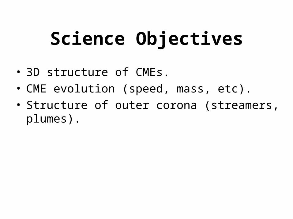
Science Objectives
• 3D structure of CMEs.• CME evolution (speed, mass, etc).• Structure of outer corona (streamers, plumes).
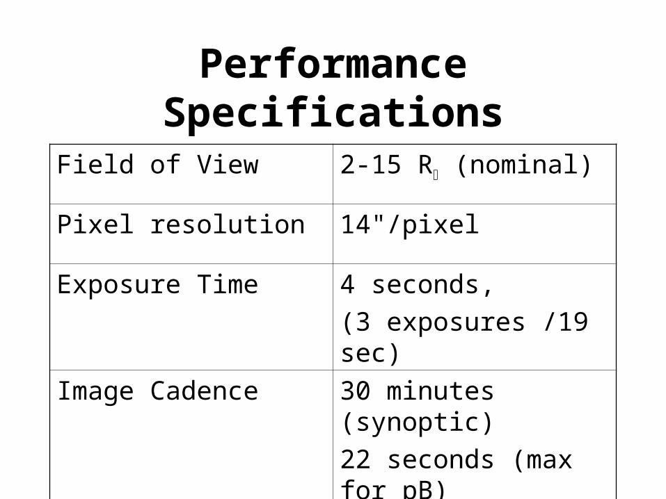
Performance Specifications
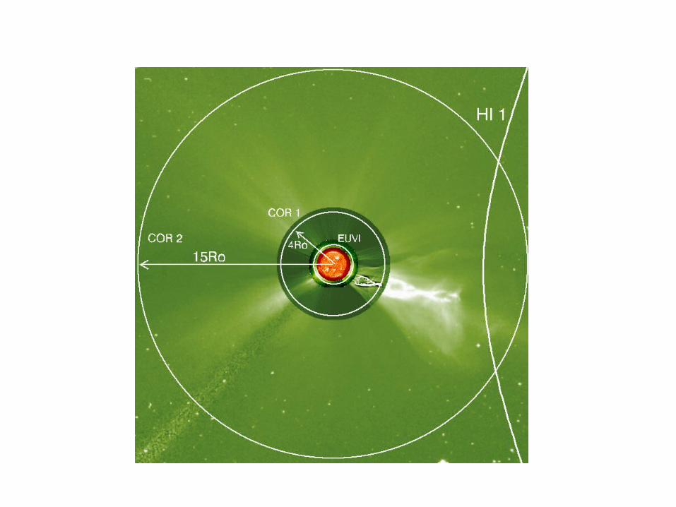
Field of View 2-15 R (nominal)
Pixel resolution 14"/pixel
Exposure Time 4 seconds,
(3 exposures /19 sec)
Image Cadence 30 minutes (synoptic)
22 seconds (max for pB)
Passband ~600-700 nm

Observing Modes
• pB sequence– Three (0, 120, 240 deg) polarizer position image set.
– Three images transmitted to the ground.
• Total B sequence– Two (0, 90 deg) polarizer position image set.
– On-board processing of images.
– Single processed image transmitted .
• ROI (Region Of Interest)– Selected sub-fields processed and transmitted.
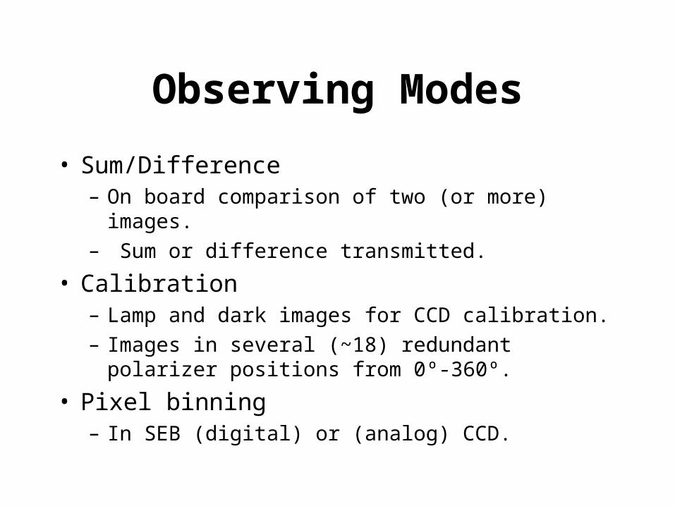
Observing Modes
• Sum/Difference– On board comparison of two (or more) images.
– Sum or difference transmitted.
• Calibration– Lamp and dark images for CCD calibration.
– Images in several (~18) redundant polarizer positions from 0º-360º.
• Pixel binning– In SEB (digital) or (analog) CCD.
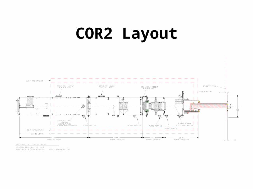
COR2 Layout
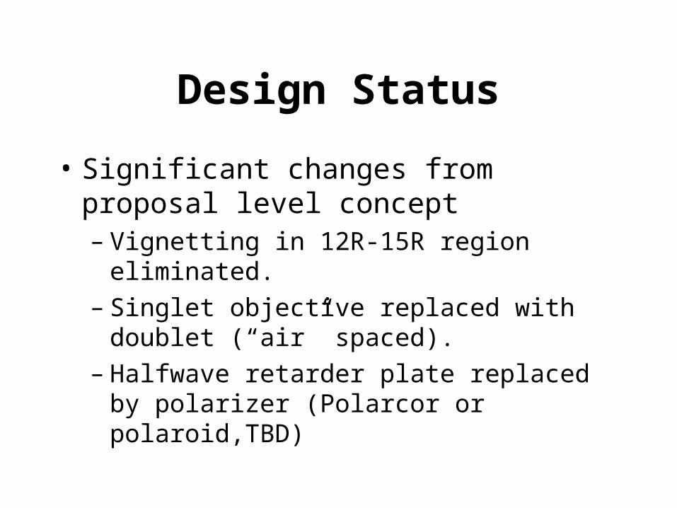
Design Status
• Significant changes from proposal level concept– Vignetting in 12R-15R region eliminated.– Singlet objective replaced with doublet (“air”
spaced).– Halfwave retarder plate replaced by polarizer
(Polarcor or polaroid,TBD)
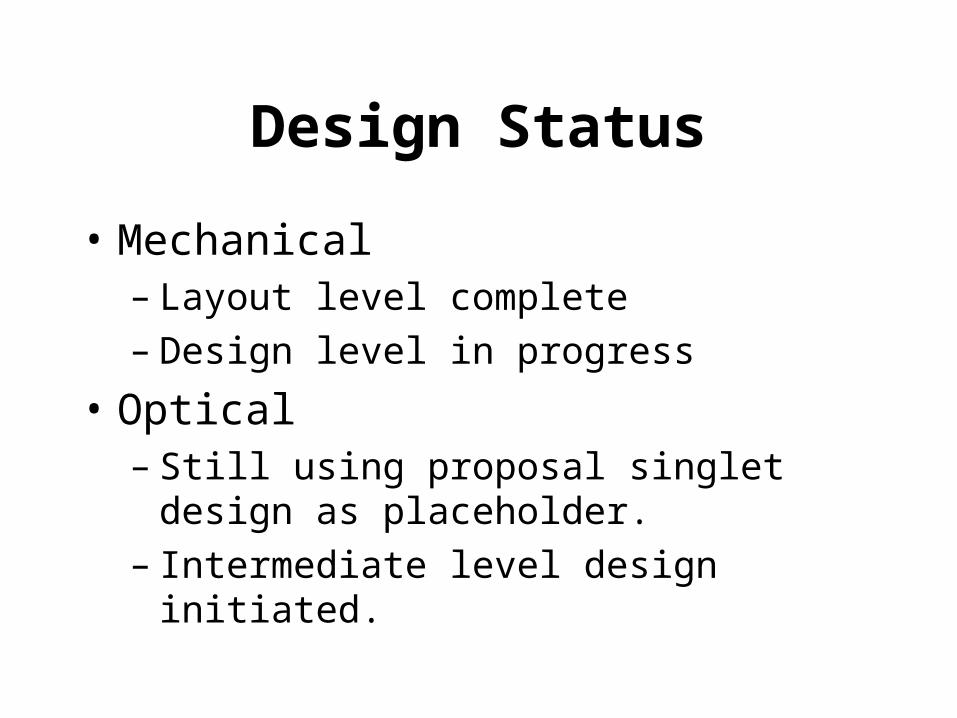
Design Status
• Mechanical– Layout level complete– Design level in progress
• Optical– Still using proposal singlet design as
placeholder.– Intermediate level design initiated.
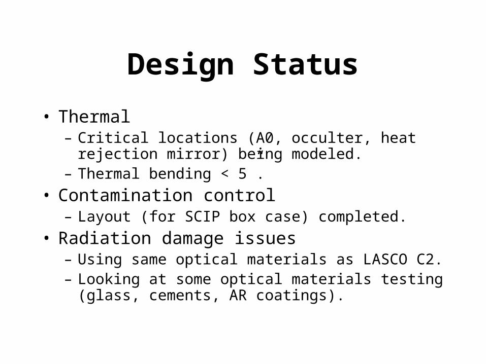
Design Status
• Thermal– Critical locations (A0, occulter, heat rejection mirror)
being modeled.– Thermal bending < 5”.
• Contamination control– Layout (for SCIP box case) completed.
• Radiation damage issues– Using same optical materials as LASCO C2.– Looking at some optical materials testing (glass,
cements, AR coatings).
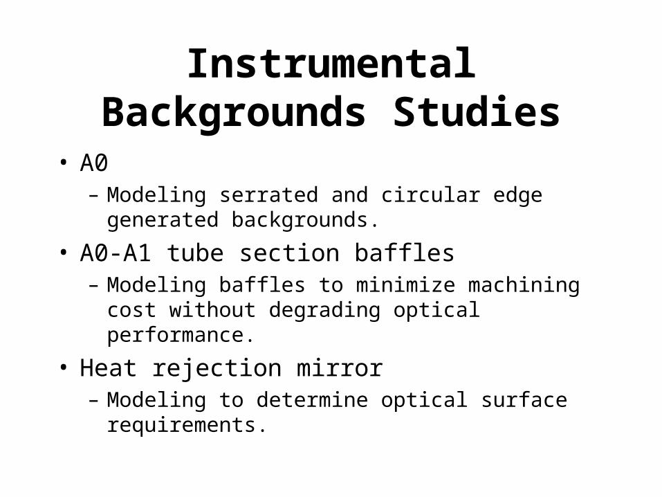
Instrumental Backgrounds Studies
• A0– Modeling serrated and circular edge generated
backgrounds.
• A0-A1 tube section baffles– Modeling baffles to minimize machining cost without
degrading optical performance.
• Heat rejection mirror– Modeling to determine optical surface requirements.
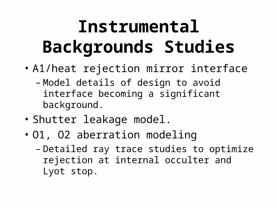
Instrumental Backgrounds Studies
• A1/heat rejection mirror interface– Model details of design to avoid interface
becoming a significant background.
• Shutter leakage model.
• O1, O2 aberration modeling– Detailed ray trace studies to optimize rejection
at internal occulter and Lyot stop.
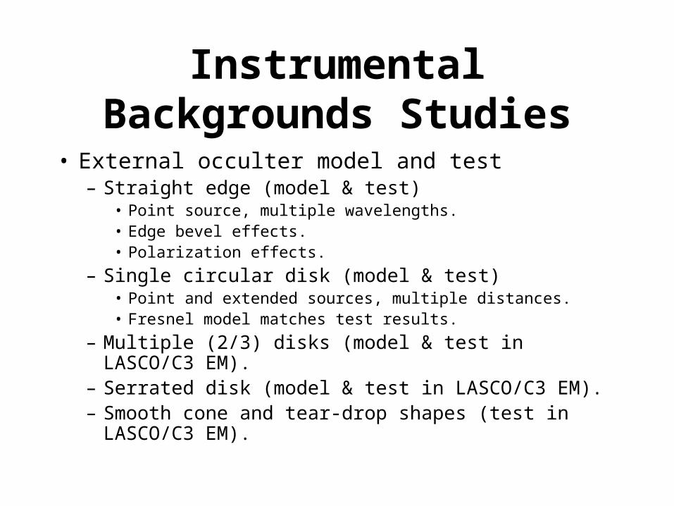
Instrumental Backgrounds Studies
• External occulter model and test– Straight edge (model & test)
• Point source, multiple wavelengths.• Edge bevel effects.• Polarization effects.
– Single circular disk (model & test)• Point and extended sources, multiple distances.• Fresnel model matches test results.
– Multiple (2/3) disks (model & test in LASCO/C3 EM).– Serrated disk (model & test in LASCO/C3 EM).– Smooth cone and tear-drop shapes (test in LASCO/C3 EM).
Instrumental Backgrounds Studies
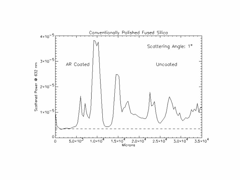
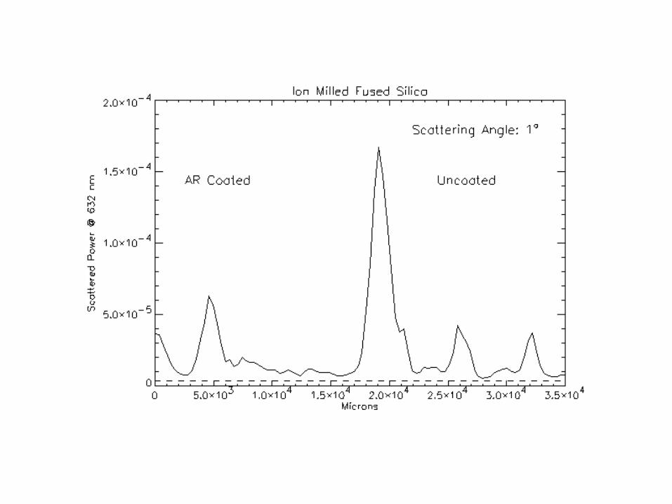
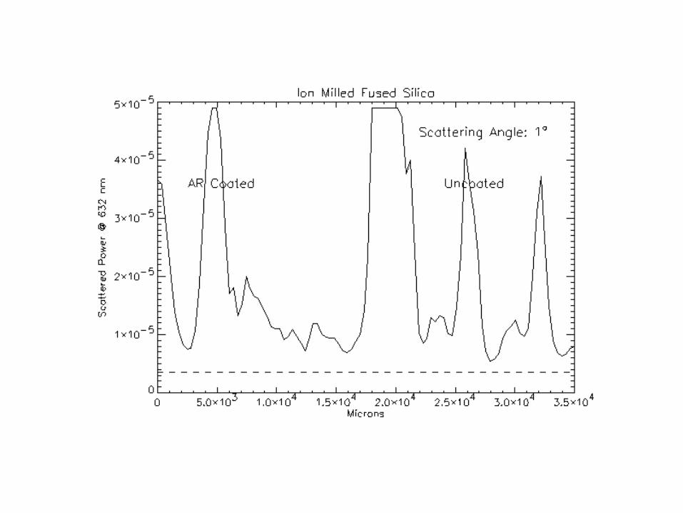
• O1 Coating and Polish Scatter Tests– Flat glass samples
• Conventionally polished (fussed silica tested, BK7 future).
• Ion milled polish (fussed silica tested, BK7 future).
• AR & non AR coated (hard coating).
– Results to date• AR coating has negligible effect on scattering.
• Scattering from samples with conventional and ion-milled surface polish is similar.
• Near-specular angles dominated by point-like defects.
Instrumental Backgrounds Studies
• Future flats tests– Flat samples of radiation resistant BK7 will be
delivered to NRL by end of July.
• Future singlet & doublet objective tests.– Aberration optimized O1 lenses will be mounted in C3
EM and stray light measured in vacuum.
Calibration
• Based on LASCO experience– LASCO in-flight calibrations verified the ground
calibrations to within <10-30% overall.
• Ground-based calibrations– Measure expected flight performance and will provide
a baseline for comparison with in-flight calibrations.
• In-flight calibrations– Measure actual performance and monitor instrument
stability.
Ground Calibrations
• Ground-based calibrations will take place at NRL Solar Instrument Test facility (Building A13).
• Calibration products include:– Radiometric calibration.
– Stray light background.
– Vignetting and distortion function.
– Filter and CCD QE and spectral response.
– Polarization calibration (polarization analyzer and instrumental polarization).
In-flight Calibrations(Door Closed)
• Diffusing window in door for photometric calibrations, measurement of instrument polarization and stability checks.
• Three LED calibration lamps at TBD locations for CCD calibrations.
• Dark images for CCD calibrations and stability checks.
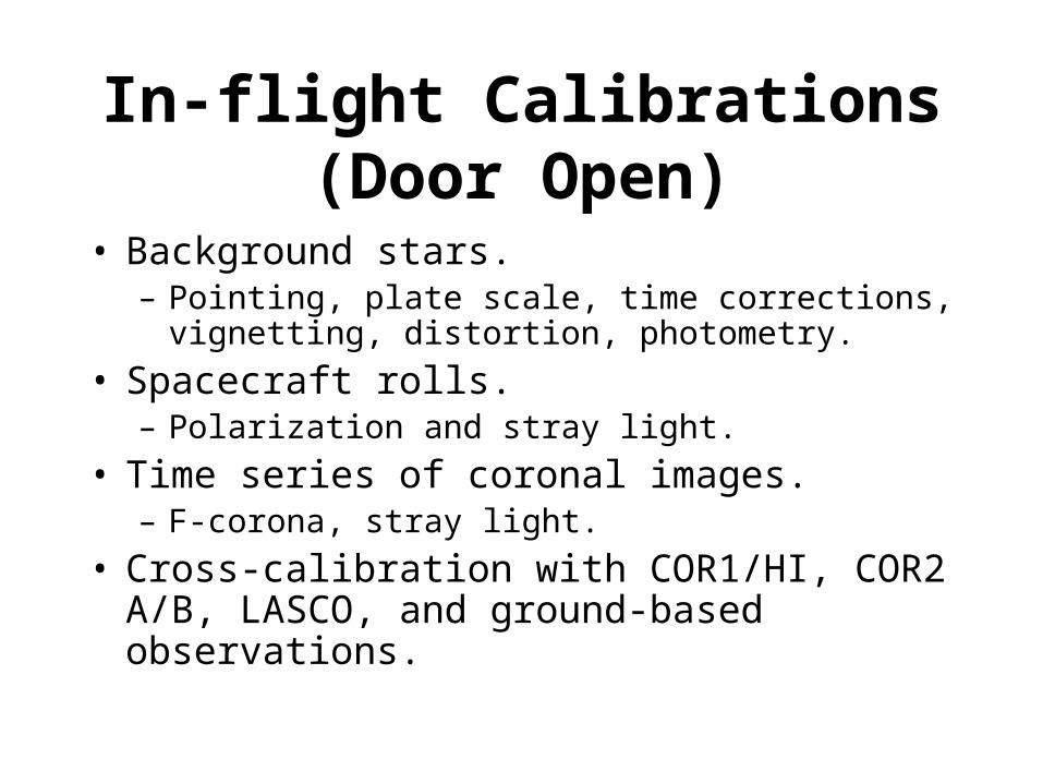
In-flight Calibrations(Door Open)
• Background stars.– Pointing, plate scale, time corrections, vignetting,
distortion, photometry.
• Spacecraft rolls.– Polarization and stray light.
• Time series of coronal images.– F-corona, stray light.
• Cross-calibration with COR1/HI, COR2 A/B, LASCO, and ground-based observations.