screening criterion for transformer thermal impact ... · project 2013 ‐03 geomagnetic ... of...
TRANSCRIPT

Screening Criterion for Transformer Thermal Impact Assessment White Paper TPL-007-2 Transmission System Planned Performance for Geomagnetic Disturbance Events
Summary Proposed TPL‐007‐2 includes requirements for entities to perform two types of geomagnetic disturbance (GMD) Vulnerability Assessments to evaluate the potential impacts of GMD events on the Bulk Electric System (BES):
The benchmark GMD Vulnerability Assessment is based on the benchmark GMD event associated with TPL‐007‐1 which standard was approved by the Federal Energy Regulatory Commission (FERC) in Order No. 830 in September 2016. The benchmark GMD event is derived from spatially‐averaged geoelectric field values to address potential wide‐area effects that could be caused by a severe 1‐in‐100 year GMD event.1
The supplemental GMD Vulnerability Assessment, based on the supplemental GMD event, is used by entities to evaluate risks that localized peaks in geomagnetic field during a severe GMD event "could potentially affect the reliable operation of the Bulk‐Power System".2 Localized enhancements of geomagnetic field can result in geoelectric field values above the spatially‐averaged benchmark in a local area.
The standard requires transformer thermal impact assessments to be performed on BES power transformers with high side, wye‐grounded windings with terminal voltage greater than 200 kV. Identified BES transformers must undergo a thermal impact assessment if the maximum effective geomagnetically‐induced current (GIC) in the transformer is equal to or greater than:
75 A per phase for the benchmark GMD event
85 A per phase for the supplemental GMD event
Based on published power transformer measurement data as described below, the respective screening criteria are conservative and, although derived from measurements in single‐phase units, are applicable to transformers with all core types (e.g., three‐limb, three‐phase).
1 See Benchmark Geomagnetic Disturbance Event Description white paper, May 12, 2016. Filed by NERC in Docket No. RM15‐11 on June 28, 2016. 2 See Order No. 830, P. 47. In Order No. 830, FERC directed NERC to develop modifications to the benchmark GMD event, included in TPL‐007‐1, such that assessments would not be based solely on spatially averaged data. The characteristics of a GMD event for this assessment are in the Supplemental GMD Event Description white paper.
Screening Criterion for Transformer Thermal Impact Assessment White Paper Project 2013‐03 Geomagnetic Disturbance Mitigation |October 2017 2
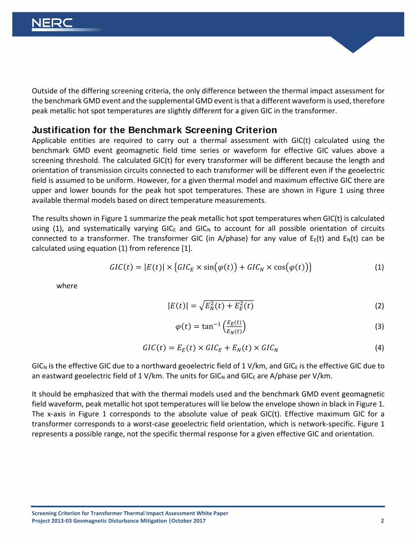
Outside of the differing screening criteria, the only difference between the thermal impact assessment for the benchmark GMD event and the supplemental GMD event is that a different waveform is used, therefore peak metallic hot spot temperatures are slightly different for a given GIC in the transformer.
Justification for the Benchmark Screening Criterion Applicable entities are required to carry out a thermal assessment with GIC(t) calculated using the benchmark GMD event geomagnetic field time series or waveform for effective GIC values above a screening threshold. The calculated GIC(t) for every transformer will be different because the length and orientation of transmission circuits connected to each transformer will be different even if the geoelectric field is assumed to be uniform. However, for a given thermal model and maximum effective GIC there are upper and lower bounds for the peak hot spot temperatures. These are shown in Figure 1 using three available thermal models based on direct temperature measurements.
The results shown in Figure 1 summarize the peak metallic hot spot temperatures when GIC(t) is calculated using (1), and systematically varying GICE and GICN to account for all possible orientation of circuits connected to a transformer. The transformer GIC (in A/phase) for any value of EE(t) and EN(t) can be calculated using equation (1) from reference [1].
| | sin cos (1)
where
| | (2)
tan (3)
(4)
GICN is the effective GIC due to a northward geoelectric field of 1 V/km, and GICE is the effective GIC due to an eastward geoelectric field of 1 V/km. The units for GICN and GICE are A/phase per V/km.
It should be emphasized that with the thermal models used and the benchmark GMD event geomagnetic field waveform, peak metallic hot spot temperatures will lie below the envelope shown in black in Figure 1. The x‐axis in Figure 1 corresponds to the absolute value of peak GIC(t). Effective maximum GIC for a transformer corresponds to a worst‐case geoelectric field orientation, which is network‐specific. Figure 1 represents a possible range, not the specific thermal response for a given effective GIC and orientation.

Screening Criterion for Transformer Thermal Impact Assessment White Paper Project 2013‐03 Geomagnetic Disturbance Mitigation |October 2017 3
Figure 1: Metallic hot spot temperatures calculated using the benchmark GMD event Red: SVC coupling transformer model [2] Blue: Fingrid model [3] Green: Autotransformer model [4]
Consequently, with the most conservative thermal models known at this point in time, the peak metallic hot spot temperature obtained with the benchmark GMD event waveform assuming an effective GIC magnitude of 75 A per phase will result in a peak temperature between 160°C and 172°C when the bulk oil temperature is 80°C (full load bulk oil temperature). The upper boundary of 172°C remains well below the metallic hot spot 200°C threshold for short‐time emergency loading suggested in IEEE Std C57.91‐2011 – Guide for Loading Mineral‐Oil‐Immersed Transformers and Step‐Voltage Regulators [5].
The selection of the 75 A per phase screening threshold is based on the following considerations:
A thermal assessment, which uses the most conservative thermal models known to date, indicates that a GIC of 75A will not result in peak metallic hot spot temperatures above 172°C. Transformer thermal assessments should not be required by Reliability Standards when results will fall well below IEEE Std C57.91‐2011 limits.

Screening Criterion for Transformer Thermal Impact Assessment White Paper Project 2013‐03 Geomagnetic Disturbance Mitigation |October 2017 4
Applicable entities may choose to carry out a thermal assessment when the effective GIC is below 75 A per phase to take into account the age or condition of specific transformers where IEEE Std C57.91‐ 2011 limits could be assumed to be lower than 200°C. Refer to IEEE Standard C57.163‐2015 Guide for Establishing Power Transformer Capability while under Geomagnetic Disturbances for additional information [6].
The models used to determine the 75 A per phase screening threshold are known to be conservative at higher values of effective GIC, especially the SVC coupling transformer model in [2].
Thermal models in peer‐reviewed technical literature, especially those calculated models without experimental validation, are less conservative than the models used to determine the screening threshold. Therefore, a technically‐justified thermal assessment for effective GIC below 75 A per phase using the benchmark GMD event geomagnetic field waveform will always result in a “pass” on the basis of the state of the knowledge at this point in time.
Based on simulations, the 75 A per phase screening threshold will result in a maximum instantaneous peak hot spot temperature of 172°C. However, IEEE Std C57.91‐2011 limits assume short term emergency operation (typically 30 minutes). As illustrated in Figure 2, simulations of the 75 A per phase screening threshold result in 30‐minute duration hot spot temperatures of about 155°C. The threshold provides an added measure of conservatism in not taking into account the duration of hot spot temperatures.
The models used in the determination of the threshold are conservative but technically justified.
Winding hot spots are not the limiting factor in terms of hot spots due to half‐cycle saturation, therefore the screening criterion is focused on metallic part hot spots only.
The 75 A per phase screening threshold was determined using single‐phase transformers, but is being applied as a screening criterion for all types of transformer construction. While it is known that some transformer types such as three‐limb, three‐phase transformers are intrinsically less susceptible to GIC, it is not known by how much, on the basis of experimentally‐supported models.

Screening Criterion for Transformer Thermal Impact Assessment White Paper Project 2013‐03 Geomagnetic Disturbance Mitigation |October 2017 5
Figure 2: Metallic hot spot temperatures calculated using the benchmark GMD eventRed: metallic hot spot temperature
Blue: GIC(t) that produces the maximum hot spot temperature with peak GIC(t) scaled to 75 A/phase
Justification for the Supplemental Screening Criterion As in the case for the benchmark GMD event discussed above, applicable entities are required to carry out thermal assessments on their BES power transformers when the effective GIC values are above a screening threshold. GIC(t) for supplemental thermal assessments is calculated using the supplemental GMD event geomagnetic field time series or waveform.
Using the supplemental GMD event waveform, a thermal analysis was completed for the two transformers that were limiting for the benchmark waveform. The results are shown in Figure 3. Peak metallic hot spot temperatures for the supplemental GMD event will lie below the envelope shown by the black line trace in Figure 3. Because the supplemental waveform has a sharper peak, the peak metallic hot spot temperatures are slightly lower than those associated with the benchmark waveform. Applying the most conservative thermal models known at this point in time, the peak metallic hot spot temperature obtained with the supplemental GMD event waveform assuming an effective GIC magnitude of 85 A per phase will result in a peak temperature of 172°C when the bulk oil temperature is 80°C (full load bulk oil temperature).3 Thus, 85 A per phase is the screening level for the supplemental waveform.
3 The temperature 172°C was selected as the screening criteria for the benchmark waveform as described in the preceding section.

Screening Criterion for Transformer Thermal Impact Assessment White Paper Project 2013‐03 Geomagnetic Disturbance Mitigation |October 2017 6
Figure 3: Metallic hot spot temperatures calculated using the supplemental GMD event Red: SVC coupling transformer model [2] Green: Autotransformer model [4]
Screening Criterion for Transformer Thermal Impact Assessment White Paper Project 2013‐03 Geomagnetic Disturbance Mitigation |October 2017 7
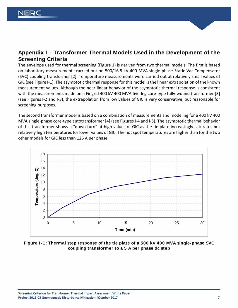
Appendix I - Transformer Thermal Models Used in the Development of the Screening Criteria The envelope used for thermal screening (Figure 1) is derived from two thermal models. The first is based on laboratory measurements carried out on 500/16.5 kV 400 MVA single‐phase Static Var Compensator (SVC) coupling transformer [2]. Temperature measurements were carried out at relatively small values of GIC (see Figure I‐1). The asymptotic thermal response for this model is the linear extrapolation of the known measurement values. Although the near‐linear behavior of the asymptotic thermal response is consistent with the measurements made on a Fingrid 400 kV 400 MVA five‐leg core‐type fully‐wound transformer [3] (see Figures I‐2 and I‐3), the extrapolation from low values of GIC is very conservative, but reasonable for screening purposes.
The second transformer model is based on a combination of measurements and modeling for a 400 kV 400 MVA single‐phase core‐type autotransformer [4] (see Figures I‐4 and I‐5). The asymptotic thermal behavior of this transformer shows a “down‐turn” at high values of GIC as the tie plate increasingly saturates but relatively high temperatures for lower values of GIC. The hot spot temperatures are higher than for the two other models for GIC less than 125 A per phase.
Figure I-1: Thermal step response of the tie plate of a 500 kV 400 MVA single-phase SVC coupling transformer to a 5 A per phase dc step
0
2
4
6
8
10
12
14
16
18
0 5 10 15 20 25 30
Time (min)
Tem
per
atu
re (
deg
. C
)

Screening Criterion for Transformer Thermal Impact Assessment White Paper Project 2013‐03 Geomagnetic Disturbance Mitigation |October 2017 8
Figure I-2: Step thermal response of the top yoke clamp of a 400 kV 400 MVA five-leg core-type fully-wound transformer to a 16.67 A per phase dc step
Figure I-3: Asymptotic thermal response of the top yoke clamp of a 400 kV 400 MVA five-leg core-type fully-wound transformer
0
5
10
15
20
25
30
35
0 5 10 15 20 25 30 35 40 45
Time (min)
Tem
per
atu
re (
deg
. C
)
0
20
40
60
80
100
120
140
160
180
200
0 10 20 30 40 50 60 70 80 90 100
GIC (A/phase)
Tem
per
atu
re (
deg
. C
)

Screening Criterion for Transformer Thermal Impact Assessment White Paper Project 2013‐03 Geomagnetic Disturbance Mitigation |October 2017 9
Figure I-4: Step thermal response of the tie plate of a 400 kV 400 MVA single-phase core-type autotransformer to a 10 A per phase dc step
Figure I-5: Asymptotic thermal response of the tie plate of a 400 kV 400 MVA single-phase core-type autotransformer
0
20
40
60
80
100
120
140
160
180
0 10 20 30 40 50 60 70 80 90 100
GIC (A/phase)
Tem
per
atu
re (
deg
. C
)

Screening Criterion for Transformer Thermal Impact Assessment White Paper Project 2013‐03 Geomagnetic Disturbance Mitigation |October 2017 10
The envelope in Figure 1 can be used as a conservative thermal assessment for effective GIC values of associated with the benchmark waveform and reference earth model (see Table 1).
Table 1: Upper Bound of Peak Metallic Hot Spot Temperatures Calculated Using the Benchmark GMD Event
Effective GIC (A/phase)
Metallic hot spot Temperature (°C)
Effective GIC (A/phase)
Metallic hot spot Temperature (°C)
0 80 100 182
10 107 110 186
20 128 120 190
30 139 130 193
40 148 140 204
50 157 150 213
60 169 160 221
70 170 170 230
75 172 180 234
80 175 190 241
90 179 200 247
For instance, if effective GIC is 130 A per phase and oil temperature is assumed to be 80°C, peak hot spot temperature is 193°C. This value is below the 200°C IEEE Std C57.91‐2011 threshold for short time emergency loading and this transformer will have passed the thermal assessment. If the full heat run oil temperature is 67°C at maximum ambient temperature, then 150 A per phase of effective GIC translates into a peak hot spot temperature of 200°C and the transformer will have passed. If the limit is lowered to 180°C to account for the condition of the transformer, then this would be an indication to “sharpen the pencil” and perform a detailed assessment. Some methods are described in Reference [1].
The temperature envelope in Figure 1 corresponds to the values of effective GIC that result in the highest temperature for the benchmark GMD event. Different values of effective GIC could result in lower temperatures using the same model. For instance, the difference in upper and lower bounds of peak temperatures for the SVC coupling transformer model for 150 A per phase is approximately 30°C. In this case, GIC(t) should be generated to calculate the peak temperatures for the actual configuration of the transformer within the system as described in Reference [1]. Alternatively, a more precise thermal assessment could be carried out with a thermal model that more closely represents the thermal behavior of the transformer under consideration.
Similar to the discussion above, the envelope in Figure 3 can be used as a conservative thermal assessment for effective GIC values of associated with the supplemental waveform (see Table 2). The supplemental waveform has a sharper peak; therefore, the peak metallic hot spot temperatures associated with the supplemental waveform for the same peak current are slightly lower than those associated with the

Screening Criterion for Transformer Thermal Impact Assessment White Paper Project 2013‐03 Geomagnetic Disturbance Mitigation |October 2017 11
benchmark waveform. In other words, for the same peak current value, the duration is relatively shorter with the supplemental waveform, and shorter duration means lower temperature. However, higher peak currents will occur with the supplemental benchmark, therefore, higher peak hot spot temperatures will occur. Comparing Tables 1 and 2 shows the magnitude of this difference.
Table 2: Upper Bound of Peak Metallic Hot Spot Temperatures Calculated Using the Supplemental GMD Event
Effective GIC (A/phase)
Metallic hot spot Temperature (°C )
Effective GIC(A/phase)
Metallic hot spot Temperature (°C )
0 80 120 188
10 107 130 191
20 124 140 194
30 137 150 198
40 147 160 203
50 156 170 209
60 161 180 214
70 162 190 229
75 165 200 237
80 169 220 248
85 172 230 253
90 177 250 276
100 181 275 298
110 185 300 316

Screening Criterion for Transformer Thermal Impact Assessment White Paper Project 2013‐03 Geomagnetic Disturbance Mitigation |October 2017 12
References [1] Transformer Thermal Impact Assessment white paper. Developed by the Project 2013‐03 (Geomagnetic
Disturbance) standard drafting team. October 2017. Available at: http://www.nerc.com/pa/stand/Pages/TPL0071RI.aspx
[2] Marti, L; Rezaei‐Zare, A.; and Narang, A. "Simulation of Transformer Hotspot Heating due to Geomagnetically Induced Currents." IEEE Transactions on Power Delivery, vol.28, no.1, pp.320‐327, Jan. 2013.
[3] Lahtinen, M. and Elovaara, J. “GIC occurrences and GIC test for 400 kV system transformer”. IEEE Transactions on Power Delivery, Vol. 17, No. 2. April 2002.
[4] Raith, J. and Ausserhofer, S. “GIC Strength verification of Power Transformers in a High Voltage Laboratory”, GIC Workshop, Cape Town, April 2014
[5] "IEEE Guide for Loading Mineral‐Oil‐Immersed Transformers and Step‐Voltage Regulators." IEEE Std C57.91‐2011 (Revision of IEEE Std C57.91‐1995).
[6] “IEEE Guide for Establishing Power Transformer Capability while under Geomagnetic Disturbances.” IEEE Std C57.163‐2015.