safety manual sil relay module -...
TRANSCRIPT
ISO9001
3
RELAY MODULEKFD0-RSH-1.4S.PS2
PROCESS AUTOMATION
SAFETY MANUAL SIL

With regard to the supply of products, the current issue of the following document is applicable: The General Terms of Delivery for Products and Services of the Electrical Industry, published by the
Central Association of the Electrical Industry (Zentralverband Elektrotechnik und Elektroindustrie (ZVEI) e.V.) in its most recent version as well as the supplementary clause: "Expanded reservation
of proprietorship"
SAFETY MANUAL SIL KFD0-RSH-1.4S.PS2

SAFETY MANUAL SIL KFD0-RSH-1.4S.PS2Contents
2255
38 20
11-0
4
3
1 Introduction......................................................................... 41.1 General Information.......................................................................................41.2 Intended Use ................................................................................................41.3 Manufacturer Information ..............................................................................51.4 Relevant Standards and Directives ...............................................................5
2 Planning .............................................................................. 62.1 System Structure...........................................................................................6
2.1.1 Low Demand Mode .................................................................................62.1.2 High Demand Mode .................................................................................6
2.2 Assumptions ................................................................................................72.3 Safety Function and Safe State .....................................................................82.4 Characteristic Safety Values .........................................................................9
3 Safety Recommendation.................................................. 103.1 Interfaces ....................................................................................................103.2 Configuration ..............................................................................................103.3 Useful Life Time ..........................................................................................103.4 Installation and Commissioning ..................................................................11
4 Proof Test .......................................................................... 124.1 Proof Test Procedure ..................................................................................12
5 Abbreviations.................................................................... 16

2255
38 20
11-0
4
4
SAFETY MANUAL SIL KFD0-RSH-1.4S.PS2Introduction
1 Introduction1.1 General Information
This manual contains information for application of the device in functional safety related loops.The corresponding data sheets, the operating instructions, the system description, the Declaration of Conformity, the EC-Type-Examination Certificate, the Functional Safety Assessment and applicable Certificates (see data sheet) are integral parts of this document.The documents mentioned are available from www.pepperl-fuchs.com or by contacting your local Pepperl+Fuchs representative.Mounting, commissioning, operation, maintenance and dismounting of any devices may only be carried out by trained, qualified personnel. The instruction manual must be read and understood.When it is not possible to correct faults, the devices must be taken out of service and action taken to protect against accidental use. Devices should only be repaired directly by the manufacturer. De-activating or bypassing safety functions or failure to follow the advice given in this manual (causing disturbances or impairment of safety functions) may cause damage to property, environment or persons for which Pepperl+Fuchs GmbH will not be liable. The devices are developed, manufactured and tested according to the relevant safety standards. They must only be used for the applications described in the instructions and with specified environmental conditions, and only in connection with approved external devices.
1.2 Intended UseThis signal conditioner is a loop powered safety relay module with a logic input and two different relay outputs:It can be used as an interface in output loops for fire and gas systems classified as SIL3. The safe state in this application is energized to safe (ETS). Output I with two relays in parallel must be used, no fuse available.It can also be used as an interface in output loops for ESD (Emergency Shut Down) systems classified as SIL3. The safe state in this application is de-energized to safe (DTS). Output II with two relays in series must be used. An additional fuse in series to the relay contacts is available (see chapter 3).With both outputs in combination a non safety application for dual pole switching (DPS) is possible.Additionally a test input for proof tests is available. The proof test checks if each single relay is working correctly.The device is usually mounted on a DIN rail in cabinets with access for qualified personnel only.

SAFETY MANUAL SIL KFD0-RSH-1.4S.PS2Introduction
2255
38 20
11-0
4
5
1.3 Manufacturer InformationPepperl+Fuchs GmbHLilienthalstrasse 20068307 Mannheim/GermanyKFD0-RSH-1.4S.PS2Up to SIL3 (for DTS), up to SIL3 (for ETS)
1.4 Relevant Standards and DirectivesDevice specific standards and directives
■ Functional safety IEC 61508 part 1 – 7, edition 2000:Standard of functional safety of electrical/electronic/programmable electronic safety-related systems (product manufacturer)
■ Electromagnetic compatibility:- EN 61326-1:2006- NE 21:2006
System specific standards and directives■ Functional safety IEC 61511 part 1 – 3, edition 2003:
Standard of functional safety: safety instrumented systems for the process industry sector (user)
2255
38 20
11-0
4
6
SAFETY MANUAL SIL KFD0-RSH-1.4S.PS2Planning
2 Planning2.1 System Structure2.1.1 Low Demand Mode
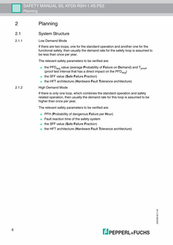
If there are two loops, one for the standard operation and another one for the functional safety, then usually the demand rate for the safety loop is assumed to be less than once per year.The relevant safety parameters to be verified are:
■ the PFDavg value (average Probability of Failure on Demand) and Tproof (proof test interval that has a direct impact on the PFDavg)
■ the SFF value (Safe Failure Fraction)■ the HFT architecture (Hardware Fault Tolerance architecture)
2.1.2 High Demand ModeIf there is only one loop, which combines the standard operation and safety related operation, then usually the demand rate for this loop is assumed to be higher than once per year.The relevant safety parameters to be verified are:
■ PFH (Probability of dangerous Failure per Hour)■ Fault reaction time of the safety system ■ the SFF value (Safe Failure Fraction)■ the HFT architecture (Hardware Fault Tolerance architecture)

SAFETY MANUAL SIL KFD0-RSH-1.4S.PS2Planning
2255
38 20
11-0
4
7
2.2 AssumptionsThe following assumptions have been made during the FMEDA analysis:
■ Failure rates are constant, wear out mechanisms are not included.■ The stress levels are average for an industrial environment and can be
compared to the Ground Fixed Classification of MIL-HNBK-217F. Alternatively, the assumed environment is similar to:
• IEC 60654-1 Class C (sheltered location) with temperature limits within the manufacturer's rating and an average temperature over a long period of time of 40 ºC. Humidity levels are assumed within manufacturer's rating. For a higher average temperature of 60 ºC, the failure rates should be multiplied with an experience based factor of 2.5. A similar multiplier should be used if frequent temperature fluctuation must be assumed.
■ Failure rate based on the Siemens SN29500 data base.■ It was assumed that the appearance of a safe error (e. g. output in safe state)
would be repaired within 8 hours.■ During the absence of the device for repairing, measures have to be taken to
ensure the safety function (for example: substitution by an equivalent device).■ For high currents and high ambient temperature the de-rating given in the data
sheet needs to be considered.■ The input of the device must be connected to a safety PLC which has
minimum the SIL needed in the loop.■ The device shall claim less than 10 % of the total failure budget for a
SIL3 safety loop.■ For a SIL3 application operating in Low Demand Mode the total PFDavg value
of the SIF (Safety Instrumented Function) should be smaller than 10-3, hence the maximum allowable PFDavg value would then be 10-4.
■ For a SIL3 application operating in High Demand Mode of operation the total PFH value of the SIF should be smaller than 10-7 per hour, hence the maximum allowable PFH value would then be 10-8 per hour.
■ Since the circuit has a Hardware Fault Tolerance of 0 and it is a type A component, the SFF must be > 90 % according to table 2 of IEC 61508-2 for SIL3 (sub)system.

2255
38 20
11-0
4
8
SAFETY MANUAL SIL KFD0-RSH-1.4S.PS2Planning
2.3 Safety Function and Safe StateDTSSafety FunctionThe safety function of the device is defined: Whenever the input of the device is de-energized, the DTS output is not conducting.Safe StateFor the DTS safety function the safe state is defined as the DTS output being open (not conducting).Reaction TimeThe reaction time is < 20 ms.ETSSafety FunctionThe safety function of the device is defined: Whenever the input of the device is energized, the ETS output is conducting.Safe StateFor the ETS safety function the safe state is defined as the ETS output being closed (conducting).Reaction TimeThe reaction time is < 20 ms.DPSThe dual pole switching application is no safety application.GeneralFor all applications the maximum switching frequency is limited to 10 Hz.

SAFETY MANUAL SIL KFD0-RSH-1.4S.PS2Planning
2255
38 20
11-0
4
9
2.4 Characteristic Safety Values
The characteristic safety values like PFD/PFH, SFF, HFT and Tproof are taken from the SIL report/FMEDA report. Please note, PFD and Tproof are related to each other.The function of the devices has to be checked within the proof test interval (Tproof).
Parameters acc. to IEC 61508 VariablesAssessment type and documentation
Full assessment
Pepperl+Fuchs FMEDA report 1 FS-0042EA-20ADevice type ADemand mode Low Demand Mode or High Demand ModeSafety function 2 ETS 4 DTSHFT 0 0SIL 3 3λsd + λsu 139.7 FIT 144.77 FITλdd 0 FIT 0 FITλdu 7.1 FIT 1.83 FITλtotal (safety function) 146.6 FIT 146.6 FITSFF 95.2 % 98.7 %MTBF 3 639 years 560 yearsPFH 7.1 x 10⁻⁹ 1/h 1.83 x 10⁻⁹ 1/hPFDavg for T1 = 1 year 3.1 x 10⁻⁵ 8.01 x 10⁻⁶
Tproof max. 3 years 12 yearsReaction time < 20 ms1 Pepperl+Fuchs documentation number2 The device can be used in two safety functions, ETS (energized to safe) and DTS (de-energized to safe).3 acc. to SN29500. This value includes failures which are not part of the safety function/MTTR = 8 h.4 For ETS in SIL2 applications no proof test has to be carried out, the calculated proof time is higher than the useful time (Tproof max. for ETS SIL2 is 32 years).

2255
38 20
11-0
4
10
SAFETY MANUAL SIL KFD0-RSH-1.4S.PS2Safety Recommendation
3 Safety Recommendation3.1 Interfaces
The device has the following interfaces. For corresponding terminals see data sheet.
■ Safety relevant interfaces: input, output I (ETS), output II (DTS)■ To avoid contact welding in DTS application we recommend to use a serial
fuse in the load circuit. This can be the internal fuse F1 or any external fuse of max. 5 A nominal value.
■ Test input interface may not be used during normal operation (only for proof test)
3.2 ConfigurationA configuration of the device is not necessary and not possible.ETS, DTS and DPS can be selected by using the referring terminals. See data sheet. The fuse in delivery status (2.5 A) can be changed to max 5 A. Please note the temperature derating according to the data sheet.
3.3 Useful Life TimeAlthough a constant failure rate is assumed by the probabilistic estimation this only applies provided that the useful life time of components is not exceeded. Beyond this useful life time, the result of the probabilistic calculation is meaningless as the probability of failure significantly increases with time. The useful life time is highly dependent on the component itself and its operating conditions – temperature in particular (for example, the electrolytic capacitors can be very sensitive to the working temperature).This assumption of a constant failure rate is based on the bathtub curve, which shows the typical behavior for electronic components.Therefore it is obvious that failure calculation is only valid for components that have this constant domain and that the validity of the calculation is limited to the useful life time of each component.It is assumed that early failures are detected to a huge percentage during the installation period and therefore the assumption of a constant failure rate during the useful life time is valid.However, according to IEC 61508-2, a useful life time, based on experience, should be assumed. Experience has shown that the useful life time often lies within a range period of about 8 ... 12 years.

SAFETY MANUAL SIL KFD0-RSH-1.4S.PS2Safety Recommendation
2255
38 20
11-0
4
11
Our experience has shown that the useful life time of a Pepperl+Fuchs product can be higher
■ if there are no components with reduced life time in the safety path (like electrolytic capacitors, relays, flash memory, opto coupler) which can produce dangerous undetected failures and
■ if the ambient temperature is significantly below 60 °C.Please note that the useful life time refers to the (constant) failure rate of the device. The effective life time can be higher.Maximum Switching Power of Output ContactsThe useful life time is limited by the maximum switching cycles under load conditions. You can see the relationship between the maximum switching power and the load conditions in the diagram below.
Figure 3.1
3.4 Installation and CommissioningInstallation has to consider all aspects regarding the SIL level of the loop. During installation or replacement of the device the loop has to shut down. Devices have to be replaced by the same type of devices.
1
0
I (A)
2
5
30100502010 200
115253
220U (V)
Resistive loadAC
Resistive loadDC
0.5
0.20.1
0.3
0.6
max. 105switching cycles
max. 3 x 10⁴switching cycles
2255
38 20
11-0
4
12
SAFETY MANUAL SIL KFD0-RSH-1.4S.PS2Proof Test
4 Proof Test4.1 Proof Test Procedure
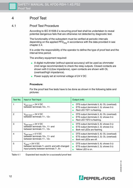
According to IEC 61508-2 a recurring proof test shall be undertaken to reveal potential dangerous fails that are otherwise not detected by diagnostic test.The functionality of the subsystem must be verified at periodic intervals depending on the applied PFDavg in accordance with the data provided in see chapter 2.4.It is under the responsibility of the operator to define the type of proof test and the interval time period.The ancillary equipment required:
■ A digital multimeter (without special accuracy) will be used as ohmmeter (mid range recommended) to check the relay outputs. Closed contacts are shown with 0 Ω (low impedance), open contacts are shown with OL (overload/high impedance).
■ Power supply set at nominal voltage of 24 V DC
Procedure:For the proof test five tests have to be done as shown in the following table and pictures:
Test No. Input or Test Input Output (mA)1 Vtest input = 24 V DC
between terminals 10+, 11-■ DTS output (terminals 5, 6): OL (overload)■ ETS output (terminals 2, 3): shows 0 Ω■ Red LED TST1 is flashing.
2 Vtest input = 24 V DCbetween terminals 11-, 12+
■ DTS output (terminals 5, 6): OL (overload)■ ETS output (terminals 2, 3): shows 0 Ω■ Red LED TST2 is flashing.
3 Vtest input = 24 V DCbetween terminals 10+, 11- andbetween terminals 11-, 12+
■ DTS output (terminals 5, 6): shows 0 Ω■ ETS output (terminals 2, 3): shows 0 Ω■ Both red LEDs are flashing.
4 Vtest input = 0 V DCbetween terminals 10+, 11- andbetween terminals 11-, 12+
■ DTS output (terminals 5, 6): OL (overload)■ ETS output (terminals 2, 3): OL (overload)■ Both red LEDs are off.
5 Vinput = 24 V DCbetween terminals 7+ and 8- and with changed input polarity between terminals 7-, 8+
■ DTS output (terminals 5, 6): shows 0 Ω■ ETS output (terminals 2, 3): shows 0 Ω■ Yellow LED is on.
Table 4.1 Expected test results for a successful proof test

SAFETY MANUAL SIL KFD0-RSH-1.4S.PS2Proof Test
2255
38 20
11-0
4
13
Figure 4.1 Proof test set-up for KFD0-RSH-1.4S.PS2, test 1
Figure 4.2 Proof test set-up for KFD0-RSH-1.4S.PS2, test 2
4
5
6
2
3
10+
12
11-
24 V
Multimeter(Ω )
Multimeter(Ω )
10
12+
11-24 V
4
5
6
2
3
Multimeter(Ω )
Multimeter(Ω )

2255
38 20
11-0
4
14
SAFETY MANUAL SIL KFD0-RSH-1.4S.PS2Proof Test
Figure 4.3 Proof test set-up for KFD0-RSH-1.4S.PS2, test 3
Figure 4.4 Proof test set-up for KFD0-RSH-1.4S.PS2, test 4
4
5
6
2
3
24 V
24 V
Multimeter(Ω )
Multimeter(Ω )
10+
12+
11-
4
5
6
2
3
0 V
0 V
Multimeter(Ω )
Multimeter(Ω )
10+
12+
11-

SAFETY MANUAL SIL KFD0-RSH-1.4S.PS2Proof Test
2255
38 20
11-0
4
15
Figure 4.5 Proof test set-up for KFD0-RSH-1.4S.PS2, test 5Only if all tests are successfully done, the proof test is successfull.
7
4
5
6
2
3 8(+/-)24 V
Multimeter(Ω )
Multimeter(Ω )
2255
38 20
11-0
4
16
SAFETY MANUAL SIL KFD0-RSH-1.4S.PS2Abbreviations
5 AbbreviationsFMEDA Failure Mode, Effects and Diagnostics AnalysisHFT Hardware Fault TolerancePFDavg Average Probability of Failure on DemandPFH Probability of dangerous Failure per HourPTC Proof Test CoverageSFF Safe Failure FractionSIF Safety Instrumented FunctionSIL Safety Integrity LevelSIS Safety Instrumented SystemTproof Proof Test Interval
DPS Dual Pole SwitchingDTS De-energized To Safe StateESD Emergency Shut DownETS Energized To Safe State
SAFETY MANUAL SIL KFD0-RSH-1.4S.PS2Notes
2255
38 20
11-0
4
17

Subject to modificationsCopyright PEPPERL+FUCHS • Printed in Germany
www.pepperl-fuchs.com
Worldwide HeadquartersPepperl+Fuchs GmbH68307 Mannheim · GermanyTel. +49 621 776-0E-mail: [email protected]
For the Pepperl+Fuchs representative closest to you check www.pepperl-fuchs.com/pfcontact
PROCESS AUTOMATION – PROTECTING YOUR PROCESS
225538 TDOCT-2052CENG04/2011