manual - pepperl+fuchsfiles.pepperl-fuchs.com/selector_files/navi/productinfo/doct/tdoct... ·...
TRANSCRIPT

PROCESS AUTOMATION
MANUAL
TIMER RELAYKF**-DU-EX1.D
ISO9001

With regard to the supply of products, the current issue of the following document is applicable:The general terms of delivery for products and services of the electrical industry, as published
by the central association of the "Elektrotechnik und Elektroindustrie (ZVEI) e.V.",including the supplementary clause "Extended reservation of title".

Edi
tion
03/2
009
1124
05
1
Timer Relay KF**-DU-Ex1.DTable of Contents
1 Symbols Used . . . . . . . . . . . . . . . . . . . . . . . . . . . . . . . . . . . . . . . . . . . . . . 3
2 Overview . . . . . . . . . . . . . . . . . . . . . . . . . . . . . . . . . . . . . . . . . . . . . . . . . . 32.1 Range of application . . . . . . . . . . . . . . . . . . . . . . . . . . . . . . . . . . . . . . . . . . . . . . . . . . 3
2.2 Model variants. . . . . . . . . . . . . . . . . . . . . . . . . . . . . . . . . . . . . . . . . . . . . . . . . . . . . . . . 4
2.3 Inputs and outputs . . . . . . . . . . . . . . . . . . . . . . . . . . . . . . . . . . . . . . . . . . . . . . . . . . . . 5
3 Safety Notes. . . . . . . . . . . . . . . . . . . . . . . . . . . . . . . . . . . . . . . . . . . . . . . . 6
4 Explosion Protection . . . . . . . . . . . . . . . . . . . . . . . . . . . . . . . . . . . . . . . . 7
5 Installation and Connection . . . . . . . . . . . . . . . . . . . . . . . . . . . . . . . . . . 75.1 Installation. . . . . . . . . . . . . . . . . . . . . . . . . . . . . . . . . . . . . . . . . . . . . . . . . . . . . . . . . . . 7
5.2 Connection . . . . . . . . . . . . . . . . . . . . . . . . . . . . . . . . . . . . . . . . . . . . . . . . . . . . . . . . . . 8
5.2.1 Connection input (field circuit) . . . . . . . . . . . . . . . . . . . . . . . . . . . . . . . . . . . . . . . . . . . . 95.2.2 Connection output. . . . . . . . . . . . . . . . . . . . . . . . . . . . . . . . . . . . . . . . . . . . . . . . . . . . . 10
5.3 Indicating and operating elements . . . . . . . . . . . . . . . . . . . . . . . . . . . . . . . . . . . . . . 11
6 Parameterization menu overview . . . . . . . . . . . . . . . . . . . . . . . . . . . . . 12
7 Editing device data . . . . . . . . . . . . . . . . . . . . . . . . . . . . . . . . . . . . . . . . . 147.1 Display mode . . . . . . . . . . . . . . . . . . . . . . . . . . . . . . . . . . . . . . . . . . . . . . . . . . . . . . . 14
7.2 Main menu. . . . . . . . . . . . . . . . . . . . . . . . . . . . . . . . . . . . . . . . . . . . . . . . . . . . . . . . . . 15
7.3 Input . . . . . . . . . . . . . . . . . . . . . . . . . . . . . . . . . . . . . . . . . . . . . . . . . . . . . . . . . . . . . . . 16
7.3.1 Input: Line Monitoring . . . . . . . . . . . . . . . . . . . . . . . . . . . . . . . . . . . . . . . . . . . . . . . . . . 177.3.2 Input: Edge . . . . . . . . . . . . . . . . . . . . . . . . . . . . . . . . . . . . . . . . . . . . . . . . . . . . . . . . . . 18

Edi
tion
03/2
009
1124
05
Timer Relay KF**-DU-Ex1.DTable of Contents
2
7.4 Output . . . . . . . . . . . . . . . . . . . . . . . . . . . . . . . . . . . . . . . . . . . . . . . . . . . . . . . . . . . . . 19
7.4.1 Output: Function . . . . . . . . . . . . . . . . . . . . . . . . . . . . . . . . . . . . . . . . . . . . . . . . . . . . . . 207.4.2 Output: Mode (mode of operation) . . . . . . . . . . . . . . . . . . . . . . . . . . . . . . . . . . . . . . . . 217.4.3 Output: Time . . . . . . . . . . . . . . . . . . . . . . . . . . . . . . . . . . . . . . . . . . . . . . . . . . . . . . . . . 217.4.4 Output: Divider . . . . . . . . . . . . . . . . . . . . . . . . . . . . . . . . . . . . . . . . . . . . . . . . . . . . . . . 227.4.5 Output: Pulse Time . . . . . . . . . . . . . . . . . . . . . . . . . . . . . . . . . . . . . . . . . . . . . . . . . . . . 237.4.6 Output: Rel (Relay) . . . . . . . . . . . . . . . . . . . . . . . . . . . . . . . . . . . . . . . . . . . . . . . . . . . . 247.4.7 Output: Alarm Freeze . . . . . . . . . . . . . . . . . . . . . . . . . . . . . . . . . . . . . . . . . . . . . . . . . . 247.4.8 Switching behavior of the outputs . . . . . . . . . . . . . . . . . . . . . . . . . . . . . . . . . . . . . . . . . 257.4.9 Behavior of the time relay with input pulses < 1 ms . . . . . . . . . . . . . . . . . . . . . . . . . . . 30
7.5 Service . . . . . . . . . . . . . . . . . . . . . . . . . . . . . . . . . . . . . . . . . . . . . . . . . . . . . . . . . . . . . 31
7.5.1 Service: Password . . . . . . . . . . . . . . . . . . . . . . . . . . . . . . . . . . . . . . . . . . . . . . . . . . . . 317.5.2 Service: Language . . . . . . . . . . . . . . . . . . . . . . . . . . . . . . . . . . . . . . . . . . . . . . . . . . . . 33

Edi
tion
03/2
009
1124
05
3
Timer Relay KF**-DU-Ex1.DSymbols Used
1 Symbols Used
2 Overview
2.1 Range of application
The K-System devices from Pepperl+Fuchs are used for transmitting signals between field devices and a process control system/control system.
The devices marked with "Ex" in the type designation are suitable for the connection of field devices used in potentially explosive atmospheres. Safe field circuits for these devices are intrinsically safe and are galvanically isolated from non-intrinsically safe circuits. The devices thus establish an electromagnetic separation between the potentially explosive atmospheres and the safe areas in a system.
This symbol warns of possible danger. Failure to heed this warning may result in personal injury or death, or property damage, including destruction.
This symbol warns the user of a possible fault.Failure to heed this warning can lead to total failure of the device and any other connected equipment.
This symbol draws attention to important information.
Warning
Attention
Note

Edi
tion
03/2
009
1124
05
Timer Relay KF**-DU-Ex1.DOverview
4
The KF**-DU-Ex1.D timer relays of the K-System (DU for short) can be used to transform input pulses in various ways, thus processing them for the evaluation.
You can use a timer relay to record rapid counter pulses, for example, or to extend very short pulses, thus to process signals from pipe inspection devices with a slow PLC.
Parameters are set for the DU with an integrated control panel.
More information (for example, certificates and data sheets for the DU devices and the operating manual for the K-System) can be found on our webpage www.pepperl-fuchs.com (enter *DU* in the product search).
2.2 Model variants
The timer relay is available in three versions:
• KFD2-DU-Ex1.D with a power supply of 24 V DC
• KFA5-DU-Ex1.D with a power supply of 115 V AC
• KFA6-DU-Ex1.D with a power supply of 230 V AC
The device must not be used without additional overvoltage protection in distributed DC networks.
Note

Edi
tion
03/2
009
1124
05
5
Timer Relay KF**-DU-Ex1.DOverview
2.3 Inputs and outputs
A K-System DU from Pepperl+Fuchs has
• an intrinsically safe input (blue terminal block) to which a NAMUR sensor or a mechanical contact can be connected and
• two outputs, specifically − one relay output and− one potential free transistor output, as well as
• a non-intrinsically safe input for prematurely ending a time function once it has been started (reset of outputs), please see also section 5.2.2.
Field device input
Outputs, Reset input, power supply

Edi
tion
03/2
009
1124
05
Timer Relay KF**-DU-Ex1.DSafety Notes
6
3 Safety Notes
The Timer Relay KF**-DU-Ex1.D must only be operated by trained personnel in accordance with this handbook.
The protection of operating personnel and of the system is only ensured if the devices are used in accordance with their intended purpose. Any other type of operation than that described in this manual places the safety and functionality of the devices and systems connected to them in question.
The devices may only be installed, connected, and adjusted by electrical professionals outside the hazardous area.
If faults cannot be eliminated, the devices must be taken out of operation and protected from being placed in service again inadvertently. Devices must only be repaired directly by the manufacturer Pepperl+Fuchs. Tampering with or making changes to the devices is dangerous and therefore not permitted. They render the warranty void.
The responsibility for the adherence to local safety standards lies with the operator.
Warning
Warning
Warning
Warning
Note

Edi
tion
03/2
009
1124
05
7
Timer Relay KF**-DU-Ex1.DExplosion Protection
4 Explosion Protection
atmosphere, please observe the guideline 1999/92/EC (ATEX 137) or the corresponding national guidelines.
For secondary explosion protection, that is, for measures to hinder the ignition of a surrounding explosive atmosphere by electrical devices, Pepperl+Fuchs will gladly make the "Explosion Protection Manual" available to you for a nominal free.
Note in particular DIN EN 60079-10, DIN EN 60079-14, DIN EN 50014 and DIN EN 50020, or the corresponding national guidelines.
Pepperl+Fuchs also offers a seminar on the topic of explosion protection.
5 Installation and Connection
5.1 Installation
The devices of the K-system from Pepperl+Fuchs and thus also the Timer Relay KF**-DU-Ex1.D can be mounted on a 35 mm standard rail corresponding to DIN EN 60175. The devices must be snapped onto the rail vertically, and never slanted or tipped to the side.
Additional possibilities for mounting, e. g. using the Power Rail, can be found in the data sheets and in the K-System operating manual on our webpage www.pepperl-fuchs.com (enter *DU* in the product search).
The Timer Relay KF**-DU-Ex1.D is constructed in protection degree IP20 and must therefore be protected from undesirable ambient conditions (water, small foreign objects).
PROCESS AUTOMATION
MANUAL
EXPLOSION PROTECTION
Intrinsic SafetyExplosion Protection
Attention

Edi
tion
03/2
009
1124
05
Timer Relay KF**-DU-Ex1.DInstallation and Connection
8
Dimensions ofKF**-DU-Ex1.D in mm (")
5.2 Connection
The removable terminals of the KF-series considerably simplify the connection and the switch cabinet assembly. They make it possible to replace devices quickly and without error if a customer service becomes necessary.
Terminals are equipped with screws, are self-opening, have a large connection area for a wire cross-section up to 2.5 mm² and coded plugs, making it impossible to mix them up.
40 mm (1.6") 115 mm (4.5'')
10
5 m
m (
4.1
'')
11
9 m
m (
4.7
'')
7 m
m
(0.2
8'')

Edi
tion
03/2
009
1124
05
9
Timer Relay KF**-DU-Ex1.DInstallation and Connection
5.2.1 Connection input (field circuit)
The intrinsically safe field circuit is connected at the blue terminals 1 ... 3 of the KF**-DU-Ex1.D. These may be guided into the potentially explosive areas with connector cables in accordance with DIN EN 60079-14. Terminal 2 always remains free.
You may connect:
• a sensor in accordance with DIN EN 60947-5-6 (NAMUR)
• a mechanical contact
If there is a mechanical contact you can add the following externally (as close as possible to the contact):
• A parallel resistor for lead break monitoring
• A series resistor for short circuit monitoring
In reference to these monitoring options, please see also section 7.3.1.
Terminals 4 ... 6, 7 ... 9 and 16 ... 18 do not exist on the DU.
Zone 0, 1, 2Div. 1, 2
KFD2-DU-Ex1.D
3-
1+
Power Rail
24 V DCERR
10 kΩ10 kΩ
400 Ω ≤ R ≤ 2 kΩ

Edi
tion
03/2
009
1124
05
Timer Relay KF**-DU-Ex1.DInstallation and Connection
10
5.2.2 Connection output
The green terminals serve the following functions:
• Terminals 10 ... 12: relay output
• Terminals 13 and 14: Reset input (15 free)
• Terminals 16 ... 18: transistor output
• Terminals 23 and 24: power supply (22 free)
More information on connecting the DU (e. g. using the Power Rail) can be found in the data sheets and the K-System operating manual on our webpage www.pepperl-fuchs.com (enter *DU* in the product search).
If the KF**-DU-Ex1.D is operated with mechanical contacts, debounced contacts must be used.
Note
Zone 2Div. 2
KFD2-DU-Ex1.D
101112
I
13+14-
24 V DC23+24-
Power Rail
24 V DCERR
II19+
20-
Edi
tion
03/2
009
1124
05
11
Timer Relay KF**-DU-Ex1.DInstallation and Connection
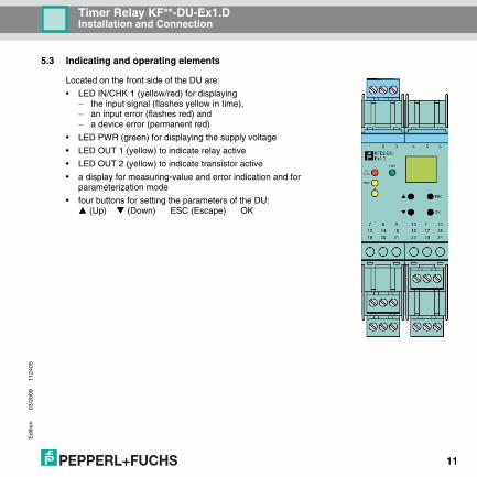
5.3 Indicating and operating elements
Located on the front side of the DU are:
• LED IN/CHK 1 (yellow/red) for displaying− the input signal (flashes yellow in time),− an input error (flashes red) and− a device error (permanent red)
• LED PWR (green) for displaying the supply voltage
• LED OUT 1 (yellow) to indicate relay active
• LED OUT 2 (yellow) to indicate transistor active
• a display for measuring-value and error indication and for parameterization mode
• four buttons for setting the parameters of the DU: (Up) (Down) ESC (Escape) OK

Edi
tion
03/2
009
1124
05
Timer Relais KF**-DU-Ex1.DParameterization menu overview
12
6 Parameterization menu overview
The following figure should serve as a reference for quick orientation, particularly when you are already familiar with how to parameterize the DU. A detailed description of the operating steps can be found in section 7. Menu items that appear in grey are only visible for certain output functions.
Display mode Input Line Monitoring LB
Edge SC
Output Function Single Pulse
Mode Retrigg. Single Pulse
Time Pulse Stretching
Divider Limit. Pulse
Pulse Time Switch On Delay
Continued on next page.

Edi
tion
03/2
009
1124
05
13
Timer Relais KF**-DU-Ex1.DParameterization menu overview
Rel (Relay) Switch Off Delay
Alarm freeze Repeater
Pulse Divider
Service Password
Language

Edi
tion
03/2
009
1124
05
Timer Relay KF**-DU-Ex1.DEditing device data: Display mode
14
7 Editing device data
7.1 Display mode
In normal mode the following is displayed:
• If one of the time functions Single Pulse, Retrigg. Single Pulse, Pulse Stretching, Limit. Pulse, Switch On Delay or Switch Off Delay is started (see section 7.4.8), the elapsed time is shown in the first line of the display in seconds. The second line of the display shows the ratio of the elapsed time to the overall time of the time function with a bar diagram. When the time has elapsed, 0 is displayed.
• There is no display for the Repeater function (see section 7.4.1). The display shows 0.
• For the Pulse Divider function (see section 7.4.1), the number of input pulses since the last output pulse is shown in the first line of the display. The second line of the display shows by means of a bar diagram the increase in the number of input pulses until the next output pulse.
In the event of an error, an error message is displayed (if appropriately parameterized) until corrected:
• Err device for a device error
• Err SC for a short circuit in the sensor line
• Err LB for an interruption in the sensor line
To select the error messages see section 7.3. The outputs always revert to a no-current state when there is a malfunction.
If alarm freeze (see section 7.4.7) has been triggered, a message to that effect will be displayed in the second line of the display.
You can prematurely end a time function that has been started with a signal of at least 100 ms on the Reset input (terminals 13/14). The outputs are reset: If you have selected mode of operation passive (see section 7.4.2), they are energized; otherwise the are de-energized.

Edi
tion
03/2
009
1124
05
15
Timer Relay KF**-DU-Ex1.DEditing device data: Main menu
7.2 Main menu
To change to the Main menu of the parameterization mode from the display mode, simultaneously press the ESC and OK buttons for approx. 1 second.
The Main menu consists of 3 menu items (Input, Output, Service). You can switch between them using the ▲ and ▼ buttons. With the ESC button, you can return at any time from the Main menu to the display mode.
You can prevent unauthorized persons from making changes in the parameterization mode by means of a password (see section 7.5.1). While it is possible in this case to view the various settings in the parameterization mode before entering a password, no changes can be made. The first time an attempt is made to change a setting, the device automatically prompts the user for a password. The password must be entered once each time you change from display mode to parameterization mode. The entry is described in section 7.5.1.
If no button is pressed for 10 minutes while in the parameterization mode, the device automatically returns to the display mode.
OK
ESC
ESC
2 0 . 0 1
Err LB
+
Main menu
Display modee.g.:
Input
Output
Service

Edi
tion
03/2
009
1124
05
Timer Relay KF**-DU-Ex1.DEditing device data: Input
16
7.3 Input
From the menu option Input of the Main menu, you can use the OK button to switch to the Input menu.
This consists of 1 or 2 menu options (Line Monitoring and Edge). You can switch between these options with the ▲ and ▼ buttons.
The Edge menu item does not appear unless you have selected Repeater or Pulse Divider as a time function (see section 7.4.1).
With the ESC button, you can return at any time from the Input menu to the Main menu.
OK
ESCInput
Edge
Input menu
LineMonitoring

Edi
tion
03/2
009
1124
05
17
Timer Relay KF**-DU-Ex1.DEditing device data: Input
7.3.1 Input: Line Monitoring
From the Line Monitoring menu option in the Input menu, you can use the OK button to switch to the Line Monitoring menu.
This menu consists of two 2 menu options (LB for lead break and SC for short circuit). You can switch between these options with the ▲ and ▼ buttons.
With the ESC button, you can return at any time from the Input menu to the Line Monitoring menu.
From the LB menu option in the Line Monitoring menu, you can use the OK button to select lead breakage monitoring for the sensor input (ON or OFF).
Correspondingly, from the SC menu option in the Line Monitoring menu, you can use the OK button to select short-circuit monitoring for the sensor input (ON or OFF).
OK
ESC
LineMonitoring
SC
Line Monitoring menu
LB
OK
ESC
ESC
OFF
ON
OK = save
LB/SC
LB/SC
LB/SC

Edi
tion
03/2
009
1124
05
Timer Relay KF**-DU-Ex1.DEditing device data: Input
18
The setting is modified as follows:
• The current selection is shown with a flashing display. You can use the ▲ and ▼ buttons to switch back and forth among the various possibilities. When you stop pressing the ▲ or ▼ buttons, the value that has just been selected is displayed.
• If you press the ESC button, the old value will be appear again in the flashing display.
• If you press the ESC button a second time, you will go back to the higher-level menu without any changes being made.
• If you press the OK button while a value is flashing, the value will be saved, and will then be displayed without flashing.
• After that you can return to the higher-level menu with the ESC button.
When lead fault monitoring is active, the system tests for terminal 3 whether no current is flowing (LB) or whether the input current is too high (SC).
For lead break monitoring, an appropriate parallel resistor must be present in the sensor or externally. For short-circuit monitoring, an appropriate series resistor must be present in the sensor or externally (see section 5.2.1).
7.3.2 Input: Edge
The Edge menu item of the Input menu does not appear unless you have selected Repeater or Pulse Divider as a time function (see section 7.4.1).
From the Edge menu item, you can use the OK button to select the mode of operation for the (rise or fall).
The method for changing the setting is described in section 7.3.
On the effect of the Edge on switching behavior and the transistor see section 7.4.8.
OK
ESC
ESC OK = save
Edge
rise
fall

Edi
tion
03/2
009
1124
05
19
Timer Relay KF**-DU-Ex1.DEditing device data: Output
7.4 Output
From the menu option Output of the Main menu, you can use the OK button to switch to the Output menu.
This consists at least of the menu items Function, Rel (Relay) and Alarm Freeze. Depending on the time function selected (see section 7.4.1) the following menu items may appear in addition: Mode, Time, Divider, and Pulse Time. You can switch back and forth between the menu items with the ▲ and ▼ buttons.
The Mode menu item does not appear unless you have selected Single Pulse, Retrigg. Single Pulse, Pulse Stretching or Limit. Pulse a time function (see section 7.4.1).
The Time menu item does not appear unless you have selected Repeater or Pulse Divider as a time function (see section 7.4.1).
The Divider and Pulse Time menu items do not appear unless you have selected Pulse Divider as a time function (see section 7.4.1).
With the ESC button, you can return at any time from the Trip value menu to the Output menu.
OK
ESCOutput
Time
Mode
Output menu
Function
AlarmFreeze
Rel (Relay)
Divider
Pulse Time
Edi
tion
03/2
009
1124
05
Timer Relay KF**-DU-Ex1.DEditing device data: Output
20
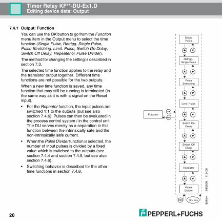
7.4.1 Output: Function
You can use the OK button to go from the Function menu item in the Output menu to select the time function (Single Pulse, Retrigg. Single Pulse, Pulse Stretching, Limit. Pulse, Switch On Delay, Switch Off Delay, Repeater or Pulse Divider).
The method for changing the setting is described in section 7.3.
The selected time function applies to the relay and the transistor output together. Different time functions are not possible for the two outputs.
When a new time function is saved, any time function that may still be running is terminated (in the same way as it is with a signal on the Reset input).
• For the Repeater function, the input pulses are switched 1:1 to the outputs (but see also section 7.4.6). Pulses can then be evaluated in the process control system / in the control unit. The DU serves merely as a separation in this function between the intrinsically safe and the non-intrinsically safe current.
• When the Pulse Divider function is selected, the number of input pulses is divided by a fixed value which is switched to the outputs (see section 7.4.4 and section 7.4.5, but see also section 7.4.6).
• Switching behavior is described for the other time functions in section 7.4.8.
OK
ESC
ESC OK = save
Function
Limit. Pulse
PulseStretching
SinglePulse
Retrigg. Single Pulse
PulseDivider
Repeater
Switch OnDelay
Switch OffDelay

Edi
tion
03/2
009
1124
05
21
Timer Relay KF**-DU-Ex1.DEditing device data: Output
7.4.2 Output: Mode (mode of operation)
The Mode menu item of the output menu does not appear unless you have selected Single Pulse, Retrigg. Single Pulse, Pulse Stretching or Limit. Pulse as a time function (see section 7.4.1).
From the Mode menu option you can use the OK button to select the mode of operation for the two outputs (active or passive).
The two outputs always have the same mode of operation.
On the effect of the mode of operation on switching behavior and the transistor see section 7.4.8.
The method for changing the setting is described in section 7.3.
7.4.3 Output: Time
The Time menu item of the Output menu does not appear unless you have selected Repeater or Pulse Divider as a time function (see section 7.4.1).
From the Time menu item, you can use the OK button to make adjustments to the time value.
You can set values to between 0.010 sec and 60 min.
OK
ESC
ESC OK = save
Mode
passive
active
ESC
OK
ESC OK = save
Time2 0 . 0 1
sec

Edi
tion
03/2
009
1124
05
Timer Relay KF**-DU-Ex1.DEditing device data: Output
22
To change the setting, proceed as follows (the decimal point is moved automatically):
• The current value is displayed flashing. You can change this value with the ▲ and ▼ buttons. If you press the ▲ or ▼ button, the value will change incrementally. If you hold down the ▲ or ▼ button somewhat longer, the setting will "roll" to higher or lower values. If you stop pressing the ▲ or ▼ button, the value that was just set will flash.
• If you press the ESC button, the old value will be appear again in the flashing display.
• If you press the ESC button a second time, you will go back to the higher-level menu without any changes being made.
• If you press the OK button while a value is flashing, the value will be saved, and will then be displayed without flashing.
• After that you can return to the higher-level menu with the ESC button.
When a new time value is saved, any time function that may still be running is terminated (the same way it is with a signal on the Reset input).
On the effect of time t on switching behavior and the transistor see section 7.4.8.
7.4.4 Output: Divider
The Divider menu item of the Output menu does not appear unless you have selected Pulse Divider as a time function (see section 7.4.1).
From the Divider menu item you can use the OK button to adjust the separator value.
The value may be between 1,000 and 9999. The number of input pulses is divided by this value and switched to the outputs (but see also section 7.4.6).
The method for changing the setting is described in section 7.4.3. The decimal point is moved automatically.
2 0 0 0ESC
OK
ESC OK = save
Divider

Edi
tion
03/2
009
1124
05
23
Timer Relay KF**-DU-Ex1.DEditing device data: Output
7.4.5 Output: Pulse Time
The Pulse Time menu item of the Output menu does not appear unless you have selected Pulse Divider as a time function (see section 7.4.1).
From the Pulse Time menu item you can use the OK button to select a pulse time of (1 ms, 50 ms, 500 ms or 1000 ms).
The method for changing the setting is described in section 7.3.
The frequency that is generated on the outputs is not constant, but rather a number of pulses per unit of time that may vary irregularly with a maximum of 10 pulses per second (but see also section 7.4.6).
Where the following must hold:
Example:
Maximum input frequency 4 kHz, pulse divider 2000
The following must be true:Pulse Time < 0.25 x 0.5 s = 0.125 s
The pulse time should therefore be selected at 50 ms.
OK
ESC
ESC
1ms
50ms
OK = save
1000ms
500ms
Pulse Time
Pulse Time < ¼ x Pulse Divider
Max. input frequency

Edi
tion
03/2
009
1124
05
Timer Relay KF**-DU-Ex1.DEditing device data: Output
24
7.4.6 Output: Rel (Relay)
From the Rel (Relay) menu item of the Output menu, you can use the OK button to select activation for the relay (ON or OFF).
The method for changing the setting is described in section 7.3.
Normally the relay and the transistor output switch simultaneously: Note however:
On the other side, the transistor output is only designed for connection values 40 V DC/50 mA (see data sheet).
7.4.7 Output: Alarm Freeze
You can use the OK button to select Alarm Freeze (ON or OFF) from the Alarm Freeze menu item in the Output menu.
The method for changing the setting is described in section 7.3.
Alarm Freeze can be used to prevent very brief periods when line faults were present (Err LB, Err SC; section 7.3) from going unnoticed by the operating personnel.
The maximum switching frequency of the relay is < 2 Hz. The relay must therefore be de-activated for short switching times (OFF) to prevent it from being destroyed.
OK
ESC
ESC
OFF
ON
OK = save
Rel (Relay)
Attention
OK
ESC
ESC
OFF
ON
OK = save
AlarmFreeze

Edi
tion
03/2
009
1124
05
25
Timer Relay KF**-DU-Ex1.DEditing device data: Output
If you have selected Alarm Freeze On, an error message remains in the display after a fault and no current is supplied to the outputs. This continues until one of the following actions is performed:
• Restarting the device
• Press the ESC button
Each of these actions causes the error message and alarm freeze to be deleted and the outputs to be reset unless there is still a lead fault.
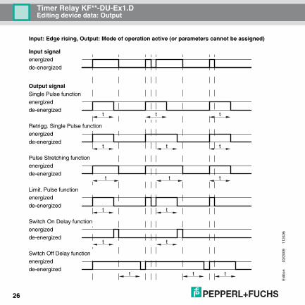
7.4.8 Switching behavior of the outputs
Normally the relay and the transistor output switch simultaneously: You should nevertheless note section 7.4.6.
For the operating behavior for the various time functions, please refer to the following illustrations. On the functions Repeater and Pulse Divider, please refer to section 7.4.1.
Edi
tion
03/2
009
1124
05
Timer Relay KF**-DU-Ex1.DEditing device data: Output
26
Input: Edge rising, Output: Mode of operation active (or parameters cannot be assigned)
t
t t
t
t t
t t
t
t
t t t
t tt
energized
de-energized
energized
de-energized
energized
de-energized
energized
de-energized
energized
de-energized
Input signal
energized
de-energized
Single Pulse function
energized
Output signal
Switch Off Delay function
Switch On Delay function
Limit. Pulse function
Pulse Stretching function
Retrigg. Single Pulse function
de-energized

Edi
tion
03/2
009
1124
05
27
Timer Relay KF**-DU-Ex1.DEditing device data: Output
Input: Edge falling, Output: Mode of operation active (or parameters cannot be assigned)
t
t t
t
t t
t t
t
t
t t t
t tt
energized
de-energized
energized
de-energized
energized
de-energized
energized
de-energized
energized
de-energized
Input signal
energized
de-energized
energized
Output signal
de-energized
Single Pulse function
Switch Off Delay function
Switch On Delay function
Limit. Pulse function
Pulse Stretching function
Retrigg. Single Pulse function

Edi
tion
03/2
009
1124
05
Timer Relay KF**-DU-Ex1.DEditing device data: Output
28
Input: Edge rising, Output: Mode of operation passive
t t
t t
t t
t
t
t t t
energized
de-energized
energized
de-energized
energized
de-energized
Input signal
energized
de-energized
energized
Output signal
de-energized
Single Pulse function
Limit. Pulse function
Pulse Stretching function
Retrigg. Single Pulse function

Edi
tion
03/2
009
1124
05
29
Timer Relay KF**-DU-Ex1.DEditing device data: Output
Input: Edge falling, Output: Mode of operation passive
t t
t t
t t
t
t
t t t
energized
de-energized
energized
de-energized
energized
de-energized
Input signal
energized
de-energized
energized
Output signal
de-energized
Single Pulse function
Limit. Pulse function
Pulse Stretching function
Retrigg. Single Pulse function
Edi
tion
03/2
009
1124
05
Timer Relay KF**-DU-Ex1.DEditing device data: Output
30
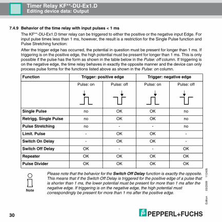
7.4.9 Behavior of the time relay with input pulses < 1 ms
The KF**-DU-Ex1.D timer relay can be triggered to either the positive or the negative input Edge. For input pulse times less than 1 ms, however, the result is a restriction for the Single Pulse function and Pulse Stretching function:
After the trigger edge has occurred, the potential in question must be present for longer than 1 ms. If triggering is on the positive edge, the high potential must be present for longer than 1 ms. This is only possible if the pulse has the form as shown in the table below in the Pulse: off column. If triggering is on the negative edge, the time relay behaves in exactly the opposite manner and the device can only process pulse forms for the functions listed above as shown in the Pulse: on column.
Function Trigger: positive edge Trigger: negative edge
Pulse: on Pulse: off Pulse: on Pulse: off
Single Pulse no OK OK no
Retrigg. Single Pulse no OK OK no
Pulse Stretching no - - no
Limit. Pulse - OK OK -
Switch On Delay - OK OK -
Switch Off Delay OK - - OK
Repeater OK OK OK OK
Pulse Divider OK OK OK OK
Please note that the behavior for the Switch Off Delay function is exactly the opposite. This means that if the Switch Off Delay is triggered for the positive edge of a pulse that is shorter than 1 ms, the lower potential must be present for more than 1 ms after the negative edge. If triggering is on the negative edge, the high potential must correspondingly be present for more than 1 ms after the positive edge.
Note

Edi
tion
03/2
009
1124
05
31
Timer Relay KF**-DU-Ex1.DEditing device data: Service
7.5 Service
You can enter the Service menu by pressing OK on the Service menu item in the main menu.
This menu consists of 2 menu items (Password and Language). You can switch back and forth between them with the ▲ and ▼ buttons.
With the ESC button, you can return at any time from the Service menu to the main menu.
7.5.1 Service: Password
Activating password protection
From the menu option Password of the Service menu, you can use the OK button to access the selection of password protection (ON or OFF).
The method for changing the setting is described in section 7.3.
When the DU is delivered from the factory, password protection is inactive. The password cannot be changed and is 1234.
OK
ESC
Service menu
Service
Language
Password
OK
ESC
ESC
OFFPass
ONPass
OK = save
Password
Edi
tion
03/2
009
1124
05
Timer Relay KF**-DU-Ex1.DEditing device data: Service
32
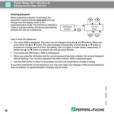
Entering password
When password protection is activated, the password must be entered once each time you change from the display mode to the parameterization mode. The first time an attempt is made to change a setting, the device automatically prompts the user for a password.
How to enter the password:
• The value 0000 is displayed. The value can be changed using the ▲ and ▼ buttons. When you press either the ▲ or ▼ button, the value changes incrementally. If either the ▲ or ▼ button is pressed for a longer period of time, the setting "rolls" to higher or lower values, respectively. If neither the ▲ nor ▼ button is pressed, the new set value flashes.
• If you press the ESC button, 0000 is redisplayed.
• When you press the OK button and the correct password has been entered, the value is displayed without flashing. If an incorrect password has been entered, 0000 is displayed again.
• Use the ESC button to return to the position at which you would like to change a setting.
If you have entered the correct password, you may now make your changes. If the correct password was not entered, no parameterization changes may be made.
0 0 0 0Pass
OK
ESC
ESC
Attemptedchange
Edi
tion
03/2
009
1124
05
33
Timer Relay KF**-DU-Ex1.DEditing device data: Service
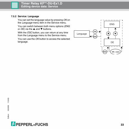
7.5.2 Service: Language
You can set the language value by pressing OK on the Language menu item in the Service menu.
You can switch between both menu options (ENG or DE) via the ▲ and ▼ buttons.
With the ESC button, you can return at any time from the Language menu to the Service menu.
You can use the OK button to access the selected language. DE
ENG
OK
ESC
ESC OK = save
Language

Edi
tion
03/2
009
1124
05
Timer Relay KF**-DU-Ex1.DNotes
34

With regard to the supply of products, the current issue of the following document is applicable: The general terms of delivery for products and services of the electrical industry, as published
by the Central Association of the "Elektrotechnik und Elektroindustrie (ZVEI) e.V.", including the supplementary clause "Extended ownership rights".

Subject to modifications
Copyright PEPPERL+FUCHS • Printed in Germany
www.pepperl-fuchs.com
Worldwide HeadquartersPepperl+Fuchs GmbH
68307 Mannheim · Germany
Tel. +49 621 776-0
E-mail: [email protected]
USA HeadquartersPepperl+Fuchs Inc.
Twinsburg, Ohio 44087 · USA
Tel. +1 330 4253555
E-mail: [email protected]
Asia Pacific HeadquartersPepperl+Fuchs Pte Ltd.
Company Registration No. 199003130E
Singapore 139942
Tel. +65 67799091
E-mail: [email protected]
PROCESS AUTOMATION – PROTECTING YOUR PROCESS
DOCT-0498A 112405
03/2009