quick start guide vbp-hh1-v3.0-v1 -...
TRANSCRIPT

VBP-HH1-V3.0-V1AS-Interface Handheld
FACTORY AUTOMATION
QUICK START GUIDE

With regard to the supply of products, the current issue of the following document is ap-plicable: The General Terms of Delivery for Products and Services of the Electrical Indus-
try, published by the Central Association of the Electrical Industry (Zentralverband Elektrotechnik und Elektroindustrie (ZVEI) e.V.) in its most recent version as well as the
supplementary clause: "Expanded reservation of proprietorship"
VBP-HH1-V3.0-V1
VBP-HH1-V3.0-V1
3
1 Introduction................................................................................. 4
1.1 Purpose of this quick start guide ....................................................... 4
1.2 Product documentation on the internet............................................. 4
2 Product Description ................................................................... 5
2.1 Use and application of the handheld ................................................. 5
2.2 Delivery package.................................................................................. 5
2.3 Displays and controls.......................................................................... 6
2.3.1 AS-Interface connection adapter ....................................................... 7
2.3.2 LC display.......................................................................................... 7
2.3.3 Button assignment............................................................................. 8
2.3.4 Button combinations .......................................................................... 8
2.3.5 Connections....................................................................................... 9
2.3.6 Application example (VBP-HH1-V3.0-V1 only)................................. 10
3 Commissioning......................................................................... 11
3.1 Preparation ......................................................................................... 11
4 Operation................................................................................... 13
4.1 Addressing operating mode ............................................................. 13
4.2 Further operating modes .................................................................. 14

22
13
36
20
14
-12
4
VBP-HH1-V3.0-V1Introduction
1 Introduction
1.1 Purpose of this quick start guide
This quick start guide contains basic instructions for operating the device. However, the manual takes priority over the quick start guide.
1.2 Product documentation on the internet
You can view all the relevant documentation and additional information on your product at http://www.pepperl-fuchs.com. Simply enter the product name or model number in the Product/Key word search box and click Search.
Select your product from the list of search results. Click on the information you require in the product information list, e.g., Technical documents.
A list of all available documents is displayed.

VBP-HH1-V3.0-V1Product Description
22
13
36
20
14
-12
5
2 Product Description
2.1 Use and application of the handheld
AS-Interface slaves are usually addressed with a handheld. As a rule, a number of steps are necessary to address the slaves and in the future you will be able to execute this procedure faster using the handheld:
■ Unique addressing of the AS-Interface slaves
■ Power supply to the AS-Interface slaves via the handheld
■ Function checks – even without programmable logic controller (PLC)
2.2 Delivery package
The delivery package contains:
VBP-HH1-V3.0
VBP-HH1-V3.0-110V VBP-HH1-V3.0-V1
VBP-HH1-V3.0-KIT
VBP-HH1-V3.0-KIT-110V
■ Addressing device
■ Charger
■ Quick start guide
■ Addressing device
■ Charger
■ Quick start guide
■ Two programming cable:
VAZ-PK-1.5M-V1-G and
V1-G-0.3M-PVC-V1-G
■ Addressing device
■ Charger
■ Quick start guide
■ Case
■ Four programming cable:
VAZ-PK-1.5M-V1-G, V1S-
G-1M-PUR1, V1-G-0.3M-
PUR-V1-G2 and VAZ-PK-
FK-0.2M-V1-W3
1.VBP-HH1-V3.0-KIT-110V only
2.VBP-HH1-V3.0-KIT-110V only
3.VBP-HH1-V3.0-KIT-110V only
22
13
36
20
14
-12
6
VBP-HH1-V3.0-V1Product Description
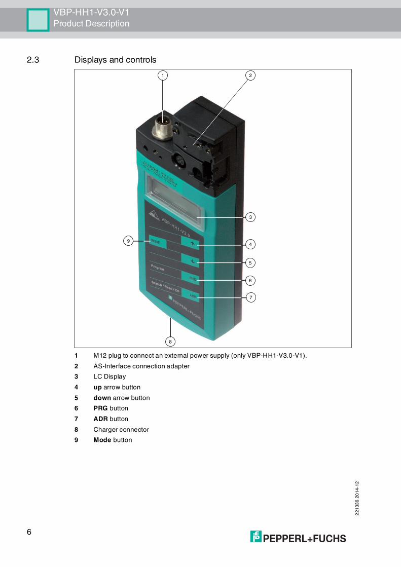
2.3 Displays and controls
1 M12 plug to connect an external power supply (only VBP-HH1-V3.0-V1).
2 AS-Interface connection adapter
3 LC Display
4 up arrow button
5 down arrow button
6 PRG button
7 ADR button
8 Charger connector
9 Mode button
8
3
7
6
5
49
1 2

VBP-HH1-V3.0-V1Product Description
22
13
36
20
14
-12
7
2.3.1 AS-Interface connection adapter
The AS-Interface connection adapter on the top of the addressing device is used to connect AS-Interface nodes (sensors, actuators, and interface modules) to the addressing device. The following devices and models can be connected directly to the addressing device by plugging into the AS-Interface connecting adapter:
■ Devices with M12 plug
■ VariKont M-System
■ VariKont-System
■ FP models
■ AS-Interface modules (*-G1, *-G4, *-G16)
For models with an integrated addressing jack, please use the VAZ-PK-1.5M-V1-G adapter cable.
only VBP-HH1-V3.0-V1:
An additional M12 plug is provided on the front of the housing. It provides a connection option for an external bulk power, AUX, for nodes. Due to the integrated decoupling coils, you can connect a DC or AS-i voltage to supply the slaves and save battery charge. A extension cable is provided with the delivery package in case an extension is required.
2.3.2 LC display
Address and data display
Depending on the operating mode, two digits and the letters A and B are used to display various information in this area of the display.
■ The address of the currently selected AS-Interface node differs according to the AS-Interface specification supported and the address areas Standard (shown without letters), A and B.
■ Target address which is to be communicated to the currently selected AS-Interface node
■ Display of read data
1 Address and data display
2 Address field
3 Operating mode display
ADDR
ID12
IO
DATA
PARA
PERI
RD
WR AB
1 2 3 4 5 6 7 8 9 10 11 12 13 14 16 16 17
18 19 20 21 22 23 24 25 26 27 28 29 30 31
A
B
3
1
2

22
13
36
20
14
-12
8
VBP-HH1-V3.0-V1Product Description
■ Display of data to be written
Address field
All the AS-Interface nodes of the AS-Interface network are shown in this area of the display:
■ If the addressing device detects AS-Interface nodes from various address areas, the various address areas are identified in the right-hand section of the address field, as follows:
• Without letters: For AS-Interface nodes that do not support the AS-Interface specification 2.1.
• A: For AS-Interface nodes belonging to address area A.
• B: For AS-Interface nodes belonging to address area B.
The display of the detected addresses in the respective address area changes every 2 seconds.
■ The addresses of all AS-Interface nodes currently connected to the addressing device are shown in the Addressing operating mode by flashing digits. In all other operating modes, the addresses of the AS-Interface nodes shown flashing are those being actively accessed.
■ During Addressing, the non-flashing digits represent addresses of AS-Interface nodes that have been assigned addresses by the addressing device.
Operating mode display
The current operating mode is shown in this area of the display.
2.3.3 Button assignment
2.3.4 Button combinations
Button Description
Set values (e.g.slave address, ID1 data, slave parameters, slave data), change of operating mode
Set values (e.g. slave address, ID1 data, slave parameters, slave data)
The function depends on the operating mode:
■ transfer of a new slave address to the slave (ADDR)
■ transfer of ID1 data (ID1)
■ transfer of slave parameters (PARA)
■ transfer of slave data (DATA)
Switch on addressing device, search and read out slave addressesDouble click: switch off addressing device
Change between operating modes
PRG
ADR
MODE
Button
combinations Description
& Function dependent on the duration of pressing:
■ Short press: address 0 is assigned to the connected slave
■ Long press: the list of assigned slaves is deleted
& or Navigate through source addresses of several slaves connected to the addressing device
& or Navigate through the operating modes
ADR PRG
ADR
MODE

VBP-HH1-V3.0-V1Product Description
22
13
36
20
14
-12
9
2.3.5 Connections
Figure 2.1 Connection adapter
1. External power supply (M12-plug) - only VBP-HH1-V3.1-V1
2. Slave connector (M12-socket)
only VBP-HH1-V3.0-V1:
Figure 2.2 External power supply (M12 plug)
1. + AS-Interface/DC
2. - AUX
3. - AS-Interface/DC
4. + AUX
Figure 2.3 Slave connection (M12 socket)
1. + AS-Interface
2. - AUX (only VBP-HH1-V3.0-V1)reserved (only VBP-HH1-V3.0)
3. - AS-Interface
4. + AUX (only VBP-HH1-V3.0-V1)
1 2
1
2 4
3
1
4 2
35

22
13
36
20
14
-12
10
VBP-HH1-V3.0-V1Product Description
reserved (only VBP-HH1-V3.0)
5. reserved (do not use)
2.3.6 Application example (VBP-HH1-V3.0-V1 only)
Connecting an external supply voltage to
1. supply a heavy consumer load. Power supply through:
• AUX – inputs/outputs
• AS-Interface/DC – inputs/outputs
2. Conserve the battery
• for longer operating life
External power supply (M12 connector)
1. + AS-Interface/DC
2. - AUX
3. - AS-Interface/DC
4. + AUX
Slave connection (M12 connector)
1. + AS-Interface:
2. - AUX
3. - AS-Interface:
4. + AUX
5. Reserved (do not use)
The supply voltage connected to the AUX inputs on the M12 connector, external power supply, is directly connected to the AUX outputs of the M12 slave connection.
The supply voltage, connected to the AS-Interface/DC inputs on the M12 external power supply is separated from the AS-Interface/DC outputs of the M12 slave connection by the decoupling coils.
1
4 2
35
1
2 4
3
1
3
2 4
1
3
24
Caution!
Maximum current 2 A
Connect only individual slaves to the M12 slave port. Note the maximum current of 2 A, if you operate a slave with electronic switching outputs.
Exceeding the maximum current can lead to the destruction of the looping!
Note!
The master can stay in online mode. The slave connected to the M12-slave connection is not
recognized by the master.

VBP-HH1-V3.0-V1Commissioning
22
13
36
20
14
-12
11
3 Commissioning
3.1 Preparation
The addressing device battery is delivered fully charged. Nevertheless, as a result of self-discharge, the charge may not be sufficient to operate the addressing device. Therefore, we recommend that you charge the battery for at least 24 hours prior to commissioning.
Charging battery
1. Connect the plug of the plug-in power-supply unit cable to the device connecting jack.
2. Connect the plug-in power-supply unit to the mains power supply.
The battery is charged.
Connecting the AS-Interface slaves
Proceed as follows to connect an AS-Interface slave:
1. Insert devices with an M12 connector or VariKont, VariKont M Series devices as well as FP model devices and *-G1 *-G4 and *-G16 series interface modules directly into the designat-ed location on the connecting adapter and ensure that they are firmly seated.
2. For devices with an integrated addressing jack, connect the VAZ-PK-1.5M-V1-G adapter cable (provided with delivery) to the device and plug the other end of the cable into the addressing device.
3. If necessary, connect an external power supply.
Connecting an external power supply
1. Connect the external power supply to the M12 connector on the front of the housing.
2. A extension cable is provided in the delivery package in case an extension is required.
Switching on the addressing device
1. Connect an AS-Interface slave.
2. Briefly press the button.
The addressing device switches on in the Addressing operating mode and shows the address of the current AS-Interface slave.
Manually switching off addressing device
1. In Adressing operating mode, briefly press the button twice consecutively.
The addressing device switches itself off.
2. The addressing device switches itself off after a few minutes of inactivity.
Note!
The battery cannot be overcharged.
Warning!
No reverse polarity protection
The device can be damaged or destroyed if the polarity is reversed.
■ Connect the brown strand to AS-i + (pin 1), the blue to AS-i - (pin 3).
■ Connect to AUX 24V PELV (not short-circuit protected).
■ Observe the connection layout
ADR
ADR

22
13
36
20
14
-12
12
VBP-HH1-V3.0-V1Commissioning
Changing operating mode
You have several options to set the various operating modes.
1. Briefly press the button to change operating modes.
2. Alternatively, press and hold the button and scroll through the individual operating
modes using the and buttons.
3. Press and hold the button for approx. 2 s. On releasing the button, the addressing device switches to Addressing operating mode.
The current operating mode is shown in the operating mode display.
MODE
MODE
MODE

VBP-HH1-V3.0-V1Operation
22
13
36
20
14
-12
13
4 Operation
4.1 Addressing operating mode
The addressing is divided into 3 individual procedures. The following table shows the individual processes:
Navigating through addresses / selecting source address when several slaves are connected
Press the button to select the AS-Interface slave to which you want to assign a new
address. If several AS-Interface slaves are connected to the addressing device, press the button several times or press and hold the button and scroll through the addresses using
the and buttons.
Synonymous use of standard and A addresses
1. To assign an address to a connected slave with or without extended addressing, it is suffi-cient to specify a target address in the standard address area or in address area A. For a slave without extended addressing, the addressing device assigns the set address automat-ically in the standard address area. For a slave with extended addressing, the addressing device assigns the set address automatically as an A address.
2. To assign an address in address area B, you must specify target address area B. See "Setting the target address" on page 13. If a slave without extended addressing is connected, the addressing device shows a fault message.
Setting the target address
Set the target address using the and buttons.
Note!
When addressing AS-Interface slaves connected to the handheld, make sure that the address
0 is not occupied. Otherwise, an error message may occur.
Procedure Addressing
Selecting the source address ■ one AS-Interface slave connected: The
address of the connected AS-Interface slave is
automatically detected as the source address.
■ several AS-Interface slaves connected: The
source address must be manually selected, see
"Navigating through addresses / selecting source
address when several slaves are connected" on
page 13.
Selection of target address See "Setting the target address" on page 13When being addressed, if the target address is occupied by a further connected AS-Interface slave, the addressing device issues an error message.
Start addressing See "Starting addressing" on page 14
ADR
ADR
ADR
Note!
When addressing a slave, the address area of the target address is automatically adapted to
the connected slave:

22
13
36
20
14
-12
14
VBP-HH1-V3.0-V1Operation
Starting addressing
Briefly press the button to start addressing.
Deleting the list of assigned addresses
To delete the list of assigned addresses, press and hold the and buttons simultaneously for approx. 2 s.
Assigning address 0 to slave
To assign address 0 to a connected slave, press and briefly hold the buttons and simultaneously.
4.2 Further operating modes
further functionalities of the addressing device are:
1. Read ID
2. Read/write ID1
3. Read ID2
4. Read IO
5. Read Peripheral Fault
6. Set Slave Parameter
7. Read/write Slave Data
These functionalities are described inm detail in the manual of the device. You can download the manual Sie können das Handbuch at http://www.pepperl-fuchs.com.
Tip
Addresses marked as occupied
The already assigned addresses are stored in the addressing device in a list of assigned
addresses and shown in the address field of the display as a non-flashing number. This list is
available after restarting the addressing device. You can therefore avoid duplicate addressing.
PRG
PRG ADR
PRG ADR

Subject to modifications Copyright PEPPERL+FUCHS • Printed in Germany
www.pepperl-fuchs.com
FACTORY AUTOMATION – SENSING YOUR NEEDS
Worldwide HeadquartersPepperl+Fuchs GmbH68307 Mannheim · GermanyTel. +49 621 776-0E-mail: [email protected]
USA HeadquartersPepperl+Fuchs Inc.Twinsburg, Ohio 44087 · USATel. +1 330 4253555E-mail: [email protected]
Asia Pacific HeadquartersPepperl+Fuchs Pte Ltd.Company Registration No. 199003130ESingapore 139942Tel. +65 67799091E-mail: [email protected]
221336 / DOCT1882C_ENG
12/2014