s5 to s7 conversion tips v1
TRANSCRIPT

8/16/2019 S5 to S7 Conversion Tips V1
http://slidepdf.com/reader/full/s5-to-s7-conversion-tips-v1 1/24
1
S5 TO S7
CONVERSION
A Com pi lat ion o f Tips , Tr icks &
FAQs
Version - V1.0
Compiled By
MNC Automation Pvt. Ltd.www.mncau tma t ion . com

8/16/2019 S5 to S7 Conversion Tips V1
http://slidepdf.com/reader/full/s5-to-s7-conversion-tips-v1 2/24
2
1. INDEXContents Page
1. Index 2
2. Introduction 3
3. Binary Commands 4
4. Arithmetic Operations 6
5. Counters 9
6. Timers 10
7. Linking Operations 11
8. String Data 13
9. Conversion of Blocks 14
10. Analog Values 18
11. Bit Byte Indirect Addressing 21
12. PID Control Parameters 23

8/16/2019 S5 to S7 Conversion Tips V1
http://slidepdf.com/reader/full/s5-to-s7-conversion-tips-v1 3/24
3
2. INTRODUCTION
SIMATIC S5 has been a workhorse for the Industrial Automation for Decades. Even though it was
phased out more than 10 years ago, it is still popular among users.
There are still many SIMATIC-S5 systems running in various industries and are gradually beingconverted to SIMATIC S7. Siemens has provided us with a Manual on S5 to S7 conversion tool,which is installed as a part of the STEP7 Installation. This Manual can be downloaded from thefollowing link :
http://support.automation.siemens.com/WW/view/en/45531547
However there are many more Tips, Tricks and FAQs scattered around the Support Portal which arequite useful for anyone who has to convert a SIMATIC-S5 system to a SIMATIC-S7 system.
This is a compilation of many of these FAQs in one document to serve as a comprehensive guide for the programmers.
This is the First version of the Document intended for free circulation among programmers.
We intend to keep updating the document from time to time. Suggestions and advise for the same iswelcome.
Release Data :
1 Version - V1.0 - Initial Release

8/16/2019 S5 to S7 Conversion Tips V1
http://slidepdf.com/reader/full/s5-to-s7-conversion-tips-v1 4/24
4
3. BINARY COMMANDS
The table below gives a list of STEP5 commands and the equivalent commands that you must use in
STEP7 when programming an S7-300/400. This table is designed to act as a link to your STEP5 know-how
when creating a STEP7 Program
Operand area in STEP5 Operand area in STEP7
F Flag M Bit memory
I Digital inputs I Digital inputs
Q Digital outputs Q Digital output
D Data bit of a data word
froma data block
DBX An operand on a memory
area that is controlled via
the DB1 tab.
DIX An operand on a memory
area that is controlled via
the DB2 tab.
IN Input parameter
IN_OUT Through parameter
OUT Output parameter
L Temporary variable
Position STEP5 STEP7
OperationPermissible
OperationPermissible
operand operand
Query at "1" Q I,Q,F,D Q I,Q,F,L,DBX,DIX,IN,
IN_OUT
Query at "0" QN I,Q,F,D QNI,Q,F,L,DBX,DIX,IN,
IN_OUT
Change state of signal flow
Q F 1.0 Q F 1.0
Q F 1.1 Q F 1.1
= F 1.2 NOT
QN F 1.2 = F 1.2
I,Q,F,D I,Q,F,L,DBX,DIX,IN,IN_OUT

8/16/2019 S5 to S7 Conversion Tips V1
http://slidepdf.com/reader/full/s5-to-s7-conversion-tips-v1 5/24

8/16/2019 S5 to S7 Conversion Tips V1
http://slidepdf.com/reader/full/s5-to-s7-conversion-tips-v1 6/24
8/16/2019 S5 to S7 Conversion Tips V1
http://slidepdf.com/reader/full/s5-to-s7-conversion-tips-v1 7/24
7
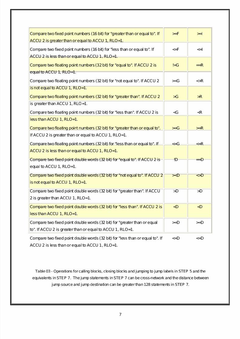
Compare two fixed point numbers (16 bit) for "greater than or equal to". If
ACCU 2 is greater than or equal to ACCU 1, RLO=1.
>=F >=I
Compare two fixed point numbers (16 bit) for "less than or equal to". If
ACCU 2 is less than or equal to ACCU 1, RLO=1.
<=F <=I
Compare two floating point numbers (32bit) for "equal to". If ACCU 2 is
equal to ACCU 1, RLO=1.
!=G ==R
Compare two floating point numbers (32 bit) for "not equal to". If ACCU 2
is not equal to ACCU 1, RLO=1.
><G <>R
Compare two floating point numbers (32 bit) for "greater than". If ACCU 2
is greater than ACCU 1, RLO=1.
>G >R
Compare two floating point numbers (32 bit) for "less than". If ACCU 2 is
less than ACCU 1, RLO=1.
<G <R
Compare two floating point numbers (32 bit) for "greater than or equal to".
If ACCU 2 is greater than or equal to ACCU 1, RLO=1.
>=G >=R
Compare two floating point numbers (32 bit) for "less than or equal to". If
ACCU 2 is less than or equal to ACCU 1, RLO=1.
<=G <=R
Compare two fixed point double words (32 bit) for "equal to". If ACCU 2 is
equal to ACCU 1, RLO=1.
!D ==D
Compare two fixed point double words (32 bit) for "not equal to". If ACCU 2
is not equal to ACCU 1, RLO=1.
><D <>D
Compare two fixed point double words (32 bit) for "greater than". If ACCU
2 is greater than ACCU 1, RLO=1.
>D >D
Compare two fixed point double words (32 bit) for "less than". If ACCU 2 is
less than ACCU 1, RLO=1.
<D <D
Compare two fixed point double words (32 bit) for "greater than or equal
to". If ACCU 2 is greater than or equal to ACCU 1, RLO=1.
>=D >=D
Compare two fixed point double words (32 bit) for "less than or equal to". If ACCU 2 is less than or equal to ACCU 1, RLO=1.
<=D <=D
Table 03 - Operations for calling blocks, closing blocks and jumping to jump labels in STEP 5 and the
equivalents in STEP 7. The jump statements in STEP 7 can be cross-network and the distance between
jump source and jump destination can be greater than 128 statements in STEP 7.

8/16/2019 S5 to S7 Conversion Tips V1
http://slidepdf.com/reader/full/s5-to-s7-conversion-tips-v1 8/24
8
Function description Operations in STL
STEP 5 STEP 7
Absolute block call. SPA <Operand> CALL <Operand>
Conditional block call (RLO=1). U <Operand>SPB <Operand>
U <Operand>SPBNB <jump label>
CALL <Operand>
Absolute block termination. BEA BEA
Conditional block termination
(RLO=1).
BEB BEB
Block termination (completion of a
block)
BE BE
J ump to jump label. SPB =M001
(max. 128 statements in one
network).
SPB M001
(cross-network, no
limits)
Define jump label (max. 4 characters). M001: NOP 0 M001: NOP 0
Table 04 - Arithmetic operations in STEP 5 and the equivalents in STEP 7.
Function description Operations in STL
STEP 5 STEP 7
Add two fixed point numbers (16 Bit): ACCU 2 +ACCU 1 +F +I
Subtract two fixed point numbers (16 Bit): ACCU 2 - ACCU 1 -F -I
Multiply two fixed point numbers (16 Bit): ACCU 2 * ACCU 1 xF *I
Divide two fixed point numbers (16 Bit): ACCU 2 / ACCU 1 :F /I
Add two floating pointnumbers (32Bit): ACCU 2+ACCU 1 +G +R
Subtract two floating pointnumbers (32 Bit): ACCU 2 - ACCU 1 -G -R
Multiply two floating pointnumbers (32 Bit): ACCU 2 *ACCU 1 xG *R
Divide two floating pointnumbers (32Bit): ACCU 2 / ACCU 1 :G /R
Add two fixed point numbers (32 Bit): ACCU 2 +ACCU 1 +D +D
Subtract two fixed point numbers (32 Bit): ACCU 2 - ACCU 1 -D -D
Multiply two fixed pointnumbers (32Bit): ACCU 2 *ACCU 1 xD *D
Divide two fixed point numbers (32 Bit): ACCU 2 / ACCU 1 :D /D

8/16/2019 S5 to S7 Conversion Tips V1
http://slidepdf.com/reader/full/s5-to-s7-conversion-tips-v1 9/24
9
5. COUNTERS
The following table lists the command sequences for counters under STEP 5 and their equivalents in
STEP7
STEP5 STEP7
Operation Operand Operation Operation
Pure up
counter
A I 2.2 A I 2.2
CU C 6 CU C 6
A I 2.5 A I 2.5
R C 6 R C 6
Up counter,
down counter
and counter
delete
A I2.2 A I2.2
CU C 6 CU C 6
A I 2.3 A I 2.3
CD C 6 CD C 6
A I 2.4 A I 2.4
L KC 4 L C#4S C 6 S C 6
A I 2.5 A I 2.5
R C 6 R C 6
Preset
counter to
value
A I 2.7 A I 2.7
L KC 6 L C#6
S C 6 S C 6
(KC = (C=
1 to 999) 1 to 999 )
Query
counter bit
A C 6 A C 6
(is "1" if counter is
not equal to zero)
(is "1" if counter
is notequal to
zero)
Load current
counter value
L C 6 L C 6

8/16/2019 S5 to S7 Conversion Tips V1
http://slidepdf.com/reader/full/s5-to-s7-conversion-tips-v1 10/24
10
(S5: binary, T FW 30 T MW 30
S7: integer)
Load current
counter value
LD C 6 LC C 6
(BCD) T FW32 T MW32
6. TIMERS
The S5TIME data type is stored in binary-coded decimal format (BCD). When you are working with
the S5TIME data type, you define a time value in the range from0 to 999 and a time base.
The time base indicates the interval with which a time decrements the time value by "1" until the timevalue "0" is reached.
Binary structure of the S5TIME data type
15 14 13 12 11 10 9 8 7 6 5 4 3 2 1 0
X X b b a3 a3 a3 a3 a2 a2 a2 a2 a1 a1 a1 a1
X =Irrelevant: these bits are ignoredwhen the time is started.
B =Time base (see table below)
a1-a3 =Time value in the binary-coded decimal format (BCD)
Time base for data of the S5TIME data type
Time base Binary code Possible range
10 ms 00 10 ms - 9 s 990 ms100 ms 01 100 ms - 1 min 39 s 990 ms
1 s 10 1 s - 16 min 39 s
10 s 11 10 s - 2 hr 46 min 30 s

8/16/2019 S5 to S7 Conversion Tips V1
http://slidepdf.com/reader/full/s5-to-s7-conversion-tips-v1 11/24
11
7. LINKING OPERATIONS
The following table lists the operands in STEP 5 and their STEP 7 equivalents.
Operand area in STEP5 Operand area in STEP7
FW Flag word word MW Bit memory word
IW Input word IW Input word
QW Output word QW Output word
DW Data word from a
data block
DB_ Data from the
global data block
(DBW,DBD)
DI_ Data word from an
instance data
block (DIW,DID)
IN Input parameter of
an FC or FB
IN_OUT Through
parameter of an
FC or FB
OUT Outputparameter
of an FC or FB
L Temporary
variable, local
data
DIX Static variable of
an FB

8/16/2019 S5 to S7 Conversion Tips V1
http://slidepdf.com/reader/full/s5-to-s7-conversion-tips-v1 12/24
12
The following table lists the linking operations in STEP 5 and their STEP 7 equivalents.
STEP 5 STEP 7
Operation Operand Operation Operand
Link words
with AND,
OR and
EXCLUSIVE
OR
L IN1 L IN10
L IN1 L IN20
AW OW
XOW
AW
T OUT T OUT
L IN1 L IN10
L IN1 L IN20
OW OW
T OUT T OUT
L IN1 L IN10
L IN1 L IN20
XOW XOW
T OUT T OUT
IN1,IN1= IN10,IN20=
IW,QW,FW,DW,KF,KM,KH IW,QW,MW,DW,IN,
IN_OUT,constant
OUT=
QW,FW,DW OUT=
QW,MW,DDW,DIW,OUT,
IN_OUT
Link double-
words
Not
possible
L IN30
L IN40

8/16/2019 S5 to S7 Conversion Tips V1
http://slidepdf.com/reader/full/s5-to-s7-conversion-tips-v1 13/24
13
with AND,
OR and
EXCLUSIVE
OR
AD
T OUT
L IN30
L IN40
OD
T OUT
L IN30
L IN40
XOD
T OUT
IN30,IN40=
ID,QD,MD,DBD,DID,
IN,IN_OUT,constant
OUT=
QW,MW,DDD,DID,OUT,
IN_OUT
8. CONVERSION OF STRINGS
The converter thatis part of the Basic Package, converts the data formats of the STEP5 program
correctly. The word-oriented DB in STEP5 is converted into a byte-oriented DB in STEP7. String data
types (STEP5 type 'KC' or 'C') are stored differently in STEP7. The first two bytes contain a length
code. A converted program block doesn't take this code into accountand accesses incorrectly, i.e.
offsetby2 bytes.
In the S5, with absolute addressing, the data is accessed in a DB. When converting to S/ this cannot
be converted automatically. Therefore, after conversion, you mustadjust the appropriate program
settings manually in S7.

8/16/2019 S5 to S7 Conversion Tips V1
http://slidepdf.com/reader/full/s5-to-s7-conversion-tips-v1 14/24
14
9. CONVERSION OF BLOCKS
STEP 7 includes a S5/S7 converter which can be used to convert S5 to S7 programs as complete as
possible. This converter has certain particularities:
Converting special commands for CPUs of the SIMATIC S5 135U and SIMATIC S5 155U
series is notpossible.
This applies to access to the area systemdata of the CPU (e.g.: L BS 0..255 / T BS 0..255).
The modules in the library "S5-S7 Converting Blocks" (visible in the SIMATIC Manager
with File >Open >Libraries in "Standard Library") are intended only for conversions of
existing S5 programs to S7 programs. They cannotbe used in newly created S7 programs.
This STEP 7 libraryoffers the following standard solutions:
Functions of floating point arithmetic:
Name Explanation Number
GP_ADD Add floating point numbers FC 63
GP_DIV Divide floating point numbers FC 66
GP_FPGP Change fixedpoint number to floating point number FC 61
GP_GPFP Change floating point number to fixed point number FC 62GP_MUL Multiply floating point number FC 65
GP_SUB Subtract floating point numbers FC 64
GP_VGL Compare floating point numbers FC 67
RAD_GP Extract rootof floating pointnumbers FC 68
Signal functions:
Name Explanation Number
MLD_ED Message of firstvalue with double flashing light,
bitwise, A
FC 76
MLD_EDK Message of first value with double flashing light,
bitwise, A+M
FC 80
MLD_EDW Message of first value with double flashing light,
wordwise, A
FC 72
MLD_EDWK Message of firstvalue with double flashing light, FC 78

8/16/2019 S5 to S7 Conversion Tips V1
http://slidepdf.com/reader/full/s5-to-s7-conversion-tips-v1 15/24
15
wordwise, A+M
MLD_EZ Message of firstvalue with single flashing light,
bitwise, A
FC 75
MLD_EZK Message of firstvalue with single flashing light,bitwise, A+M
FC 79
MLD_EZW Message of first value with single flashing light,
wordwise, A
FC 71
MLD_EZWK Message of first value with single flashing light,
wordwise, A+M
FC 77
MLD_SAM Collected message, bitwise FC 74
MLD_SAMW Collected message, wordwise (sound alert) FC 73
MLD_TG Clock generator FC 69
MLD_TGZ Clock generator (timing element) FC 70
Integrated functions:
Name Explanation Number
COD_B4 Change BCDnumber to 16 bitdual number FC 81
COD_16 Change 16 bitdual number to BCDnumber FC 82MUL_16 Multiply 16 bit dual numbers FC 83
DIV_16 Divide 16 bit dual numbers FC 84
Calculating functions:
Name Explanation Number
ADD_32 Add 32 bit dual numbers FC 85
DIV_32 Divide 32 bit dual numbers FC 88
MUL_32 Multiply 32 bit dual numbers FC 87
RAD_16 Extract roots of 16 bit dual numbers FC 89
SUB_32 Subtract 32 bit dual numbers FC 86
Registry functions:
Name Explanation Number
REG_FIFO Buffer memory (FIFO) FC 92

8/16/2019 S5 to S7 Conversion Tips V1
http://slidepdf.com/reader/full/s5-to-s7-conversion-tips-v1 16/24
16
REG_LIFO Stack register (LIFO) FC 93
REG_SCHB Bi-directional shiftregister, bitwise FC 90
REG_SCHW Bi-directional shiftregister, wordwise FC 91
Copying data areas:
Name Explanation Number
DB_COPY1 Copy data block, directassignment of parameters FC 94
DB_COPY2 Copy data block, indirectassignment of
parameterization
FC 95
Special functions:
Name Explanation Number
LADEN Load scratchpad memory FC 97
RETTEN Save scratchpad memory FC 96
COD_B8 Change BCD number to 32 bitdual number FC 98
COD_32 Change 32 bitdual number to BCDnumber FC 99
Values Read and Write:
Name Explanation Number
AE_460_1 Read analog value FC 100
AE_460_2 Read analog value FC 101
AE_463_1 Read analog value FC 102
AE_463_2 Read analog value FC 103
AE_464_1 Read analog value FC 104AE_464_2 Read analog value FC 105
AE_466_1 Read analog value FC 106
AE_466_2 Read analog value FC 107
PER_ET1 Read and Write for extended periphery (direct
assignmentof parameters)
FC 110
PER_ET2 Read and Write for extended periphery (indirect
assignmentof parameters)
FC 111
RLG_AA1 Output analog value FC 108

8/16/2019 S5 to S7 Conversion Tips V1
http://slidepdf.com/reader/full/s5-to-s7-conversion-tips-v1 17/24
17
RLG_AA2 Output analog value FC 109
Note:
When using the standard functions FC100-FC111, the peripherial addresses are to be observed (see also
online help for these blocks). The refreshment of the process image depends on the S7 CPU. If you assign
a partly peripherial address (between 1 and 8) to the address, these addresses are not taken into account
in the cyclic refreshmentof the process image.
Mathematical functions:
Name Explanation Number
A2_H_A1 AKKU 2 to the power of AKKU 1 FC 125
ARCCOS Arc cosine (x) FC 117ARCCOT Arc cotangens (x) FC 119
ARCSIN Arc sine (x) FC 116
ARCTAN Arc tangent (x) FC 118
B_LOG_X General logarithm Iog (x) to basis b FC 122
COSINUS Cosine (x) FC 113
COTANG Cotangent (x) FC 115
E_H_N e to the power of n FC 123
LG_X Decade logarithm Iog (x) FC 121
LN_X Natural logarithm ln (x) FC 120
SINUS Sine (x) FC 112
TANGENS Tangent (x) FC 114
ZEHN_H_N 10 to the power of n FC 124

8/16/2019 S5 to S7 Conversion Tips V1
http://slidepdf.com/reader/full/s5-to-s7-conversion-tips-v1 18/24
18
10. ANALOG VALUES
If you have replaced the S5 analog modules with S7 analog modules, you can no longer use any standard
blocks, except for the R64 block, because they can only be interconnected directly with the inputs and
outputs of the analog modules. However, since the modules have different resolutions, the standard blockswould run the risk of providing false results.
However, if you have not used any standard interface in the S5 program, you can supplement the existing
program byconverting the analog values.
The S5 modules workby defaultwith a resolution of 2048units - however, the S7 modules have a normal
resolution of 27648 units (S7 format).
You must take this change in resolution into consideration in the the S5 programso as not to falsify the
result of the evaluation.
The diagrambelowclearly shows the interrelationships.
Fig. 1: Overview
diagramof
values
transferred
between the
groups
Definition of tags:
a =Output value of S5 analog input module
b =Output value of S5 processing
c =Output value after analog output module
d =Output value of S7 analog input module
e =Converted value for output to S7 analog output module
X =Units (resolution) of S5 analog module
Y =Units (resolution) of S7 analog module

8/16/2019 S5 to S7 Conversion Tips V1
http://slidepdf.com/reader/full/s5-to-s7-conversion-tips-v1 19/24
19
If you use an S5 standard interface with a resolution of 2048 units, the following conversion factor applies:
Formula 1: Conversion of output values fromthe S7 input module
The values determined in the S5 controller must also be converted for the analog output. The output
modules of the S5 series have a default resolution of 1024 units. In this context, therefore, the conversion
formula is:
Formula 2: Conversion of output values of old S5 program
Some S5 interfaces do not workwith 2048/1024units, for example when using the R64 block. This block
uses a resolution of 16384 units. In general, the following two formulas apply for converting analog value:
Formula 3: General formula for converting output values fromthe S7 inputmodule
Formula 4: General formula for converting the old S5 program
Note
When using a 4-20 mA interface, you cannot change the formatbecause S7 modules do not cause a shift
of 512 units.
A special example shows the conversion clearly.
Example
You replace an S5 analog input module AE460 with an ET 200S. Furthermore, you replace the S5 analog
output module with an S7 module. In the S5 programyou use the evaluation with the R64 block. To be able
to continue using the calculation with the existing program, before processing the analog value in the S5
controller, you have to convert the new input signal.
Now you can no longer connect the analog values directly with the input of the R64 block. The value from
the analog module has to be converted with a factor (this factor cannotbe setwith the COM REGparameter) and has to be preset on the block as R64analog format. Once the output values have been

8/16/2019 S5 to S7 Conversion Tips V1
http://slidepdf.com/reader/full/s5-to-s7-conversion-tips-v1 20/24
20
calculated bythe R64 block, you must once again convert the R64 analog formatvalues with a factor and
then output them to the S7 analog output module.
As described above, the R64 block works with a resolution of 16384 units (analog format). Therefore you
have to recalculate the conversion factor. The combination of formulas 3 and 4 applies.
Formula 5: Conversion for output values of the S7 module when using the R64 block
Formula 6: Conversion for output values of the S5 controller

8/16/2019 S5 to S7 Conversion Tips V1
http://slidepdf.com/reader/full/s5-to-s7-conversion-tips-v1 21/24
21
11. BIT BYTE INDIRECT ADDRESSING
When calculating the address in STEP 5, bits 12 to 15 are used for the interimresults. But these bits are
notneeded for indirect addressing in STEP 5. Unlike DO instructions (e.g. "B MW") in STEP 5, in STEP 7
addressing is via double-words, because of the extended address area. With the instruction in STEP 7, anarea (E, A, M), an access range (bit, byte, word and double-word) and an address are specified. The
address contains the byte number.
The structure of the address register must be observed when an address is presetvia the Accu:
RRR: area identifier
B...B: byte address
XXX: bit address
Fig. 01
If the program is now converted to STEP 7, then when bits 12 to 15 are used by STEP 7 the system
changes the addresses.
Fig. 01 shows an example of a bit pattern "W#16#221". After conversion, the address "33.2" is calculated.
Fig. 02

8/16/2019 S5 to S7 Conversion Tips V1
http://slidepdf.com/reader/full/s5-to-s7-conversion-tips-v1 22/24
22
Fig. 02 shows the same program, but with the bit pattern"W#16#1221". The leading "1" is not evaluated by
STEP 5. After conversion, however, the address "35.2"is calculated bySTEP 7. The reason for this is that
the leading "1"at the bit point is placed bythe systemin the byte address with value 2.
Fig. 03
Remedy:
If you can't ensure that bits 12 to 15 are not used, then change the two move commands as follows.
SLW 5 to SLW 12.
SRW 5 to SRW 12.
After conversion, however, the correct address "33.2" is calculated in STEP 7.
Fig. 04

8/16/2019 S5 to S7 Conversion Tips V1
http://slidepdf.com/reader/full/s5-to-s7-conversion-tips-v1 23/24
23
12. PID CONTROL PARAMETERS
When converting a control block fromS5 to S7, you need to be aware not all parameters available in the S5, can
be converted to S7.
The parameters in the S5 and the S7 are not identical. In the following two tables parameters are explained.
Parameters S5 Meaning
TI Time constant
TD Derivative time
KP Proportional coefficient
TV Derivative time
TN Reset time
TA Sample time
T1 D component lag
Table 1: Control parameters S5
Parameters S7 Meaning
TI Integral action time (reset time)
Gain Gain (amplification factor)
TD Derivative time
TM_LAG D component lag
Table 2: Control parameters S7
In the following table, you will find conversion of control parameters fromS5 to S7. The conversion factors (1000,
1/1000) for KP; R and TI within OB 251 of the S5 are not included.
Control parameters
Controlling
S5
Controlling
S7
Conversion
S5 ->S7
Remarks
KP x R Gain Gain =KP x R depends on the controller in the S 5
typically R=1
TI =TA :
TN
TI =TN TI(S7) =TA :
TI(S5)
TI and TN are used in the S 5
TD =TV :
TA
TD (S7) =
TV
TD(S7) =
TD(S5) x TA
TD and TA are used in the S5
T1 TM_LAG TM_LAG =1 rarely existing in the S5 (configured to TV : 5)

8/16/2019 S5 to S7 Conversion Tips V1
http://slidepdf.com/reader/full/s5-to-s7-conversion-tips-v1 24/24
Table 3: Conversion of control parameters
After converting an S5 program with a blockcall an error message is issued when compiling the STL
source created with reference to the order of the interconnected parameters:
Error message: Wrong order of parameters for Symbol can lead to permutations/shifts
In S5 the parameters are sorted in the order in which they are used in the program. In S7 the parameters
are sorted according to type in the order IN, OUT, IN_OUT. The converter adopts the actual parameters of
block calls fromthe S5 withoutany changes. Therefore the order of parameters in the STL source is not
correct.
Remedy:
If converted files fromthe S5 program contain block calls in which the order of the actual parameters does
not match the order in the declaration, you can easily correct this byresorting using Cut and Paste. You
must make sure that the actual parameters are sorted in the same way as the declarations of the blocks
called. Then the STL source can be compiled withoutany errors.
The SFC20 block described in the manual "STEP 7 Standard and SystemFunctions" copies the contents
in the reverse order to that of the correspondingblock with S5.
If a program is converted fromS5 to S7, then watch out for the following:
If the source area and the target area overlap, the block cannotbe simply replaced when converting to S7.
The conversion with NOT R... and NOT S... (negation of the VKE) results in having the same value of the
VKE (connection result) after the operation as before the operation. One of the two following "S/R-
commands" is executed in any case, so that the resultwill always be correct. The SET command, however,
changes the VKE and should not be used for this issue.
Converting S5 data to STEP 7 is not possible if the data is on write-protected media (e.g. on a write-
protected floppydisk). In this case copythe S5 data into a writable directory and then convert this project –
copied into the directory – with the S5/S7 converter.
For printing out converted S5 programs it is recommended to choose the "DIN A4 landscape" format. If you
use the "DIN A4 portrait" format, depending on the printer driver used, characters fromthe end of the line
mightbe printed at the beginning of the nextline. By choosing the landscape format your program printouts
will be more legible.