roof assemblies and rooftop structures - home
TRANSCRIPT

2012 SEATTLE BUILDING CODE 363
CHAPTER 15
ROOF ASSEMBLIES AND ROOFTOP STRUCTURES
SECTION 1501GENERAL
1501.1 Scope. The provisions of this chapter shall govern thedesign, materials, construction and quality of roof assemblies,and rooftop structures.
SECTION 1502DEFINITIONS
1502.1 Definitions. The following terms are defined in Chap-ter 2:
AGGREGATE.
BALLAST.
BUILT-UP ROOF COVERING.
INTERLAYMENT.
MECHANICAL EQUIPMENT SCREEN.
METAL ROOF PANEL.
METAL ROOF SHINGLE.
MODIFIED BITUMEN ROOF COVERING.
PENTHOUSE.
PHOTOVOLTAIC MODULES/SHINGLES.
POSITIVE ROOF DRAINAGE.
REROOFING.
ROOF ASSEMBLY.
ROOF COVERING.
ROOF COVERING SYSTEM.
ROOF DECK.
ROOF RECOVER.
ROOF REPAIR.
ROOF REPLACEMENT.
ROOF VENTILATION.
ROOFTOP STRUCTURE.
SCUPPER.
SINGLE-PLY MEMBRANE.
UNDERLAYMENT.
SECTION 1503WEATHER PROTECTION
1503.1 General. Roof decks shall be covered with approvedroof coverings secured to the building or structure in accor-dance with the provisions of this chapter. Roof coveringsshall be designed and installed in accordance with this code
and the approved manufacturer’s instructions such that theroof covering shall serve to protect the building or structure.
1503.2 Flashing. Flashing shall be installed in such a mannerso as to prevent moisture entering the wall and roof throughjoints in copings, through moisture-permeable materials andat intersections with parapet walls and other penetrationsthrough the roof plane.
1503.2.1 Locations. Flashing shall be installed at wall androof intersections, at gutters, wherever there is a change inroof slope or direction and around roof openings. Whereflashing is of metal, the metal shall be corrosion resistantwith a thickness of not less than 0.019 inch (0.483 mm)(No. 26 galvanized sheet).
1503.3 Coping. Parapet walls shall be properly coped withnoncombustible, weatherproof materials of a width no lessthan the thickness of the parapet wall.
[P] 1503.4 Roof drainage. Design and installation of roofdrainage systems shall comply with Section 1503 of this codeand Sections 1106 and 1108, as applicable, of the ((Interna-tional)) Uniform Plumbing Code.
[P] 1503.4.1 Secondary (emergency overflow) drains orscuppers. Where roof drains are required, secondary(emergency overflow) roof drains or scuppers shall be pro-vided where the roof perimeter construction extends abovethe roof in such a manner that water will be entrapped ifthe primary drains allow buildup for any reason. Theinstallation and sizing of secondary emergency overflowdrains, leaders and conductors shall comply with Sections1106 and 1108, as applicable, of the ((International)) Uni-form Plumbing Code.
1503.4.2 Scuppers. When scuppers are used for second-ary (emergency overflow) roof drainage, the quantity,size, location and inlet elevation of the scuppers shall besized to prevent the depth of ponding water from exceed-ing that for which the roof was designed as determined bySection 1611.1. Scuppers shall not have an openingdimension of less than 4 inches (102 mm). The flowthrough the primary system shall not be considered whenlocating and sizing scuppers.
1503.4.3 Gutters. Gutters and leaders placed on the out-side of buildings, other than Group R-3, private garagesand buildings of Type V construction, shall be of noncom-bustible material or a minimum of Schedule 40 plasticpipe.
1503.5 Roof ventilation. Intake and exhaust vents shall beprovided in accordance with Section 1203.2 and the manufac-turer’s installation instructions.
1503.6 Crickets and saddles. A cricket or saddle shall beinstalled on the ridge side of any chimney or penetrationgreater than 30 inches (762 mm) wide as measured perpen-
15_Seattle_Build_2012.fm Page 363 Wednesday, November 13, 2013 8:51 AM

ROOF ASSEMBLIES AND ROOFTOP STRUCTURES
364 2012 SEATTLE BUILDING CODE
dicular to the slope. Cricket or saddle coverings shall be sheetmetal or of the same material as the roof covering.
Exception: Unit skylights installed in accordance withSection 2405.5 and flashed in accordance with the manu-facturer’s instructions shall be permitted to be installedwithout a cricket or saddle.
SECTION 1504PERFORMANCE REQUIREMENTS
1504.1 Wind resistance of roofs. Roof decks and roof cover-ings shall be designed for wind loads in accordance withChapter 16 and Sections 1504.2, 1504.3 and 1504.4.
1504.1.1 Wind resistance of asphalt shingles. Asphaltshingles shall comply with Section 1507.2.7.
1504.2 Wind resistance of clay and concrete tile. Windloads on clay and concrete tile roof coverings shall be inaccordance with Section 1609.5.
1504.3 Wind resistance of nonballasted roofs. Roof cover-ings installed on roofs in accordance with Section 1507 thatare mechanically attached or adhered to the roof deck shall bedesigned to resist the design wind load pressures for compo-nents and cladding in accordance with Section 1609.
1504.3.1 Other roof systems. Roof systems with built-up,modified bitumen, fully adhered or mechanically attachedsingle-ply through fastened metal panel roof systems, andother types of membrane roof coverings shall also betested in accordance with FM 4474, UL 580 or UL 1897.
1504.3.2 Metal panel roof systems. Metal panel roof sys-tems through fastened or standing seam shall be tested inaccordance with UL 580 or ASTM E 1592.
Exception: Metal roofs constructed of cold-formedsteel, where the roof deck acts as the roof covering andprovides both weather protection and support for struc-tural loads, shall be permitted to be designed and testedin accordance with the applicable referenced structuraldesign standard in Section 2210.1.
1504.4 Ballasted low-slope roof systems. Ballasted low-slope (roof slope < 2:12) single-ply roof system coveringsinstalled in accordance with Sections 1507.12 and 1507.13shall be designed in accordance with Section 1504.8 andANSI/SPRI RP-4.
1504.5 Edge securement for low-slope roofs. Low-slopebuilt-up, modified bitumen and single-ply roof system metaledge securement, except gutters, shall be designed andinstalled for wind loads in accordance with Chapter 16 andtested for resistance in accordance with Test Methods RE-1,RE-2 and RE-3 of ANSI/SPRI ES-1, except Vult wind speedshall be determined from Figure 1609A, 1609B, or 1609C asapplicable.
1504.6 Physical properties. Roof coverings installed onlow-slope roofs (roof slope < 2:12) in accordance with Sec-tion 1507 shall demonstrate physical integrity over the work-ing life of the roof based upon 2,000 hours of exposure toaccelerated weathering tests conducted in accordance with
ASTM G 152, ASTM G 155 or ASTM G 154. Those roofcoverings that are subject to cyclical flexural response due towind loads shall not demonstrate any significant loss of ten-sile strength for unreinforced membranes or breakingstrength for reinforced membranes when tested as hereinrequired.
1504.7 Impact resistance. Roof coverings installed on low-slope roofs (roof slope < 2:12) in accordance with Section1507 shall resist impact damage based on the results of testsconducted in accordance with ASTM D 3746, ASTM D4272, CGSB 37-GP-52M or the “Resistance to Foot TrafficTest” in Section 5.5 of FM 4470.
1504.8 Aggregate. Aggregate used as surfacing for roof cov-erings and aggregate, gravel or stone used as ballast shall notbe used on the roof of a building located in a hurricane-proneregion as defined in Section 202, or on any other buildingwith a mean roof height exceeding that permitted by Table1504.8 based on the exposure category and basic wind speedat the site.
TABLE 1504.8MAXIMUM ALLOWABLE MEAN ROOF HEIGHT PERMITTED
FOR BUILDINGS WITH AGGREGATE ON THE ROOF INAREAS OUTSIDE A HURRICANE-PRONE REGION
For SI: 1 foot = 304.8 mm; 1 mile per hour = 0.447 m/s.a. Mean roof height as defined in ASCE 7.b. For intermediate values of Vasd, the height associated with the next higher
value of Vasd shall be used, or direct interpolation is permitted.c. NP = gravel and stone not permitted for any roof height.d. Vasd shall be determined in accordance with Section 1609.3.1.
SECTION 1505FIRE CLASSIFICATION
1505.1 General. Roof assemblies shall be divided into theclasses defined below. Class A, B and C roof assemblies androof coverings required to be listed by this section shall betested in accordance with ASTM E 108 or UL 790. In addi-tion, fire-retardant-treated wood roof coverings shall betested in accordance with ASTM D 2898. The minimum roofcoverings installed on buildings shall comply with Table1505.1 based on the type of construction of the building.
Exception: Skylights and sloped glazing that comply withChapter 24 or Section 2610.
NOMINAL DESIGN WIND SPEED, Vasd (mph)b, d
MAXIMUM MEAN ROOF HEIGHT (ft)a, c
Exposure category
B C D
85 170 60 30
90 110 35 15
95 75 20 NP
100 55 15 NP
105 40 NP NP
110 30 NP NP
115 20 NP NP
120 15 NP NP
Greater than 120 NP NP NP
15_Seattle_Build_2012.fm Page 364 Wednesday, November 13, 2013 8:51 AM
ROOF ASSEMBLIES AND ROOFTOP STRUCTURES
2012 SEATTLE BUILDING CODE 365
1505.2 Class A roof assemblies. Class A roof assemblies arethose that are effective against severe fire test exposure. ClassA roof assemblies and roof coverings shall be listed and iden-tified as Class A by an approved testing agency. Class A roofassemblies shall be permitted for use in buildings or struc-tures of all types of construction.
Exceptions:
1. Class A roof assemblies include those with cover-ings of brick, masonry or an exposed concrete roofdeck.
2. Class A roof assemblies also include ferrous or cop-per shingles or sheets, metal sheets and shingles,clay or concrete roof tile or slate installed on non-combustible decks or ferrous, copper or metal sheetsinstalled without a roof deck on noncombustibleframing.
3. Class A roof assemblies include minimum 16 oz/sq.ft. (0.0416 kg/m2) copper sheets installed over com-bustible decks.
1505.3 Class B roof assemblies. Class B roof assemblies arethose that are effective against moderate fire-test exposure.Class B roof assemblies and roof coverings shall be listed andidentified as Class B by an approved testing agency.
1505.4 Class C roof assemblies. Class C roof assemblies arethose that are effective against light fire-test exposure. ClassC roof assemblies and roof coverings shall be listed and iden-tified as Class C by an approved testing agency.
1505.5 Nonclassified roofing. Nonclassified roofing isapproved material that is not listed as a Class A, B or C roofcovering.
1505.6 Fire-retardant-treated wood shingles and shakes.Fire-retardant-treated wood shakes and shingles shall betreated by impregnation with chemicals by the full-cell vac-uum-pressure process, in accordance with AWPA C1. Eachbundle shall be marked to identify the manufactured unit andthe manufacturer, and shall also be labeled to identify theclassification of the material in accordance with the testing
required in Section 1505.1, the treating company and thequality control agency.
1505.7 Special purpose roofs. Special purpose wood shingleor wood shake roofing shall conform with the grading andapplication requirements of Section 1507.8 or 1507.9. Inaddition, an underlayment of 5/8-inch (15.9 mm) Type Xwater-resistant gypsum backing board or gypsum sheathingshall be placed under minimum nominal 1/2-inch-thick (12.7mm) wood structural panel solid sheathing or 1-inch (25 mm)nominal spaced sheathing.
1505.8 Photovoltaic systems. Rooftop installed photovoltaicsystems that are adhered or attached to the roof covering orphotovoltaic modules/shingles installed as roof coveringsshall be labeled to identify their fire classification in accor-dance with the testing required in Section 1505.1.
SECTION 1506MATERIALS
1506.1 Scope. The requirements set forth in this section shallapply to the application of roof-covering materials specifiedherein. Roof coverings shall be applied in accordance withthis chapter and the manufacturer’s installation instructions.Installation of roof coverings shall comply with the applica-ble provisions of Section 1507.
1506.2 Compatibility of materials. Roofs and roof cover-ings shall be of materials that are compatible with each otherand with the building or structure to which the materials areapplied.
1506.3 Material specifications and physical characteris-tics. Roof-covering materials shall conform to the applicablestandards listed in this chapter. In the absence of applicablestandards or where materials are of questionable suitability,testing by an approved agency shall be required by the build-ing code official to determine the character, quality and limi-tations of application of the materials.
1506.4 Product identification. Roof-covering materialsshall be delivered in packages bearing the manufacturer’sidentifying marks and approved testing agency labelsrequired in accordance with Section 1505. Bulk shipments ofmaterials shall be accompanied with the same informationissued in the form of a certificate or on a bill of lading by themanufacturer.
SECTION 1507REQUIREMENTS FOR ROOF COVERINGS
1507.1 Scope. Roof coverings shall be applied in accordancewith the applicable provisions of this section and the manu-facturer's installation instructions.
1507.2 Asphalt shingles. The installation of asphalt shinglesshall comply with the provisions of this section.
1507.2.1 Deck requirements. Asphalt shingles shall befastened to solidly sheathed decks.
1507.2.2 Slope. Asphalt shingles shall only be used onroof slopes of two units vertical in 12 units horizontal (17-percent slope) or greater. For roof slopes from two units
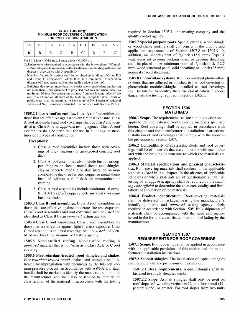
TABLE 1505.1((a,))b
MINIMUM ROOF COVERING CLASSIFICATION FOR TYPES OF CONSTRUCTION
For SI: 1 foot = 304.8 mm, 1 square foot = 0.0929 m2.((a.Unless otherwise required in accordance with the International Wildland-
Urban Interface Code or due to the location of the building within a firedistrict in accordance with Appendix D.))
b. Nonclassified roof coverings shall be permitted on buildings of Group R-3and Group U occupancies, where there is a minimum fire-separationdistance of 6 feet measured from the leading edge of the roof.
c. Buildings that are not more than two stories above grade plane and havingnot more than 6,000 square feet of projected roof area and where there is aminimum 10-foot fire-separation distance from the leading edge of theroof to a lot line on all sides of the building, except for street fronts orpublic ways, shall be permitted to have roofs of No. 1 cedar or redwoodshakes and No. 1 shingles constructed in accordance with Section 1505.7.
IA IB IIA IIB IIIA IIIB IV VA VB
B B B Cc B Cc B B Cc
15_Seattle_Build_2012.fm Page 365 Wednesday, November 13, 2013 8:51 AM

ROOF ASSEMBLIES AND ROOFTOP STRUCTURES
366 2012 SEATTLE BUILDING CODE
vertical in 12 units horizontal (17-percent slope) up to fourunits vertical in 12 units horizontal (33-percent slope),double underlayment application is required in accordancewith Section 1507.2.8.
1507.2.3 Underlayment. Unless otherwise noted,required underlayment shall conform to ASTM D 226,Type I, ASTM D 4869, Type I, or ASTM D 6757.
1507.2.4 Self-adhering polymer modified bitumensheet. Self-adhering polymer modified bitumen sheet shallcomply with ASTM D 1970.
1507.2.5 Asphalt shingles. Asphalt shingles shall complywith ASTM D 225 or ASTM D 3462.
1507.2.6 Fasteners. Fasteners for asphalt shingles shall begalvanized, stainless steel, aluminum or copper roofingnails, minimum 12 gage [0.105 inch (2.67 mm)] shankwith a minimum 3/8 inch-diameter (9.5 mm) head, of alength to penetrate through the roofing materials and aminimum of 3/4 inch (19.1 mm) into the roof sheathing.Where the roof sheathing is less than 3/4 inch (19.1 mm)thick, the nails shall penetrate through the sheathing. Fas-teners shall comply with ASTM F 1667.
1507.2.7 Attachment. Asphalt shingles shall have theminimum number of fasteners required by the manufac-turer, but not less than four fasteners per strip shingle ortwo fasteners per individual shingle. Where the roof slopeexceeds 21 units vertical in 12 units horizontal (21:12),shingles shall be installed as required by the manufacturer.
1507.2.7.1 Wind resistance. Asphalt shingles shall betested in accordance with ASTM D 7158. Asphalt shin-gles shall meet the classification requirements of Table1507.2.7.1(1) for the appropriate maximum basic windspeed. Asphalt shingle packaging shall bear a label toindicate compliance with ASTM D 7158 and therequired classification in Table 1507.2.7.1(1).
Exception: Asphalt shingles not included in thescope of ASTM D 7158 shall be tested and labeledto indicate compliance with ASTM D 3161 and therequired classification in Table 1507.2.7.1(2).
TABLE 1507.2.7.1(1)CLASSIFICATION OF ASPHALT
ROOF SHINGLES PER ASTM D 7158a
For SI: 1 foot = 304.8 mm; 1 mph = 0.447 m/s.a. The standard calculations contained in ASTM D 7158 assume exposure
category B or C and building height of 60 feet or less. Additionalcalculations are required for conditions outside of these assumptions.
b. Vasd shall be determined in accordance with Section 1609.3.1.
TABLE 1507.2.7.1(2)CLASSIFICATION OF ASPHALT SHINGLES PER ASTM D 3161
For SI: 1 mph = 0.447 m/s.
a. Vasd shall be determined in accordance with Section 1609.3.1.
1507.2.8 Underlayment application. For roof slopesfrom two units vertical in 12 units horizontal (17-percentslope) and up to four units vertical in 12 units horizontal(33-percent slope), underlayment shall be two layersapplied in the following manner. Apply a minimum 19-inch-wide (483 mm) strip of underlayment felt parallelwith and starting at the eaves, fastened sufficiently to holdin place. Starting at the eave, apply 36-inch-wide (914mm) sheets of underlayment overlapping successivesheets 19 inches (483 mm), by fastened sufficiently tohold in place. Distortions in the underlayment shall notinterfere with the ability of the shingles to seal. For roofslopes of four units vertical in 12 units horizontal (33-per-cent slope) or greater, underlayment shall be one layerapplied in the following manner. Underlayment shall beapplied shingle fashion, parallel to and starting from theeave and lapped 2 inches (51 mm), fastened sufficiently tohold in place. Distortions in the underlayment shall notinterfere with the ability of the shingles to seal.
1507.2.8.1 High wind attachment. Underlaymentapplied in areas subject to high winds [Vasd greater than110 mph (49 m/s) as determined in accordance withSection 1609.3.1] shall be applied with corrosion-resis-tant fasteners in accordance with the manufacturer'sinstructions. Fasteners are to be applied along the over-lap at a maximum spacing of 36 inches (914 mm) oncenter.
Underlayment installed where Vasd, in accordancewith Section 1609.3.1, equals or exceeds 120 mph (54m/s) shall comply with ASTM D 226 Type II, ASTM D4869 Type IV, or ASTM D 6757. The underlaymentshall be attached in a grid pattern of 12 inches (305 mm)between side laps with a 6-inch (152 mm) spacing at theside laps. Underlayment shall be applied in accordancewith Section 1507.2.8 except all laps shall be a mini-mum of 4 inches (102 mm). Underlayment shall beattached using metal or plastic cap nails with a headdiameter of not less than 1 inch (25 mm) with a thicknessof at least 32-gauge [0.0134 inch (0.34 mm)] sheetmetal. The cap nail shank shall be a minimum of 12gauge [0.105 inch (2.67 mm)] with a length to penetrate
NOMINAL DESIGNWIND SPEED, Vasd
b (mph)CLASSIFICATIONREQUIREMENT
85 D, G or H
90 D, G or H
100 G or H
110 G or H
120 G or H
130 H
140 H
150 H
NOMINAL DESIGNWIND SPEED, Vasd
a (mph)CLASSIFICATIONREQUIREMENT
85 A, D or F
90 A, D or F
100 A, D or F
110 F
120 F
130 F
140 F
150 F
15_Seattle_Build_2012.fm Page 366 Wednesday, November 13, 2013 8:51 AM
ROOF ASSEMBLIES AND ROOFTOP STRUCTURES
2012 SEATTLE BUILDING CODE 367
through the roof sheathing or a minimum of 3/4 inch(19.1 mm) into the roof sheathing.
Exception: As an alternative, adhered underlaymentcomplying with ASTM D 1970 shall be permitted.
1507.2.8.2 Ice barrier. In areas where there has been ahistory of ice forming along the eaves causing a backupof water, an ice barrier that consists of at least two lay-ers of underlayment cemented together or of a self-adhering polymer modified bitumen sheet shall be usedin lieu of normal underlayment and extend from thelowest edges of all roof surfaces to a point at least 24inches (610 mm) inside the exterior wall line of thebuilding.
Exception: Detached accessory structures that con-tain no conditioned floor area.
1507.2.9 Flashings. Flashing for asphalt shingles shallcomply with this section. Flashing shall be applied inaccordance with this section and the asphalt shingle manu-facturer’s printed instructions.
1507.2.9.1 Base and cap flashing. Base and cap flash-ing shall be installed in accordance with the manufac-turer’s instructions. Base flashing shall be of eithercorrosion-resistant metal of minimum nominal 0.019-inch (0.483 mm) thickness or mineral-surfaced rollroofing weighing a minimum of 77 pounds per 100square feet (3.76 kg/m2). Cap flashing shall be corro-sion-resistant metal of minimum nominal 0.019-inch(0.483 mm) thickness.
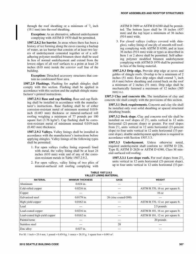
1507.2.9.2 Valleys. Valley linings shall be installed inaccordance with the manufacturer’s instructions beforeapplying shingles. Valley linings of the following typesshall be permitted:
1. For open valleys (valley lining exposed) linedwith metal, the valley lining shall be at least 24inches (610 mm) wide and of any of the corro-sion-resistant metals in Table 1507.2.9.2.
2. For open valleys, valley lining of two plies ofmineral-surfaced roll roofing complying with
ASTM D 3909 or ASTM D 6380 shall be permit-ted. The bottom layer shall be 18 inches (457mm) and the top layer a minimum of 36 inches(914 mm) wide.
3. For closed valleys (valleys covered with shin-gles), valley lining of one ply of smooth roll roof-ing complying with ASTM D 6380, and at least36 inches (914 mm) wide or types as described inItem 1 or 2 above shall be permitted. Self-adher-ing polymer modified bitumen underlaymentcomplying with ASTM D 1970 shall be permittedin lieu of the lining material.
1507.2.9.3 Drip edge. Provide drip edge at eaves andgables of shingle roofs. Overlap to be a minimum of 2inches (51 mm). Eave drip edges shall extend 1/4 inch(6.4 mm) below sheathing and extend back on the roofa minimum of 2 inches (51 mm). Drip edge shall bemechanically fastened a maximum of 12 inches (305mm) o.c.
1507.3 Clay and concrete tile. The installation of clay andconcrete tile shall comply with the provisions of this section.
1507.3.1 Deck requirements. Concrete and clay tile shallbe installed only over solid sheathing or spaced structuralsheathing boards.
1507.3.2 Deck slope. Clay and concrete roof tile shall beinstalled on roof slopes of 21/2 units vertical in 12 unitshorizontal (21-percent slope) or greater. For roof slopesfrom 21/2 units vertical in 12 units horizontal (21-percentslope) to four units vertical in 12 units horizontal (33-per-cent slope), double underlayment application is required inaccordance with Section 1507.3.3.
1507.3.3 Underlayment. Unless otherwise noted,required underlayment shall conform to: ASTM D 226,Type II; ASTM D 2626 or ASTM D 6380, Class M min-eral-surfaced roll roofing.
1507.3.3.1 Low-slope roofs. For roof slopes from 21/2
units vertical in 12 units horizontal (21-percent slope),up to four units vertical in 12 units horizontal (33-per-
TABLE 1507.2.9.2 VALLEY LINING MATERIAL
For SI: 1 inch = 25.4 mm, 1 pound = 0.454 kg, 1 ounce = 28.35 g, 1 square foot = 0.093 m2.
MATERIAL MINIMUM THICKNESS GAGE WEIGHT
Aluminum 0.024 in. — —
Cold-rolled copper 0.0216 in. — ASTM B 370, 16 oz. per square ft.
Copper — — 16 oz
Galvanized steel 0.0179 in. 26 (zinc-coated G90) —
High-yield copper 0.0162 in. — ASTM B 370, 12 oz. per square ft.
Lead — — 2.5 pounds
Lead-coated copper 0.0216 in. — ASTM B 101, 16 oz. per square ft.
Lead-coated high-yield copper 0.0162 in. — ASTM B 101, 12 oz. per square ft.
Painted terne — — 20 pounds
Stainless steel — 28 —
Zinc alloy 0.027 in. — —
15_Seattle_Build_2012.fm Page 367 Wednesday, November 13, 2013 8:51 AM
ROOF ASSEMBLIES AND ROOFTOP STRUCTURES
368 2012 SEATTLE BUILDING CODE
cent slope), underlayment shall be a minimum of twolayers applied as follows:
1. Starting at the eave, a 19-inch (483 mm) strip ofunderlayment shall be applied parallel with theeave and fastened sufficiently in place.
2. Starting at the eave, 36-inch-wide (914 mm)strips of underlayment felt shall be applied over-lapping successive sheets 19 inches (483 mm)and fastened sufficiently in place.
1507.3.3.2 High-slope roofs. For roof slopes of fourunits vertical in 12 units horizontal (33-percent slope)or greater, underlayment shall be a minimum of onelayer of underlayment felt applied shingle fashion, par-allel to, and starting from the eaves and lapped 2 inches(51 mm), fastened only as necessary to hold in place.
1507.3.3.3 High wind attachment. Underlaymentapplied in areas subject to high wind [Vasd greater than110 mph (49 m/s) as determined in accordance withSection 1609.3.1] shall be applied with corrosion-resis-tant fasteners in accordance with the manufacturer’sinstallation instructions. Fasteners are to be appliedalong the overlap not farther apart than 36 inches (914mm) on center.
Underlayment installed where Vasd, in accordancewith Section 1609.3.1, equals or exceeds 120 mph (54m/s) shall be attached in a grid pattern of 12 inches(305 mm) between side laps with a 6-inch (152 mm)spacing at the side laps. Underlayment shall be appliedin accordance with Sections 1507.3.3.1 and 1507.3.3.2except all laps shall be a minimum of 4 inches (102mm). Underlayment shall be attached using metal orplastic cap nails with a head diameter of not less than 1inch (25 mm) with a thickness of at least 32-gauge[0.0134 inch (0.34 mm)] sheet metal. The cap nailshank shall be a minimum of 12 gauge [0.105 inch (2.67mm)] with a length to penetrate through the roofsheathing or a minimum of 3/4 inch (19.1 mm) into theroof sheathing.
Exception: As an alternative, adhered underlaymentcomplying with ASTM D 1970 shall be permitted.
1507.3.4 Clay tile. Clay roof tile shall comply with ASTMC 1167.
1507.3.5 Concrete tile. Concrete roof tile shall complywith ASTM C 1492.
1507.3.6 Fasteners. Tile fasteners shall be corrosion resis-tant and not less than 11 gage, 5/16-inch (8.0 mm) head, andof sufficient length to penetrate the deck a minimum of 3/4
inch (19.1 mm) or through the thickness of the deck,whichever is less. Attaching wire for clay or concrete tileshall not be smaller than 0.083 inch (2.1 mm). Perimeterfastening areas include three tile courses but not less than36 inches (914 mm) from either side of hips or ridges andedges of eaves and gable rakes.
1507.3.7 Attachment. Clay and concrete roof tiles shallbe fastened in accordance with Table 1507.3.7.
1507.3.8 Application. Tile shall be applied according tothe manufacturer's installation instructions, based on thefollowing:
1. Climatic conditions.
2. Roof slope.
3. Underlayment system.
4. Type of tile being installed.
1507.3.9 Flashing. At the juncture of the roof vertical sur-faces, flashing and counterflashing shall be provided inaccordance with the manufacturer’s installation instruc-tions, and where of metal, shall not be less than 0.019-inch(0.48 mm) (No. 26 galvanized sheet gage) corrosion-resis-tant metal. The valley flashing shall extend at least 11inches (279 mm) from the centerline each way and have asplash diverter rib not less than 1 inch (25 mm) high at theflow line formed as part of the flashing. Sections of flash-ing shall have an end lap of not less than 4 inches (102mm). For roof slopes of three units vertical in 12 units hor-izontal (25-percent slope) and over, the valley flashingshall have a 36-inch-wide (914 mm) underlayment ofeither one layer of Type I underlayment running the fulllength of the valley, or a self-adhering polymer-modifiedbitumen sheet complying with ASTM D 1970, in additionto other required underlayment. In areas where the averagedaily temperature in January is 25°F (-4°C) or less orwhere there is a possibility of ice forming along the eavescausing a backup of water, the metal valley flashingunderlayment shall be solid cemented to the roofingunderlayment for slopes under seven units vertical in 12units horizontal (58-percent slope) or self-adhering poly-mer-modified bitumen sheet shall be installed.
1507.4 Metal roof panels. The installation of metal roof pan-els shall comply with the provisions of this section.
1507.4.1 Deck requirements. Metal roof panel roof cov-erings shall be applied to a solid or closely fitted deck,except where the roof covering is specifically designed tobe applied to spaced supports.
1507.4.2 Deck slope. Minimum slopes for metal roof pan-els shall comply with the following:
1. The minimum slope for lapped, nonsoldered seammetal roofs without applied lap sealant shall be threeunits vertical in 12 units horizontal (25-percentslope).
2. The minimum slope for lapped, nonsoldered seammetal roofs with applied lap sealant shall be one-halfunit vertical in 12 units horizontal (4-percent slope).Lap sealants shall be applied in accordance with theapproved manufacturer’s installation instructions.
3. The minimum slope for standing seam of roof sys-tems shall be one-quarter unit vertical in 12 unitshorizontal (2-percent slope).
15_Seattle_Build_2012.fm Page 368 Wednesday, November 13, 2013 8:51 AM

ROOF ASSEMBLIES AND ROOFTOP STRUCTURES
2012 SEATTLE BUILDING CODE 369
TABLE 1507.3.7CLAY AND CONCRETE TILE ATTACHMENTa, b, c
For SI: 1 inch = 25.4 mm, 1 foot = 304.8 mm, 1 mile per hour = 0.447 m/s, 1 pound per square foot = 4.882 kg/m2.a. Minimum fastener size. Corrosion-resistant nails not less than No. 11 gage with 5/16-inch head. Fasteners shall be long enough to penetrate into the sheathing
3/4 inch or through the thickness of the sheathing, whichever is less. Attaching wire for clay and concrete tile shall not be smaller than 0.083 inch.b. Snow areas. A minimum of two fasteners per tile are required or battens and one fastener.c. Roof slopes greater than 24:12. The nose of all tiles shall be securely fastened.d. Horizontal battens. Battens shall be not less than 1 inch by 2 inch nominal. Provisions shall be made for drainage by a minimum of 1/8-inch riser at each nail
or by 4-foot-long battens with at least a 1/2-inch separation between battens. Horizontal battens are required for slopes over 7:12.e. Perimeter fastening areas include three tile courses but not less than 36 inches from either side of hips or ridges and edges of eaves and gable rakes. f. Vasd shall be determined in accordance with Section 1609.3.1.
GENERAL - CLAY OR CONCRETE ROOF TILE
Maximum Nominal Design Wind Speed, Vasd
f (mph)Mean roof height
(feet) Roof slope < 3:12 Roof slope 3:12 and over
85 0-60 One fastener per tile. Flat tile without vertical laps, two fas-teners per tile.
Two fasteners per tile. Only one fastener on slopes of 7:12 and less for tiles with installed weight exceeding 7.5 lbs./sq. ft. having a width no greater than 16 inches.100 0-40
100 > 40-60 The head of all tiles shall be nailed. The nose of all eave tiles shall be fastened with approved clips. All rake tiles shall be nailed with two nails. The nose of all ridge, hip and rake tiles shall be set in a bead of roofer’s mastic.
110 0-60 The fastening system shall resist the wind forces in Section 1609.5.3.
120 0-60 The fastening system shall resist the wind forces in Section 1609.5.3.
130 0-60 The fastening system shall resist the wind forces in Section 1609.5.3.
All > 60 The fastening system shall resist the wind forces in Section 1609.5.3.
INTERLOCKING CLAY OR CONCRETE ROOF TILE WITH PROJECTING ANCHOR LUGSd, e
(Installations on spaced/solid sheathing with battens or spaced sheathing)
Maximum Nominal Design Wind Speed, Vasd
f (mph)Mean roof height
(feet) Roof slope < 5:12 Roof slope 5:12 < 12:12 Roof slope12:12 and over
85 0-60 Fasteners are not required. Tiles with installed weight less than 9 lbs./sq. ft. require a minimum of one fastener per tile.
One fastener per tile every other row. All perimeter tiles require one fastener. Tiles with installed weight less than 9 lbs./sq. ft. require a mini-mum of one fastener per tile.
One fastener required for every tile. Tiles with installed weight less than 9 lbs./sq. ft. require a minimum of one fastener per tile. 100 0-40
100 > 40-60 The head of all tiles shall be nailed. The nose of all eave tiles shall be fastened with approved clips. All rake tiles shall be nailed with two nails The nose of all ridge, hip and rake tiles shall be set in a bead of roofer's mastic.
110 0-60 The fastening system shall resist the wind forces in Section 1609.5.3.
120 0-60 The fastening system shall resist the wind forces in Section 1609.5.3.
130 0-60 The fastening system shall resist the wind forces in Section 1609.5.3.
All > 60 The fastening system shall resist the wind forces in Section 1609.5.3.
INTERLOCKING CLAY OR CONCRETE ROOF TILE WITH PROJECTING ANCHOR LUGS(Installations on solid sheathing without battens)
Maximum Nominal Design Wind Speed, Vasd
f (mph)Mean roof height
(feet) All roof slopes
85 0-60 One fastener per tile.
100 0-40 One fastener per tile.
100 > 40-60 The head of all tiles shall be nailed. The nose of all eave tiles shall be fastened with approved clips. All rake tiles shall be nailed with two nails The nose of all ridge, hip and rake tiles shall be set in a bead of roofer’s mastic.
110 0-60 The fastening system shall resist the wind forces in Section 1609.5.3.
120 0-60 The fastening system shall resist the wind forces in Section 1609.5.3.
130 0-60 The fastening system shall resist the wind forces in Section 1609.5.3.
All > 60 The fastening system shall resist the wind forces in Section 1609.5.3.
15_Seattle_Build_2012.fm Page 369 Wednesday, November 13, 2013 8:51 AM

ROOF ASSEMBLIES AND ROOFTOP STRUCTURES
370 2012 SEATTLE BUILDING CODE
1507.4.3 Material standards. Metal-sheet roof coveringsystems that incorporate supporting structural membersshall be designed in accordance with Chapter 22. Metal-sheet roof coverings installed over structural decking shallcomply with Table 1507.4.3(1). The materials used for
metal-sheet roof coverings shall be naturally corrosionresistant or provided with corrosion resistance in accor-dance with the standards and minimum thicknesses shownin Table 1507.4.3(2).
1507.4.4 Attachment. Metal roof panels shall be securedto the supports in accordance with the approved manufac-turer’s fasteners. In the absence of manufacturer recom-mendations, the following fasteners shall be used:
1. Galvanized fasteners shall be used for steel roofs.
2. Copper, brass, bronze, copper alloy or 300 seriesstainless-steel fasteners shall be used for copperroofs.
3. Stainless-steel fasteners are acceptable for all typesof metal roofs.
1507.4.5 Underlayment and high wind. Underlaymentapplied in areas subject to high winds [Vasd greater than110 mph (49 m/s) as determined in accordance with Sec-tion 1609.3.1] shall be applied with corrosion-resistantfasteners in accordance with the manufacturer’s installa-tion instructions. Fasteners are to be applied along theoverlap not farther apart than 36 inches (914 mm) on cen-ter.
Underlayment installed where Vasd, in accordance withSection 1609.3.1, equals or exceeds 120 mph (54 m/s)shall comply with ASTM D 226 Type II, ASTM D 4869Type IV, or ASTM D 1970. The underlayment shall beattached in a grid pattern of 12 inches (305 mm) betweenside laps with a 6-inch (152 mm) spacing at the side laps.Underlayment shall be applied in accordance with themanufacturer’s installation instructions except all lapsshall be a minimum of 4 inches (102 mm). Underlaymentshall be attached using metal or plastic cap nails with ahead diameter of not less than 1 inch (25 mm) with athickness of at least 32-gauge [0.0134 inch (0.34 mm)]sheet metal. The cap nail shank shall be a minimum of 12gauge [0.105 inch (2.67 mm)] with a length to penetratethrough the roof sheathing or a minimum of 3/4 inch (19.1mm) into the roof sheathing.
Exception: As an alternative, adhered underlaymentcomplying with ASTM D 1970 shall be permitted.
1507.5 Metal roof shingles. The installation of metal roofshingles shall comply with the provisions of this section.
1507.5.1 Deck requirements. Metal roof shingles shall beapplied to a solid or closely fitted deck, except where theroof covering is specifically designed to be applied tospaced sheathing.
1507.5.2 Deck slope. Metal roof shingles shall not beinstalled on roof slopes below three units vertical in 12units horizontal (25-percent slope).
1507.5.3 Underlayment. Underlayment shall complywith ASTM D 226, Type I or ASTM D 4869.
1507.5.3.1 Underlayment and high wind. Underlay-ment applied in areas subject to high winds [Vasd greaterthan 110 mph (49 m/s) as determined in accordancewith Section 1609.3.1] shall be applied with corrosion-resistant fasteners in accordance with the manufac-
TABLE 1507.4.3(1)METAL ROOF COVERINGS
For SI: 1 ounce per square foot = 0.305 kg/m2,1 pound per square foot = 4.882 kg/m2,1 inch = 25.4 mm, 1 pound = 0.454 kg.
a. For Group U buildings, the minimum coating thickness for ASTM A 653galvanized steel roofing shall be G-60.
TABLE 1507.4.3(2)MINIMUM CORROSION RESISTANCE
a. Paint systems in accordance with ASTM A 755 shall be applied over steelproducts with corrosion-resistant coatings complying with ASTM A 792,ASTM A 875, ASTM A 463 or ASTM A 653.
ROOFCOVERING TYPE
STANDARD APPLICATION RATE/THICKNESS
Aluminum
ASTM B 209, 0.024 inch minimum thick-ness for roll-formed panels and 0.019 inch minimum thickness for press-formed shingles.
Aluminum-zinc alloy coated steel
ASTM A 792 AZ 50
Cold-rolled copper
ASTM B 370 minimum 16 oz./sq. ft. and 12 oz./sq. ft. high yield copper for metal-sheet roof covering systems: 12 oz./sq. ft. for preformed metal shingle systems.
Copper 16 oz./sq. ft. for metal-sheet roof-covering systems; 12 oz./sq. ft. for preformed metal shingle systems.
Galvanized steel ASTM A 653 G-90 zinc-coateda.
Hard lead 2 lbs./sq. ft.
Lead-coated copper ASTM B 101
Prepainted steel ASTM A 755
Soft lead 3 lbs./sq. ft.
Stainless steel ASTM A 240, 300 Series Alloys
Steel ASTM A 924
Terne and terne-coated stainless
Terne coating of 40 lbs. per double base box, field painted where applicable in accordance with manufacturer’s installa-tion instructions.
Zinc
0.027 inch minimum thickness; 99.995% electrolytic high grade zinc with alloy addi-tives of copper (0.08% - 0.20%), titanium (0.07% - 0.12%) and aluminum (0.015%).
55% Aluminum-zinc alloy coated steel ASTM A 792 AZ 50
5% Aluminum alloy-coated steel ASTM A 875 GF60
Aluminum-coated steel ASTM A 463 T2 65
Galvanized steel ASTM A 653 G-90
Prepainted steel ASTM A 755a
15_Seattle_Build_2012.fm Page 370 Wednesday, November 13, 2013 8:51 AM

ROOF ASSEMBLIES AND ROOFTOP STRUCTURES
2012 SEATTLE BUILDING CODE 371
turer’s installation instructions. Fasteners are to beapplied along the overlap not farther apart than 36inches (914 mm) on center.
Underlayment installed where Vasd, in accordancewith Section 1609.3.1, equals or exceeds 120 mph (54m/s) shall comply with ASTM D 226 Type II or ASTMD 4869 Type IV. The underlayment shall be attachedin a grid pattern of 12 inches (305 mm) between sidelaps with a 6-inch spacing (152 mm) at the side laps.Underlayment shall be applied in accordance with themanufacturer’s installation instructions except all lapsshall be a minimum of 4 inches (102 mm). Underlay-ment shall be attached using metal or plastic cap nailswith a head diameter of not less than 1 inch (25 mm)with a thickness of at least 32-gauge [0.0134 inch (0.34mm)] sheet metal. The cap nail shank shall be a mini-mum of 12 gauge [0.105 inch (2.67 mm)] with a lengthto penetrate through the roof sheathing or a minimumof ¾ inch (19.1 mm) into the roof sheathing.
Exception: As an alternative, adhered underlaymentcomplying with ASTM D 1970 shall be permitted.
1507.5.4 Ice barrier. In areas where there has been a his-tory of ice forming along the eaves causing a backup ofwater, an ice barrier that consists of at least two layers ofunderlayment cemented together or of a self-adheringpolymer-modified bitumen sheet shall be used in lieu ofnormal underlayment and extend from the lowest edges ofall roof surfaces to a point at least 24 inches (610 mm)inside the exterior wall line of the building.
Exception: Detached accessory structures that containno conditioned floor area.
1507.5.5 Material standards. Metal roof shingle roofcoverings shall comply with Table 1507.4.3(1). The mate-rials used for metal-roof shingle roof coverings shall benaturally corrosion resistant or provided with corrosionresistance in accordance with the standards and minimumthicknesses specified in the standards listed in Table1507.4.3(2).
1507.5.6 Attachment. Metal roof shingles shall besecured to the roof in accordance with the approved manu-facturer’s installation instructions.
1507.5.7 Flashing. Roof valley flashing shall be of corro-sion-resistant metal of the same material as the roof cover-ing or shall comply with the standards in Table1507.4.3(1). The valley flashing shall extend at least 8inches (203 mm) from the centerline each way and shallhave a splash diverter rib not less than 3/4 inch (19.1 mm)high at the flow line formed as part of the flashing. Sec-tions of flashing shall have an end lap of not less than 4inches (102 mm). In areas where the average daily temper-ature in January is 25°F (-4°C) or less or where there is apossibility of ice forming along the eaves causing abackup of water, the metal valley flashing shall have a 36-inch-wide (914 mm) underlayment directly under it con-sisting of either one layer of underlayment running the fulllength of the valley or a self-adhering polymer-modifiedbitumen sheet complying with ASTM D 1970, in additionto underlayment required for metal roof shingles. The
metal valley flashing underlayment shall be solidlycemented to the roofing underlayment for roof slopesunder seven units vertical in 12 units horizontal (58-per-cent slope) or self-adhering polymer-modified bitumensheet shall be installed.
1507.6 Mineral-surfaced roll roofing. The installation ofmineral-surfaced roll roofing shall comply with this section.
1507.6.1 Deck requirements. Mineral-surfaced roll roof-ing shall be fastened to solidly sheathed roofs.
1507.6.2 Deck slope. Mineral-surfaced roll roofing shallnot be applied on roof slopes below one unit vertical in 12units horizontal (8-percent slope).
1507.6.3 Underlayment. Underlayment shall complywith ASTM D 226, Type I or ASTM D 4869.
1507.6.3.1 Underlayment and high wind. Underlay-ment applied in areas subject to high winds [Vasd greaterthan 110 mph (49 m/s) as determined in accordancewith Section 1609.3.1] shall be applied with corrosion-resistant fasteners in accordance with the manufac-turer’s installation instructions. Fasteners are to beapplied along the overlap not farther apart than 36inches (914 mm) on center.
Underlayment installed where Vasd, in accordancewith Section 1609.3.1, equals or exceeds 120 mph (54m/s) shall comply with ASTM D 226 Type II. Theunderlayment shall be attached in a grid pattern of 12inches (305 mm) between side laps with a 6-inch (152mm) spacing at the side laps. Underlayment shall beapplied in accordance with the manufacturer’s installa-tion instructions except all laps shall be a minimum of 4inches (102 mm). Underlayment shall be attached usingmetal or plastic cap nails with a head diameter of notless than 1 inch (25 mm) with a thickness of at least 32-gauge [0.0134 inch (0.34 mm)] sheet metal. The capnail shank shall be a minimum of 12 gauge [0.105 inch(2.67 mm)] with a length to penetrate through the roofsheathing or a minimum of 3/4 inch (19.1 mm) into theroof sheathing.
Exception: As an alternative, adhered underlaymentcomplying with ASTM D 1970 shall be permitted.
1507.6.4 Ice barrier. In areas where there has been a his-tory of ice forming along the eaves causing a backup ofwater, an ice barrier that consists of at least two layers ofunderlayment cemented together or of a self-adheringpolymer-modified bitumen sheet shall be used in lieu ofnormal underlayment and extend from the lowest edges ofall roof surfaces to a point at least 24 inches (610 mm)inside the exterior wall line of the building.
Exception: Detached accessory structures that containno conditioned floor area.
1507.6.5 Material standards. Mineral-surfaced roll roof-ing shall conform to ASTM D 3909 or ASTM D 6380.
1507.7 Slate shingles. The installation of slate shingles shallcomply with the provisions of this section.
1507.7.1 Deck requirements. Slate shingles shall be fas-tened to solidly sheathed roofs.
15_Seattle_Build_2012.fm Page 371 Wednesday, November 13, 2013 8:51 AM

ROOF ASSEMBLIES AND ROOFTOP STRUCTURES
372 2012 SEATTLE BUILDING CODE
1507.7.2 Deck slope. Slate shingles shall only be used onslopes of four units vertical in 12 units horizontal (4:12) orgreater.
1507.7.3 Underlayment. Underlayment shall complywith ASTM D 226, Type I or ASTM D 4869.
1507.7.3.1 Underlayment and high wind. Underlay-ment applied in areas subject to high winds [Vasd greaterthan 110 mph (49 m/s) as determined in accordancewith Section 1609.3.1] shall be applied with corrosion-resistant fasteners in accordance with the manufac-turer’s installation instructions. Fasteners are to beapplied along the overlap not farther apart than 36inches (914 mm) on center.
Underlayment installed where Vasd, in accordancewith Section 1609.3.1, equals or exceeds 120 mph (54m/s) shall comply with ASTM D 226 Type II or ASTMD 4869 Type IV. The underlayment shall be attachedin a grid pattern of 12 inches (305 mm) between sidelaps with a 6-inch (152 mm) spacing at the side laps.Underlayment shall be applied in accordance with themanufacturer’s installation instructions except all lapsshall be a minimum of 4 inches (102 mm). Underlay-ment shall be attached using metal or plastic cap nailswith a head diameter of not less than 1 inch (25 mm)with a thickness of at least 32-gauge [0.0134 inch (0.34mm)] sheet metal. The cap nail shank shall be a mini-mum of 12 gauge [0.105 inch (2.67 mm)] with a lengthto penetrate through the roof sheathing or a minimumof 3/4 inch (19.1 mm) into the roof sheathing.
Exception: As an alternative, adhered underlaymentcomplying with ASTM D 1970 shall be permitted.
1507.7.4 Ice barrier. In areas where the average dailytemperature in January is 25°F (-4°C) or less or wherethere is a possibility of ice forming along the eaves caus-ing a backup of water, an ice barrier that consists of atleast two layers of underlayment cemented together or of aself-adhering polymer-modified bitumen sheet shallextend from the lowest edges of all roof surfaces to a pointat least 24 inches (610 mm) inside the exterior wall line ofthe building.
Exception: Detached accessory structures that containno conditioned floor area.
1507.7.5 Material standards. Slate shingles shall complywith ASTM C 406.
1507.7.6 Application. Minimum headlap for slate shin-gles shall be in accordance with Table 1507.7.6. Slateshingles shall be secured to the roof with two fasteners perslate.
TABLE 1507.7.6SLATE SHINGLE HEADLAP
For SI: 1 inch = 25.4 mm.
1507.7.7 Flashing. Flashing and counterflashing shall bemade with sheet metal. Valley flashing shall be a mini-mum of 15 inches (381 mm) wide. Valley and flashingmetal shall be a minimum uncoated thickness of 0.0179-inch (0.455 mm) zinc-coated G90. Chimneys, stucco orbrick walls shall have a minimum of two plies of felt for acap flashing consisting of a 4-inch-wide (102 mm) strip offelt set in plastic cement and extending 1 inch (25 mm)above the first felt and a top coating of plastic cement. Thefelt shall extend over the base flashing 2 inches (51 mm).
1507.8 Wood shingles. The installation of wood shinglesshall comply with the provisions of this section and Table1507.8.
1507.8.1 Deck requirements. Wood shingles shall beinstalled on solid or spaced sheathing. Where spacedsheathing is used, sheathing boards shall not be less than1-inch by 4-inch (25 mm by 102 mm) nominal dimensionsand shall be spaced on centers equal to the weather expo-sure to coincide with the placement of fasteners.
1507.8.1.1 Solid sheathing required. Solid sheathingis required in areas where the average daily temperaturein January is 25°F (-4°C) or less or where there is apossibility of ice forming along the eaves causing abackup of water.
1507.8.2 Deck slope. Wood shingles shall be installed onslopes of three units vertical in 12 units horizontal (25-per-cent slope) or greater.
1507.8.3 Underlayment. Underlayment shall complywith ASTM D 226, Type I or ASTM D 4869.
1507.8.3.1 Underlayment and high wind. Underlay-ment applied in areas subject to high winds [Vasd greaterthan 110 mph (49 m/s) as determined in accordancewith Section 1609.3.1] shall be applied with corrosion-resistant fasteners in accordance with the manufac-turer’s installation instructions. Fasteners are to beapplied along the overlap not farther apart than 36inches (914 mm) on center.
Underlayment installed where Vasd, in accordancewith Section 1609.3.1, equals or exceeds 120 mph (54m/s) shall comply with ASTM D 226 Type II or ASTMD 4869 Type IV. The underlayment shall be attachedin a grid pattern of 12 inches (305 mm) between sidelaps with a 6-inch (152 mm) spacing at the side laps.Underlayment shall be applied in accordance with themanufacturer’s installation instructions except all lapsshall be a minimum of 4 inches (102 mm). Underlay-ment shall be attached using metal or plastic cap nailswith a head diameter of not less than 1 inch (25 mm)with a thickness of at least 32-gauge [0.0134 inch (0.34mm)] sheet metal. The cap nail shank shall be a mini-mum of 12 gauge [0.105 inch (2.67 mm)] with a lengthto penetrate through the roof sheathing or a minimumof 3/4 inch (19.1 mm) into the roof sheathing.
Exception: As an alternative, adhered underlaymentcomplying with ASTM D 1970 shall be permitted.
SLOPE HEADLAP (inches)
4:12 < slope < 8:12 4
8:12 < slope < 20:12 3
slope ≥ 20:12 2
15_Seattle_Build_2012.fm Page 372 Wednesday, November 13, 2013 8:51 AM

ROOF ASSEMBLIES AND ROOFTOP STRUCTURES
2012 SEATTLE BUILDING CODE 373
TABLE 1507.8WOOD SHINGLE AND SHAKE INSTALLATION
For SI: 1 inch = 25.4 mm, °C = [(°F) - 32]/1.8.
ROOF ITEM WOOD SHINGLES WOOD SHAKES
1. Roof slope Wood shingles shall be installed on slopes of three units vertical in 12 units horizontal (3:12) or greater.
Wood shakes shall be installed on slopes of four units vertical in 12 units horizontal (4:12) or greater.
2. Deck requirement
Temperate climate
Shingles shall be applied to roofs with solid or spaced sheathing. Where spaced sheathing is used, sheathing boards shall not be less than 1″ × 4″ nominal dimensions and shall be spaced on center equal to the weather expo-sure to coincide with the placement of fasten-ers.
Shakes shall be applied to roofs with solid or spaced sheathing. Where spaced sheathing is used, sheathing boards shall not be less than 1″ × 4″ nominal dimensions and shall be spaced on center equal to the weather expo-sure to coincide with the placement of fasten-ers. When 1″ × 4″ spaced sheathing is installed at 10 inches, boards must be installed between the sheathing boards.
In areas where the average daily temperature in January is 25°F or less or where there is a possibility of ice forming along the eaves causing a backup of water.
Solid sheathing required. Solid sheathing is required.
3. Interlayment No requirements. Interlayment shall comply with ASTM D 226,
Type 1.
4. Underlayment
Temperate climateUnderlayment shall comply with ASTM D 226, Type 1.
Underlayment shall comply with ASTM D 226, Type 1.
In areas where there is a possibility of ice forming along the eaves causing a backup of water.
An ice barrier that consists of at least two lay-ers of underlayment cemented together or of a self-adhering polymer-modified bitumen sheet shall extend from the eave's edge to a point at least 24 inches inside the exterior wall line of the building.
An ice barrier that consists of at least two lay-ers of underlayment cemented together or of a self-adhering polymer-modified bitumen sheet shall extend from the lowest edges of all roof surfaces to a point at least 24 inches inside the exterior wall line of the building.
5. Application
Attachment
Fasteners for wood shingles shall be hot-dipped galvanized or Type 304 (Type 316 for coastal areas) stainless steel with a minimum penetration of 0.75 inch into the sheathing. For sheathing less than 0.5 inch thick, the fasteners shall extend through the sheathing.
Fasteners for wood shakes shall be hot-dipped galvanized or Type 304 (Type 316 for coastal areas) with a minimum penetration of 0.75 inch into the sheathing. For sheathing less than 0.5 inch thick, the fasteners shall extend through the sheathing.
No. of fasteners Two per shingle. Two per shake.
Exposure Weather exposures shall not exceed those set forth in Table 1507.8.7.
Weather exposures shall not exceed those set forth in Table 1507.9.8.
Method
Shingles shall be laid with a side lap of not less than 1.5 inches between joints in courses, and no two joints in any three adjacent courses shall be in direct alignment. Spacing between shingles shall be 0.25 to 0.375 inch.
Shakes shall be laid with a side lap of not less than 1.5 inches between joints in adjacent courses. Spacing between shakes shall not be less than 0.375 inch or more than 0.625 inch for shakes and taper sawn shakes of naturally durable wood and shall be 0.25 to 0.375 inch for preservative-treated taper sawn shakes.
Flashing In accordance with Section 1507.8.8. In accordance with Section 1507.9.9.
15_Seattle_Build_2012.fm Page 373 Wednesday, November 13, 2013 8:51 AM

ROOF ASSEMBLIES AND ROOFTOP STRUCTURES
374 2012 SEATTLE BUILDING CODE
1507.8.4 Ice barrier. In areas where there has been a his-tory of ice forming along the eaves causing a backup ofwater, an ice barrier that consists of at least two layers ofunderlayment cemented together or of a self-adheringpolymer-modified bitumen sheet shall be used in lieu ofnormal underlayment and extend from the lowest edges ofall roof surfaces to a point at least 24 inches (610 mm)inside the exterior wall line of the building.
Exception: Detached accessory structures that containno conditioned floor area.
1507.8.5 Material standards. Wood shingles shall be ofnaturally durable wood and comply with the requirementsof Table 1507.8.5.
TABLE 1507.8.5WOOD SHINGLE MATERIAL REQUIREMENTS
CSSB = Cedar Shake and Shingle Bureau
1507.8.6 Attachment. Fasteners for wood shingles shallbe corrosion resistant with a minimum penetration of 3/4
inch (19.1 mm) into the sheathing. For sheathing less than1/2 inch (12.7 mm) in thickness, the fasteners shall extendthrough the sheathing. Each shingle shall be attached witha minimum of two fasteners.
1507.8.7 Application. Wood shingles shall be laid with aside lap not less than 11/2 inches (38 mm) between joints inadjacent courses, and not be in direct alignment in alter-nate courses. Spacing between shingles shall be 1/4 to 3/8
inches (6.4 to 9.5 mm). Weather exposure for wood shin-gles shall not exceed that set in Table 1507.8.7.
TABLE 1507.8.7WOOD SHINGLE WEATHER EXPOSURE AND ROOF SLOPE
For SI: 1 inch = 25.4 mm.
1507.8.8 Flashing. At the juncture of the roof and verticalsurfaces, flashing and counterflashing shall be provided inaccordance with the manufacturer’s installation instruc-tions, and where of metal, shall not be less than 0.019-inch(0.48 mm) (No. 26 galvanized sheet gage) corrosion-resis-tant metal. The valley flashing shall extend at least 11inches (279 mm) from the centerline each way and have asplash diverter rib not less than 1 inch (25 mm) high at theflow line formed as part of the flashing. Sections of flash-ing shall have an end lap of not less than 4 inches (102
mm). For roof slopes of three units vertical in 12 units hor-izontal (25-percent slope) and over, the valley flashingshall have a 36-inch-wide (914 mm) underlayment ofeither one layer of Type I underlayment running the fulllength of the valley or a self-adhering polymer-modifiedbitumen sheet complying with ASTM D 1970, in additionto other required underlayment. In areas where the averagedaily temperature in January is 25°F (-4°C) or less orwhere there is a possibility of ice forming along the eavescausing a backup of water, the metal valley flashingunderlayment shall be solidly cemented to the roofingunderlayment for slopes under seven units vertical in 12units horizontal (58-percent slope) or self-adhering poly-mer-modified bitumen sheet shall be installed.
1507.9 Wood shakes. The installation of wood shakes shallcomply with the provisions of this section and Table 1507.8.
1507.9.1 Deck requirements. Wood shakes shall only beused on solid or spaced sheathing. Where spaced sheath-ing is used, sheathing boards shall not be less than 1-inchby 4-inch (25 mm by 102 mm) nominal dimensions andshall be spaced on centers equal to the weather exposure tocoincide with the placement of fasteners. Where 1-inch by4-inch (25 mm by 102 mm) spaced sheathing is installedat 10 inches (254 mm) o.c., additional 1-inch by 4-inch (25mm by 102 mm) boards shall be installed between thesheathing boards.
1507.9.1.1 Solid sheathing required. Solid sheathingis required in areas where the average daily temperaturein January is 25°F (-4°C) or less or where there is apossibility of ice forming along the eaves causing abackup of water.
1507.9.2 Deck slope. Wood shakes shall only be used onslopes of four units vertical in 12 units horizontal (33-per-cent slope) or greater.
1507.9.3 Underlayment. Underlayment shall complywith ASTM D 226, Type I or ASTM D 4869.
1507.9.3.1 Underlayment and high wind. Underlay-ment applied in areas subject to high winds [Vasd greaterthan 110 mph (49 m/s) as determined in accordancewith Section 1609.3.1] shall be applied with corrosion-resistant fasteners in accordance with the manufac-turer’s installation instructions. Fasteners are to beapplied along the overlap not farther apart than 36inches (914 mm) on center.
Underlayment installed where Vasd, in accordancewith Section 1609.3.1, equals or exceeds 120 mph (54m/s) shall comply with ASTM D 226 Type II or ASTMD 4869 Type IV. The underlayment shall be attachedin a grid pattern of 12 inches (305 mm) between sidelaps with a 6-inch (152 mm) spacing at the side laps.Underlayment shall be applied in accordance with themanufacturer’s installation instructions except all lapsshall be a minimum of 4 inches (102 mm). Underlay-ment shall be attached using metal or plastic cap nailswith a head diameter of not less than 1 inch (25 mm)with a thickness of at least 32-gauge [0.0134 inch (0.34mm)] sheet metal. The cap nail shank shall be a mini-mum of 12 gauge [0.105 inch (2.67 mm)] with a length
MATERIAL APPLICABLE MINIMUM GRADES
GRADING RULES
Wood shingles of naturally durable wood
1, 2 or 3 CSSB
ROOFINGMATERIAL
LENGTH (inches) GRADE
EXPOSURE (inches)
3:12 pitchto < 4:12
4:12 pitch or steeper
Shingles of naturally durable wood
16 No. 1 No. 2 No. 3
3.753.53
54
3.5
18 No. 1 No. 2 No. 3
4.254
3.5
5.54.54
24 No. 1 No. 2 No. 3
5.755.55
7.56.55.5
15_Seattle_Build_2012.fm Page 374 Wednesday, November 13, 2013 8:51 AM

ROOF ASSEMBLIES AND ROOFTOP STRUCTURES
2012 SEATTLE BUILDING CODE 375
to penetrate through the roof sheathing or a minimumof 3/4 inch (19.1 mm) into the roof sheathing.
Exception: As an alternative, adhered underlaymentcomplying with ASTM D 1970 shall be permitted.
1507.9.4 Ice barrier. In areas where there has been a his-tory of ice forming along the eaves causing a backup ofwater, an ice barrier that consists of at least two layers ofunderlayment cemented together or of a self-adheringpolymer-modified bitumen sheet shall be used in lieu ofnormal underlayment and extend from the lowest edges ofall roof surfaces to a point at least 24 inches (610 mm)inside the exterior wall line of the building.
Exception: Detached accessory structures that containno conditioned floor area.
1507.9.5 Interlayment. Interlayment shall comply withASTM D 226, Type I.
1507.9.6 Material standards. Wood shakes shall complywith the requirements of Table 1507.9.6.
TABLE 1507.9.6WOOD SHAKE MATERIAL REQUIREMENTS
CSSB = Cedar Shake and Shingle Bureau.TFS = Forest Products Laboratory of the Texas Forest Services.
1507.9.7 Attachment. Fasteners for wood shakes shall becorrosion resistant with a minimum penetration of 3/4 inch(19.1 mm) into the sheathing. For sheathing less than 1/2
inch (12.7 mm) in thickness, the fasteners shall extend
through the sheathing. Each shake shall be attached with aminimum of two fasteners.
1507.9.8 Application. Wood shakes shall be laid with aside lap not less than 11/2 inches (38 mm) between joints inadjacent courses. Spacing between shakes in the samecourse shall be 3/8 to 5/8 inches (9.5 to 15.9 mm) for shakesand taper sawn shakes of naturally durable wood and shallbe 1/4 to 3/8 inch (6.4 to 9.5 mm) for preservative tapersawn shakes. Weather exposure for wood shakes shall notexceed those set in Table 1507.9.8.
1507.9.9 Flashing. At the juncture of the roof and verticalsurfaces, flashing and counterflashing shall be provided inaccordance with the manufacturer’s installation instruc-tions, and where of metal, shall not be less than 0.019-inch(0.48 mm) (No. 26 galvanized sheet gage) corrosion-resis-tant metal. The valley flashing shall extend at least 11inches (279 mm) from the centerline each way and have asplash diverter rib not less than 1 inch (25 mm) high at theflow line formed as part of the flashing. Sections of flash-ing shall have an end lap of not less than 4 inches (102mm). For roof slopes of three units vertical in 12 units hor-izontal (25-percent slope) and over, the valley flashingshall have a 36-inch-wide (914 mm) underlayment ofeither one layer of Type I underlayment running the fulllength of the valley or a self-adhering polymer-modifiedbitumen sheet complying with ASTM D 1970, in additionto other required underlayment. In areas where the averagedaily temperature in January is 25°F (-4°C) or less orwhere there is a possibility of ice forming along the eavescausing a backup of water, the metal valley flashingunderlayment shall be solidly cemented to the roofingunderlayment for slopes under seven units vertical in 12units horizontal (58-percent slope) or self-adhering poly-mer-modified bitumen sheet shall be installed.
1507.10 Built-up roofs. The installation of built-up roofsshall comply with the provisions of this section.
1507.10.1 Slope. Built-up roofs shall have a design slopeof a minimum of one-fourth unit vertical in 12 units hori-zontal (2-percent slope) for drainage, except for coal-tarbuilt-up roofs that shall have a design slope of a minimumone-eighth unit vertical in 12 units horizontal (1-percentslope).
MATERIAL MINIMUM GRADES
APPLICABLE GRADING
RULES
Wood shakes of naturally durable wood 1 CSSB
Taper sawn shakes of naturally durable wood
1 or 2 CSSB
Preservative-treated shakes and shingles of naturally durable wood
1 CSSB
Fire-retardant-treated shakes and shingles of naturally durable wood
1 CSSB
Preservative-treated taper sawn shakes of Southern pine treated in accordance with AWPA U1 (Commodity Specification A, Use Category 3B and Section 5.6)
1 or 2 TFS
TABLE 1507.9.8WOOD SHAKE WEATHER EXPOSURE AND ROOF SLOPE
For SI: 1 inch = 25.4 mm.a. For 24-inch by 0.375-inch handsplit shakes, the maximum exposure is 7.5 inches.
ROOFING MATERIAL LENGTH(inches) GRADE EXPOSURE (inches)
4:12 PITCH OR STEEPER
Shakes of naturally durable wood 1824
No. 1No. 1
7.510a
Preservative-treated taper sawn shakes of Southern yellow pine
1824
No. 1No. 1
7.510
1824
No. 2No. 2
5.57.5
Taper sawn shakes of naturally durable wood
1824
No. 1No. 1
7.510
1824
No. 2No. 2
5.57.5
15_Seattle_Build_2012.fm Page 375 Wednesday, November 13, 2013 8:51 AM

ROOF ASSEMBLIES AND ROOFTOP STRUCTURES
376 2012 SEATTLE BUILDING CODE
1507.10.2 Material standards. Built-up roof coveringmaterials shall comply with the standards in Table1507.10.2 or UL 55A.
TABLE 1507.10.2BUILT-UP ROOFING MATERIAL STANDARDS
1507.11 Modified bitumen roofing. The installation of mod-ified bitumen roofing shall comply with the provisions of thissection.
1507.11.1 Slope. Modified bitumen membrane roofs shallhave a design slope of a minimum of one-fourth unit verti-cal in 12 units horizontal (2-percent slope) for drainage.
1507.11.2 Material standards. Modified bitumen roofcoverings shall comply with CGSB 37-GP-56M, ASTM D6162, ASTM D 6163, ASTM D 6164, ASTM D 6222,ASTM D 6223, ASTM D 6298 or ASTM D 6509.
1507.12 Thermoset single-ply roofing. The installation ofthermoset single-ply roofing shall comply with the provisionsof this section.
1507.12.1 Slope. Thermoset single-ply membrane roofsshall have a design slope of a minimum of one-fourth unitvertical in 12 units horizontal (2-percent slope) for drain-age.
1507.12.2 Material standards. Thermoset single-ply roofcoverings shall comply with ASTM D 4637, ASTM D5019 or CGSB 37-GP-52M.
1507.12.3 Ballasted thermoset low-slope roofs. Bal-lasted thermoset low-slope roofs (roof slope < 2:12) shallbe installed in accordance with this section and Section1504.4. Stone used as ballast shall comply with ASTM D448.
1507.13 Thermoplastic single-ply roofing. The installationof thermoplastic single-ply roofing shall comply with the pro-visions of this section.
1507.13.1 Slope. Thermoplastic single-ply membraneroofs shall have a design slope of a minimum of one-fourth unit vertical in 12 units horizontal (2-percent slope).
1507.13.2 Material standards. Thermoplastic single-plyroof coverings shall comply with ASTM D 4434, ASTMD 6754, ASTM D 6878 or CGSB CAN/CGSB 37-54.
1507.13.3 Ballasted thermoplastic low-slope roofs. Bal-lasted thermoplastic low-slope roofs (roof slope < 2:12)shall be installed in accordance with this section and Sec-tion 1504.4. Stone used as ballast shall comply withASTM D448.
1507.14 Sprayed polyurethane foam roofing. The installa-tion of sprayed polyurethane foam roofing shall comply withthe provisions of this section.
1507.14.1 Slope. Sprayed polyurethane foam roofs shallhave a design slope of a minimum of one-fourth unit verti-cal in 12 units horizontal (2-percent slope) for drainage.
1507.14.2 Material standards. Spray-applied polyure-thane foam insulation shall comply with Type III or IV asdefined in ASTM C 1029.
1507.14.3 Application. Foamed-in-place roof insulationshall be installed in accordance with the manufacturer'sinstructions. A liquid-applied protective coating that com-plies with Table 1507.14.3 shall be applied no less than 2hours nor more than 72 hours following the application ofthe foam.
TABLE 1507.14.3PROTECTIVE COATING MATERIAL STANDARDS
1507.14.4 Foam plastics. Foam plastic materials andinstallation shall comply with Chapter 26.
1507.15 Liquid-applied roofing. The installation of liquid-applied roofing shall comply with the provisions of this sec-tion.
1507.15.1 Slope. Liquid-applied roofing shall have adesign slope of a minimum of one-fourth unit vertical in12 units horizontal (2-percent slope).
1507.15.2 Material standards. Liquid-applied roofingshall comply with ASTM C 836, ASTM C 957, ASTM D1227 or ASTM D 3468, ASTM D 6083, ASTM D 6694 orASTM D 6947.
1507.16 Roof gardens and landscaped roofs. Roof gardensand landscaped roofs shall comply with the requirements of
MATERIAL STANDARD STANDARD
Acrylic coatings used in roofing ASTM D 6083
Aggregate surfacing ASTM D 1863
Asphalt adhesive used in roofing ASTM D 3747
Asphalt cements used in roofing ASTM D 3019; D 2822; D 4586
Asphalt-coated glass fiber base sheet ASTM D 4601
Asphalt coatings used in roofing ASTM D 1227; D 2823; D 2824; D 4479
Asphalt glass felt ASTM D 2178
Asphalt primer used in roofing ASTM D 41
Asphalt-saturated and asphalt-coated organic felt base sheet
ASTM D 2626
Asphalt-saturated organic felt (perfo-rated)
ASTM D 226
Asphalt used in roofing ASTM D 312
Coal-tar cements used in roofing ASTM D 4022; D 5643
Coal-tar saturated organic felt ASTM D 227
Coal-tar pitch used in roofing ASTM D 450; Type I or II
Coal-tar primer used in roofing, dampproofing and waterproofing
ASTM D 43
Glass mat, coal tar ASTM D 4990
Glass mat, venting type ASTM D 4897
Mineral-surfaced inorganic cap sheet ASTM D 3909
Thermoplastic fabrics used in roofing ASTM D 5665, D 5726
MATERIAL STANDARD
Acrylic coating ASTM D 6083
Silicone coating ASTM D 6694
Moisture-cured polyurethane coating ASTM D 6947
15_Seattle_Build_2012.fm Page 376 Wednesday, November 13, 2013 8:51 AM

ROOF ASSEMBLIES AND ROOFTOP STRUCTURES
2012 SEATTLE BUILDING CODE 377
this chapter and Sections 1607.12.3 and 1607.12.3.1 and theInternational Fire Code.
1507.16.1 Structural fire resistance. The structuralframe and roof construction supporting the load imposedupon the roof by the roof gardens or landscaped roofs shallcomply with the requirements of Table 601.
1507.17 Photovoltaic modules/shingles. The installation ofphotovoltaic modules/shingles shall comply with the provi-sions of this section.
1507.17.1 Material standards. Photovoltaic modules/shingles shall be listed and labeled in accordance with UL1703.
1507.17.2 Attachment. Photovoltaic modules/shinglesshall be attached in accordance with the manufacturer’sinstallation instructions.
1507.17.3 Wind resistance. Photovoltaic modules/shin-gles shall be tested in accordance with procedures andacceptance criteria in ASTM D 3161. Photovoltaic mod-ules/shingles shall comply with the classification require-ments of Table 1507.2.7.1(2) for the appropriatemaximum nominal design wind speed. Photovoltaic mod-ules/shingle packaging shall bear a label to indicate com-pliance with the procedures in ASTM D 3161 and therequired classification from Table 1507.2.7.1(2).
SECTION 1508ROOF INSULATION
1508.1 General. The use of above-deck thermal insulationshall be permitted provided such insulation is covered withan approved roof covering and passes the tests of FM 4450 orUL 1256 when tested as an assembly.
Exceptions:
1. Foam plastic roof insulation shall conform to thematerial and installation requirements of Chapter26.
2. Where a concrete roof deck is used and the above-deck thermal insulation is covered with an approvedroof covering.
1508.1.1 Cellulosic fiberboard. Cellulosic fiberboardroof insulation shall conform to the material and installa-tion requirements of Chapter 23.
1508.2 Material standards. Above-deck thermal insulationboard shall comply with the standards in Table 1508.2.
SECTION 1509ROOFTOP STRUCTURES
1509.1 General. The provisions of this section shall governthe construction of rooftop structures.
1509.2 Penthouses. Penthouses in compliance with Sections1509.2.1 through 1509.2.5 shall be considered as a portion ofthe story directly below the roof deck on which such pent-houses are located. All other penthouses shall be consideredas an additional story of the building.
1509.2.1 Height above roof deck. Penthouses con-structed on buildings of other than Type I constructionshall not exceed 18 feet (5486 mm) in height above theroof deck as measured to the average height of the roof ofthe penthouse.
Exceptions:
1. Where used to enclose tanks or elevators thattravel to the roof level, penthouses shall be per-mitted to have a maximum height of 28 feet(8534 mm) above the roof deck.
2. Penthouses located on the roof of buildings ofType I construction shall not be limited in height.
1509.2.2 Area limitation. The aggregate area of pent-houses and other enclosed rooftop structures shall notexceed one-third the area of the supporting roof deck.Such penthouses and other enclosed rooftop structuresshall not be required to be included in determining thebuilding area or number of stories as regulated by Section503.1. The area of such penthouses shall not be includedin determining the fire area specified in Section 901.7.
1509.2.3 Use limitations. Penthouses shall not be used forpurposes other than the shelter of mechanical or electricalequipment, tanks, exit stairways or vertical shaft openingsin the roof assembly.
1509.2.4 Weather protection. Provisions such as louvers,louver blades or flashing shall be made to protect themechanical and electrical equipment and the building inte-rior from the elements.
1509.2.5 Type of construction. Penthouses shall be con-structed with walls, floors and roofs as required for thetype of construction of the building on which such pent-houses are built.
Exceptions:
1. On buildings of Type I construction, the exteriorwalls and roofs of penthouses with a fire separa-tion distance greater than 5 feet (1524 mm) andless than 20 feet (6096 mm) shall be permitted tohave not less than a 1-hour fire-resistance rating.The exterior walls and roofs of penthouses with afire separation distance of 20 feet (6096 mm) orgreater shall not be required to have a fire-resis-tance rating.
TABLE 1508.2MATERIAL STANDARDS FOR ROOF INSULATION
Cellular glass board ASTM C 552
Composite boards ASTM C 1289, Type III, IV, V or VI
Expanded polystyrene ASTM C 578
Extruded polystyrene board ASTM C 578
Mineral fiber insulation board ASTM C 726
Perlite board ASTM C 728
Polyisocyanurate board ASTM C 1289, Type I or Type II
Wood fiberboard ASTM C 208
15_Seattle_Build_2012.fm Page 377 Wednesday, November 13, 2013 8:51 AM

ROOF ASSEMBLIES AND ROOFTOP STRUCTURES
378 2012 SEATTLE BUILDING CODE
2. On buildings of Type I construction two storiesor less in height above grade plane or of Type IIconstruction, the exterior walls and roofs of pent-houses with a fire separation distance greater than5 feet (1524 mm) and less than 20 feet (6096mm) shall be permitted to have not less than a 1-hour fire-resistance rating or a lesser fire-resis-tance rating as required by Table 602 and be con-structed of fire-retardant-treated wood. Theexterior walls and roofs of penthouses with a fireseparation distance of 20 feet (6096 mm) orgreater shall be permitted to be constructed offire-retardant-treated wood and shall not berequired to have a fire-resistance rating. Interiorframing and walls shall be permitted to be con-structed of fire-retardant-treated wood.
3. On buildings of Type III, IV or V construction,the exterior walls of penthouses with a fire sepa-ration distance greater than 5 feet (1524 mm) andless than 20 feet (6096 mm) shall be permitted tohave not less than a 1-hour fire-resistance ratingor a lesser fire-resistance rating as required byTable 602. On buildings of Type III, IV or VAconstruction, the exterior walls of penthouseswith a fire separation distance of 20 feet (6096mm) or greater shall be permitted to be of TypeIV or noncombustible construction or fire-retar-dant-treated wood and shall not be required tohave a fire-resistance rating.
1509.3 Tanks. Tanks having a capacity of more than 500 gal-lons (1893 L) located on the roof deck of a building shall besupported on masonry, reinforced concrete, steel or Type IVconstruction provided that, where such supports are located inthe building above the lowest story, the support shall be fire-resistance rated as required for Type IA construction.
1509.3.1 Valve and drain. In the bottom or on the sidenear the bottom of the tank, a pipe or outlet, fitted with asuitable quick-opening valve for discharging the contentsinto a drain in an emergency shall be provided.
1509.3.2 Location. Tanks shall not be placed over or neara stairway or an elevator shaft, unless there is a solid roofor floor underneath the tank.
1509.3.3 Tank cover. Unenclosed roof tanks shall havecovers sloping toward the perimeter of the tanks.
1509.4 Cooling towers. Cooling towers located on the roofdeck of a building and greater than 250 square feet (23.2 m2)in base area or greater than 15 feet (4572 mm) in heightabove the roof deck, as measured to the highest point on thecooling tower, where the roof is greater than 50 feet (15 240mm) in height above grade plane shall be constructed of non-combustible materials. The base area of cooling towers shallnot exceed one-third the area of the supporting roof deck.
Exception: Drip boards and the enclosing constructionshall be permitted to be of wood not less than 1 inch (25mm) nominal thickness, provided the wood is covered onthe exterior of the tower with noncombustible material.
1509.5 Towers, spires, domes and cupolas. Towers, spires,domes and cupolas shall be of a type of construction havingfire-resistance ratings not less than required for the buildingon top of which such tower, spire, dome or cupola is built.Towers, spires, domes and cupolas greater than 85 feet (25908 mm) in height above grade plane as measured to thehighest point on such structures, and either greater than 200square feet (18.6 m2) in horizontal area or used for any pur-pose other than a belfry or an architectural embellishment,shall be constructed of and supported on Type I or II con-struction.
1509.5.1 Noncombustible construction required. Tow-ers, spires, domes and cupolas greater than 60 feet (18 288mm) in height above the highest point at which such struc-ture contacts the roof as measured to the highest point onsuch structure, or that exceeds 200 square feet (18.6 m2) inarea at any horizontal section, or which is intended to beused for any purpose other than a belfry or architecturalembellishment, or is located on the top of a buildinggreater than 50 feet (1524 mm) in building height shall beconstructed of and supported by noncombustible materialsand shall be separated from the building below by con-struction having a fire-resistance rating of not less than 1.5hours with openings protected in accordance with Section711. Such structures located on the top of a buildinggreater than 50 feet (15 240 mm) in building height shallbe supported by noncombustible construction.
1509.5.2 Towers and spires. Enclosed towers and spiresshall have exterior walls constructed as required for thebuilding on top of which such towers and spires are built.The roof covering of spires shall not be less than the sameclass of roof covering required for the building on top ofwhich the spire is located.
1509.6 Mechanical equipment screens. Mechanical equip-ment screens shall be constructed of the materials specifiedfor the exterior walls in accordance with the type of construc-tion of the building. Where the fire separation distance isgreater than 5 feet (1524 mm), mechanical equipment screensshall not be required to comply with the fire-resistance ratingrequirements.
1509.6.1 Height limitations. Mechanical equipmentscreens shall not exceed 18 feet (5486 mm) in heightabove the roof deck, as measured to the highest point onthe mechanical equipment screen.
Exception: Where located on buildings of Type IAconstruction, the height of mechanical equipmentscreens shall not be limited.
1509.6.2 Types I, II, III and IV construction. Regardlessof the requirements in Section 1509.6, mechanical equip-ment screens shall be permitted to be constructed of com-bustible materials where located on the roof decks ofbuilding of Type I, II, III or IV construction in accordancewith any one of the following limitations:
1. The fire separation distance shall not be less than 20feet (6096 mm) and the height of the mechanicalequipment screen above the roof deck shall notexceed 4 feet (1219 mm) as measured to the highestpoint on the mechanical equipment screen.
�
15_Seattle_Build_2012.fm Page 378 Wednesday, November 13, 2013 8:51 AM
ROOF ASSEMBLIES AND ROOFTOP STRUCTURES
2012 SEATTLE BUILDING CODE 379
2. The fire separation distance shall not be less than 20feet (6096 mm) and the mechanical equipmentscreen shall be constructed of fire-retardant-treatedwood complying with Section 2303.2 for exteriorinstallation.
3. Where exterior wall covering panels are used, thepanels shall have a flame spread index of 25 or lesswhen tested in the minimum and maximum thick-nesses intended for use with each face tested inde-pendently in accordance with ASTM E 84 or UL723. The panels shall be tested in the minimum andmaximum thicknesses intended for use in accor-dance with, and shall comply with the acceptancecriteria of, NFPA 285 and shall be installed astested. Where the panels are tested as part of an exte-rior wall assembly in accordance with NFPA 285,the panels shall be installed on the face of themechanical equipment screen supporting structure inthe same manner as they were installed on the testedexterior wall assembly.
1509.6.3 Type V construction. The height of mechanicalequipment screens located on the roof decks of buildingsof Type V construction, as measured from grade plane tothe highest point on the mechanical equipment screen,shall be permitted to exceed the maximum building heightallowed for the building by other provisions of this codewhere complying with any one of the following limita-tions, provided the fire separation distance is greater than5 feet (1524 mm):
1. Where the fire separation distance is not less than 20feet (6096 mm), the height above grade plane of themechanical equipment screen shall not exceed 4 feet(1219 mm) more than the maximum building heightallowed;
2. The mechanical equipment screen shall be con-structed of noncombustible materials;
3. The mechanical equipment screen shall be con-structed of fire-retardant-treated wood complyingwith Section 2303.2 for exterior installation; or
4. Where the fire separation distance is not less than 20feet (6096 mm), the mechanical equipment screenshall be constructed of materials having a flamespread index of 25 or less when tested in the mini-mum and maximum thicknesses intended for usewith each face tested independently in accordancewith ASTM E 84 or UL 723.
1509.7 Photovoltaic systems. Rooftop mounted photovoltaicsystems shall be designed in accordance with this section.
1509.7.1 Wind resistance. Rooftop mounted photovoltaicsystems shall be designed for wind loads for componentand cladding in accordance with Chapter 16 using aneffective wind area based on the dimensions of a singleunit frame.
1509.7.2 Fire classification. Rooftop mounted photovol-taic systems shall have the same fire classification as theroof assembly required by Section 1505.
1509.7.3 Installation. Rooftop mounted photovoltaic sys-tems shall be installed in accordance with the manufac-turer’s installation instructions.
1509.7.4 Photovoltaic panels and modules. Photovoltaicpanels and modules mounted on top of a roof shall belisted and labeled in accordance with UL 1703 and shallbe installed in accordance with the manufacturer’s instal-lation instructions.
1509.8 Other rooftop structures. Rooftop structures notregulated by Sections 1509.2 through 1509.7 shall complywith Sections 1509.8.1 through 1509.8.5 as applicable.
1509.8.1 Aerial supports. Aerial supports shall be con-structed of noncombustible materials.
Exception: Aerial supports not greater than 12 feet(3658 mm) in height as measured from the roof deck tothe highest point on the aerial supports shall be permit-ted to be constructed of combustible materials.
1509.8.2 Bulkheads. Bulkheads used for the shelter ofmechanical or electrical equipment or vertical shaft open-ings in the roof assembly shall comply with Section1509.2 as penthouses. Bulkheads used for any other pur-pose shall be considered as an additional story of thebuilding.
1509.8.3 Dormers. Dormers shall be of the same type ofconstruction as required for the roof in which such dor-mers are located or the exterior walls of the building.
1509.8.4 Fences. Fences and similar structures shall com-ply with Section 1509.6 as mechanical equipment screens.
1509.8.5 Flagpoles. Flagpoles and similar structures shallnot be required to be constructed of noncombustible mate-rials and shall not be limited in height or number.
SECTION 1510REROOFING
1510.1 General. Materials and methods of application usedfor recovering or replacing an existing roof covering shallcomply with the requirements of Chapter 15.
Exception: Reroofing shall not be required to meet theminimum design slope requirement of one-quarter unitvertical in 12 units horizontal (2-percent slope) in Section1507 for roofs that provide positive roof drainage.
1510.2 Structural and construction loads. Structural roofcomponents shall be capable of supporting the roof-coveringsystem and the material and equipment loads that will beencountered during installation of the system.
1510.3 Recovering versus replacement. New roof cover-ings shall not be installed without first removing all existinglayers of roof coverings down to the roof deck where any ofthe following conditions occur:
1. Where the existing roof or roof covering is watersoaked or has deteriorated to the point that the existingroof or roof covering is not adequate as a base for addi-tional roofing.
15_Seattle_Build_2012.fm Page 379 Wednesday, November 13, 2013 8:51 AM

ROOF ASSEMBLIES AND ROOFTOP STRUCTURES
380 2012 SEATTLE BUILDING CODE
2. Where the existing roof covering is wood shake, slate,clay, cement or asbestos-cement tile.
3. Where the existing roof has two or more applications ofany type of roof covering.
Exceptions:
1. Complete and separate roofing systems, such asstanding-seam metal roof systems, that are designedto transmit the roof loads directly to the building’sstructural system and that do not rely on existingroofs and roof coverings for support, shall notrequire the removal of existing roof coverings.
2. Metal panel, metal shingle and concrete and clay tileroof coverings shall be permitted to be installed overexisting wood shake roofs when applied in accor-dance with Section 1510.4.
3. The application of a new protective coating over anexisting spray polyurethane foam roofing systemshall be permitted without tear-off of existing roofcoverings.
4. Where the existing roof assembly includes an icebarrier membrane that is adhered to the roof deck,the existing ice barrier membrane shall be permittedto remain in place and covered with an additionallayer of ice barrier membrane in accordance withSection 1507.
1510.4 Roof recovering. Where the application of a new roofcovering over wood shingle or shake roofs creates a combus-tible concealed space, the entire existing surface shall be cov-ered with gypsum board, mineral fiber, glass fiber or otherapproved materials securely fastened in place.
1510.5 Reinstallation of materials. Existing slate, clay orcement tile shall be permitted for reinstallation, except thatdamaged, cracked or broken slate or tile shall not be rein-stalled. Existing vent flashing, metal edgings, drain outlets,collars and metal counterflashings shall not be reinstalledwhere rusted, damaged or deteriorated. Aggregate surfacingmaterials shall not be reinstalled.
1510.6 Flashings. Flashings shall be reconstructed in accor-dance with approved manufacturer’s installation instructions.Metal flashing to which bituminous materials are to beadhered shall be primed prior to installation.
SECTION 1511SOLAR PHOTOVOLTAIC PANELS/MODULES
1511.1 Solar photovoltaic panels/modules. Solar photovol-taic panels/modules installed upon a roof or as an integralpart of a roof assembly shall comply with the requirements ofthis code and the International Fire Code.
1511.1.1 Structural fire resistance. The structural frameand roof construction supporting the load imposed uponthe roof by the photovoltaic panels/modules shall complywith the requirements of Table 601.
15_Seattle_Build_2012.fm Page 380 Wednesday, November 13, 2013 8:51 AM