step 4. roof-bearing assemblies - dcat biwb part two... · step 4. roof-bearing assemblies ... if...
TRANSCRIPT
Step 4. Roof-Bearing AssembliesilclcngCI First, to have previously selected, from a wide variety of options, the
combination of roof-bearing assembly (RBA) and tie-down system that is "right" for you andfor your design. Second, to get the segments of your RBA safely up onto the wall (unlessyou have chosen to create the RBA in place, on top of the wall) and to make strongconnections where they meet. Third, to "tie" this assembly to the foundation in such a waythat the maximum expected wind velocity (a.k.a. the design wind load) cannot turn theRBA/roof into an ILFO (identified low-flying object).
Walk-Through Jt• During the process of finalizing yourdesign and creating plans, you will haveselected the type of RBA to be used. Amongthe factors that can influence this decisionare:
—whether the RBA will act as a lintel overopenings; [This would allow you to use lesswood in creating the nonbearing door andwindow frames, but may bring you to usemore wood in the RBA itself. It willguarantee a straight, and probably level, roofline, but may limit the number and size ofopenings, since the load is concentrated onthe bale columns between openings.]
—the distance between the points on theRBA at which the trusses/rafters/vigas/wooden I-beams concentrate the roof load,the magnitude of the load at each point andwhether it is the same for each point;
—the degree of compactness of the balesthat the RBA will rest on;
—and, your various concerns about thematerials required for the different options(e.g., regional availability for purchase orscavenging, cost [planetary and pecuniary],the tools and skills required to work withthem).
You will have also decided whether it will
Page 65 Roof-Bearing Assemblies
extend continuously around the structure.Every wall carrying any roof load will need anRBA, but modern roof designs for square andrectangular buildings very seldom bear onmore than two of the four walls (assuming asquare or rectangular building). Even so, onemight still choose to have the RBA be acontinuous collar, in order to tie the wholebuilding together. A rigid, continuous RBAcould also serve as the lintel over all door andwindow openings in the building, thusenabling all the frames to be similar(lightweight, non-loadbearing). It would alsodistribute some of the roof load (otherwisecarried entirely by the columns of balesbetween the openings in two of the walls) ontothe other two walls.
There are, however, advantages to havingthe RBA discontinuous (i.e., only on the twoloadbearing walls). It saves labor and thecost of materials (both to the planet and thewallet). If the roof design is a gable, and ifbales are going to be used to fill in the eaves(the triangular areas formed by the slopingroof surfaces), builders often put in a light-weight horizontal stiffener at the level of theseparate RBA's, before stacking bales to fillthe triangles. If securely fastened at both endsto the RBA's, it can provide some of thecollar-benefit of a continuous RBA. For moreon stiffeners, see page 130.

Roof-Bearing Assemblies Page 66
• Before you can fabricate your RBA, you
must decide how to dimension it. It is typicalto make the width slightly less than theaverage width of the bales. This ensures thatthe RBA, which generally acts as the nailerfor the stucco netting, does not extend outbeyond the edge of the bale wall at any point.Choosing the length dimensions is morecomplicated. There are two obviousapproaches, each with potential advantages:
1) Use the foundation dimensions, takinginto consideration whatever setback you wantto have from the edge of the bales. Theadvantages to this approach are that you canfinish building all the segments of the RBAbefore the wall-raising is finished, that anypre-ordered trusses are guaranteed to fit, asplanned, on it; and that you will be mightilymotivated to end up with dimensions at thetop of the wall that are real close to those atthe bottom.
2) Use the actual dimensions of the top ofyour finished walls as your starting point.The advantage to this approach is that youcan customize both the width and lengthdimensions to accommodate the actual shapeand dimensions of your wall top (if this isyour first building, you will be lucky not toend up with walls that flare out a little).Possible disadvantages are that you mustleave some segments of the RBA unbuilt untilthe walls are finished, and that you may notbe able (depending on their design) topre-order trusses.
* For the type of RBA on our "model"building, fabricate the roof bearing assemblyon the ground in transportable sections.Then move these sections to the top of thewall and connect them, taking care to getstrong connections between sections(especially at corners). Make sure that thediagonals are also as nearly equal as possible
and that the walls are properly aligned andsecured under the RBA. If your system forkeeping the top of the wall centered under theRBA involves putting holes in whatever isacting as the waterproof cap, be sure tocarefully seal any openings through whichwater could get down into the bales.
* Unless your RBA already adequatelyprotects the top of the walls from invasion byrodents, deny them access by utilizing variousmaterials (e.g., cement-based mortar, metallath, sheet metal, plywood scraps, old boards)alone or in combination.
* With your wall tops positioned, asappropriate, under the RBA and with thechosen mechanism in place to keep them inthis position, "tie " the RBA securely to thefoundation. For our "model", we have chosenan external tie-down system (e.g., polyestercord strapping with buckles or crimpedseals). "U"-shapedpieces of "tubing" (e.g.,irrigation distribution line, salvaged hose),positioned at a chosen interval in thefoundation, provide sleeves for the strapping.You will, hopefully, have taken steps to ensurethat no concrete could get into the tubingwhen you were doing your pour.
Straight pieces of plastic pipe, passinghorizontally through a "collar" typefoundation, have also been used for sleeves.However, even with bevels created at theopenings where the strapping cord emerges,the right-angle bend may put unwanted, extrastress on the strapping at these points.
Regardless of the type of sleeve used,however, care must also be taken to ensurethat sharp corners have been eliminatedwhere the strapping passes over the RBA.Small pieces of sheet metal, bent to make aright angle, work well. Or, you can buy pre-bent metal gizmos (e.g., Simpson A35s) at aconstruction supply yard.

Page 67 Roof-Bearing Assemblies
Options for RBA's
Least Rigid
Bamboo Plank or TJI Beam
More Rigid
2 Sheets ofPlywood or OSB
* Could be used with loadbearing window frames andangle iron to stiffen it over a non-loadbearing door frame.
Double2"X6" Ladder
Two 2"X6"sw/2"X4" cleats
Most Rigid
TJI and 2"X6" Mongolian(see next page)
2"X6". 2"X4" w/continuous plywood
"web"
2"X6" w/plywood
TJI with plywood
(closed box)2"X6" w/ plywood
(closed box)
"1Concrete
Bond Beam
(added weight will shortenpermissible spans; see page 31)
Note: 2" X 4" [5 X 10 cm] and 2" X 6" [5 X 15 cm]

Roof-Bearing Assemblies Page 68
Some Examples of RBAsTruss Joist I-Beam (TJI) Box
The top is typicallycovered with plywood,or the equivalent, afterthe space is stuffedwith loose straw (somebuilders have treatedthe straw with a fireretardant)
TJIs can be orderedin lengths up to 60feet [18m] toprovide seamlessrigidity.
waterproof drape
The pieces used for"blocking" can bepieces of TJI ordimension lumber.
Sheetrock, underwaterproof drape, asfire break (optional)
corner guard'
strapping tie-down option
Double-Layer Ladder-Type
1/2" [1.3 cm]or widerpolyesterstrappingtie-downoption
adjustablemetal buckle
2"X6" [5X 15.2' cm] or wider fill or cover gap
with old boardsto excluderodents
2" X 4" or 6"[5 X 10-15.2 cm]
strong, overlapped corner connection,ideal for handling hip rafters ontraditional, lightly-framed hip roofs
Mongolian Prototype(suggested by Dan Smith &' Associates)
wooden or metal pegdriven into bale throughhole in cleat board
secure strappingfirmly to RBA
coil-strappingtie-down optionas diagonalcorner bracing
occassionalcross-brace
strappingtie-downoption
2" X 8" or 10"[5 X 20-25 cm]
stuff space withstraw (be mindfulof rodent access)
side pieces set in toensure adequateseat on bales

Page 69 Roof-Bearing Assemblies
Seismic Considerations
Wooden Box Beam
external cabletie-downsystem
2"X[5 X 15 cm]
bolts
extra cross-brace, drilled,positioned, and end-nailedwherever threaded rods penetrate
(suggested by Bob Theis)
bent rebarpins to holdwall in place
stuffed all-threadstraw tie-down
system
on outside,attach roofing /felt, expandedmetal lathand/or stucconetting, here
occasional blocking (cavityfilled with straw)
2"X6"[5X15 cm]2"X4"
\0 cm]
notch topbales
TOP
plywood
Concrete Bond Beamsleeve placed here if using internaltie-down rod or cable
rebar tie-wire
reinforcedconcrete
temporary or permanent form board
pressure-treated2"X4" [5X10 cm]providesattachment forstucco netting
expansion strip
slab floor V .
BOTTOMnotch
^^ bottom, .-• ;>^r bale
imbeddedJ-bolt
waterproofing
dry rubble footing
Filling the Gap Between Rigid RBA and Framesfull bale, or tiedfhlrr hr lHsuspended fromthe rigid RBA(acting as alintel) by strip (orstrips) of
1
expanded metallath
\
1':
^=*'-".,•
\h "basket"
loose straw
platform of 'plywood, orequivalent
J •' .'' 'J x top of expandedf jvi'1"^ ^"^ metal lath
attached to RBA/ \g as lintel
\r opening
^i^^\; attached to platform
^_

Roof-Bearing Assemblies Page 70
Tie-Down Systems:General Considerations
In non-loadbearing designs, the frameworkthat supports the roof load also ties the roofto the foundation, or to the ground, itself.Lacking this framework, loadbearing designsalmost always include some mechanism tokeep the roof from lifting off. In the historicNebraska structures, metal or wooden stakeswere driven at an angle down into the wallsand the fastened to the rudimentary RBA.There is no evidence to indicate that this wasnot adequate for that situation (hipped roofswith minimal overhangs), but caution (andthe concerns of engineers and buildingofficials) have led most modern builders tocreate ties from the RBA to the foundation.
In a design involving no use of stucconetting, inside or out, the tie-down system(arguably) continues to perform an importantfunction, even after the surface coating is inplace. This will be especially true if seismicforces or differential settling of thefoundation ever cracked this coating. If,however, cement-based plaster has beenapplied over stucco netting (especially ifapplied in vertical strips fastened securely toboth the RBA and the foundation), anypreviously installed tie-down system is thenrelegated to a strictly backup role. Thisassumes, of course, that the structuralintegrity of this plaster-membrane tie-downremains intact for the life-span of thebuilding. For description of a system thatuses stucco netting as the only tie-down(Look, Ma, no backup!), see page 73.
Several builders have experimented withplacing the tie-down system outside thestucco netting, to hold the curtain of netting
against the bales. Through-ties, connectingthe inner part to the outer part of a loop ofwire, cable or strapping, would furtherincrease the effectiveness of these loops,perhaps making any other tie-throughsunnecessary. One possible chronology forthis idea would be as follows:
1) Attach vertically oriented strips ofstucco netting to the RBA as soon as it is inplace.
2) Insert lengths of strapping throughsleeves in the foundation, passing one endof each length up over the RBA.
3) Fasten the two ends of each lengthtogether with a metal buckle, hand-tightening periodically to take the slack outof the strapping as the walls settle under theroof load.
4) When the settling is complete, andjust before hand-tightening the strapping forthe last time, pull down on the stucconetting and fasten it securely to a woodennailer attached to the side or top of thefoundation.
5) Now, hand tighten the strapping onelast time.
6) Complete the process by creatingsome through-ties, to connect the strappingon the inside to that on the outside.
Drawing by Arlen Raikes

Page 71 Roof-Bearing Assemblies
Tie-Down Options
roof truss
wire orcable
Cripple connector(Cripples and tensioners availablethrough: DARE Products, Inc.P.O. Box 157Battle Creek, MI 490161-800-922-3273)
Single Ladder RBAHeavy Wire or Cable
Under Grade Beam
dry rubblefooting
strapping passedover bottomchord of truss
Double Ladder RBAPolyester strapping
Eyebolt
1/2" [1.3 cm]rebar withall-thread rodwelded to ends
foamboard
2"X4" [5X10 cm]block on eachside of rod tosupport washerand nut
coupling nut
joist hanger
floor joist
Moderately Rigid Open Box RBA"All-thread" rod/rebar '
J-bolt
slappingbuckle
pea gravel infill
,corner guard(e.g., plastic,metal, cardboard)
polyester^^ strapping
bent pvc pipe toallow passage ofstrapping (Note:bevel the insideedge, to preventfraying, if pipe
aligned morehorizontally)
£ engineeredslab
Rigid TJI RBAPolyester strapping
PVC pipe in grade beam

Roof-Bearing Assemblies Page 72
Tie-Down Strength and Spacing- Assessing What is Needed
It's easy to guesstimate that a shed roof withno overhangs, on a small building, mightneed no other tie-down than its own weight.However, given a high profile roof, withlarge overhangs, on a large building, in anarea with a design wind load of 120 mph(3.2 km/second), even the bravest (or mostfoolhardy) of us all might be reluctant tostake the stability of our roof on a guess.
To start with, we would want to know themaximum uplift that our tie-down systemwould conceivably have to resist. For asmall, simple building, you may choose todo the calculation yourself, using formulassuch as those provided in Cole and Wing(1976). Or, regardless of the size of thestructure, you can have an engineer orarchitect do this for you. Once you knowthe number of pounds of upward force to beresisted by all the tie-downs along a givenwall, divide this number by a conservativevalue for the safe working load for a given
type of tie-aown, to determine how manysuch tie-downs should be placed along thatwall. Consider arranging the tie-downs ingroups of two or three per location alongthe wall, thus reducing the number ofsleeves or pieces of attachment hardware.Remember that one long piece of strapping,passed three times through a sleeve andover the RBA and then fastened, has far lessstrength than three separate loops fastenedindividually.
Manufacturers often provide informationon the breaking strength (a.k.a. tensilestrength) of things like cable and strapping,but seldom say whether it, or the connection(e.g., clamp, seal or buckle), will fail first.Talk to the technical representative at thecompany, and try to get her/him to providethe safe working load for the product ascombined with the connector you wish touse.
Increasing the Wall's Resistance to Shear Forces(Tie-down systems as backup to the wall surfacing materials)
roof bearing assembly
standard verticaltie-down (offers littleresistance to shear)
collar beam
wooden corner metal coil-strapping or inserted, verticalbrace heavier metal strap post to resist shear-
bolted at point of related compressionintersection (optional)
diagonal cablesdouble U-bolted
together where theycross
diagonal cableand/or wire
anchored top andbottom

Page 73 Roof-Bearing Assemblies
Tie-Downs as Pre-Stressing MechanismsModern builders, being the impatient soulsthat we are, have long dreamed of finding asimple way of using the tie-down system topre-stress (i.e., mechanically compress) thewalls, prior to putting the roof on. Thiswould permit immediate application of exteriorplaster to protect the walls. Ideally, the compress-ing mechanism would apply a load in excess ofany eventual, combined dead and live loads,further stiffening the walls. Even with mud plaster(and perhaps without pinning) the walls couldthen withstand heavy wind loads withoutunacceptable deformation or cracking.
Starting with what was already being usedfor tie-downs, initial attempts were made touse the in-the-wall, threaded rod system topull down the RBA, thereby pre-stressing thebales. Unfortunately, it was found that thethreads would strip before sufficientcompression had been achieved. Then, thanksto the sharp eye of Greenfire Institute's TedButchart, along came the Gripple. This smallmetal disc contains cams that allow a wire orcable to pass through the disc in one directiononly. Combined with a tensioning tool, thisoffered the potential of using a loop of wire orcable to pull down on the RBA with enoughforce to pre-stress the walls. Unfortunately, atleast when used with a rigid RBA, noindividual loop can be tensioned enough topull the whole RBA down significantly.
Hope was fading fast when, in the greattradition of the Royal Canadian MountedPolice, the barking of sled dogs was heard inthe distance. Onto the scene, from Ottawa,came engineer Bob Platts and architect LindaChapman, with an ingenious system thatinvolves inflation.
Here's how it works. After building thewalls without pins (but utilizing a system for
temporary external bracing), they create alight, wood-frugal RBA, onto which they laya long, narrow, inflatable tube. On this tubethey lay a ladder-like assembly that has theequivalent of hooks sticking out on bothsides. Having secured the bottom end ofstrips of wire netting to the foundation ortoe-up, they then push the top end of eachstrip over the hooks. This is done both insideand out. Now the fun begins, as they slowlyinflate the tube. Since the "ladder" can't goup (being held down by the netting), the RBAhas to go down, compressing the bales as itdoes so. This arrangement has thetremendous advantage of applying thedownward force both uniformly andsimultaneously along the whole length of theRBA. Using numbers derived from the roofdesign, the live load for the location andstructural testing, a target for compression isdetermined. When this amount ofcompression has been achieved, the netting issecurely fastened to the sides of the RBAbefore the ladder and tube are removed.
Testing of pin-less walls, pre-stressed withthis system, has shown them to be as resistantto wind loading (at right angles to the wall),as similarly pre-stressed walls pinned in thenormal fashion (see The Last Straw, Issue No.14, page 14). This suggests that, unless thepins in a pre-stressed wall contribute to thewall's shear strength (i.e., its resistance tobeing changed from a rectangle to aparallelogram), the pins are serving nostructural purpose. Imagine not having topin! For more information on this intriguingsystem, contact Bob and Linda at FibrehouseLimited, 27 Third Ave., Ottawa, Ontario,Canada, K1S 2J5; tel/fax (613) 231-4690;e-mail: <fibre(2)freenet.carleton.ca>.

Step 5. Adding the RoofChallenge! to create a sheltering cap (some combination of ceiling, and/or roof,and insulation) that 1) is securely attached to the roof-bearing assembly, 2) protects the topsof your walls and your interior spaces from the elements, 3) adequately retards themovement of heat, and 4) does this efficiently (re: cost, materials, labor).
Walk-Through Jt* You will, of course, have chosen aparticular roof shape during the designprocess. Our experience leads us to stronglyfavor shapes that will allow for overhangs(the wetter the climate, the bigger theoverhang) and for guttering, to prevent splashback onto the base of the walls. Shoulddedication to a regional architectural style,personal preference, or deed restrictions"demand" the use of parapet walls (lowextensions of the walls above the roof line),we suggest using a low-pitch, shed roof withparapets on only three sides (as illustrated onthe next page). This enables water to moveunimpeded off the roof, preferably into agutter. Even then, very savvy detailing isneeded to prevent any water from getting intothe base of the parapet, and from there, downinto the bales. For one architect's version ofa (hopefully) leak proof parapet detail, seeIssue 8, page 28, o/The Last Straw. Althoughbales have sometimes been used to form theparapets, it is more common to frame them,using more wood but less waterproofmembrane and plaster.
* Fabricate the central part of the roofskeleton, using identical homemade orcommercial trusses. Complete the end hips,using hip trusses or traditional framing.Double up the two end trusses if your hipsystem concentrates extra load on them.
* Brace the roof skeleton as it grows,leaving this bracing permanently in place
where appropriate.
* Securely attach all trusses (and anyrafters) to the outside edge of the RBA usingthe appropriate connectors (a.k.a. hurricaneties or the equivalent). A strong tie-downsystem for the RBA will mean nothing if theseattachments are weak.
* Attach 2"X 4" [5 X10 cm] purlin strips,at 2' [0.6 m] intervals, to the roof framework.
* Fasten 26-gauge metal roofing to thepurlins with special, self-tapping screwsequipped with neoprene washers, usingstandard caulking strips where adjacentpanels overlap.
* Create screened, louvered, attic vents inthe goblets at each end of the roof peak,installing proper flashing where the bottomedge of the triangular gable t meets thesloping metal roof.
If designs with gabled roofs, considerinstalling a prefabricated ridge vent toprovide venting along the entire ridge line.Don't underestimate the value of adequateventing. In hot climates (see Cook 1989), itwill keep your house cooler. In cold climates(see Nissan and Dutt 1985; Lenchek et al.1987), it will prevent problematical moisturebuildup.
* Attach some material to the underside ofthe overhang created by the ends of thetrusses/rafters, leaving adequate, screenedvents to allow air movement up into the atticspace.
Adding the Roof Page 74
Adding the Roof Page 75
* With the roof skin now in place, moveinside and install any radiant heat barriersfollowing manufacturer's directions. Thesebarriers can be particularly effective inreducing cooling requirements in very hotclimates. For an excellent overview of thisoption, see Nisson (1990).
* Install all necessary ducting, stove pipebrackets, electrical boxes (e.g., for overheadlights, smoke detectors, fans), wiring andplumbing in the attic space.
* Install the ceiling materials) and insulate(or vice versa). Be sure to provide a way toeasily gain access to the attic space. If theaccess is from a space that is heated orcooled, make sure that the removable panel iswell-insulated.
^ Don't assume that just because your balewalls have a high R- or RSI-value, you canskimp on ceiling/roof insulation and have an
energy-efficient building. The bigger thebuilding, the bigger the ceiling area relativeto the total interior surface area of balewalls. For a building with 1200 square feet[111.5 square meters] of usable interiorspace and eight foot [2.44 m] high walls, theceiling area is virtually the same as the wallarea. For a larger building, the ceiling areawill exceed that of the walls. It may not becost-efficient to create as high an R-value[RSI-value] in the ceiling as you'll have inthe walls, but do try to achieve the levelsrecommended for superinsulated designs foryour climatic conditions. For recommend-ations, consult local architects/ designers thatspecialize in energy-efficient design, yourstate Energy Office or selected books (e.g.,Nisson and Dutt 1985, Lenchek et al. 1987,Cook 1989, Lstiburek 1997).
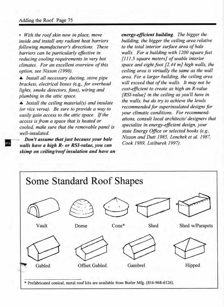
Some Standard Roof Shapes
Vault Dome Cone* Shed Shed w/Parapets
Gabled Offset Gabled Gambrel Hipped
* Prefabricated conical, metal roof kits are available from Butler Mfg. (816-968-6126).

Adding the Roof Page 76
Dutch Hip Framing OptionsThis option is often used onrectangular buildings as amore interesting substitutefor a gabled roof.
Depending on the framingsystem (three possibilitiesshown here), some roofweight can be distributed tothe shorter end walls. Thisroof shape also overhangsall four walls. For detailedinformation on roofframing, see Gross (1984).
space forscreened,louvered vent
common truss(doubled here)
Historically, square or nearly-square bale-walledbuildings were covered with a lightly-framed hiproof. The advantage is the nearly equal distributionof roof weight on all four walls.
A short ridge can bescabbed on to modifythe pyramidal profileand provide for adequateventing of the atticspace (a very importantconsideration).
Two-Story, Loadbearing OptionsUsing Super-Trusses™
Page 77 Adding the Roof
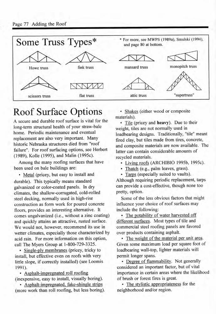
Some Truss Types*
Howe truss fmk truss
* For more, see MWPS (1989a), Smulski (1994),and page 80 at bottom.
mansard truss monopitch truss
scissors truss
I\J\N/I/I/1flat truss attic truss "supertruss"
Roof Surface OptionsA secure and durable roof surface is vital for thelong-term structural health of your straw-balehome. Periodic maintenance and eventualreplacement are also very important. Manyhistoric Nebraska structures died from "rooffailure". For roof surfacing options, see Herbert(1989), Kolle (1995), and Malin (1995c).
Among the many roofing surfaces that havebeen used on bale buildings are:
• Metal (pricey, but easy to install anddurable). This typically means standardgalvanized or color-coated panels. In dryclimates, the shallow-corrugated, cold-rolledsteel decking, normally used in high-riseconstruction as form work for poured concretefloors, provides an interesting alternative. Itcomes ungalvanized (i.e., without a zinc coating)and quickly attains an attractive, rusted surface.We would not, however, recommend its use inwetter climates, especially those characterized byacid rain. For more information on this option,call The Myers Group at 1-800-729-3325.
• Single-ply membranes (pricey, tricky toinstall, but effective even on roofs with verylittle slope, if correctly installed) (see Loomis1991).
• Asphalt-impregnated roll roofing(inexpensive, easy to install, visually boring).
• Asphalt-impregnated, fake-shingle strips(more work than roll roofing, but less boring).
• Shakes (either wood or compositematerials).
• Tile (pricey and heavy). Due to theirweight, tiles are not normally used inloadbearing designs. Traditionally, "tile" meantfired clay, but tiles made from tires, concrete,and composite materials are now available. Thelatter can contain considerable amounts ofrecycled materials.
• Living roofs (ARCHIBIO 1995b, 1995c).• Thatch (e.g., palm leaves, grass).• Tarps (especially suited to vaults).
Although requiring periodic replacement, tarpscan provide a cost-effective, though none toopretty, option.
Some of the less obvious factors that mightinfluence your choice of roof surfaces mayinclude the following:
• The potability of water harvested offdifferent surfaces. Most types of tile andcommercial steel roofing panels are favoredover products containing asphalt.
• The weight of the material per unit area.Given some maximum load per square foot ofloadbearing wall-top, lighter materials willpermit longer spans.
• Degree of flammability. Not generallyconsidered an important factor, but of vitalimportance in certain areas where the likelihoodof brush or forest fires is great.
• The stylistic appropriateness for theneighborhood and/or region.

Adding the Roof Page 78
A Simple Straw-Bale Roof IdeaA long-held desire of many straw-bale
aficionados has been to reduce the amountof wood used, while retaining adequateinsulation. Vaults and domes can work.Another idea, using ferro-cement and anelastomeric coating, is shown at right.
elastomericcoating
metal flashingwith drip ~edge
gutter
mesh-reinforcedferro-cement
fill gaps withcob mixture
planks ordecking
fascia and "stop" for bales
The Shed Roof OptionDue perhaps to its lack of visual pizazz, thesimple, low-pitch, shed roof is generallyshunned by both architects and owner-designer-builders. With a few porches,however, this ugly duckling takes on amodest charm. And for the owner-builder,at least in regions where snow loads areminimal, it offers some attractiveadvantages:
• If we exclude the flat roof (dumb,dumb, dumb) and the very low, gabled roof(why bother?, and few do), it covers a givenstructure with the minimum square footageof roof surface. Less materials, less labor,less cost.
• With a single gutter and down spout, allthe water harvested off the roof can bechanneled safely away from the base of thewalls onto vegetation, or into a cistern forstorage.
• As with a gabled roof constructed withtriangular trusses, the whole roof structure ismade up of a single, repeated element.Once you've got the first one attachedcorrectly, all the rest are "no-brainers".
• If 14 inches [35.6 cm], or more, high"truss joist Fs" (a.k.a. Til's, woodenI-beams) are used, long spans are possible,with adequate space available for
superinsulation. They can be ordered invarious heights and in custom lengths fargreater than you'll ever need.
Wooden I-Beam (TJI)
Allows deep insulationwith ventilation; saveslarge-diameter trees
• The necessity of having one end of theTJI's, or rafters, higher than the other,provides the opportunity to insert clerestorywindows directly under the roof, where theycan be easily shaded by a modest overhang.
Shed Roof Rafter Details
Use brace or wedgeat each rafter/TJI
Space the two outside rafters/TJI'son each side of end-wall bales;trim bales flush with roof
!
I- - i
END VIEW

Page 79 Adding the Roof
Options for Ceiling Materials• Sheet rock (a.k.a. drywall, gyp board). Thisold standard is cheap, relatively non-toxic,and fire-resistant. It is also heavy andcumbersome to install overhead withoutspecialized equipment. For tips on how-to,see Ferguson (1996). To get a continuous,smooth surface, ready for painting, one mustfill the joints and sand the filler materialsmooth. No one we've ever met seems toenjoy the last-mentioned step, and manyflat-out hate it. Some builders avoid this stepby filling the joints, staining the ceiling with acheap, dark stain and then stapling rolls ofreed or split-bamboo fencing to the ceiling.The long, black-coated staples used fortelephone wire installation work well, and arenearly invisible, but do require a special staplegun.
• Wood in various forms. Depending on yourdesign, your wood may be attached to thebottom of something (e.g., a none-too-pretty,pre-engineered truss) or on top of somethingthat you want to see (e.g., a handsome roundor squarish beam). People have used:
—Commercial tongue and groove planking—Stained or singed plywood, or the
equivalent. An unusual option here isWheatSheet, a hard, paneling material madeby binding wheat straw with a resin. Forinfo, contact Naturall (sic} Fiber Board, Box175, Minneapolis, KS 67467; 913-392-9922.
—Rough cut planks. Something like blackplastic sheeting, placed on the upper surfaceof the planks, will both provide an air/vaporbarrier and keep fragments of your insulationfrom dribbling down through the inevitablecracks into your caviar.
—Peeled saplings (a.k.a. lattias), cane,bamboo, etc. Rather than placing them atright angles to the beams , one can anglethem and reverse the direction between eachconsecutive beam to form an attractive"herringbone" pattern.
• PGB3. This unusual product, consistingalmost entirely of compressed straw, comes insheets that are four feet by eight feet by oneand a half inches. The surface has a lot oftexture and gives the board the properties ofan acoustical panel (for info contact BioFab at(916)243-4032 or e-mail them at<[email protected]>).
Straw-Bale Ceiling Insulation
metal strapping(consider usingwooden blockingalong each side oflog)
V
peeled log (a.k.a. vigd)
RBA
light, 2-tie bales preferable(consider using a fire retardanton bales)
air/vapor barrier(e.g., plastic sheeting)
rough-cut planking
straw flakes

Adding the Roof Page 80
Ceiling Insulation OptionsFor unbiased articles comparing commontypes of insulation, see Wilson (1995a; 1996).A wide variety of options have been used,including:
• Fiberglass, in several forms.• Cellulose, from recycled newspaper, inseveral forms.
• Cotton fibers, from recycled fabric trim-mings, in several forms.
• Foam board
• Structural, insulative panels (for a combinedceiling and roof). Typically these panels havefoam sandwiched between two sheets oforiented strand-board (a.k.a., OSB). Aninteresting alternative, made with strawbetween the sheets, is being manufacture byAgriboard. Call them at (515) 472-0363 ore-mail them at <[email protected]>.
• Loose straw, flakes or bales, including balesused both as the structural roof and theinsulation in domes and vaults (see Lerner1997). Especially when using loose straw, itis advisable to first treat the straw with a fireretardant. For specific information onretardants, see page 19. One approach totreating loose straw has been to first immerseit in the solution and then spread it out ontarps or a concrete slab for drying. If yourretardant is water soluble, you must re-treatthe straw if it is rained before you get it underroof.
• Surplus sleeping bags containing "fiberfill".Sometimes bought very cheaply (from theU.S. Forest Service), and stacked severalhigh, they are performing well in one smallstructure in New Mexico. Human ingenuityat its best, we'd say.
Raised-Heel Truss Ceiling
spaces within box-beam RBAand between trusses stuffedwith flakes of straw
insulation continuing outover the exterior walls atfull thickness
bales resting on wooden slats carried by bottom chordof trusses (Lighter insulation, like blown cellulose,can rest directly on the sheetrock.)
Step 6. Letting the Walls CompressC/flclllcngCI to patiently allow the bale walls to complete their compressionalresponse to the "dead load" exerted by the RBA/roof/ceiling/insulation system, and to usethis opportunity to work comfortably inside your building on a variety of tasks.
Walk-Through* Unless your design includes a tie-downsystem that enables mechanical compression(see page 73), you must now let the wallsgradually compress. Select two, or more,points along each wall at which toperiodically measure the distance from thetop of the toe-up (or floor surface) to the topof the RBA (or, later, the bottom of theceiling surface). Number the locations andrecord the measured distances such that youcan compare each set of measurements to theprevious set. For two different approachesto measurement, each reflecting for adifferent degree of anal retentivity, see page86.
The initial response to loading is rapid,but then begins to taper off. Experiencesuggests that complete compression mayrequire any\vhere from three to about sixweeks. Depending on initial bale compactionand roof weight, total compression will varyfrom some fraction of an inch (a cm or less)to several inches (about five or six cm).During the settling period, you shouldoccasionally adjust your tie-downs to removeany slack. When all of the measurements ina set show no change from the previous set,you can safely proceed with surfacing thewalls, as described in Step 7.
* With the tops of the bale walls nowprotected by the new roof and the bottomcourse sitting safely up off the ground on atoed-up, waterproofed foundation and draped
Page 81 Letting the Walls Compress
with a waterproof membrane, you can catchyour breath. Use this respite for things like:
—recreating and reconnecting with lovedones;
—tweaking any ornery bales into finalposition;
—adjusting the verticality of door andwindow frames, as needed, and connectingthem securely to the bale walls with dowels ormetal pins;
—installing the doors and windows;—and, creating the floor, if this has not
already been done. If the bales have beenstacked on a wooden deck carried by basementwalls, stem walls or piers/columns, the floor isalready in place. Similarly, a slab-on-gradecreates the floor and the foundation with asingle "pour" of concrete.
Although the floor may end up beingcreated at different points in differentbuildings, we have chosen to deal with thequestion of insulation under floors in just twoplaces - right here and on page 88, where weillustrate several options. During the designprocess, you should have made a decisionwhether or not to insulate and if so, with whatand to what degree. Among the things thatyou might consider are listed below:
1. The regional climate and the micro-climate at your site.
2. The type, or types, of floor you havechosen.
3. Whether the floor will be heated and/orcooled by pipes through which water or, less

Letting the Walls Compress Page 82
commonly, air will be circulated.4. Whether you are using a frost-protected,
shallow foundation, since floor insulation canincrease the amount of insulation required atthe perimeter (see HUD 1995).
5. The calculated or guesstimated paybacktime for the investment, and the planetarycosts of not doing it.
Our "model" building has a high-massfloor created within the above-grade collar.We are using no insulation around theperimeter of our foundation or under ourfloor, since our "model" climate requires verylittle heating or cooling.
The finished floor surface should be at least1.5" [3.9 cm] below the top of the collar toprotect the bales from any interior flooding.We have specified a high-mass floor so thatwinter sunlight (i.e., solar radiation), enteringthrough south-facing glazing, can hit, and beabsorbed by, the floor. This daytime storageof heat will prevent room air temperaturesfrom becoming uncomfortably high during theday. At night, this same heat will "bleed"back out, helping to keep the space frombecoming undesirably cool.
—Creating non-loadbearing interiorpartitions, leaving an adequate gap abovethem to allow for the settling that may stilltake place. An alternative approach is topostpone creation of the interior partitions,with any incorporated plumbing and wiring,until the interior surfacing is in place on theexterior bale walls. Then, with all thesurfacing materials in place (and all thecompressing finished), you no longer needs toguess how much of a gap to leave to allow forsettling.
This approach also minimizes the amountof patching required if one eventuallyrelocates a partition wall. See pages 85-87
for options regarding the creation andattachment of partition walls.
—Extending the plumbing into, or up intothe interior space. If you do choose to installsome, or all, of the partitions at this point,you can also complete any plumbing thatbelongs in them (see Massey 1994).
There are two obvious ways to get anywater lines (cold or hot) into your straw-balehouse. The first is to bring any pipes inunder your foundation/footings and leavethem "stubbed out" at the appropriatelocations when you create the floor. If aproblem ever develops with one of theseburied pipes, you will either destroy part ofyour floor (if you can pinpoint the leak) or,more likely, abandon all piping under thefloor The logical thing to do then, is toconsider using the second option, which youmight have been better off using to beginwith.
That involves bringing the pipe thatprovides cold water to the structure up out ofthe ground outside the wall, at one or morelocations opposite a single fixture (e.g., akitchen sink), or opposite an interior"plumbing wall", preferably framed with2"X6" [5X15 cm] lumber. Skillful, careful useof the tip of a small chain saw will create ahole, sloped slightly upward toward theinside, for a "sleeve " of plastic pipe. Insertthe sleeve and plug any space around it withyour cob mixture. The pipe(s) can then beplumbed through the bale wall and into theframe wall. To safely use this option, youmust be able to insulate the pipes to preventfreezing, even during record low temp-eratures. In colder climates this may not beeconomically possible.
If you cannot avoid running water pipesalong straw-bale walls, at least isolate them

Page 83 Letting the Walls Compress
carefully and completely from the straw.—Equipping the straw-bale walls withwooden elements to enable the hanging ofcabinets, bookcases, etc. If these elementswill be hidden by the plaster, map theirposition precisely on a diagram and save itfor later use. We 'II cover some of the variousoptions for hanging things on straw-balewalls in Step 8.
—Installing, in any partitions created atthis point and in the exterior walls, any phonejacks, antenna cable, electrical boxes andwiring (see Traister 1994, Cauldwell 1996).
—Rounding/trimming off bales at exteriorcorners and at door and window openings, asdesired, to provide for a "soft-profile"finished appearance. This is also the time totrim off any undesired protrusions on yourwall surfaces (a line trimmer/"weed whacker"works beautifully for this). Any niches,notches, alcoves, etc., should all be created atthis time using a small chain saw or, betteryet, a small electric grinder, equipped with acable-twist, flat wire wheel or a cutting wheelwith chainsaw teeth on the circumference(called the Lancelot/ Both are illustratedbelow. The wire wheels are cheaper and
never require sharpening, but (arguably) cuta little less quickly. They are available fromwelding supply stores. If none of your localhardware stores, or specialty tool suppliers,carry the Lancelot contact King Arthur Toolsat (800) 942-1300.
When using any of the above mentionedtools to cut straw, you should always wearsafety goggles and a dust mask (doessomeone have to die from "yellow-lungdisease" before this becomes automatic?).Chainsaws, grinders and even line trimmersare dangerous tools, capable of doing majordamage to the operator or those nearby. Usethem only with great care.
Niches and Counter-Niches
(idea from Bill & Kalla Buchholz) (idea from Jon Ruez)

Letting the Walls Compress Page 84
Bale Tweaking Tools
6" X 6" X 10[1.5 X 1.5X25.4 cm]
Big Sledge Wooden Maulhandle mounted in hole or on side
pipemetal plate'
Tamper/"Persuader"
Wiring OptionsPound in 2" X 4"[5X 10cm] stake,_then attach boxwith dry wallscrews
1"X4" [2.5 X 10 cm] boardin seam between bales; boxside-mounted; stucco nettingcan be attached to both ends.
• Wires in metal or flexible plastic conduit on wallsurface; or in groove (dug with claw hammer, or cutwith tip of chainsaw or circular saw); or run underfloor and "popped up" to boxes.• Wires in surfaced-mounted "decorator" conduit(attached after the wall has been surfaced).• Plastic-sheathed cable (e.g., Romex 12/2) pushedinto 2 1/4" [5.7 cm]-deep groove cut into walls.Hold in place with "Roberta pins" (see page 92).• Cable run horizontally on a bale course duringwall raising. Position wires about 3" [7.6 cm] fromthe inner edge of the bales to prevent risk of hittingthem when pinning).
If doing your own electrical, see Traister (1994)and Cauldwell (1996); Re: EMFs from -wiring, seePinsky (1995).
High-Mass Floor Options1" X 1" [2.5 X2.5 cm] [0.6 m]
Bricks or blocks (e.g., fired adobes) on sand(see Ring 1990), stone on earth (Laporte 1993)Tiles on slabEarth (see Laporte 1993, Steen et al. 1994,Steen and Steen 1997b, and several articles inIssue 17 of The Last Straw)Compacted soil-cement / rammed earth (seeBerglund 1985, McHenry 1989, Easton 1996)Concrete—regular slab-on-grade—regular slab poured over bale insulation (see
illustration on page 88)—scored or embossed slab (pressed-in pattern)—large, thick, poured-in-place "tiles" (frame
stays in place)
—moveable patternedframe
1" X4" [2.5 X 10cm]
Coloring Concrete• Mix dye with the concrete before pouring.• Sprinkle on and "float" in during final finishing.• Staining: commercial or homemade (artist
pigments, or use ferrous sulphate which is cheapand available from agricultural, chemical, orfertilizer suppliers to get a yellowish, reddishbrown).
• Apply special concrete paints.

Page 85 Letting the Walls Compress
Options for Interior Partitions• Standard frame (2"X 4" [5X10 cm] or2"X6" [5X15.2 cm]), covered with sheetrockor some other type of paneling. You maywant to use WheatSheet, a thin panel madeentirely from straw and a formaldehyde-free,polymer-based binder. For accessinformation, see "Options for CeilingMaterials" on page 79.• Infilled standard or widely spaced frameto which stucco netting has been attached onboth sides, creating cavities that are stuffedwith straw. Paster is then applied to theresulting surface with hand or trowel,producing an undulating surface reminiscentof the finished bale walls.
Another infill option would involvetamping "light clay/straw" mix into the spacebetween formboards temporarily attached tothe frame (see Laporte 1993).• Shipping pallets that have been stuffedwith flakes of straw (for sound insulation)before being stacked and connected to form apartition wall. A thick coat of earth plaster,well keyed into the spaces between theboards, will probably stay on just fine withoutstucco netting. Pallets which would otherwisetake up scarce space in a landfill, can usuallybe acquired without money changing hands.The planet will love you for converting awaste material into a free resource.• Wattle and daub. The "wattle" is a wovenframework of saplings, bamboo, reeds, etc.,intertwined with smaller twigs or branches.The daub is usually earth plaster, smearedonto both sides of the panel.• Hanging dividers. If the only function of aspecific divider is to provide visual privacy,why spend a lot of time and money building aheavy, "permanent" partition that you'llprobably end up wanting to move eventually.
Consider hanging a fabric partition from thoselittle gizmos that slide along a metal trackattached to the ceiling. This system savesspace, while providing visual privacy whenneeded.• Furniture walls. As above, floor standingelements like bookcases and storage units canbe used to provide visual privacy withoutcreating a permanent monument toover-building.• Earth materials.
—Adobe (McHenry 1989, Houlen andGuillard 1994) and Cob (Bee 1997, Smith1997) can be used to create handsome,relatively narrow (8" [20.3 cm] is a suggestedminimum), sound- dampening walls that alsocontribute to the thermal mass within the baleenvelope. No matter where situated, they willcontribute to the effectiveness of passive andactive cooling strategies, but are of lessbenefit in passive solar heating strategiesunless they receive direct sunlight for asignificant part of the winter day. For specificsuggestions on combining earth materials withstraw bales in your design, see Issue 17 ofThe Last Straw.
—Rammed earth (Easton 1996) is seldomconsidered for a partition wall unless the wallwill also be carrying roof weight, as in thehybrid design with the inverted trusses onpage 22, bottom left.• Straw bales. Whole bales, either flat or onedge, have seldom been used for interiorpartitions, since the resulting walls (ditto forrammed earth) take up lots of precious space.Three-tie bales converted into four-tie balesthat are then cut in half, would reduce thestraw thickness to about 11" [28 cm]. A wallmade from these "straw slabs", perhapssandwiched between 2"X6" [5X15.2 cm]

Letting the Walls Compress Page 86
Marts' Method
- • V v
.
v vX \
vX X\
N
\t angle,
metal bracket
Separate"2"X2"[5X5 cm]
Segment of\c ruler
graduated inmillimeters
Calibrationmark
\Separatepiece oflumber(see above)
studs spaced about 4' apart, would stillprovide a good sound barrier andpleasantly thick walls.
We do know of one building (seebelow), where a standard bale wall,with doorways in it, was used as aloadbearing substitute for a ridge-beam.
• Compressed strawboard. Theboard typically used for partitions is2-1/4" [5.7 cm] thick and consists ofcompressed straw panels with paperglued onto both faces. This type ofboard has been widely used in England,and elsewhere, to replace sheetrock-covered frame walls. For informationon PGB (Pacific Gold Board), contactBioFab, in northern California, at (916)243-4032 or <[email protected]>.If enough demand develops, a similarproduct will be manufactured in Texasby Agriboard. Contact them at (515)472-0363 or <[email protected]>.• Beverage cans and/or bottles laidup in earth- or cement-based mortar(see Reynolds 1990).
Steve's Method
Generic tapemeasure
Measuring Compression Progress
,\>
\
v\\
X N
x \
\

Page 87 Letting the Walls Compress
Attaching Partition Walls to Bale WallsUnder certain circumstances (e.g., in areaswith minimal seismic risk) and with certainwall types (e.g., frame walls), attachment atthe top and bottom of the wall may be judgedsufficient. Typically, however, partition wallsare attached to exterior bale walls. Thetechnique chosen in a particular case willdepend largely on the material(s) used inbuilding the partition wall.
Some options, arranged by partition type,are shown below. Many can also be used(although some adaptation may be needed) toconnect the walls of a straw-bale addition to apreexisting structure.
Frame Side View
For info on "Gringo Grip",call Slra\v Bale BuildingSystems at 1-800-734-8091.
lag boltthrough studinto 2"X4"stake
Adobe Or Cob Side View
threaded rod with bend on oneend, plywood washer on other
bent expanded metal lath attachedto wooden stakes in bale wall andextended into earth wall
as above, except strip of lathincorporated and pegged intostraw-bale wall during stacking
Cob only
2"X2" or 4"[5X5 or 10cm] stake
bamboo pin
sapling pin (e.g., willow)
Side View
Straw Bale Top View
longer, diamond-shaped,plywood washer with thetwo sharper pointsaligned vertically
threaded rod
sharp pin (e.g., bamboo, rebar)
sharp pins "toe-nailed" throughpartition-wall bales into exterior-wallbales
Not illustrated, is the technique of buildingthe straw-bale partition wall and exterior balewall simultaneously, knitting the two togetherby having some of the bales in the partitionwall extend into the exterior wall. Model itwith dominoes, or the equivalent, beforedoing it!

rLetting the Walls Compress Page 88
Insulating FloorsUnder Slabs• foamboard (of a type that can withstandthe loading without compressing)
• pumice (provides an R-value of about 2.2per inch [RSI-value of 15.2 per meter])
Bales"
repeatedbracing^
foam board concrete slab
rT-TT^T 'f~1 ' 'I' T- VrTV
gravel/sand vapor barrieras needed
See The Last Straw, Issue 6, page 14, for photos of a slabbeing poured over bales, an^ARCHIBIO (1995d) for how-to.
Between Floor Joists/Supports• fiberglass• cotton• cellulose, especially dense-packed• integral insulation and structural floor(described, with access information for apanel with a strawboard core, on page 80).
Bales or flakes between raised joistsair/vaporbarrier "*
TJI joist
board supports
Well-VentilatedCrawl Space
f~ flooring
subflooring
screen basket
air/vaporbarrier
sand
soil
Bales on gravel between supports
levelingguide
spiked 2"X4" [5X10cm] set and leveled in concrete """P6* between bale
concrete "~>s. \>
'l///, ' £Jl: t
S//, &
^
~T\
^^, ^
r •-,~~J< If
&subfloor
\vaporbarrier
Graver* See The Last Straw. Issue 12, p. 22, on this example from Mongolia.
A wet ground surface under a raised floor ••-may contribute to "rising damp" (water vaporin outside air) that could condense within,and lower the R/RSI-value of, the suspendedinsulation. Strategies to prevent this includeproviding as much ventilation as possible forthe "crawl space" and covering the groundunder the building with a layer of plasticsheeting, held down and protected by a layerof sand. Good perimeter drainage is alsoneeded to insure that the sand stays dry.
In cold climates, warm, moist inside airmust not be allowed to move downwardthrough the floor materials. (See the diagramto the left, and CMHC 1994.) The danger liesin the possibility that the water vapor willcondense, creating liquid water that willdamage the floor joists and reduce the R/RSI-value of the insulation.