robust capon beamforming in presence of large doa mismatch
TRANSCRIPT

Robust Capon beamforming in presenceof large DOA mismatch
W. Zhang, S. Wu and J. Wang
In the presence of significant direction-of-arrival (DOA) mismatch, arobust Capon beamforming approach is proposed. The basic idea ofthe proposed method is first to estimate a set of the desired steeringvectors corresponding to DOAs coming from a DOA uncertaintyregion by using the uncertainty set based approach, then a Bayesianapproach is employed to obtain the weight vector.
Introduction: The Capon beamformer chooses the weight vector byminimising the array output power subject to a look direction constraint[1, 2]. The standard Capon beamformer (SCB) is very sensitive to steer-ing vector mismatches caused by various factors, such as DOAmismatch and array calibration error [3, 4]. To improve the robustnessof the SCB, the Bayesian beamformer [5] was proposed for the specificcase of DOA mismatch. However, it is not robust against other types ofmismatches. Based on the uncertainty set of the steering vector, therobust Capon beamformer (RCB) was proposed in [4]. However, inthe presence of large DOA mismatch, the RCB requires a large sizeof uncertainty set to achieve robustness against the increased mismatch,which degrades its output signal-to-interference-plus-noise ratio (SINR).To mitigate this problem, an advanced robust beamformer was proposedin [6]. An important advantage of the beamformer of [6] is that it canflexibly control the beamwidth of the robust response region withconstraints on array magnitude response. Motivated by [4] and [5], weherein propose a novel robust Capon beamformer to achieve robustnessagainst large DOA mismatch.
Background: Consider a uniform linear array (ULA) of M sensors, thereceived data of the ULA at the nth snapshot can be expressed as
x[n] = [x1[n], x2[n], · · · , xM [n]]T =∑Pi=1
a(ui)si[n] + n[n] (1)
where xi[n] is the received data at the ith sensor, si[n] is the ith source,[·]T denotes the transpose operation, n[n] is the noise with a power s2, Pis the number of signals, and
a(ui) = [1, e−j2pd sin (ui)/l, · · · , e−j2p(M−1)d sin (ui)/l]T (2)is theM × 1 steering vector of the ith signal in direction ui, with d beingthe adjacent sensor spacing and l denoting the signal wavelength.
Without loss of generality, we assume that the first signal is the signalof interest (SOI). Then the Capon beamformer is obtained by solving thefollowing optimisation problem:
minw
wH Rxx w subject to wHa(�u1) = 1 (3)
where w is the M × 1 complex weight vector, �u1 is the presumed DOAof the SOI, and Rxx is the sample covariance matrix, given by
Rxx = 1
N
∑Nn=1
x[n]xH [n] (4)
where N is the number of snapshots. The solution to (3) is given by
w = m R−1xx a(�u1) (5)
where m is a scalar.
Proposed method: By utilising the RCB approach, the proposedmethod first estimates a set of desired steering vectors correspondingto DOAs within a DOA uncertainty region where the SOI arrives witha high probability; the weight vector can then be obtained using aBayesian approach.
The RCB approach is formulated as [4]
mina
aH R−1xx a subject to ‖a− a(�u1)‖2= 1 (6)
where ‖ · ‖ denotes the Euclidean norm, a is the estimate of the desiredsteering vector, and 1 is the uncertainty level. The solution to (6) is
ELECTRONICS LETTERS 3rd January 2013 Vol. 4
given by
a = a(�u1) − (I+ l Rxx)−1a(�u1) (7)where l is the Lagrange multiplier, which can be obtained as the solu-tion to the spherical constraint equation
g(l) =‖(I+ l Rxx)−1a(�u1)‖2= 1 (8)Since the actual DOA of the SOI is unknown, we assume that the SOI
come from a DOA uncertainty region defined as F = [�u1 −D, �u1 +D],where D is the DOA uncertainty range [6]. In practice, a discrete setof J points F = [F1,F2, · · · ,FJ ] is used. Now we utilise the RCBapproach to estimate a set of desired steering vectors corresponding to{a(Fj)}Jj=1:
aj = a(Fj) − (I+ lj Rxx)−1a(Fj) j = 1, · · · , J (9)where aj and lj are the desired steering vector and the Lagrange multi-plier, respectively. Similarly, the Lagrange multiplier lj can be obtainedby solving the following problem:
g(lj) =‖ (I+ lj Rxx)−1a(Fj) ‖2= 1j (10)where 1j is the uncertainty level for a(Fj).
The Bayesian beamformer is given by [5]
wB = m Rxx
∑Jj=1
p(Fj|X)a(Fj)( )
(11)
where X denotes a collection of N array observationsx[n], n = 1, · · · ,N ; p(Fj|X) is the a posteriori probability densityfunction (PDF) at Fj given the observations X. The a posteriori PDFis approximately given by
p(Fj|X) = cp(Fj) exp {Ng(a(Fj)H R−1xx a(Fj))−1} (12)
where c is a normalisation factor ensuring that the PDF sums to one, andg is a constant.
Motivated by the Bayesian beamformer, the proposed beamformerusing the estimated desired steering vectors in (9) can then be given by
wP = m Rxx
∑Jj=1
�p(Fj|X)aj( )
(13)
where �p(Fj|X) = cp(Fj)exp{Ng(aHj R−1xx aj)−1}.
Simulations: In this Section, simulations are carried out to investigatethe performance of the proposed method compared with the SCB,RCB, the Bayesian beamformer of [5] and the beamformer of [6]. Weconsider a ULA with M = 10 sensors and half-wavelength spacingbetween adjacent sensors. The SOI arrives from u1 = 08. Two inter-ferers with interference-to-noise ratio (INR) of 30 dB impinge on thearray from the directions −408 and 508, respectively. The array issteered towards the direction �u1 = u1 + Du, where Du is the DOAmismatch. Here, both gain and phase errors are considered. In thiscase, the actual steering vector can be written as a(u) = Ga(u),where G = diag[a1e−jc1 , · · · ,aMe−jcM ] is the diagonal matrix of thecalibration errors, with ak and ck standing for the amplitudeand phase errors, respectively. We assume that the amplitude andphase errors have a uniform distribution: ak [ [0.8, 1.2] andck [ [−p/100,p/100]. Note that G changes from run to run whileremaining constant for all snapshots. The DOA uncertainty region forthe beamformer of [6] and the proposed method is given by [−68, 68],and the number of grid points of the DOA uncertainty region isfixed to J = 50. The uncertainty level for the RCB is 1 = 6, but{1j}Jj=1 = 1 are used in the proposed method. The a priori PDF isuniform with c = 1
50. The parameter g is set to 0.3, as [5] denotes. Allresults are averaged based on 100 independent simulation runs.
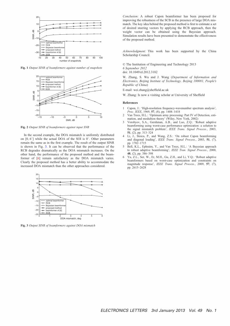
In the first example, the DOA mismatch is Du = 58. Fig. 1 showsthe output SINR of the beamformers against the number of snapshotswhen the signal-to-noise ratio (SNR) is 5 dB. Fig. 2 shows the outputSINR of the beamformers against input SNR for N = 100. As shown,the proposed method achieves the best performance among the beam-formers considered. Moreover, due to the impact of the gain andphase errors, the Bayesian beamformer cannot achieve sufficientrobustness.
9 No. 1
10 20 30 40 50 60 70 80 90 100
−30
−20
−10
0
10
20
SIN
R, d
B
number of snapshots
optimal beamformerRCBBayesian beamformerproposed methodbeamformer of [6]SCB
Fig. 1 Output SINR of beamformers against number of snapshots
−15 −10 −5 0 5 10−20
−15
−10
−5
0
5
10
15
20
SIN
R, d
B
SNR, dB
optimal beamformerRCBBayesian beamformerproposed methodbeamformer of [6]SCB
Fig. 2 Output SINR of beamformers against input SNR
In the second example, the DOA mismatch is uniformly distributedon [0, 68] while the actual DOA of the SOI is 08. Other parametersremain the same as in the first example. The result of the output SINRis shown in Fig. 3. It can be observed that the performance of theRCB degrades dramatically as the DOA mismatch increases. On theother hand, the performance of the proposed method and the beam-former of [6] remain satisfactory as the DOA mismatch varies.Clearly the proposed method has a better ability to accommodate theincreased DOA mismatch than the other approaches considered.
0 1 2 3 4 5 6−25
−20
−15
−10
−5
0
5
10
15
20
SIN
R, d
B
DOA mismatch, deg
optimal beamformerRCBBayesian beamformerproposed methodbeamformer of [6]SCB
Fig. 3 Output SINR of beamformers against DOA mismatch
ELECTRON
Conclusion: A robust Capon beamformer has been proposed forimproving the robustness of the SCB in the presence of large DOA mis-match. The key idea behind the proposed method is first to estimate a setof desired steering vectors by applying the RCB approach, then theweight vector can be obtained using the Bayesian approach.Simulation results have been presented to demonstrate the effectivenessof the proposed method.
Acknowledgment: This work has been supported by the ChinaScholarship Council.
© The Institution of Engineering and Technology 20136 September 2012doi: 10.1049/el.2012.3182
W. Zhang, S. Wu and J. Wang (Department of Information andElectronics, Beijing Institute of Technology, Beijing 100081, People'sRepublic of China)
E-mail: [email protected]
W. Zhang: Is now a visiting scholar at University of Sheffield
References
1 Capon, J.: ‘High-resolution frequency-wavenumber spectrum analysis’,Proc. IEEE, 1969, 57, (8), pp. 1408–1418
2 Van Trees, H.L.: ‘Optimum array processing: Part IV of Detection, esti-mation, and modultion theory’ (Wiley, New York, 2002)
3 Vorobyov, S.A., Gershman, A.B., and Luo, Z.Q.: ‘Robust adaptivebeamforming using worst-case performance optimization: a solution tothe signal mismatch problem’, IEEE Trans. Signal Process., 2003,51, (2), pp. 313–324
4 Li, J., Stoica, P., and Wang, Z.S.: ‘On robust Capon beamformingand diagonal loading’, IEEE Trans. Signal Process., 2003, 51, (7),pp. 1702–1715
5 Bell, K.L., Ephraim, Y., and Van Trees, H.L.: ‘A Bayesian approachto robust adaptive beamforming’, IEEE Tran. Signal Process., 2000,48, (2), pp. 386–398
6 Yu, Z.L., Ser, W., Er, M.H., Gu, Z.H., and Li, Y.Q.: ‘Robust adaptivebeamformers based on worst-case optimization and constraints onmagnitude response’, IEEE Trans. Signal Process., 2009, 57, (7),pp. 2615–2628
ICS LETTERS 3rd January 2013 Vol. 49 No. 1