road & bridge design publications - michigan · 2019-11-27 · road & bridge design...
TRANSCRIPT

Road & Bridge Design Publications
Monthly Update – November 2019
1
Revisions for the month of November are listed and displayed below and will be included in projects submitted for the March letting. E-mail road related questions on these changes to [email protected]. E-mail bridge related questions to [email protected].
Special Details
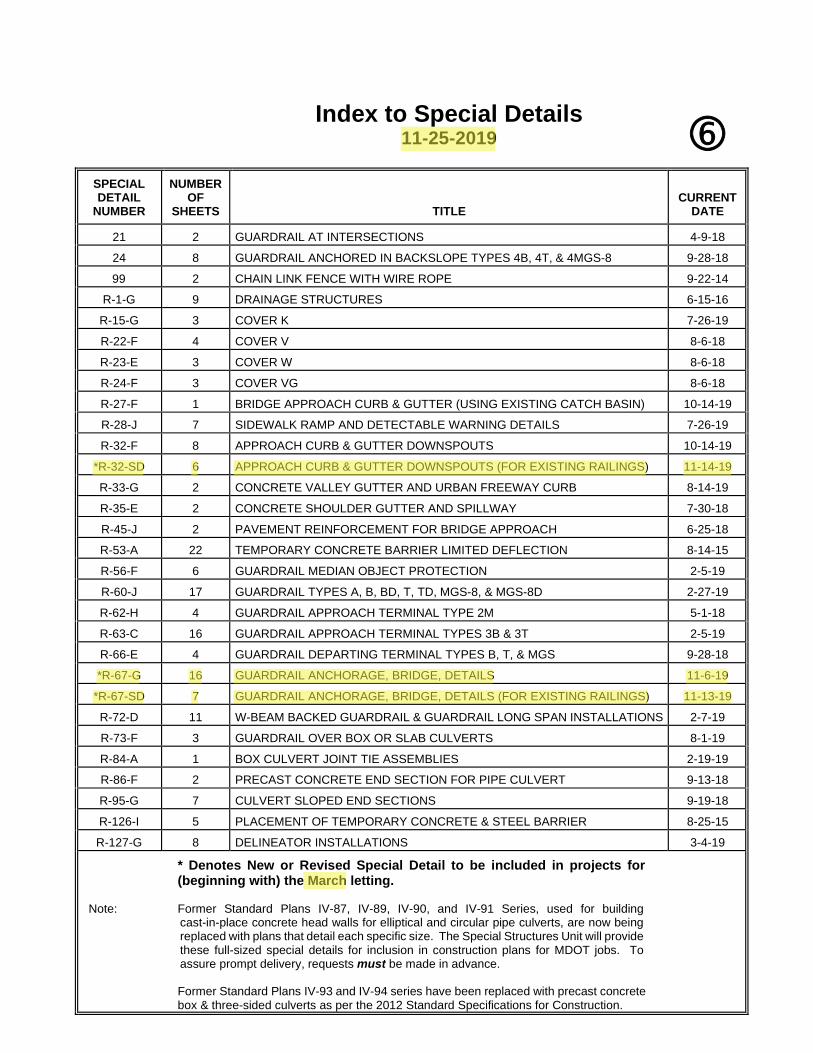
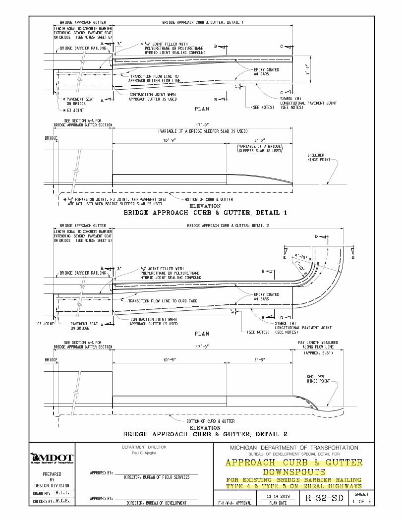
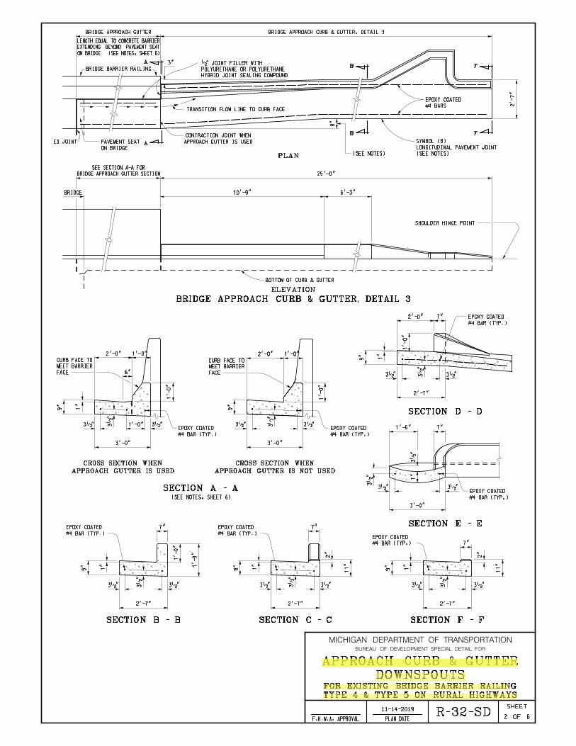
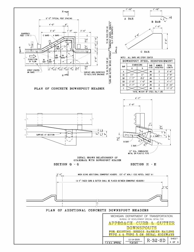
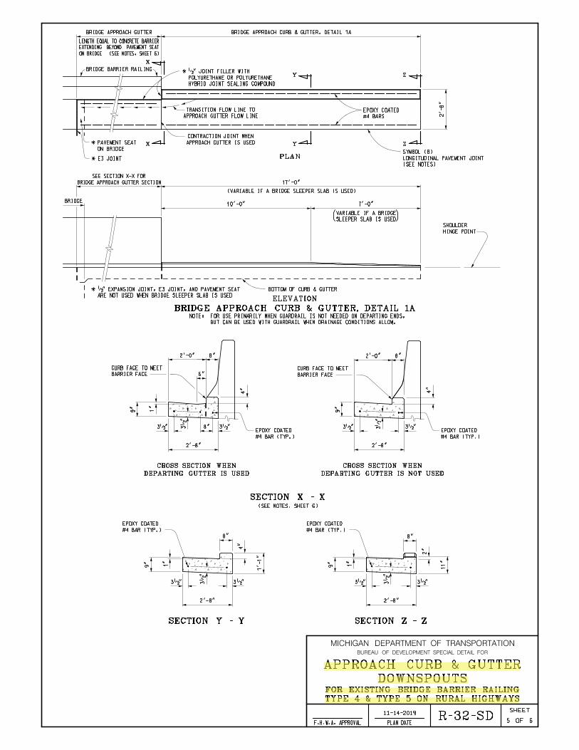
R-32-SD: Approach Curb & Gutter Downspouts (For Existing Bridge Railing): This is a new detail to be used only on projects when replacing the existing curb & gutter but retaining the existing bridge railing.
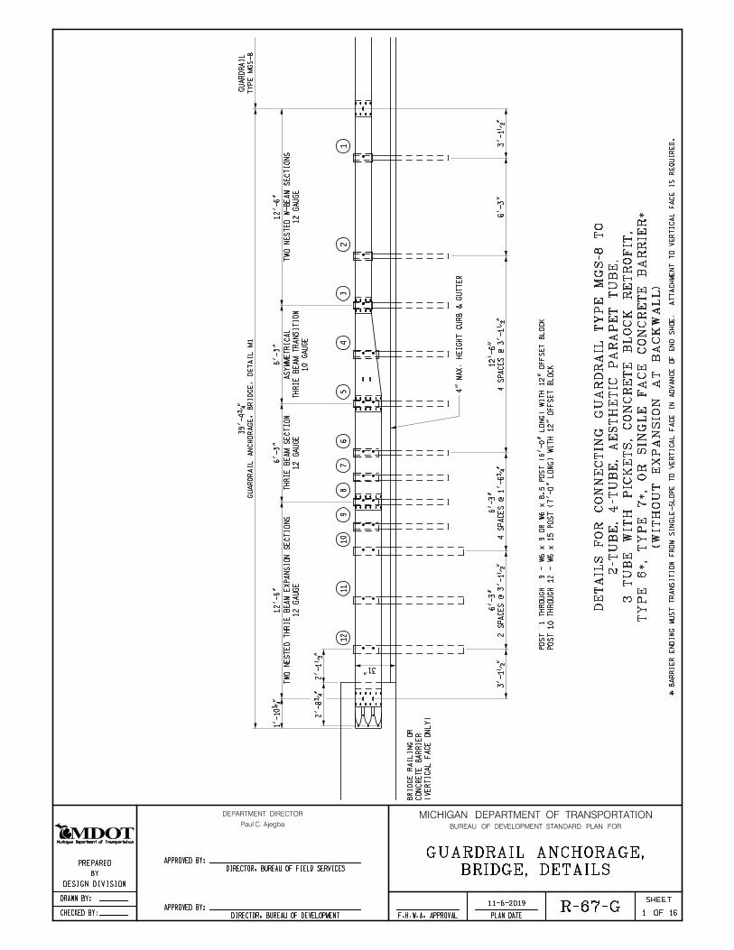
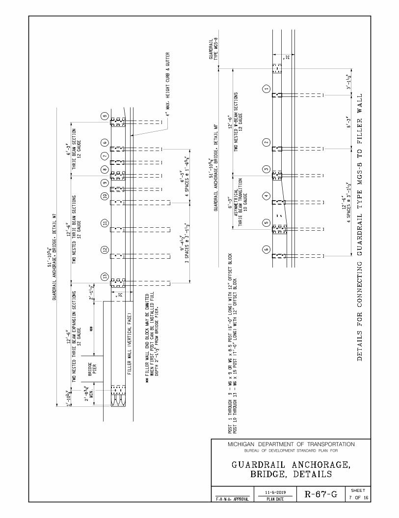
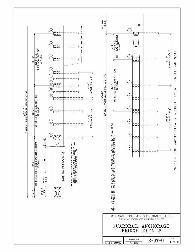
R-67-G: Guardrail Anchorage Bridge, Details: Removed the “T” anchorages and associated information. (This information has been transferred to new Special Detail R-67-SD for use on projects where a new guardrail anchorage will be attached to an existing bridge railing.)
R-67-SD: Guardrail Anchorage Bridge, Details (For Existing Bridge Railing): This is a new detail to be used only on projects when replacing a guardrail anchorage but retaining the existing bridge railing.
Road Design Manual
5.05.02: Consent to Construct Sidewalk: Updated the section to reflect the elimination of “mutual benefit” ROW consents.
6.01.06B: Pavement Selection Policy: Revised the threshold (from $1 million to $1.5 million) for the use of life cycle cost analysis in determining pavement selection.
6.06.08: Bridge Approach Curb & Gutter: Specified the parameter (for drainage area) to distinguish between moderate and greater drainage areas when using Bridge Approach Curb and Gutter, Details 6 & 7.
12.10.08: PITWS General Information: Revised the maximum longitudinal grade for newly placed and existing slabs from .2% to 2%.

Road & Bridge Design Publications
Monthly Update – November 2019
2
Bridge Design Manual
The following sections of the Bridge Design Manual have been updated with criteria to comply with AASHTO Manual for Assessing Safety Hardware (MASH):
7.02.27 (LFD & LRFD), 7.02.28 (LFD & LRFD), 7.02.28 A. (LFD & LRFD), 7.03.12 F.3. (LFD & LRFD), 7.07.02 (LFD & LRFD), 8.07.01 U. (LFD & LRFD), 8.09.02 B. (LFD & LRFD), 8.09.03 A. (LFD & LRFD), 8.09.03 I. (LFD & LRFD), 12.05, 12.05.01 & 12.05.02
These are a compliment to the Special Detail bridge railings (B-28-A, B-29-A & B-50-A) issued in September and October of 2019. Complimentary Bridge Design Guides for the railings will be issued in the near future.
The writeup for the 3 Tube with Pickets railing (previously issued Standard Plan B-27-A) was added to the following sections:
7.02.28 (LFD & LRFD), 7.02.28 A. (LFD & LRFD), 8.07.01 U. (LFD & LRFD) & 12.05.01
8.03 Y. (LFD & LRFD), 8.09.03 E. (LFD & LRFD): Updated notes to read the same and have clarity.
Updates to MDOT Cell Library, Bridge Auto Draw Program, etc., may be required in tandem with some of this month's updates. Until such updates to automated tools can be made, it is the designer's/detailer's responsibility to manually incorporate any necessary revisions to notes and plan details to reflect these revisions.
Index to Special Details 11-25-2019
SPECIAL DETAIL
NUMBER
NUMBER OF
SHEETS TITLE CURRENT
DATE
21 2 GUARDRAIL AT INTERSECTIONS 4-9-18
24 8 GUARDRAIL ANCHORED IN BACKSLOPE TYPES 4B, 4T, & 4MGS-8 9-28-18
99 2 CHAIN LINK FENCE WITH WIRE ROPE 9-22-14
R-1-G 9 DRAINAGE STRUCTURES 6-15-16
R-15-G 3 COVER K 7-26-19
R-22-F 4 COVER V 8-6-18
R-23-E 3 COVER W 8-6-18
R-24-F 3 COVER VG 8-6-18
R-27-F 1 BRIDGE APPROACH CURB & GUTTER (USING EXISTING CATCH BASIN) 10-14-19
R-28-J 7 SIDEWALK RAMP AND DETECTABLE WARNING DETAILS 7-26-19
R-32-F 8 APPROACH CURB & GUTTER DOWNSPOUTS 10-14-19
*R-32-SD 6 APPROACH CURB & GUTTER DOWNSPOUTS (FOR EXISTING RAILINGS) 11-14-19
R-33-G 2 CONCRETE VALLEY GUTTER AND URBAN FREEWAY CURB 8-14-19
R-35-E 2 CONCRETE SHOULDER GUTTER AND SPILLWAY 7-30-18
R-45-J 2 PAVEMENT REINFORCEMENT FOR BRIDGE APPROACH 6-25-18
R-53-A 22 TEMPORARY CONCRETE BARRIER LIMITED DEFLECTION 8-14-15
R-56-F 6 GUARDRAIL MEDIAN OBJECT PROTECTION 2-5-19
R-60-J 17 GUARDRAIL TYPES A, B, BD, T, TD, MGS-8, & MGS-8D 2-27-19
R-62-H 4 GUARDRAIL APPROACH TERMINAL TYPE 2M 5-1-18
R-63-C 16 GUARDRAIL APPROACH TERMINAL TYPES 3B & 3T 2-5-19
R-66-E 4 GUARDRAIL DEPARTING TERMINAL TYPES B, T, & MGS 9-28-18
*R-67-G 16 GUARDRAIL ANCHORAGE, BRIDGE, DETAILS 11-6-19
*R-67-SD 7 GUARDRAIL ANCHORAGE, BRIDGE, DETAILS (FOR EXISTING RAILINGS) 11-13-19
R-72-D 11 W-BEAM BACKED GUARDRAIL & GUARDRAIL LONG SPAN INSTALLATIONS 2-7-19
R-73-F 3 GUARDRAIL OVER BOX OR SLAB CULVERTS 8-1-19
R-84-A 1 BOX CULVERT JOINT TIE ASSEMBLIES 2-19-19
R-86-F 2 PRECAST CONCRETE END SECTION FOR PIPE CULVERT 9-13-18
R-95-G 7 CULVERT SLOPED END SECTIONS 9-19-18
R-126-I 5 PLACEMENT OF TEMPORARY CONCRETE & STEEL BARRIER 8-25-15
R-127-G 8 DELINEATOR INSTALLATIONS 3-4-19
* Denotes New or Revised Special Detail to be included in projects for (beginning with) the March letting.
Note: Former Standard Plans IV-87, IV-89, IV-90, and IV-91 Series, used for building cast-in-place concrete head walls for elliptical and circular pipe culverts, are now being replaced with plans that detail each specific size. The Special Structures Unit will provide these full-sized special details for inclusion in construction plans for MDOT jobs. To assure prompt delivery, requests must be made in advance.
Former Standard Plans IV-93 and IV-94 series have been replaced with precast concrete box & three-sided culverts as per the 2012 Standard Specifications for Construction.

Index to Bridge Detail Sheets 11-25-2019
DETAIL NUMBER
NUMBEROF
SHEETS TITLE CURRENT
DATE
B-22-E 5 BRIDGE RAILING, THRIE BEAM RETROFIT (R4 TYPE RAILING) 10-23-19
B-23-F 6 BRIDGE RAILING, THRIE BEAM RETROFIT (OPEN PARAPET RAILING) 10-23-19
B-26-F 8 BRIDGE RAILING, 4 TUBE 5-22-18
B-28-A 7 BRIDGE BARRIER RAILING, TYPE 7 9-27-19
B-29-A 8 BRIDGE BARRIER RAILING, TYPE 6 9-27-19
B-50-A 3 BRIDGE RAILING, CONCRETE BLOCK RETROFIT 10-15-19
B-101-G 2 DRAIN CASTING ASSEMBLEY DETAILS 7-26-18
EJ3AC 1 to 3 EXPANSION JOINT DETAILS 10-8-19
EJ4P 1 to 3 EXPANSION JOINT DETAILS 10-8-19
PC-1M 1 PRESTRESSED CONCRETE I-BEAM DETAILS 8-23-17
PC-2H 1 70" PRESTRESSED CONCRETE I-BEAM DETAILS 8-23-17
PC-4F 1 PRESTRESSED CONCRETE 1800 BEAM DETAILS 8-23-17
* Denotes New or Revised Special Detail to be included in projects for (beginning with) the March letting.
Note: Details EJ3AC & EJ4P are interactive, i.e. designers and detailers choose details based upon railing type and angle of crossing. Place all details appropriate for the project, structure specific information, and the Expansion Joint Device quantity on the sheet. The sheet shall then be added to the plans as a normal plan sheet.
Detail PC-1M, PC-2H and PC-4F shall have structure specific information and quantities added to the sheet. The sheet shall then be added to the plans as a normal plan sheet.
DEPARTMENT DIRECTOR MICHIGAN DEPARTMENT OF TRANSPORTATION
OF
SHEET
PLAN DATEF.H.W.A. APPROVALCHECKED BY:
DRAWN BY:
Michigan Department of Transportation
BUREAU OF DEVELOPMENT SPECIAL DETAIL FOR
APPROVED BY:
APPROVED BY:
Paul C. Ajegba
BY
PREPARED
DESIGN DIVISION
DIRECTOR, BUREAU OF FIELD SERVICES
DIRECTOR, BUREAU OF DEVELOPMENT 1
11-14-2019
6
DOWNSPOUTS
APPROACH CURB & GUTTER
B.L.T.
W.K.P.
BRIDGE APPROACH CURB & GUTTER, DETAIL 2BRIDGE APPROACH GUTTER
ON BRIDGE (SEE NOTES, SHEET 6)
EXTENDING BEYOND PAVEMENT SEAT
LENGTH EQUAL TO CONCRETE BARRIER
BRIDGE
ALONG FLOW LINE
PAY LENGTH MEASURED
BRIDGE APPROACH GUTTER SECTION
SEE SECTION A-A FOR
BOTTOM OF CURB & GUTTER
BRIDGE
BRIDGE APPROACH GUTTER SECTION
SEE SECTION A-A FOR
BRIDGE APPROACH GUTTER
ON BRIDGE (SEE NOTES, SHEET 6)
EXTENDING BEYOND PAVEMENT SEAT
LENGTH EQUAL TO CONCRETE BARRIER
C
C
B
BA
A
BRIDGE APPROACH CURB & GUTTER, DETAIL 1
BOTTOM OF CURB & GUTTER
APPROACH GUTTER IS USED
CONTRACTION JOINT WHEN
APPROACH GUTTER FLOW LINE
TRANSITION FLOW LINE TO
BRIDGE BARRIER RAILING
A
A
APPROACH GUTTER IS USED
CONTRACTION JOINT WHEN
ON BRIDGE
PAVEMENT SEATE3 JOINT
BRIDGE BARRIER RAILING
TRANSITION FLOW LINE TO CURB FACE
B
B
D
EE
D
PLAN
ELEVATION
PLAN
ELEVATION
BRIDGE APPROACH CURB & GUTTER, DETAIL 1
BRIDGE APPROACH CURB & GUTTER, DETAIL 2
HINGE POINT
SHOULDER
HINGE POINT
SHOULDER
(SEE NOTES)
LONGITUDINAL PAVEMENT JOINT
SYMBOL (B)
(SEE NOTES)
LONGITUDINAL PAVEMENT JOINT
SYMBOL (B)
8"
2'-
7"
17'-0"
10'-9" 6'-3"
8"
17'-0"
6'-3"10'-9"
4'-10" R
1'-10" R
(APPROX. 6.5')
#4 BARS
EPOXY COATED
#4 BARS
EPOXY COATED
SLEEPER SLAB IS USED
VARIABLE IF A BRIDGE
(
(VARIABLE IF A BRIDGE SLEEPER SLAB IS USED)
(SEE NOTES)
(SEE NOTES)
3"
3"
ON BRIDGE
* PAVEMENT SEAT
* E3 JOINT
ARE NOT USED WHEN BRIDGE SLEEPER SLAB IS USED
* •" EXPANSION JOINT, E3 JOINT, AND PAVEMENT SEAT
R-32-SD
TYPE 4 & TYPE 5 ON RURAL HIGHWAYS
FOR EXISTING BRIDGE BARRIER RAILING
HYBRID JOINT SEALING COMPOUND
POLYURETHANE OR POLYURETHANE
* •" JOINT FILLER WITH
HYBRID JOINT SEALING COMPOUND
POLYURETHANE OR POLYURETHANE
•" JOINT FILLER WITH
MICHIGAN DEPARTMENT OF TRANSPORTATION
OF
SHEET
PLAN DATEF.H.W.A. APPROVAL
BUREAU OF DEVELOPMENT SPECIAL DETAIL FOR
11-14-2019
2 6
BRIDGE
BRIDGE APPROACH GUTTER SECTION
SEE SECTION A-A FOR
SHOULDER HINGE POINT
BRIDGE APPROACH GUTTER
ON BRIDGE (SEE NOTES, SHEET 6)
EXTENDING BEYOND PAVEMENT SEAT
LENGTH EQUAL TO CONCRETE BARRIER
F
F
B
B
A
A
BRIDGE APPROACH CURB & GUTTER, DETAIL 3
BOTTOM OF CURB & GUTTER
APPROACH GUTTER IS USED
CONTRACTION JOINT WHEN
E3 JOINT
BRIDGE BARRIER RAILING
TRANSITION FLOW LINE TO CURB FACE
1"
(SEE NOTES, SHEET 6)
1"
1"
1"
11"
2"
1"
11"
2"
PLAN
ELEVATION
BRIDGE APPROACH CURB & GUTTER, DETAIL 3
SECTION A - A
SECTION B - B SECTION C - C SECTION F - F
SECTION E - E
SECTION D - D
APPROACH GUTTER IS NOT USED
CROSS SECTION WHEN
APPROACH GUTTER IS USED
CROSS SECTION WHEN
FACE
MEET BARRIER
CURB FACE TO
FACE
MEET BARRIER
CURB FACE TO
(SEE NOTES)
LONGITUDINAL PAVEMENT JOINT
SYMBOL (B)
25'-0"
6'-3"10'-9"
2'-
7"
3•" 3•"3•
"
1'-0"
1'-
0"
3'-0"
2'-0" 1'-0"
6"
3•"3•
"
3•"
3'-0"
9"
9"
1'-0"2'-0"
1'-
0"
2'-0" 7"
1'-
0"
9"
2'-7"
3•" 3•
"
3•"
3•"
3'-0"
7"
7"
3•
"
3•
"
3•"
1'-6"
7"
9"
3•" 3•
"
3•"
2'-7"2'-7"
3•" 3•
"
3•"
7"
9"
7"
1'-
0"
1'-
9"
9"
3•" 3•"3•
"
2'-7"
8"
#4 BARS
EPOXY COATED
#4 BAR (TYP.)
EPOXY COATED
#4 BAR (TYP.)
EPOXY COATED
#4 BAR (TYP.)
EPOXY COATED
#4 BAR (TYP.)
EPOXY COATED
#4 BAR (TYP.)
EPOXY COATED
#4 BAR (TYP.)
EPOXY COATED
#4 BAR (TYP.)
EPOXY COATED
(SEE NOTES)
ON BRIDGE
PAVEMENT SEAT
3"
R-32-SD
DOWNSPOUTS
APPROACH CURB & GUTTER
TYPE 4 & TYPE 5 ON RURAL HIGHWAYS
FOR EXISTING BRIDGE BARRIER RAILING
HYBRID JOINT SEALING COMPOUND
POLYURETHANE OR POLYURETHANE
•" JOINT FILLER WITH

11-14-2019
3 6
BRIDGE
SHOULDER HINGE POINT
F
F
B
B
BRIDGE APPROACH CURB & GUTTER, DETAIL 3A
BOTTOM OF CURB & GUTTER
VARIABLE
BETWEEN GUARDRAIL POSTS (SEE NOTES, SHEET 6)
LENGTH DETERMINATE WITH PLACEMENT OF DOWNSPOUT HEADER
RAILING
BARRIER
BRIDGE
WIDTH OF BRIDGE SEAT
BRIDGE APPROACH CURB & GUTTER, DETAIL 2A
ALONG FLOW LINE
PAY LENGTH MEASURED
BOTTOM OF CURB & GUTTER
D
DB
B
A
A
RAILING
BARRIER
BRIDGE
WIDTH OF BRIDGE SEAT
BRIDGE VARIABLE
BETWEEN GUARDRAIL POSTS (SEE NOTES, SHEET 6)
LENGTH DETERMINATE WITH PLACEMENT OF SPILLWAY
BRIDGE APPROACH CURB & GUTTER, DETAIL 3A
BRIDGE APPROACH CURB & GUTTER, DETAIL 2A
PLAN
ELEVATION
PLAN
ELEVATION
HINGE POINT
SHOULDER
EE
(SEE NOTES)
LONGITUDINAL PAVEMENT JOINT
SYMBOL (B)
(SEE NOTES)
LONGITUDINAL PAVEMENT JOINT
SYMBOL (B)
8"
4'-10" R
1'-10" R
10'-9"
10'-9"
2'-5"
8"
2'-
7"
(APPROX. 6.5')
#4 BARS
EPOXY COATED
#4 BARS
EPOXY COATED
(USED WHEN GUARDRAIL ANCHORAGE, BRIDGE SPANS BRIDGE EXPANSION JOINT OR IF A BRIDGE SLEEPER SLAB IS USED)
(USED WHEN GUARDRAIL ANCHORAGE, BRIDGE SPANS BRIDGE EXPANSION JOINT OR IF A BRIDGE SLEEPER SLAB IS USED)
(SEE NOTES)
(SEE NOTES)
3"
ON BRIDGE
* PAVEMENT SEAT
* E3 JOINT
A 3"
A * E3 JOINT
ON BRIDGE
* PAVEMENT SEAT
PAVEMENT SEAT ARE NOT USED WHEN BRIDGE SLEEPER SLAB IS USED
* BRIDGE EXPANSION JOINT, •" EXPANSION JOINT, E3 JOINT, AND
JOINT
EXPANSION
* BRIDGE
JOINT
EXPANSION
* BRIDGE
MICHIGAN DEPARTMENT OF TRANSPORTATION
OF
SHEET
PLAN DATEF.H.W.A. APPROVAL
BUREAU OF DEVELOPMENT SPECIAL DETAIL FOR
R-32-SD
DOWNSPOUTS
APPROACH CURB & GUTTER
TYPE 4 & TYPE 5 ON RURAL HIGHWAYS
FOR EXISTING BRIDGE BARRIER RAILING
HYBRID JOINT SEALING COMPOUND
POLYURETHANE OR POLYURETHANE
* •" JOINT FILLER WITH
HYBRID JOINT SEALING COMPOUND
POLYURETHANE OR POLYURETHANE
* •" JOINT FILLER WITH
11-14-2019
4 6
LINES
FLOWG
OF FLOW
DIRECTION
POST (TYP.)
GUARDRAIL(
TY
P.)
6'-3" TYPICAL POST SPACING
H
H
G
"C
UR
B
AN
D
GU
TT
ER,
BRI
DG
E
AP
PR
OA
CH"
TO
BE
PAI
D
FO
R
AS
TO
BE
PAI
D
FO
R
AS
(0.
4
CY
D
CO
NC
RE
TE)
"D
OW
NS
PO
UT
HE
AD
ER,
CO
NC
RE
TE"
2"
2"
SURFACE AT SECTION
2"
B BAR
C BAR
BAR
C
A
11"
8•"
REQUIRED
NUMBER
2
1
1
1
2
2
b
a
B1
B2
B3
B4
A BARS
C BARS A BARS
BAR
B3
BARS
B4
BAR
B2
BAR
B1
DIMENSIONS
a b LENGTH
TOTAL
PLAN OF ADDITIONAL CONCRETE DOWNSPOUT HEADERS
NOTE: ALL BARS ARE EPOXY COATED
SECTION G - G
PLAN OF CONCRETE DOWNSPOUT HEADER
SECTION H - H
B BAR
A BAR
C BAR
DOWNSPOUT STEEL REINFORCEMENT
WHEN USING ADDITIONAL DOWNSPOUT HEADERS (25'-0" MIN.) (SEE NOTES, SHEET 6)
GUARDRAIL WITH DOWNSPOUT HEADER
DETAIL SHOWS RELATIONSHIP OF
#4
#4
#4
#4
#4
#4
TO FACILITATE DRAINAGE
SURFACE AREA DEPRESSED
TOTAL WEIGHT OF STEEL 26.7 LBS
3'-8"
2'-9"
3'-5"
4'-1"
8'-10"
17'-2"
1'-5"
4'-8
"
2'-
6"
1'-10"1'-10"
4'-0" 8"
2'-
0"
7"
3•
"3•
"3•
"
1'-
0"
1'-
0"
2'-5"1'-9"
3•"
3'-6"
3•"1'-0" 1'-0" 1'-0" 1'-0"
METAL OR PLASTIC PIPE
12" DIA. CORRUGATED
7"
3•
"
3•
"
7"
3•"
9"
5"
2'-5"
2'-5"
(A 5" FACED CURB & GUTTER SHALL BE PLACED BETWEEN DOWNSPOUT HEADERS)
1'-
4"
2'-
6"
2'-8"
4'-7"
1"
5"
1'-0"
1'-2"
1'-7"
2'-3"
2'-7"
SIZE
BAR
#4 BARS
EPOXY COATED
MICHIGAN DEPARTMENT OF TRANSPORTATION
OF
SHEET
PLAN DATEF.H.W.A. APPROVAL
BUREAU OF DEVELOPMENT SPECIAL DETAIL FOR
R-32-SD
DOWNSPOUTS
APPROACH CURB & GUTTER
TYPE 4 & TYPE 5 ON RURAL HIGHWAYS
FOR EXISTING BRIDGE BARRIER RAILING
11-14-2019
5 6
BRIDGE
BRIDGE APPROACH GUTTER SECTION
SEE SECTION X-X FOR
BRIDGE APPROACH GUTTER
ON BRIDGE (SEE NOTES, SHEET 6)
EXTENDING BEYOND PAVEMENT SEAT
LENGTH EQUAL TO CONCRETE BARRIER
Z
Z
Y
YX
X
BRIDGE APPROACH CURB & GUTTER, DETAIL 1A
BOTTOM OF CURB & GUTTER
APPROACH GUTTER IS USED
CONTRACTION JOINT WHEN
APPROACH GUTTER FLOW LINE
TRANSITION FLOW LINE TO
BRIDGE BARRIER RAILING
1"
BARRIER FACE
CURB FACE TO MEET
(SEE NOTES, SHEET 6)
1"
1"
11"
2"
PLAN
ELEVATION
BRIDGE APPROACH CURB & GUTTER, DETAIL 1A
SECTION X - X
SECTION Y - Y SECTION Z - Z
DEPARTING GUTTER IS NOT USED
CROSS SECTION WHEN
DEPARTING GUTTER IS USED
CROSS SECTION WHEN
HINGE POINT
SHOULDER
(SEE NOTES)
LONGITUDINAL PAVEMENT JOINT
SYMBOL (B)
8"
9"
3•" 3•"3•
"
2'-
8"
7'-0"
17'-0"
10'-0"
2'-8"2'-8"
9"
4"
8"
1'-
1"
3•
"
3•"3•"
3•" 3•
"
3•"
2'-8"
4"
8"2'-0"
3•" 3•
"
3•"8"
2'-8"
2'-0" 8"
6"
4"
9"
9"
BARRIER FACE
CURB FACE TO MEET
#4 BARS
EPOXY COATED
#4 BAR (TYP.)
EPOXY COATED
#4 BAR (TYP.)
EPOXY COATED
#4 BAR (TYP.)
EPOXY COATED
#4 BAR (TYP.)
EPOXY COATED
(VARIABLE IF A BRIDGE SLEEPER SLAB IS USED)
SLEEPER SLAB IS USED
VARIABLE IF A BRIDGE
(
ON BRIDGE
* PAVEMENT SEAT
* E3 JOINT
ARE NOT USED WHEN BRIDGE SLEEPER SLAB IS USED
* •" EXPANSION JOINT, E3 JOINT, AND PAVEMENT SEAT
BUT CAN BE USED WITH GUARDRAIL WHEN DRAINAGE CONDITIONS ALLOW.
NOTE: FOR USE PRIMARILY WHEN GUARDRAIL IS NOT NEEDED ON DEPARTING ENDS,
MICHIGAN DEPARTMENT OF TRANSPORTATION
OF
SHEET
PLAN DATEF.H.W.A. APPROVAL
BUREAU OF DEVELOPMENT SPECIAL DETAIL FOR
R-32-SD
DOWNSPOUTS
APPROACH CURB & GUTTER
TYPE 4 & TYPE 5 ON RURAL HIGHWAYS
FOR EXISTING BRIDGE BARRIER RAILING
HYBRID JOINT SEALING COMPOUND
POLYURETHANE OR POLYURETHANE
* •" JOINT FILLER WITH

11-14-2019
6 6
ADJACENT CONCRETE PAVEMENT AS SPECIFIED ON STANDARD PLAN R-41-SERIES.
A SYMBOL (B) JOINT SHALL BE PLACED BETWEEN CURB OR CURB AND GUTTER AND
SHOULDERS, WHERE A BITUMINOUS TREATMENT WILL BE REQUIRED.
WITH THE SAME MATERIAL AS THE SHOULDERS, EXCEPT IN THE CASE OF AGGREGATE
THE AREA BETWEEN THE EDGE OF THE PAVEMENT AND THE GUTTER SHALL BE SURFACED
DETERMINED PRIOR TO LOCATING THE SPILLWAY OR DOWNSPOUT HEADER.
ON STANDARD PLAN R-67-SERIES. THE LOCATION OF GUARDRAIL POSTS SHOULD BE
THE CURB AND GUTTER SHALL BE ALIGNED WITH THE BEAM GUARDRAIL AS SPECIFIED
CONCRETE BARRIER ENDS AT PAVEMENT SEAT ON BRIDGE. (SEE SECTION A-A)
"CURB AND GUTTER, BRIDGE APPROACH". OMIT BRIDGE APPROACH GUTTER WHEN
EXTENDS BEYOND PAVEMENT SEAT ON BRIDGE) SHALL BE INCLUDED IN THE PAY ITEM
THE LENGTH OF BRIDGE APPROACH GUTTER (USED WHEN THE BRIDGE BARRIER RAILING
EXISTING CATCH BASIN.
SEE STANDARD PLAN R-27-SERIES FOR BRIDGE APPROACH CURB AND GUTTER USING
SEE BRIDGE APPROACH PLANS.
FOR TYPE OF BRIDGE APPROACH CURB AND GUTTER TO USE AT A SPECIFIC LOCATION,
SPECIFICATIONS FOR CONCRETE CURB AND GUTTER.
ALL MATERIALS AND WORKMANSHIP SHALL BE ACCORDING TO THE CURRENT STANDARD
NOTES:
ON THE PLAN OF CONCRETE DOWNSPOUT HEADER.
DOWNSPOUT HEADERS ARE TO BE LOCATED BETWEEN GUARDRAIL POSTS AS SPECIFIED
DETERMINED ACCORDING TO THEIR INDIVIDUAL DRAINAGE AREAS. ADDITIONAL
SPACING OF THE SECOND AND/OR ADDITIONAL DOWNSPOUT HEADERS SHOULD BE
WHEN THE DRAINAGE AREA REQUIRES ADDITIONAL CONCRETE DOWNSPOUT HEADERS,
CORRUGATED PIPE WILL BE PAID FOR SEPARATELY.
APPROACH CURB AND GUTTER, DETAILS 3 AND 3A.
THE CONCRETE DOWNSPOUT HEADER SHALL BE USED IN CONJUNCTION WITH BRIDGE
ALL EXPOSED EDGES SHALL BE CHAMFERED ƒ".
JOINTS SHALL BE AS SPECIFIED ON STANDARD PLAN R-30-SERIES.
APPROACH CURB AND GUTTER.
ALL EXPANSION JOINTS REQUIRED WILL BE INCLUDED IN THE PAY ITEM FOR BRIDGE
GUTTER WITH THE BARRIER FACE, BRUSH BLOCK, OR SIDEWALK CURB.
RAILING, TYPE 4 OR TYPE 5 ONLY. OTHERWISE, ALIGN THE APPROACH CURB AND
THE 8" ALIGNMENT OFFSET IS REQUIRED FOR GUTTER PAN AND CURB FACE FOR BRIDGE
MICHIGAN DEPARTMENT OF TRANSPORTATION
OF
SHEET
PLAN DATEF.H.W.A. APPROVAL
BUREAU OF DEVELOPMENT SPECIAL DETAIL FOR
R-32-SD
DOWNSPOUTS
APPROACH CURB & GUTTER
TYPE 4 & TYPE 5 ON RURAL HIGHWAYS
FOR EXISTING BRIDGE BARRIER RAILING
BRIDGE, DETAILS
GUARDRAIL ANCHORAGE,
R-67-G11-6-2019
1
12
GA
UG
E
TW
O
NE
ST
ED
W-
BE
AM
SE
CTI
ON
S
12'-6"
6'-3"
12
GA
UG
E
TH
RI
E
BE
AM
SE
CTI
ON
6'-3"
10
GA
UG
E
TH
RI
E
BE
AM
TR
AN
SI
TI
ON
AS
YM
ME
TRI
CA
L
12'-6"
1'-
10ƒ
"
TY
PE
MG
S-8
GU
AR
DR
AI
L
3'-1•
"3'-1•
"2
SP
AC
ES
@ 3'-1•
"
6'-3"
4
SP
AC
ES
@ 1'-6
ƒ"
6'-3"
4
SP
AC
ES
@ 3'-1•
"
12'-6"
2'-8
ƒ"
32
15
41
21
11
06
78
9
2'-1•
"
31"
(V
ER
TI
CA
L
FA
CE
ON
LY)
CO
NC
RE
TE
BA
RRI
ER
BRI
DG
E
RAI
LI
NG
OR
6'-3"
PO
ST 1
0
TH
RO
UG
H 1
2 -
W6 x 1
5
PO
ST (7'-0"
LO
NG)
WI
TH 1
2"
OF
FS
ET
BL
OC
K
PO
ST 1
TH
RO
UG
H 9 -
W6 x 9
OR
W6 x 8.5
PO
ST (6'-0"
LO
NG)
WI
TH 1
2"
OF
FS
ET
BL
OC
K
12
GA
UG
E
TW
O
NE
ST
ED
TH
RI
E
BE
AM
EX
PA
NSI
ON
SE
CTI
ON
S
*
BA
RRI
ER
EN
DI
NG
MU
ST
TR
AN
SI
TI
ON
FR
OM
SI
NG
LE-
SL
OP
E
TO
VE
RTI
CA
L
FA
CE I
N
AD
VA
NC
E
OF
EN
D
SH
OE.
AT
TA
CH
ME
NT
TO
VE
RTI
CA
L
FA
CE I
S
RE
QUI
RE
D.
4"
MA
X.
HEI
GH
T
CU
RB
&
GU
TT
ER
16
GU
AR
DR
AI
L
AN
CH
OR
AG
E,
BRI
DG
E,
DE
TAI
L
M1
39'-4
ƒ"
(WIT
HO
UT
EX
PA
NSIO
N
AT
BA
CK
WA
LL)
TY
PE
6*, T
YP
E
7*, O
R
SIN
GL
E
FA
CE
CO
NC
RE
TE
BA
RRIE
R*
3
TU
BE
WIT
H
PIC
KE
TS, C
ON
CR
ET
E
BL
OC
K
RE
TR
OFIT,
2-T
UB
E, 4
-T
UB
E, A
ES
TH
ETIC
PA
RA
PE
T
TU
BE,
DE
TAIL
S
FO
R
CO
NN
EC
TIN
G
GU
AR
DR
AIL
TY
PE
MG
S-8
TO
DEPARTMENT DIRECTOR MICHIGAN DEPARTMENT OF TRANSPORTATION
OF
SHEET
PLAN DATEF.H.W.A. APPROVALCHECKED BY:
DRAWN BY:
Michigan Department of Transportation
BUREAU OF DEVELOPMENT STANDARD PLAN FOR
APPROVED BY:
APPROVED BY:
Paul C. Ajegba
BY
PREPARED
DESIGN DIVISION
DIRECTOR, BUREAU OF FIELD SERVICES
DIRECTOR, BUREAU OF DEVELOPMENT

BRIDGE, DETAILS
GUARDRAIL ANCHORAGE,
R-67-G11-6-2019
2
12'-6"
12'-6"
1'-
10ƒ
"
3'-1•
"2
SP
AC
ES
@ 3'-1•
"
6'-3"
4
SP
AC
ES
@ 1'-6
ƒ"
6'-3"
2'-8
ƒ"
43
26
51
31
21
17
89
10
2'-1•
"
12'-6"
TY
PE
T
GU
AR
DR
AI
L
5
SP
AC
ES
@ 3'-1•
"
15'-7•
"
1
12
GA
UG
E
TW
O
NE
ST
ED
TH
RI
E
BE
AM
SE
CTI
ON
S
12
GA
UG
E
TW
O
NE
ST
ED
TH
RI
E
BE
AM
SE
CTI
ON
S34"
(V
ER
TI
CA
L
FA
CE
ON
LY)
CO
NC
RE
TE
BA
RRI
ER
BRI
DG
E
RAI
LI
NG
OR
PO
ST 1
1
TH
RO
UG
H 1
3 -
W6 x 1
5
PO
ST (7'-0"
LO
NG)
WI
TH 1
2"
OF
FS
ET
BL
OC
K
PO
ST 1
TH
RO
UG
H 1
0 -
W6 x 9
OR
W6 x 8.5
PO
ST (7'-0"
LO
NG)
WI
TH 1
2"
OF
FS
ET
BL
OC
K
6'-3"
12
GA
UG
E
TW
O
NE
ST
ED
TH
RI
E
BE
AM
EX
PA
NSI
ON
SE
CTI
ON
S
*
BA
RRI
ER
EN
DI
NG
MU
ST
TR
AN
SI
TI
ON
FR
OM
SI
NG
LE-
SL
OP
E
TO
VE
RTI
CA
L
FA
CE I
N
AD
VA
NC
E
OF
EN
D
SH
OE.
AT
TA
CH
ME
NT
TO
VE
RTI
CA
L
FA
CE I
S
RE
QUI
RE
D.
4"
MA
X.
HEI
GH
T
CU
RB
&
GU
TT
ER
16
GU
AR
DR
AI
L
AN
CH
OR
AG
E,
BRI
DG
E,
DE
TAI
L
M2
39'-4
ƒ"
(WIT
HO
UT
EX
PA
NSIO
N
AT
BA
CK
WA
LL)
TY
PE
6*, T
YP
E
7*, O
R
SIN
GL
E
FA
CE
CO
NC
RE
TE
BA
RRIE
R*
3
TU
BE
WIT
H
PIC
KE
TS,
CO
NC
RE
TE
BL
OC
K
RE
TR
OFIT,
2-T
UB
E, 4
-T
UB
E, A
ES
TH
ETIC
PA
RA
PE
T
TU
BE,
DE
TAIL
S
FO
R
CO
NN
EC
TIN
G
GU
AR
DR
AIL
TY
PE
T
TO
MICHIGAN DEPARTMENT OF TRANSPORTATION
OF
SHEET
PLAN DATEF.H.W.A. APPROVAL
BUREAU OF DEVELOPMENT STANDARD PLAN FOR

MICHIGAN DEPARTMENT OF TRANSPORTATION
OF
SHEET
PLAN DATEF.H.W.A. APPROVAL
BUREAU OF DEVELOPMENT STANDARD PLAN FOR
BRIDGE, DETAILS
GUARDRAIL ANCHORAGE,
R-67-G11-6-2019
3
12'-6"
12'-6"
1'-
10ƒ
"
3'-1•
"2
SP
AC
ES
@ 3'-1•
"
6'-3"
4
SP
AC
ES
@ 1'-6
ƒ"
6'-3"
2'-8
ƒ"
54
27
61
41
31
28
91
01
1
2'-1•
"
1
12
GA
UG
E
TW
O
NE
ST
ED
TH
RI
E
BE
AM
SE
CTI
ON
S
6'-3"
10
GA
UG
E
TH
RI
E
BE
AM
TR
AN
SI
TI
ON
SY
MM
ET
RI
CA
L
31"
28"
(V
ER
TI
CA
L
FA
CE
ON
LY)
CO
NC
RE
TE
BA
RRI
ER
BRI
DG
E
RAI
LI
NG
OR
5
SP
AC
ES
@ 3'-1•
"
15'-7•
"
12'-6"
12
GA
UG
E
TW
O
NE
ST
ED
TH
RI
E
BE
AM
SE
CTI
ON
S
3
GU
AR
DR
AI
L
TY
PE
B
2
SP
AC
ES
@ 6'-3"
12'-6"
12
GA
UG
E
TW
O
NE
ST
ED
TH
RI
E
BE
AM
EX
PA
NSI
ON
SE
CTI
ON
S
PO
ST 1
2
TH
RO
UG
H 1
4 -
W6 x 1
5
PO
ST (7'-0"
LO
NG)
WI
TH 1
2"
OF
FS
ET
BL
OC
K
PO
ST 1
TH
RO
UG
H 1
1 -
W6 x 9
OR
W6 x 8.5
PO
ST (7'-0"
LO
NG)
WI
TH 1
2"
OF
FS
ET
BL
OC
K
*
BA
RRI
ER
EN
DI
NG
MU
ST
TR
AN
SI
TI
ON
FR
OM
SI
NG
LE-
SL
OP
E
TO
VE
RTI
CA
L
FA
CE I
N
AD
VA
NC
E
OF
EN
D
SH
OE.
AT
TA
CH
ME
NT
TO
VE
RTI
CA
L
FA
CE I
S
RE
QUI
RE
D.
4"
MA
X.
HEI
GH
T
CU
RB
&
GU
TT
ER
16
GU
AR
DR
AI
L
AN
CH
OR
AG
E,
BRI
DG
E,
DE
TAI
L
M3
45'-7
ƒ"
(WIT
HO
UT
EX
PA
NSIO
N
AT
BA
CK
WA
LL)
TY
PE
6*, T
YP
E
7*, O
R
SIN
GL
E
FA
CE
CO
NC
RE
TE
BA
RRIE
R*
3
TU
BE
WIT
H
PIC
KE
TS,
CO
NC
RE
TE
BL
OC
K
RE
TR
OFIT,
2-T
UB
E, 4
-T
UB
E, A
ES
TH
ETIC
PA
RA
PE
T
TU
BE,
DE
TAIL
S
FO
R
CO
NN
EC
TIN
G
GU
AR
DR
AIL
TY
PE
B
TO

MICHIGAN DEPARTMENT OF TRANSPORTATION
OF
SHEET
PLAN DATEF.H.W.A. APPROVAL
BUREAU OF DEVELOPMENT STANDARD PLAN FOR
BRIDGE, DETAILS
GUARDRAIL ANCHORAGE,
R-67-G11-6-2019
4
12
GA
UG
E
TW
O
NE
ST
ED
W-
BE
AM
SE
CTI
ON
S
12'-6"
6'-3"
12
GA
UG
E
TH
RI
E
BE
AM
SE
CTI
ON
6'-3"
10
GA
UG
E
TH
RI
E
BE
AM
TR
AN
SI
TI
ON
AS
YM
ME
TRI
CA
L
12'-6"
1'-
10ƒ
"
3'-1•
"3
SP
AC
ES
@ 3'-1•
"
9'-4•
"
4
SP
AC
ES
@ 1'-6
ƒ"
6'-3"
6'-3"
1
2'-1•
"MI
N.
2'-8
ƒ"
MA
X.
3'-1•
"
GU
AR
DR
AI
L
TY
PE
MG
S-8
31"
(V
ER
TI
CA
L
FA
CE
ON
LY)
CO
NC
RE
TE
BA
RRI
ER
BRI
DG
E
RAI
LI
NG
OR
13
12
11
10
98
76
54
32
6'-3"
4
SP
AC
ES
@ 3'-1•
"
12'-6"
PO
ST 1
0
TH
RO
UG
H 1
3 -
W6 x 1
5
PO
ST (7'-0"
LO
NG)
WI
TH 1
2"
OF
FS
ET
BL
OC
K
PO
ST 1
TH
RO
UG
H 9 -
W6 x 9
OR
W6 x 8.5
PO
ST (6'-0"
LO
NG)
WI
TH 1
2"
OF
FS
ET
BL
OC
K
*
BA
RRI
ER
EN
DI
NG
MU
ST
TR
AN
SI
TI
ON
FR
OM
SI
NG
LE-
SL
OP
E
TO
VE
RTI
CA
L
FA
CE I
N
AD
VA
NC
E
OF
EN
D
SH
OE.
AT
TA
CH
ME
NT
TO
VE
RTI
CA
L
FA
CE I
S
RE
QUI
RE
D.
4"
MA
X.
HEI
GH
T
CU
RB
&
GU
TT
ER
16
12
GA
UG
E
TW
O
NE
ST
ED
TH
RI
E
BE
AM
EX
PA
NSI
ON
SE
CTI
ON
S
12
GA
UG
E
TH
RI
E
BE
AM
SE
CTI
ON
S
TW
O
NE
ST
ED
GU
AR
DR
AI
L
AN
CH
OR
AG
E,
BRI
DG
E,
DE
TAI
L
M4
45'-7
ƒ"
(WIT
H
EX
PA
NSIO
N
AT
BA
CK
WA
LL)
TY
PE
6*, T
YP
E
7*, O
R
SIN
GL
E
FA
CE
CO
NC
RE
TE
BA
RRIE
R*
3
TU
BE
WIT
H
PIC
KE
TS,
CO
NC
RE
TE
BL
OC
K
RE
TR
OFIT,
2-T
UB
E, 4
-T
UB
E, A
ES
TH
ETIC
PA
RA
PE
T
TU
BE,
DE
TAIL
S
FO
R
CO
NN
EC
TIN
G
GU
AR
DR
AIL
TY
PE
MG
S-8
TO

MICHIGAN DEPARTMENT OF TRANSPORTATION
OF
SHEET
PLAN DATEF.H.W.A. APPROVAL
BUREAU OF DEVELOPMENT STANDARD PLAN FOR
BRIDGE, DETAILS
GUARDRAIL ANCHORAGE,
R-67-G11-6-2019
5
12'-6"
12'-6"
1'-
10ƒ
"
3
SP
AC
ES
@ 3'-1•
"
9'-4•
"
4
SP
AC
ES
@ 1'-6
ƒ"
6'-3"
6'-3"
34"
14
13
12
11
10
98
76
54
32
2'-1•
"MI
N.
2'-8
ƒ"
MA
X.
3'-1•
"
12'-6"
12
GA
UG
E
TW
O
NE
ST
ED
TH
RI
E
BE
AM
SE
CTI
ON
S
12
GA
UG
E
TW
O
NE
ST
ED
TH
RI
E
BE
AM
SE
CTI
ON
S
(V
ER
TI
CA
L
FA
CE
ON
LY)
CO
NC
RE
TE
BA
RRI
ER
BRI
DG
E
RAI
LI
NG
OR
PO
ST 1
1
TH
RO
UG
H 1
4 -
W6 x 1
5
PO
ST (7'-0"
LO
NG)
WI
TH 1
2"
OF
FS
ET
BL
OC
K
PO
ST 1
TH
RO
UG
H 1
0 -
W6 x 9
OR
W6 x 8.5
PO
ST (7'-0"
LO
NG)
WI
TH 1
2"
OF
FS
ET
BL
OC
K
1
6'-3"
5
SP
AC
ES
@ 3'-1•
"
15'-7•
"
*
BA
RRI
ER
EN
DI
NG
MU
ST
TR
AN
SI
TI
ON
FR
OM
SI
NG
LE-
SL
OP
E
TO
VE
RTI
CA
L
FA
CE I
N
AD
VA
NC
E
OF
EN
D
SH
OE.
AT
TA
CH
ME
NT
TO
VE
RTI
CA
L
FA
CE I
S
RE
QUI
RE
D.
GU
AR
DR
AI
L
TY
PE
T
4"
MA
X.
HEI
GH
T
CU
RB
&
GU
TT
ER
16
12
GA
UG
E
TH
RI
E
BE
AM
SE
CTI
ON
S
TW
O
NE
ST
ED
12
GA
UG
E
TW
O
NE
ST
ED
TH
RI
E
BE
AM
EX
PA
NSI
ON
SE
CTI
ON
S
GU
AR
DR
AI
L
AN
CH
OR
AG
E,
BRI
DG
E,
DE
TAI
L
M5
45'-7
ƒ"
(WIT
H
EX
PA
NSIO
N
AT
BA
CK
WA
LL)
TY
PE
6*, T
YP
E
7*, O
R
SIN
GL
E
FA
CE
CO
NC
RE
TE
BA
RRIE
R*
3
TU
BE
WIT
H
PIC
KE
TS,
CO
NC
RE
TE
BL
OC
K
RE
TR
OFIT,
2-T
UB
E, 4
-T
UB
E, A
ES
TH
ETIC
PA
RA
PE
T
TU
BE,
DE
TAIL
S
FO
R
CO
NN
EC
TIN
G
GU
AR
DR
AIL
TY
PE
T
TO

MICHIGAN DEPARTMENT OF TRANSPORTATION
OF
SHEET
PLAN DATEF.H.W.A. APPROVAL
BUREAU OF DEVELOPMENT STANDARD PLAN FOR
BRIDGE, DETAILS
GUARDRAIL ANCHORAGE,
R-67-G11-6-2019
6
12'-6"
1'-
10ƒ
"
3
SP
AC
ES
@ 3'-1•
"
9'-4•
"
4
SP
AC
ES
@ 1'-6
ƒ"
6'-3"
6'-3"
31"
15
14
13
12
11
10
98
76
54
2
2'-1•
"MI
N.
2'-8
ƒ"
MA
X.
3'-1•
"
12'-6"
12
GA
UG
E
TW
O
NE
ST
ED
TH
RI
E
BE
AM
SE
CTI
ON
S
(V
ER
TI
CA
L
FA
CE
ON
LY)
CO
NC
RE
TE
BA
RRI
ER
BRI
DG
E
RAI
LI
NG
OR
PO
ST 1
2
TH
RO
UG
H 1
5 -
W6 x 1
5
PO
ST (7'-0"
LO
NG)
WI
TH 1
2"
OF
FS
ET
BL
OC
K
PO
ST 1
TH
RO
UG
H 1
1 -
W6 x 9
OR
W6 x 8.5
PO
ST (6'-0"
LO
NG)
WI
TH 1
2"
OF
FS
ET
BL
OC
K
32
1
6'-3"
10
GA
UG
E
TH
RI
E
BE
AM
TR
AN
SI
TI
ON
SY
MM
ET
RI
CA
L
28"
2
SP
AC
ES
@ 6'-3"
12'-6"
12'-6"
12
GA
UG
E
TW
O
NE
ST
ED
TH
RI
E
BE
AM
SE
CTI
ON
S
3
TY
PE
B
GU
AR
DR
AI
L
5
SP
AC
ES
@ 3'-1•
"
15'-7•
"
*
BA
RRI
ER
EN
DI
NG
MU
ST
TR
AN
SI
TI
ON
FR
OM
SI
NG
LE-
SL
OP
E
TO
VE
RTI
CA
L
FA
CE I
N
AD
VA
NC
E
OF
EN
D
SH
OE.
AT
TA
CH
ME
NT
TO
VE
RTI
CA
L
FA
CE I
S
RE
QUI
RE
D.
4"
MA
X.
HEI
GH
T
CU
RB
&
GU
TT
ER
16
12
GA
UG
E
TH
RI
E
BE
AM
SE
CTI
ON
S
TW
O
NE
ST
ED
12
GA
UG
E
TW
O
NE
ST
ED
TH
RI
E
BE
AM
EX
PA
NSI
ON
SE
CTI
ON
S
GU
AR
DR
AI
L
AN
CH
OR
AG
E,
BRI
DG
E,
DE
TAI
L
M6
51'-1
0ƒ
"
GU
AR
DR
AI
L
AN
CH
OR
AG
E,
BRI
DG
E,
DE
TAI
L
M6
51'-10ƒ
"
(WIT
H
EX
PA
NSIO
N
AT
BA
CK
WA
LL)
TY
PE
6*, T
YP
E
7*, O
R
SIN
GL
E
FA
CE
CO
NC
RE
TE
BA
RRIE
R*
3
TU
BE
WIT
H
PIC
KE
TS,
CO
NC
RE
TE
BL
OC
K
RE
TR
OFIT,
2-T
UB
E, 4
-T
UB
E, A
ES
TH
ETIC
PA
RA
PE
T
TU
BE,
DE
TAIL
S
FO
R
CO
NN
EC
TIN
G
GU
AR
DR
AIL
TY
PE
B
TO
MICHIGAN DEPARTMENT OF TRANSPORTATION
OF
SHEET
PLAN DATEF.H.W.A. APPROVAL
BUREAU OF DEVELOPMENT STANDARD PLAN FOR
BRIDGE, DETAILS
GUARDRAIL ANCHORAGE,
R-67-G11-6-2019
7
12
GA
UG
E
TW
O
NE
ST
ED
W-
BE
AM
SE
CTI
ON
S
12'-6"
6'-3"
10
GA
UG
E
TH
RI
E
BE
AM
TR
AN
SI
TI
ON
AS
YM
ME
TRI
CA
L
TY
PE
MG
S-8
GU
AR
DR
AI
L
3'-1•
"4
SP
AC
ES
@ 3'-1•
"
12'-6"
32
15
46
6'-3"
12
GA
UG
E
TH
RI
E
BE
AM
SE
CTI
ON
12'-6"
3
SP
AC
ES
@ 3'-1•
"
9'-4•
"
4
SP
AC
ES
@ 1'-6ƒ
"
6'-3"
51
31
11
06
78
9
2'-1•
"
12
GA
UG
E
TW
O
NE
ST
ED
TH
RI
E
BE
AM
SE
CTI
ON
S
31"
12
1'-
10ƒ
"
MI
N.
2'-8
ƒ"
12'-6"
DE
PT
H 2'-1•
"
FR
OM
BRI
DG
E
PI
ER.
WH
EN
FI
RS
T
PO
ST
CA
N
BE I
NS
TA
LL
ED
FU
LL
**
FI
LL
ER
WA
LL
EN
D
BL
OC
K
MA
Y
BE
OM
MI
TE
D
**
PI
ER
BRI
DG
E
31"
PO
ST 1
0
TH
RO
UG
H 1
3 -
W6 x 1
5
PO
ST (7'-0"
LO
NG)
WI
TH 1
2"
OF
FS
ET
BL
OC
K
PO
ST 1
TH
RO
UG
H 9 -
W6 x 9
OR
W6 x 8.5
PO
ST (6'-0"
LO
NG)
WI
TH 1
2"
OF
FS
ET
BL
OC
K
FI
LL
ER
WA
LL (
VE
RTI
CA
L
FA
CE)
6'-3"
12
GA
UG
E
TW
O
NE
ST
ED
TH
RI
E
BE
AM
EX
PA
NSI
ON
SE
CTI
ON
S
DE
TAIL
S
FO
R
CO
NN
EC
TIN
G
GU
AR
DR
AIL
TY
PE
MG
S-8
TO
FIL
LE
R
WA
LL
4"
MA
X.
HEI
GH
T
CU
RB
&
GU
TT
ER
16
GU
AR
DR
AI
L
AN
CH
OR
AG
E,
BRI
DG
E,
DE
TAI
L
M7
51'-1
0ƒ
"
GU
AR
DR
AI
L
AN
CH
OR
AG
E,
BRI
DG
E,
DE
TAI
L
M7
51'-10ƒ
"

MICHIGAN DEPARTMENT OF TRANSPORTATION
OF
SHEET
PLAN DATEF.H.W.A. APPROVAL
BUREAU OF DEVELOPMENT STANDARD PLAN FOR
BRIDGE, DETAILS
GUARDRAIL ANCHORAGE,
R-67-G11-6-2019
8
12'-6"
43
26
57
12'-6"
3
SP
AC
ES
@ 3'-1•
"
9'-4•
"
4
SP
AC
ES
@ 1'-6ƒ
"
6'-3"
61
41
21
17
89
10
2'-1•
"
12
GA
UG
E
TW
O
NE
ST
ED
TH
RI
E
BE
AM
SE
CTI
ON
S
34"
13
1'-
10ƒ
"
MI
N.
2'-8
ƒ"
12'-6"
DE
PT
H 2'-1•
"
FR
OM
BRI
DG
E
PI
ER.
WH
EN
FI
RS
T
PO
ST
CA
N
BE I
NS
TA
LL
ED
FU
LL
**
FI
LL
ER
WA
LL
EN
D
BL
OC
K
MA
Y
BE
OM
MI
TE
D
**
PI
ER
BRI
DG
E
45
12'-6"
12
GA
UG
E
TW
O
NE
ST
ED
TH
RI
E
BE
AM
SE
CTI
ON
S
TY
PE
T
GU
AR
DR
AI
L
34"
DE
TAIL
S
FO
R
CO
NN
EC
TIN
G
GU
AR
DR
AIL
TY
PE
T
TO
FIL
LE
R
WA
LL
FI
LL
ER
WA
LL (
VE
RTI
CA
L
FA
CE)
PO
ST 1
1
TH
RO
UG
H 1
4 -
W6 x 1
5
PO
ST (7'-0"
LO
NG)
WI
TH 1
2"
OF
FS
ET
BL
OC
K
PO
ST 0
TH
RO
UG
H 1
0 -
W6 x 9
OR
W6 x 8.5
PO
ST (7'-0"
LO
NG)
WI
TH 1
2"
OF
FS
ET
BL
OC
K
12
GA
UG
E
TW
O
NE
ST
ED
TH
RI
E
BE
AM
SE
CTI
ON
S
12
GA
UG
E
TW
O
NE
ST
ED
TH
RI
E
BE
AM
EX
PA
NSI
ON
SE
CTI
ON
S
5
SP
AC
ES
@ 3'-1•
"
15'-7•
"
1
6'-3"
4"
MA
X.
HEI
GH
T
CU
RB
&
GU
TT
ER
16
GU
AR
DR
AI
L
AN
CH
OR
AG
E,
BRI
DG
E,
DE
TAI
L
M8
51'-1
0ƒ
"
GU
AR
DR
AI
L
AN
CH
OR
AG
E,
BRI
DG
E,
DE
TAI
L
M8
51'-10ƒ
"
MICHIGAN DEPARTMENT OF TRANSPORTATION
OF
SHEET
PLAN DATEF.H.W.A. APPROVAL
BUREAU OF DEVELOPMENT STANDARD PLAN FOR
BRIDGE, DETAILS
GUARDRAIL ANCHORAGE,
R-67-G11-6-2019
9
12'-6"
6'-3"
10
GA
UG
E
TH
RI
E
BE
AM
TR
AN
SI
TI
ON
SY
MM
ET
RI
CA
L
35
46
12'-6"
12'-6"
3
SP
AC
ES
@ 3'-1•
"
9'-4•
"
4
SP
AC
ES
@ 1'-6ƒ
"
6'-3"
71
51
31
28
910
11
2'-1•
"
12
GA
UG
E
TW
O
NE
ST
ED
TH
RI
E
BE
AM
SE
CTI
ON
S
31"
14
1'-
10ƒ
"
MI
N.
2'-8
ƒ"
12'-6"
DE
PT
H 2'-1•
"
FR
OM
BRI
DG
E
PI
ER.
WH
EN
FI
RS
T
PO
ST
CA
N
BE I
NS
TA
LL
ED
FU
LL
**
FI
LL
ER
WA
LL
EN
D
BL
OC
K
MA
Y
BE
OM
MI
TE
D
**
PI
ER
BRI
DG
E
21
5
SP
AC
ES
@ 3'-1•
"
15'-7•
"
TY
PE
B
GU
AR
DR
AI
L
DE
TAIL
S
FO
R
CO
NN
EC
TIN
G
GU
AR
DR
AIL
TY
PE
B
TO
FIL
LE
R
WA
LL
12
GA
UG
E
TW
O
NE
ST
ED
TH
RI
E
BE
AM
SE
CTI
ON
S
12
GA
UG
E
TH
RI
E
BE
AM
SE
CTI
ON
S
TW
O
NE
ST
ED
28"
FI
LL
ER
WA
LL (
VE
RTI
CA
L
FA
CE)
PO
ST 1
2
TH
RO
UG
H 1
5 -
W6 x 1
5
PO
ST (7'-0"
LO
NG)
WI
TH 1
2"
OF
FS
ET
BL
OC
K
PO
ST 1
TH
RO
UG
H 1
1 -
W6 x 9
OR
W6 x 8.5
PO
ST (6'-0"
LO
NG)
WI
TH 1
2"
OF
FS
ET
BL
OC
K
56
2
SP
AC
ES
@ 6'-3"
12'-6"
78
12
GA
UG
E
TW
O
NE
ST
ED
TH
RI
E
BE
AM
EX
PA
NSI
ON
SE
CTI
ON
S
4"
MA
X.
HEI
GH
T
CU
RB
&
GU
TT
ER
16
GU
AR
DR
AI
L
AN
CH
OR
AG
E,
BRI
DG
E,
DE
TAI
L
M9
58'-1
ƒ"
GU
AR
DR
AI
L
AN
CH
OR
AG
E,
BRI
DG
E,
DE
TAI
L
M9
58'-1
ƒ"

MICHIGAN DEPARTMENT OF TRANSPORTATION
OF
SHEET
PLAN DATEF.H.W.A. APPROVAL
BUREAU OF DEVELOPMENT STANDARD PLAN FOR
BRIDGE, DETAILS
GUARDRAIL ANCHORAGE,
R-67-G11-6-2019
10 16
(TYP)
•" MAX.
4'
2 TUBE
4 TUBE
AESTHETIC PARAPET TUBE
3 TUBE WITH PICKETS
TYPE 6
TYPE 7
GUARDRAIL TO BRIDGE RAILINGS
BOLT REQUIREMENTS FOR CONNECTING
THICKNESS
WALL
THICKNESS
WALL
RAILING
BRIDGE
1'-5•"
1'-7"
1'-0"
1'-0"
1'-0"
1'-4•"
1'-7•"
1'-9"
1'-2"
1'-2"
1'-2"
1'-6•"
LENGTH
BOLT
THREAD LENGTH
MINIMUM
4"
4"
4"
4"
4"
4"
‚" BEYOND THE NUT WHEN TIGHTENED.
SHORTER BOLT LENGTHS MAY BE USED PROVIDED THE BOLT EXTENDS
HEIGHT.
DETAIL M1 THROUGH M9 FOR GUARDRAIL
REFER TO GUARDRAIL ANCHORAGE BRIDGE,
(ROADWAY)
TOP OF SLAB
GU
AR
DR
AI
L
HEI
GH
T
CURB & GUTTER
4" MAX. HEIGHT
POST DETAIL
GUARDRAIL ANCHORAGE, BRIDGE, DETAIL M1 THROUGH M9
GUARDRAIL POST SECTIONS FOR
BRIDGE RAILING & FILLER WALL
ALTERNATE CONSTRUCTION METHOD
FILLER WALL
VARIES 4"WALL THK + 2"
APPLICABLE ONLY TO FILLER WALLS
** FILLER WALL
3. WHEN CONDITIONS PROHIBIT THE USE OF BOLTS
2. IN EXISTING FILLER WALLS THICKER THAN 1'-6"
FILLER WALL EXTENSION
WALL IS A DIFFERENT THICKNESS THAN THE
1. AT OR NEAR THE JOINT LINE WHEN A FILLER
LOCATIONS:
THROUGH THE FILLER WALL, IN THE FOLLOWING
WALLS WILL BE ALLOWED, INSTEAD OF BOLTING
EMBEDDED 8" TO ATTACH GUARDRAIL TO FILLER
** THE USE OF ‡" DIA. ADHESIVE ANCHORED BOLTS
4"1'-3ƒ"CONCRETE BLOCK RETROFIT 1'-5ƒ"
MICHIGAN DEPARTMENT OF TRANSPORTATION
OF
SHEET
PLAN DATEF.H.W.A. APPROVAL
BUREAU OF DEVELOPMENT STANDARD PLAN FOR
BRIDGE, DETAILS
GUARDRAIL ANCHORAGE,
R-67-G11-6-2019
11
3…"
1˜"
1'-8"
+
‰"
NEUTRAL AXIS8•"
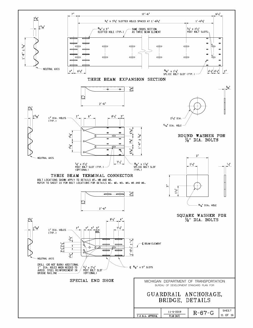
THRIE BEAM EXPANSION SECTION
4"
SPLICE BOLT SLOT (TYP.)
x 1„" 4‚" 4‚" 2"
6‚"
1'-6ƒ"
AS THRIE BEAM ELEMENT
SAME CROSS SECTION
POST BOLT SLOTS
ƒ" x 2•"
7" 12'-6"
ƒ" x 3ƒ" SLOTTED HOLES SPACED AT 1'-6ƒ"
SLOTTED HOLE (TYP.)
x 5"
‡" DIA. BOLTS
ROUND WASHER FOR
•" DIA. HOLE
2‚" DIA.
’"
‡" DIA. BOLTS
SQUARE WASHER FOR
•" DIA. HOLE
‚"
3"
1•"
3"
1•
"
3"+
2"
8•"
7‚"3"
MIN.
3…"
2'-6"
4"4"
(TYP.)
1" DIA. HOLES1˜"
4"
3…
"
BRIDGE RAILING
AVOID STEEL REINFORCEMENT IN
1" DIA. HOLES WHEN NEEDED TO
DRILL (DO NOT BURN) ADDITIONAL
1ƒ
"
3•
"3•
"
1ƒ
"
NEUTRAL AXIS
1'-0‚
"
+ ‚
"7†
"6
‰"
6‰
"
1'-8"
+
‰"
3…
"
3"+
3"8•"2" 8"
2'-6"
7†
"7†
"
3…"
1˜"
NEUTRAL AXIS
7‚"
SPECIAL END SHOE
\ BEAM ELEMENT
\ x 5" SLOTS
(OPTIONAL)
POST BOLT SLOT
ƒ" x 2•"
16
(TYP.)
1" DIA. HOLES
(OPTIONAL)
POST BOLT SLOT (TYP.)
ƒ" x 2•"
(TYP.)
SPLICE BOLT SLOT
x 1„"
THRIE BEAM TERMINAL CONNECTOR
REFER TO SHEET 15 FOR BOLT LOCATIONS FOR DETAILS M1, M2, M3, M4, M5 AND M6.
BOLT LOCATIONS SHOWN APPLY TO DETAILS M7, M8 AND M9.
MICHIGAN DEPARTMENT OF TRANSPORTATION
OF
SHEET
PLAN DATEF.H.W.A. APPROVAL
BUREAU OF DEVELOPMENT STANDARD PLAN FOR
BRIDGE, DETAILS
GUARDRAIL ANCHORAGE,
R-67-G11-6-2019
12
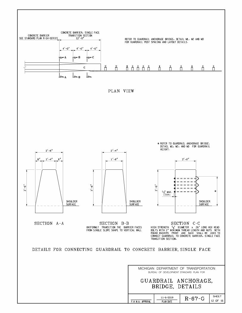
SECTION A-A
3'-6"
2'-8"
1'-4"8" 8" 2'-0"
3'-6"
3'-6"
2'-4"
1'-8"
SURFACE
SHOULDER
SURFACE
SHOULDER
SURFACE
SHOULDER
SECTION B-B SECTION C-C
DETAILS FOR CONNECTING GUARDRAIL TO CONCRETE BARRIER, SINGLE FACE
BA C
BA
C
4'-0"
(TYP)
•" MAX.
12'-0"
TRANSITION SECTION
CONCRETE BARRIER, SINGLE FACE
SEE STANDARD PLAN R-54-SERIES
CONCRETE BARRIER
FROM SINGLE SLOPE SHAPE TO VERTICAL WALL
UNIFORMLY TRANSITION THE BARRIER FACES
4'-0"4'-0"
TRANSITION SECTION.
CONNECT GUARDRAIL TO CONCRETE BARRIER, SINGLE FACE
ROUND WASHERS FRONT AND BACK SHALL BE USED TO
BOLTS WITH 2" MINIMUM THREAD LENGTH AND NUTS WITH
HIGH STRENGTH ‡" DIAMETER x 26" LONG HEX HEAD
PLAN VIEW
16
FOR GUARDRAIL POST SPACING AND LAYOUT DETAILS.
REFER TO GUARDRAIL ANCHORAGE BRIDGE, DETAIL M1, M2 AND M3
*
HEIGHT.
DETAIL M1, M2, AND M3 FOR GUARDRAIL
* REFER TO GUARDRAIL ANCHORAGE BRIDGE,
BRIDGE, DETAILS
GUARDRAIL ANCHORAGE,
R-67-G11-6-2019
13
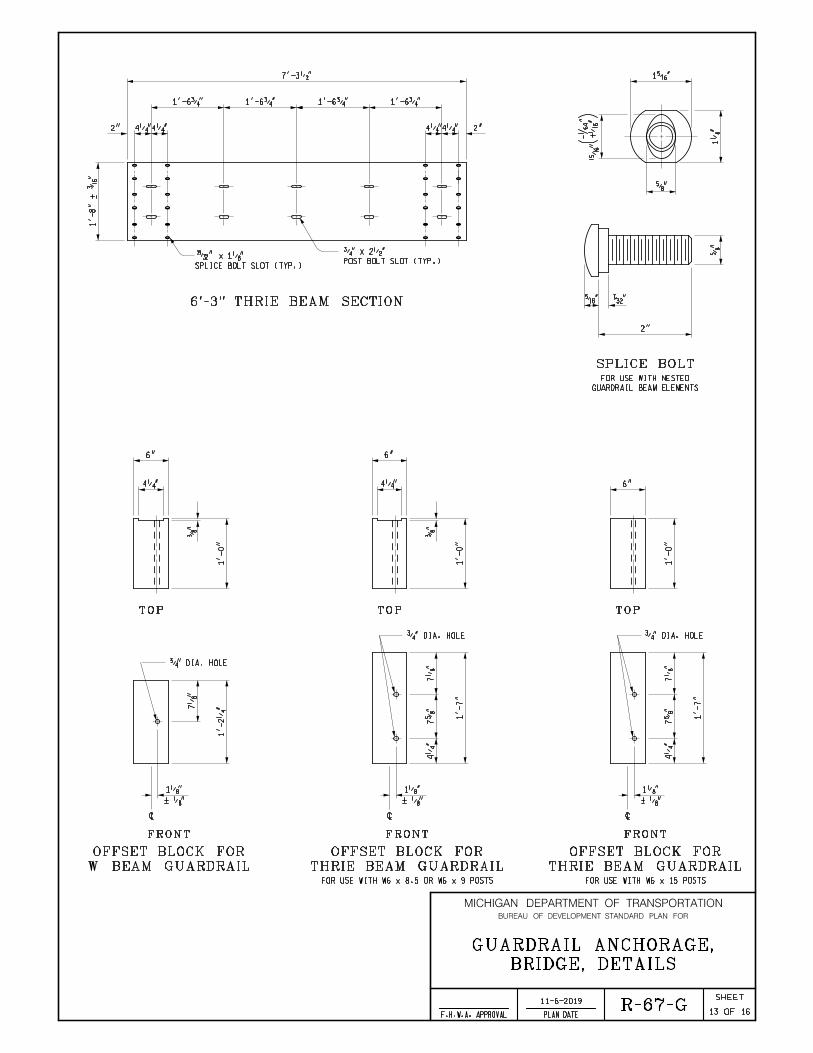
4‚"4‚" 2"4‚"4‚"2"
7'-3•"
1'-6ƒ" 1'-6ƒ"
1'-8"
+
‰"
POST BOLT SLOT (TYP.)
ƒ" x 2•"
SPLICE BOLT SLOT (TYP.)
x 1„"
1'-6ƒ" 1'-6ƒ"
6'-3" THRIE BEAM SECTION
7„
"
1'-2‚
"1'-0"
TOP
FRONT
W BEAM GUARDRAIL
OFFSET BLOCK FOR
FRONT
THRIE BEAM GUARDRAIL
OFFSET BLOCK FOR
TOP
Š" “"
2"
†"
†"
1„
"
1Š"
)•
"+ˆ
"
-
"
SPLICE BOLT
GUARDRAIL BEAM ELEMENTS
FOR USE WITH NESTED
16
…"
6"
4‚"
ƒ" DIA. HOLE
1'-0"
…"
6"
4‚"
7„
"
1'-7"
7†
"4‚
"
FRONT
THRIE BEAM GUARDRAIL
OFFSET BLOCK FOR
ƒ" DIA. HOLE
TOP
1'-0"
6"
7„
"
1'-7"
7†
"4‚
"
FOR USE WITH W6 x 15 POSTSFOR USE WITH W6 x 8.5 OR W6 x 9 POSTS
1„"
< „"
\
1„"
< „"
\
ƒ" DIA. HOLE
1„"
< „"
\
MICHIGAN DEPARTMENT OF TRANSPORTATION
OF
SHEET
PLAN DATEF.H.W.A. APPROVAL
BUREAU OF DEVELOPMENT STANDARD PLAN FOR

BRIDGE, DETAILS
GUARDRAIL ANCHORAGE,
R-67-G11-6-2019
14
3•"
ƒ"
7†
"7
‰"
5‡"
7'-0"
6"
FRONT SIDE FRONT SIDE
W6 x 15 POST
W6 x 8.5 POST
W6 x 9 OR
TOP TOP
6"
ƒ" DIA. HOLE *
GUARDRAIL
WITH THRIE BEAM
* BOTTOM HOLE FOR USE
6'-0"
OR 7'-0"
16
(OPTIONAL)
GALVANIZING HOLE
2"
TO 3"
(OPTIONAL)
GALVANIZING HOLE
2"
TO 3"
7†
"7
‰"
ƒ" DIA. HOLE
1‡"
MICHIGAN DEPARTMENT OF TRANSPORTATION
OF
SHEET
PLAN DATEF.H.W.A. APPROVAL
BUREAU OF DEVELOPMENT STANDARD PLAN FOR
MICHIGAN DEPARTMENT OF TRANSPORTATION
OF
SHEET
PLAN DATEF.H.W.A. APPROVAL
BUREAU OF DEVELOPMENT STANDARD PLAN FOR
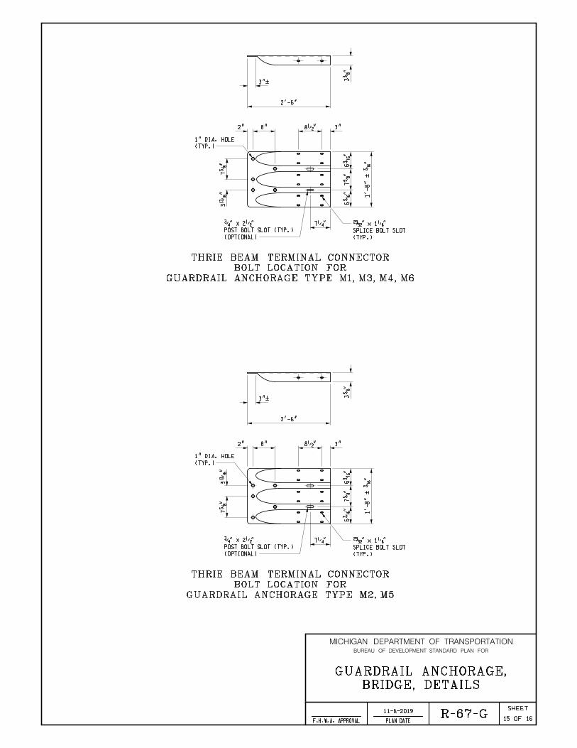
7†
"6
‰"
6‰
"
1'-8"
<
‰"
8•"8"2"
7‚"7†
"3
Ž"
3"
2'-6"
3"<
3…
"
(TYP.)
SPLICE BOLT SLOT
ž" x 1„"
(OPTIONAL)
POST BOLT SLOT (TYP.)
ƒ" x 2•"
(TYP.)
1" DIA. HOLE
GUARDRAIL ANCHORAGE TYPE M1, M3, M4, M6
BOLT LOCATION FOR
THRIE BEAM TERMINAL CONNECTOR
7†
"6
‰"
6‰
"
1'-8"
<
‰"
8•"8"2"
7‚"
7†
"3
Ž"
3"
2'-6"
3"<
3…
"
(TYP.)
SPLICE BOLT SLOT
ž" x 1„"
(OPTIONAL)
POST BOLT SLOT (TYP.)
ƒ" x 2•"
(TYP.)
1" DIA. HOLE
GUARDRAIL ANCHORAGE TYPE M2, M5
BOLT LOCATION FOR
THRIE BEAM TERMINAL CONNECTOR
BRIDGE, DETAILS
GUARDRAIL ANCHORAGE,
R-67-G11-6-2019
15 16
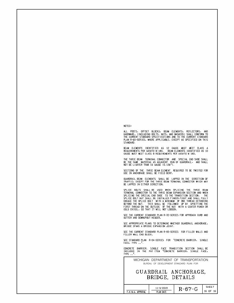
BRIDGE SPANS A BRIDGE EXPANSION JOINT.
SEE APPROPRIATE PLANS TO DETERMINE WHETHER GUARDRAIL ANCHORAGE,
FILLER WALL END BLOCK.
SEE THE CURRENT STANDARD PLAN R-55-SERIES FOR FILLER WALLS AND
BE LAPPED IN EITHER DIRECTION.
TRAFFIC, EXCEPT FOR THE THRIE BEAM TERMINAL CONNECTOR WHICH MAY
GUARDRAIL BEAM ELEMENTS SHALL BE LAPPED IN THE DIRECTION OF
USE IN ANCHORAGE SHALL BE FIELD BENT.
SECTIONS OF THE THRIE BEAM ELEMENT REQUIRED TO BE TWISTED FOR
STANDARD.
PLAN R-60-SERIES, WHERE APPLICABLE, EXCEPT AS SPECIFIED ON THIS
THE CURRENT STANDARD SPECIFICATIONS AND TO THE CURRENT STANDARD
HARDWARE, (INCLUDING BOLTS, NUTS, AND WASHERS) SHALL CONFORM TO
ALL POSTS, OFFSET BLOCKS, BEAM ELEMENTS, REFLECTORS, AND
NOTES:
FACE, TYPE __".
SEE STANDARD PLAN R-54-SERIES FOR "CONCRETE BARRIER, SINGLE
TYPE __".
INCLUDED IN THE PAY ITEM "CONCRETE BARRIER, SINGLE FACE,
CONCRETE BARRIER, SINGLE FACE TRANSITION SECTION SHALL BE
MICHIGAN DEPARTMENT OF TRANSPORTATION
OF
SHEET
PLAN DATEF.H.W.A. APPROVAL
BUREAU OF DEVELOPMENT STANDARD PLAN FOR
BRIDGE, DETAILS
GUARDRAIL ANCHORAGE,
R-67-G11-6-2019
16 16
GAUGE MUST MEET CLASS B REQUIREMENTS PER AASHTO M 180.
REQUIREMENTS PER AASHTO M 180. BEAM ELEMENTS IDENTIFIED AS 10
BEAM ELEMENTS IDENTIFIED AS 12 GAUGE MUST MEET CLASS A
GUTTER AND DOWNSPOUT HEADER.
SEE THE CURRENT STANDARD PLAN R-32-SERIES FOR APPROACH CURB AND
COLD CHISEL, SO THAT IT WILL NOT LOOSEN.
FIRST THREAD ON THE OUTSIDE OF THE NUT WITH A CENTER PUNCH OR
BEYOND THE NUT. THIS SHALL BE FOLLOWED UP BY UPSETTING THE
ENGAGE THE SPLICE BOLT WITH A MINIMUM OF ONE THREAD EXTENDING
SPLICE BOLT NUT SHALL BE INSTALLED FINGER-TIGHT AND SHALL FULLY
SPLICING THE SPECIAL END SHOE TO THE TRANSITION SECTION. THE
TERMINAL CONNECTOR TO THE THRIE BEAM EXPANSION SECTION AND WHEN
SPLICE BOLTS SHALL BE USED WHEN SPLICING THE THRIE BEAM
NOT BE LIGHTER THAN 10 GAUGE (0.138").
BE THE SAME MATERIAL AS ADJACENT RUN OF GUARDRAIL, AND SHALL
THE THRIE BEAM TERMINAL CONNECTOR AND SPECIAL END SHOE SHALL

DEPARTMENT DIRECTOR MICHIGAN DEPARTMENT OF TRANSPORTATION
OF
SHEET
PLAN DATEF.H.W.A. APPROVALCHECKED BY:
DRAWN BY:
Michigan Department of Transportation
BUREAU OF DEVELOPMENT SPECIAL DETAIL FOR
APPROVED BY:
APPROVED BY:
Paul C. Ajegba
BY
PREPARED
DESIGN DIVISION
DIRECTOR, BUREAU OF FIELD SERVICES
DIRECTOR, BUREAU OF DEVELOPMENT 1
BRIDGE, DETAILS
GUARDRAIL ANCHORAGE,
RAILING
BRIDGE BARRIER
E3 JOINT
PO
ST 6
PO
ST 5
PO
ST 4
PO
ST 3
PO
ST 2
PO
ST 1
PLAN VIEW
15"
(4 SPACES) (3 SPACES)
3'-1•" POST SPACING
25'-0"
10'-7•"
POST SPACING
6'-3"
3'-6" POST SPACING
1'-6ƒ"
ELEVATION VIEW
THRIE BEAM EXPANSION SECTION
BRIDGE BARRIER RAILING
THRIE BEAM TERMINAL CONNECTOR
34"
15"
(4 SPACES) (3 SPACES)
3'-1•" POST SPACING 6'-3" POST SPACING
(2 SPACES)
3'-6" POST SPACING
1'-6ƒ"
10'-7•"
34"
28"33"
THRIE BEAM EXPANSION SECTIONTHRIE BEAM TERMINAL CONNECTOR
BRIDGE BARRIER RAILING
ELEVATION VIEW
(TO BE USED WITH GUARDRAIL, TYPE B)
(WITHOUT EXPANSION AT BACKWALL)
6'-3" TYPICAL POST SPACING
GUARDRAIL, TYPE T
GUARDRAIL, TYPE MGS-8 *
INFORMATION)
FOR TYPE MGS-8 GUARDRAIL HEIGHT
(SEE STANDARD PLAN R-60-SERIES
34" TYPE T
(TO BE USED WITH GUARDRAIL, TYPE T & TYPE MGS-8)
AESTHETIC PARAPET TUBE, OR 3 TUBE WITH PICKETS
BRIDGE BARRIER RAILINGS, TYPE 4, 2-TUBE, 4-TUBE,
DETAILS FOR CONNECTING GUARDRAIL TO
6'-3" TYPICAL POST SPACING
GUARDRAIL, TYPE B
31'-3"
10 GAUGE
TRANSITION
THRIE BEAM
SYMMETRICAL
6'-3"25'-0"
11-13-2019
7
10 GAUGE
THRIE BEAM SECTIONS
10 GAUGE
THRIE BEAM SECTIONS
GUARDRAIL ANCHORAGE, BRIDGE, DETAIL T1 (SEE NOTES, SHEET 20)
ANCHORAGE, BRIDGE DETAILS T1, T4 & T6
FROM GUARDRAIL, TYPE MGS-8 TO GUARDRAIL
SPACING AND GUARDRAIL LAYOUT TO TRANSITION
* SEE STANDARD PLAN R-60-SERIES FOR POST
GUARDRAIL ANCHORAGE, BRIDGE, DETAIL T2 (SEE NOTES, SHEET 20)
B.L.T.
W.K.P. R-67-SD
FOR EXISTING BRIDGE BARRIER RAILINGS
MICHIGAN DEPARTMENT OF TRANSPORTATION
OF
SHEET
PLAN DATEF.H.W.A. APPROVAL
BUREAU OF DEVELOPMENT SPECIAL DETAIL FOR
PO
ST 1
PO
ST 2
PO
ST 3
PO
ST 4
PO
ST 5
PO
ST 6
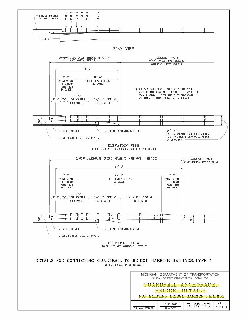
RAILING, TYPE 5
BRIDGE BARRIER
PLAN VIEW
E3 JOINT
(4 SPACES) (3 SPACES)
3'-1•" POST SPACING3'-6" POST SPACING
1'-6ƒ"
15"
ELEVATION VIEW
SPECIAL END SHOE
BRIDGE BARRIER RAILING, TYPE 5
30"
(WITHOUT EXPANSION AT BACKWALL)
DETAILS FOR CONNECTING GUARDRAIL TO BRIDGE BARRIER RAILINGS, TYPE 5
(TO BE USED WITH GUARDRAIL, TYPE B)
ELEVATION VIEW
33"
34"
BRIDGE BARRIER RAILING, TYPE 5
SPECIAL END SHOE
30"
(4 SPACES) (3 SPACES)
3'-1•" POST SPACING 6'-3" POST SPACING
(2 SPACES)
6'-3" TYPICAL POST SPACING
37'-6"
3'-6" POST SPACING
1'-6ƒ"
15"
28"
6'-3" TYPICAL POST SPACING
GUARDRAIL, TYPE T
GUARDRAIL, TYPE B
GUARDRAIL, TYPE MGS-8 *
INFORMATION)
FOR TYPE MGS-8 GUARDRAIL HEIGHT
(SEE STANDARD PLAN R-60-SERIES
34" TYPE T
(TO BE USED WITH GUARDRAIL, TYPE T & TYPE MGS-8)
GUARDRAIL ANCHORAGE, BRIDGE, DETAIL T3 (SEE NOTES, SHEET 20)
25'-0"
10 GAUGE
TRANSITION
THRIE BEAM
SYMMETRICAL
6'-3"
10 GAUGE
TRANSITION
THRIE BEAM
SYMMETRICAL
6'-3"
10 GAUGE
TRANSITION
THRIE BEAM
SYMMETRICAL
6'-3" 12'-6"
18'-9"
10 GAUGE
THRIE BEAM SECTION
10 GAUGE
THRIE BEAM SECTIONS
THRIE BEAM EXPANSION SECTION
THRIE BEAM EXPANSION SECTION
(SEE NOTES, SHEET 20)
GUARDRAIL ANCHORAGE, BRIDGE, DETAIL T4
ANCHORAGE, BRIDGE DETAILS T1, T4 & T6
FROM GUARDRAIL, TYPE MGS-8 TO GUARDRAIL
SPACING AND GUARDRAIL LAYOUT TO TRANSITION
* SEE STANDARD PLAN R-60-SERIES FOR POST
BRIDGE, DETAILS
GUARDRAIL ANCHORAGE,
11-13-2019
7R-67-SD
FOR EXISTING BRIDGE BARRIER RAILINGS
2

PO
ST 1
PO
ST 2
PO
ST 3
PO
ST 4
PO
ST 5
PO
ST
6
RAILING, TYPE 4
BRIDGE BARRIER
PLAN VIEW
E3 JOINTEXPANSION JOINT
BRIDGE
(WITH EXPANSION AT BACKWALL)
(TO BE USED WITH GUARDRAIL, TYPE B)
ELEVATION VIEW
THRIE BEAM EXPANSION SECTION
34"
THRIE BEAM TERMINAL CONNECTOR
BRIDGE BARRIER RAILING, TYPE 4
34"
32"
16"
(4 SPACES) (4 SPACES)
3'- 1•" POST SPACING
MAX (2 SPACES)
6'-3" POST SPACING
6'-3" TYPICAL POST SPACING
43'-9"
7'-10•" 6'-3" 12'-6"
3'-6"
MIN.
POST SPACING
1'-6ƒ"
ELEVATION VIEW
THRIE BEAM EXPANSION SECTIONTHRIE BEAM TERMINAL CONNECTOR
BRIDGE BARRIER RAILING, TYPE 4
34"
16"
(4 SPACES) (4 SPACES)
3'-1•" POST SPACING
MAX
25'-0"
7'-10•" 6'-3" 12'-6"
POST SPACING
1'-6ƒ"
3'-6"
MIN.
28"
GUARDRAIL, TYPE B
6'-3" TYPICAL POST SPACING
GUARDRAIL, TYPE T
(TO BE USED WITH GUARDRAIL, TYPE T & TYPE MGS-8)
GUARDRAIL, TYPE MGS-8 *
INFORMATION)
FOR TYPE MGS-8 GUARDRAIL HEIGHT
(SEE STANDARD PLAN R-60-SERIES
34" TYPE T
AESTHETIC PARAPET TUBE, OR 3 TUBE WITH PICKETS
BRIDGE BARRIER RAILINGS, TYPE 4, 2-TUBE, 4-TUBE,
DETAILS FOR CONNECTING GUARDRAIL TO
10 GAUGE
TRANSITION
THRIE BEAM
SYMMETRICAL
6'-3"37'-6"
GUARDRAIL ANCHORAGE, BRIDGE, DETAIL T5 (SEE NOTES, SHEET 20)
GUARDRAIL ANCHORAGE, BRIDGE, DETAIL T1 (SEE NOTES, SHEET 20)
10 GAUGE
THRIE BEAM SECTIONS
10 GAUGE
THRIE BEAM SECTIONS
ANCHORAGE, BRIDGE DETAILS T1, T4 & T6
FROM GUARDRAIL, TYPE MGS-8 TO GUARDRAIL
SPACING AND GUARDRAIL LAYOUT TO TRANSITION
* SEE STANDARD PLAN R-60-SERIES FOR POST
BRIDGE, DETAILS
GUARDRAIL ANCHORAGE,
11-13-2019
7R-67-SD
FOR EXISTING BRIDGE BARRIER RAILINGS
3
MICHIGAN DEPARTMENT OF TRANSPORTATION
OF
SHEET
PLAN DATEF.H.W.A. APPROVAL
BUREAU OF DEVELOPMENT SPECIAL DETAIL FOR

15"
3'-1•" POST SPACING
34"
34"
15" 3'- 1•" POST SPACING
32"
28"
(4 OR 5 SPACES) (3 OR 4 SPACES)
32"
SEE APPROACH POST SPACING REQUIREMENTS CHART
PIER
BRIDGE
FIRST POST
CONNECTOR
TERMINAL
THRIE BEAM
(4 OR 5 SPACES) (3 OR 4 SPACES)
6'-3" TYPICAL POST SPACING
PIER
BRIDGE
3'-1•"
FIRST POST
CONNECTOR
TERMINAL
THRIE BEAM
SEE APPROACH POST SPACING REQUIREMENTS CHART
6'-3" TYPICAL POST SPACING
PIER
BRIDGE
FILLER WALL END BLOCK
AND FILLER WALLS, SHEET 5 OF 7)
REQUIREMENTS FOR CONNECTING GUARDRAIL TO BRIDGE RAILINGS
INSTALL BOLTS THROUGH FILLER WALL (SEE CHART FOR BOLT
BOLTS TO FIRST POST
DISTANCE FROM ANCHOR7'-11ƒ" 11'-1‚"
4
4
5
3
4
3
PLAN VIEW
ELEVATION VIEW
ELEVATION VIEW
DETAILS FOR CONNECTING GUARDRAIL TO FILLER WALLS
APPROACH POST SPACING REQUIREMENTS
GUARDRAIL, TYPE TGUARDRAIL ANCHORAGE, BRIDGE, DETAIL T-6 (SEE NOTES, SHEET 7 OF 7)
(TO BE USED WITH GUARDRAIL, TYPE T)
GUARDRAIL, TYPE BGUARDRAIL ANCHORAGE, BRIDGE, DETAIL T-5 (SEE NOTES, SHEET 7 OF 7)
(TO BE USED WITH GUARDRAIL, TYPE B)
MIN.
MIN.
DEPTH 1'-3" FROM BRIDGE PIER.
POST CAN BE INSTALLED FULL
OMITTED WHEN FIRST ANCHORAGE
NOTE: FILLER WALL END BLOCK MAY BE
POST SPACINGS
NUMBER OF 1'-6ƒ"
POST SPACINGS
NUMBER OF 3'-1•"
9'-6•"
1'-6" POST SPACING
1'-6ƒ"
BLOCKS LESS THAN 3'-0" LONG)
NOT REQUIRED FOR FILLER WALL END
ROUND WASHERS ON BACK (BOLTS ARE
POST BOLT WASHERS ON FRONT AND
TWO †" DIA. x 14" POST BOLTS WITH
POST SPACING
1'-6ƒ"
1'-6"
ELEMENT AS SHOWN ABOVE.
3'-0" OR LONGER, BOLT BEAM
WHEN FILLER WALL END BLOCK IS
BRIDGE, DETAILS
GUARDRAIL ANCHORAGE,
11-13-2019
7R-67-SD
FOR EXISTING BRIDGE BARRIER RAILINGS
4
MICHIGAN DEPARTMENT OF TRANSPORTATION
OF
SHEET
PLAN DATEF.H.W.A. APPROVAL
BUREAU OF DEVELOPMENT SPECIAL DETAIL FOR
10 GAUGE
TRANSITION
THRIE BEAM
SYMMETRICAL
6'-3"
43'-9"
37'-6"
10 GAUGE
THRIE BEAM SECTIONS
37'-6"
10 GAUGE
THRIE BEAM SECTIONS
TYPE 4
TYPE 5
2 TUBE
4 TUBE
FILLER WALL**
5
4
5
5
5
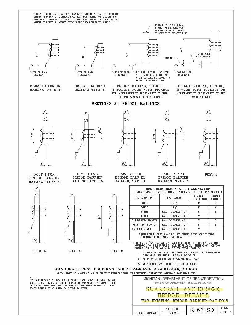
3. WHEN CONDITIONS PROHIBIT THE USE OF BOLTS.
**
34"
34"
VARIABLEOR SIDEWALK
TOP OF CURB
34"
30"
34"
1"
7•"
6•"
3"
6•"
3"
7‚"
BRIDGE RAILING BOLT LENGTHTHREAD LENGTH
MINIMUM
REQUIRED
NUMBER
POST 3
RAILING, TYPE 4
BRIDGE BARRIER
POST 1 FOR
RAILING, TYPE 5
BRIDGE BARRIER
POST 1 FOR
POST 6POST 5POST 4
RAILING, TYPE 4
BRIDGE BARRIER
POST 2 FOR
RAILING, TYPE 5
BRIDGE BARRIER
POST 2 FOR
GUARDRAIL POST SECTIONS FOR GUARDRAIL ANCHORAGE, BRIDGE
GUARDRAIL TO BRIDGE RAILINGS & FILLER WALLS
BOLT REQUIREMENTS FOR CONNECTING
THICKNESS THAN THE FILLER WALL EXTENSION.
1. AT OR NEAR THE JOINT LINE WHEN A FILLER WALL IS A DIFFERENT
NOTE: ADHESIVE ANCHORS SHALL BE SELECTED FROM THE QUALIFIED PRODUCTS LIST OF THE MATERIALS SAMPLING GUIDE.
NUMBER REQUIRED.) WASHER DETAILS ARE SHOWN ON SHEET 6 OF 7.
AND SQUARE WASHERS ON BACK. (SEE CHART BELOW FOR LENGTHS AND
CONNECT GUARDRAIL TO BRIDGE RAILINGS WITH ROUND WASHERS ON FRONT
HIGH STRENGTH ‡" DIA. HEX HEAD BOLT AND NUTS SHALL BE USED TO
8"8"
8" 8" 8"
WALL THICKNESS + 2"
WALL THICKNESS + 2"
WALL THICKNESS + 2"
‚" BEYOND THE NUT WHEN TIGHTENED.
SHORTER BOLT LENGTHS MAY BE USED PROVIDED THE BOLT EXTENDS
4"
4"
2"
2"
2"
8"8"
8"
2. IN EXISTING FILLER WALLS THICKER THAN 1'-6".
1‡" 1•"
2‚"2†"2†"
6" 7"
1'-
10"
1'-
6" 3
Ž"
5…
"
11•"
12•"
1'-
8"
THROUGH THE FILLER WALL, IN THE FOLLOWING LOCATIONS:
GUARDRAIL TO FILLER WALLS WILL BE ALLOWED, INSTEAD OF BOLTING
THE USE OF ‡" DIA. ADHESIVE ANCHORED BOLTS EMBEDDED 8" TO ATTACH
SECTIONS AT BRIDGE RAILINGS
RAILING TYPE 4
BRIDGE BARRIER
RAILING TYPE 5
BRIDGE BARRIER
(WITHOUT SIDEWALK OR BRUSH BLOCK) (WITH SIDEWALK)
(ROADWAY)
TOP OF SLAB
(ROADWAY)
TOP OF SLAB
(ROADWAY)
TOP OF SLAB
(ROADWAY)
TOP OF SLAB
AESTHETIC PARAPET
WALL THICKNESS + 2" 2" 5
BRIDGE, DETAILS
GUARDRAIL ANCHORAGE,
11-13-2019
7R-67-SD
FOR EXISTING BRIDGE BARRIER RAILINGS
5
MICHIGAN DEPARTMENT OF TRANSPORTATION
OF
SHEET
PLAN DATEF.H.W.A. APPROVAL
BUREAU OF DEVELOPMENT SPECIAL DETAIL FOR
AESTHETIC PARAPET TUBE
3 TUBE WITH PICKETS OR
BRIDGE RAILING, 4 TUBE,
OR AESTHETIC PARAPET TUBE
4 TUBE, 3 TUBE WITH PICKETS
BRIDGE RAILING, 2 TUBE,
AESTHETIC PARAPET TUBE
PICKETS, DOES NOT APPLY TO
4 TUBE, 8" FOR 3 TUBE WITH
7" FOR 2 TUBE, 9" FOR
TO AESTHETIC PARAPET TUBE
PICKETS, DOES NOT APPLY
4 TUBE, AND 3 TUBE WITH
9" OR LESS FOR 2 TUBE,
SPACING SHALL BE AS SHOWN IN ELEVATION VIEWS.
BRIDGE RAILINGS SHALL BE THE SAME AS THAT SHOWN ON POST 6. POST
THE 2 TUBE, 4 TUBE, 3 TUBE WITH PICKETS AND AESTHETIC PARAPET TUBE
POST AND BLOCK SECTIONS FOR THE SINGLE FACE, CONCRETE BARRIER, AND
NOTE:
5WALL THICKNESS + 2" 2"3 TUBE WITH PICKETS
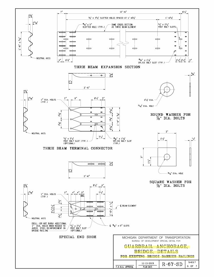
3…"
1˜"
1'-8"
+
‰"
NEUTRAL AXIS8•"
THRIE BEAM EXPANSION SECTION
4"
SPLICE BOLT SLOT (TYP.)
x 1„" 4‚" 4‚" 2"
6‚"
1'-6ƒ"
AS THRIE BEAM ELEMENT
SAME CROSS SECTION
POST BOLT SLOTS
ƒ" x 2•"
7" 12'-6"
ƒ" x 3ƒ" SLOTTED HOLES SPACED AT 1'-6ƒ"
SLOTTED HOLE (TYP.)
x 5"
‡" DIA. BOLTS
ROUND WASHER FOR
•" DIA. HOLE
2‚" DIA.
’"
‡" DIA. BOLTS
SQUARE WASHER FOR
•" DIA. HOLE
‚"
3"
1•"
3"
1•
"
3"+
2"
8•"
7‚"3"
MIN.
3…"
2'-6"
4"4"
(TYP.)
1" DIA. HOLES1˜"
4"
3…
"
BRIDGE RAILING
AVOID STEEL REINFORCEMENT IN
1" DIA. HOLES WHEN NEEDED TO
DRILL (DO NOT BURN) ADDITIONAL
1ƒ
"
3•
"3•
"
1ƒ
"
NEUTRAL AXIS
1'-0‚
"
+ ‚
"7†
"6
‰"
6‰
"
1'-8"
+
‰"
3…
"
3"+
3"8•"2" 8"
2'-6"
7†
"7†
"
3…"
1˜"
NEUTRAL AXIS
7‚"
SPECIAL END SHOE
\ BEAM ELEMENT
\ x 5" SLOTS
(OPTIONAL)
POST BOLT SLOT
ƒ" x 2•"
(TYP.)
1" DIA. HOLES
(OPTIONAL)
POST BOLT SLOT (TYP.)
ƒ" x 2•"
(TYP.)
SPLICE BOLT SLOT
x 1„"
THRIE BEAM TERMINAL CONNECTOR
BRIDGE, DETAILS
GUARDRAIL ANCHORAGE,
11-13-2019
7R-67-SD
FOR EXISTING BRIDGE BARRIER RAILINGS
6
MICHIGAN DEPARTMENT OF TRANSPORTATION
OF
SHEET
PLAN DATEF.H.W.A. APPROVAL
BUREAU OF DEVELOPMENT SPECIAL DETAIL FOR

BRIDGE SPANS A BRIDGE EXPANSION JOINT.
SEE APPROPRIATE PLANS TO DETERMINE WHETHER GUARDRAIL ANCHORAGE,
FILLER WALL END BLOCK.
SEE THE CURRENT STANDARD PLAN R-55-SERIES FOR FILLER WALLS AND
BE LAPPED IN EITHER DIRECTION.
TRAFFIC, EXCEPT FOR THE THRIE BEAM TERMINAL CONNECTOR WHICH MAY
GUARDRAIL BEAM ELEMENTS SHALL BE LAPPED IN THE DIRECTION OF
USE IN ANCHORAGE SHALL BE FIELD BENT.
SECTIONS OF THE THRIE BEAM ELEMENT REQUIRED TO BE TWISTED FOR
STANDARD.
PLAN R-60-SERIES, WHERE APPLICABLE, EXCEPT AS SPECIFIED ON THIS
THE CURRENT STANDARD SPECIFICATIONS AND TO THE CURRENT STANDARD
HARDWARE, (INCLUDING BOLTS, NUTS, AND WASHERS) SHALL CONFORM TO
ALL POSTS, OFFSET BLOCKS, BEAM ELEMENTS, REFLECTORS, AND
NOTES:
FACE, TYPE __".
SEE STANDARD PLAN R-54-SERIES FOR "CONCRETE BARRIER, SINGLE
TYPE __".
INCLUDED IN THE PAY ITEM "CONCRETE BARRIER, SINGLE FACE,
CONCRETE BARRIER, SINGLE FACE TRANSITION SECTION SHALL BE
GAUGE MUST MEET CLASS B REQUIREMENTS PER AASHTO M 180.
REQUIREMENTS PER AASHTO M 180. BEAM ELEMENTS IDENTIFIED AS 10
BEAM ELEMENTS IDENTIFIED AS 12 GAUGE MUST MEET CLASS A
COLD CHISEL, SO THAT IT WILL NOT LOOSEN.
FIRST THREAD ON THE OUTSIDE OF THE NUT WITH A CENTER PUNCH OR
BEYOND THE NUT. THIS SHALL BE FOLLOWED UP BY UPSETTING THE
ENGAGE THE SPLICE BOLT WITH A MINIMUM OF ONE THREAD EXTENDING
SPLICE BOLT NUT SHALL BE INSTALLED FINGER-TIGHT AND SHALL FULLY
SPLICING THE SPECIAL END SHOE TO THE TRANSITION SECTION. THE
TERMINAL CONNECTOR TO THE THRIE BEAM EXPANSION SECTION AND WHEN
SPLICE BOLTS SHALL BE USED WHEN SPLICING THE THRIE BEAM
NOT BE LIGHTER THAN 10 GAUGE (0.138").
BE THE SAME MATERIAL AS ADJACENT RUN OF GUARDRAIL, AND SHALL
THE THRIE BEAM TERMINAL CONNECTOR AND SPECIAL END SHOE SHALL
W6 x 9) OR WOOD POSTS (6" x 8").
T1 THROUGH T6, SHALL BE 7'-0" LONG STEEL POSTS (W6 x 8.5 OR
ALL POSTS USED TO CONSTRUCT GUARDRAIL ANCHORAGE, BRIDGE, DETAIL
SECTION.
ž" x 5" LONG SLOTTED HOLES IN THE THRIE BEAM EXPANSION
THAT THE THRIE BEAM TERMINAL CONNECTOR BE ATTACHED TO THE
GUARDRAIL ANCHORAGE, BRIDGE, DETAILS T1, T2, AND T5 REQUIRE
BRIDGE, DETAILS
GUARDRAIL ANCHORAGE,
11-13-2019
7R-67-SD
FOR EXISTING BRIDGE BARRIER RAILINGS
7
MICHIGAN DEPARTMENT OF TRANSPORTATION
OF
SHEET
PLAN DATEF.H.W.A. APPROVAL
BUREAU OF DEVELOPMENT SPECIAL DETAIL FOR
MICHIGAN DESIGN MANUAL ROAD DESIGN
5.05
URBAN R.O.W.
Where all or portions of a project are located in urban areas, R.O.W. may be limited to the width determined by municipal planning or to existing R.O.W. Portions within urban boundaries that have never been developed should be set up the same as for rural projects. Occasionally, because of the increased width of the proposed surface, additional R.O.W. is needed. In this case the new width is determined by the Department, and the designer should become familiar with whatever agreements or decisions are made.
5.05.01 (revised 1-29-2018)
Urban Expressways
Right of way is of primary importance in urban expressway design. Modern expressways are designed to provide roadways of sufficient width to carry large volumes of traffic frequently including frontage roads and access ramps, requiring R.O.W. widths of 300' to 400'. Obviously, a strip of land of this width cutting across a city is very costly and disruptive, and the work involved in securing the necessary properties requires a lot of time. Construction that is slowed by R.O.W. acquisition may further be delayed by the moving and razing of many buildings. Base Plans (Preliminary R.O.W.), although not exact and thus subject to revision, should be placed on file in the city's offices and used as a criterion for the issuing of building permits in areas where construction is planned in the near future.
5.05.02 (revised 11-25-2019)
Consent to Construct Sidewalk
Whenever feasible, new or reconstructed sidewalk should be placed 1 foot minimum inside the existing or proposed R.O.W. line (as determined by a Professional Surveyor). When the proposed sidewalk grading limits extend outside the R.O.W., a Consent to Construct Sidewalk (Form 0640C) is requested. The consent obtains permission from and/or gives notice to the adjacent property owner of the Department’s intent to construct new and/or to replace existing sidewalks within the existing or proposed R.O.W. See application #3 on the following page for proposed sidewalk remaining outside the R.O.W. Show slope stake lines to determine the impact to the property.
The Real Estate Services Section of the Development Services Division will determine just compensation for the consent which is offered to the property owner. Consent is noted at each applicable location as:
Consent to Construct Sidewalk
Listed below are several applications for use of the Consent to Construct Sidewalk and options in the event of failure to obtain consent or easements. Gapping out sidewalk construction in areas with consent or easement conflicts is not an acceptable option. Sidewalk accessibility must be provided for persons with disabilities according to the Americans with Disability Act (ADA) of 1990. When constructing sidewalk, the Department is responsible for meeting ADA accessibility requirements for the public sidewalk. The area outside these limits may require restoration of existing private connection to the sidewalk. Regardless of whether or not consent is granted, accessibility impact should be discussed with the property owner during consent negotiations. See Section 6.08.06 for information on accessibility requirements for private connections to sidewalks.

MICHIGAN DESIGN MANUAL ROAD DESIGN
6.01.05 (revised 10-23-2017)
Choice between Aggregate, Hot Mix Asphalt and Concrete
It is the general practice of the Department to not leave aggregate as a driving surface on a roadway. Therefore, at minimum, a new or existing aggregate road will generally be paved with a single course of hot mix asphalt material, regardless of how little traffic it serves.
Michigan differs from many of the states in having a wide range of soil types, varying from well drained sands to heavy clays, to rock outcroppings. Concrete has the advantage of rigidity and high strength relative to thickness and requires less elaborate mixing facilities at the plant. Hot mix asphalt is flexible, easier to repair, and it requires less time to open to traffic, needing only to cool. The Department tries to utilize the advantages of each material when selecting a pavement type.
Ramps will usually have the same type of surfacing as is used on the freeway. One exception would be when the mainline is overlaid utilizing a different wearing surface material than the existing ramp. In this case, the new mainline surface material may extend up the ramps part-way depending on the condition of the ramps.
Similarly, utility trench replacement is typically the same type of pavement material as surrounds it. Refer to section 9.04.01 for design of pavement cross-section replacement due to utility trench work.
6.01.06 (revised 11-25-2019)
Pavement Design and Selection Policy (Approved by EOC 2-9-2012)
A. Design
Pavement design will be performed using design methods outlined in the "Guide for Design of Pavement Structures", AASHTO, 1993. The design software accompanying AASHTO 1993 is the DARWin pavement design program.
B. Selection
Pavement selection will be determined using the life cycle cost analysis method when the project pavement costs exceed the $1.5 million threshold as described in the “Pavement Design and Selection Manual.” Pavement costs are determined by separately calculating the cost of paving with both HMA and concrete. When the cost of either the HMA or concrete exceeds $1.5 million, a life cycle cost analysis is required. For such projects, Pavement Operations of the Construction Field Services Division will conduct the pavement design and life cycle cost analysis in accordance with the “Pavement Design and Selection Manual.” MDOT staff and industry organizations will be provided an opportunity for review and comment, with final approvals by the Engineering Operations Committee. In accordance with state law, the low cost alternative will be selected.
Pavement designs and the life cycle cost analysis will be done by Pavement Operations for the following project categories.
a. All new/reconstruction projects with pavement costs greater than $1.5 million
b. Major rehabilitation projects (unbonded concrete overlays & rubblized with HMA surfacing) with pavement costs greater than $1.5 million.

MICHIGAN DESIGN MANUAL ROAD DESIGN
6.06.06C (continued)
Criteria for Use
Detail F - Detail F curb and gutter may be used where a high profile mountable curb is desired and the design speed is 50 mph (45 mph posted) or less. Typical usage would be in areas where Detail C curb and gutter is being replaced or where Detail B or Detail D curb and gutter would not yield sufficient roadside control.
Detail G - Detail G curb and gutter is to be used on urban freeways. See Section 6.06.10.
D. Unlighted Areas
Generally speaking, it is undesirable to introduce or to use a curb, immediately adjacent to the roadway, in unlighted areas.
6.06.07
Deleted
6.06.08 (revised 11-25-2019)
Bridge Approach Curb and Gutter
The type, length, and method of drainage at bridge approaches is the responsibility of the bridge designer. The quantities, however, are included in the road plans when road plans are involved.
The designer will need to meet the design spread requirements in the Drainage Manual, including 100% capture (no bypass flows) during the design event at locations where the curbing ends at the approaches to reduce the risk of erosion of the road embankment. The actual spacing and type of drainage capture device (downspout, catch basin, spillway) will be site specific.
Following is a guide to the use of the bridge approach curb and gutter details shown on Standard Plan R-32-Series with a 4” maximum curb height. It should be emphasized that this criteria is only a guide and that the designer should use engineering judgement in determining the type of structure to use.
Detail 5 - Used on the high ends of bridges where the bridge runoff drains toward the bridge or on the departing ends of bridges when guardrail is not needed.
Detail 6 (and 6A) - Used on the low ends of bridges where moderate amounts of drainage area are involved (<2500 sft of paved area draining to the curb and gutter) and fills are less than 10’ high.
Detail 7 (and 7A) - Used on the low ends of bridges where greater amounts of drainage may be expected (>2500 Sft of paved area draining to the curb and gutter) and in fills greater than 10’ high. One downspout header should be provided for each 3500 sft (approximately) of paved runoff areas or fraction thereof. If it is not readily apparent whether to use Detail 6 or Detail 7, use Detail 7.
If the bridge railing is other than the standard shape, the approach curb and gutter should be modified or transitioned to fit the bridge curb.

MICHIGAN DESIGN MANUAL ROAD DESIGN
12.10.08 (revised 11-25-2019)
Portable Intermittent Truck Weigh Stations (PITWS) General Information
SITE SELECTION
In considering the safety of officers and passing motorists, the desired order of preference for new PITWS locations is in a rest area, a recognized Safe Enforcement Site, MDOT and county garages, carpool parking lots.
PITWS will not be permitted on a freeway shoulder. Due to traffic volume, PITWS will not be installed in the shoulder of any road unless supported by a low ADT, or installed in a recognized Safe Enforcement Site.
PITWS will not be permitted in the mainline.
The finished site must allow a minimum 3’ safe working area on all sides of a target vehicle. This area must be a reasonable grade and levelness, allowing the officer to operate safely around the target vehicle with a 12’ work area on the vehicle travel side.
Concrete pads less than 200’ shall not be installed in asphalt. However, concrete pads of at least 60’ may be installed into asphalt with a concrete base with proper anchoring into the existing concrete base.
GENERAL REQUIREMENTS
PITWS LOCATION: In all cases, the PITWS shall be centered
within the joint spacing.
LANE WIDTH: A minimum of 12’, with 14’ being desirable
not including work area. See SITE SELECTION.
LANE LENGTH: The desirable length of straight pavement
is 200’ (100’ on either side of the PITWS), not including approach and departure tapers, with a minimum length of 60’ (30’ on either side of the PITWS).
12.10.08 (continued)
PAVEMENT COMPOSITE & THICKNESS: It is recommended that the area meet or
exceed the thickness and composite specifications of the existing pavement slab.
New slabs, not proximate to any pavement, shall be designed consistent with the current full depth mainline concrete pavement standards.
CONCRETE REINFORCEMENT: Reinforcement is not required or
recommended, except at concrete joints, particularly in the center slab where the cut out will be located.
Concrete anchoring between poured slabs is REQUIRED on all new concrete, and between new concrete and existing concrete. All cut locations must be projected prior to pour so that proper reinforcement can be installed.
TAPER(S): Adequate tapers must be provided, before
and after the desired 200’ of straight pavement, to allow the vehicle to remain straight while on the pad. Vehicles approaching and/or leaving the 200’ pad in a straight-line need no taper(s).
Generally, 100’ of taper into the straight approach pad and 100’ of departure taper beyond the departure pad is recommended.
LEVELNESS: A concrete scale pad shall not be placed
in a vertical curve section. The desired area 100’ on both sides of the scale trench shall be preferably in one plane and within the specified grades.
MICHIGAN DESIGN MANUAL ROAD DESIGN
12.10.08 (continued)
Portable Intermittent Truck Weigh Stations (PITWS) General Information
GRADE: Lateral - A zero grade is desirable, with a
maximum of 5%. Longitudinal – For newly placed slabs, as
close to a flat grade as possible is recommended to maintain stationary vehicles without brakes being applied, up to a maximum of 2%. For existing slabs a maximum of 2% is recommended.
CONDITION: All pavements, new and existing, must be
free of cracks, bumps or dips that may cause distinct elevation changes.
SMOOTHNESS Pavement surface must be level within
± 1/16” from center of slab to 30’ in either direction. The remainder of the pavement (excluding tapers) must be within ± 3/16”.
Pavement surface should receive a light broom finish. Tining is not recommended.
PAVEMENT REMOVAL (if applicable): Pavement removal, replacement,
reinforcement, and tied joint, when specified shall meet current MDOT design specifications, unless otherwise noted.
Regardless of depth, all pavement removal will be included in the pay item “Pavt, Rem”.
Standard pay items should be used for payment, however modification may be required in order to meet the requirements of this section.
12.10.08 (continued)
PITWS Inspection: Contact CVST for inspection of PITWS.
MICHIGAN DESIGN MANUAL BRIDGE DESIGN
7.02.27
Sidewalks (9-2-2003) (11-25-2019)
In general, on a bridge where pedestrians must be accommodated and where maximum posted speed is 40 mph or less, a raised sidewalk should be provided if there is a raised sidewalk on the approach. Where posted speed is greater than 40 mph or there is no raised sidewalk on the approach, a walkway at roadway level should be provided and protected from traffic by an MDOT approved bridge railing.
Where sidewalks are required, they should be 5'-2" or greater in width. However, in circumstances where a 5'-2" width is not achievable a 4'-2" minimum width is permissible if crash tests allow. (11-28-2011)
When the bridge railing length is greater than 200 feet, to adhere to Americans with Disabilities Act (ADA), the sidewalk must be 5’-0” wide (@ 2% slope) or a 5’ square passing space shall be located at intervals not exceeding 200 feet. The requirement is valid with a raised sidewalk as on Standard Plan B25Series, B26Series or B-27-Series and anywhere where the sidewalk is located behind a railing that separates pedestrians from traffic. For railing lengths less than 200 feet the sidewalk width may be 4’-2” if crash tests allow and does not require passing spaces. (11-28-2011)
Expansion joints located on sidewalks shall be fitted with cover plates to eliminate vertical depressions caused by the joint. See Expansion Joint sheets (EJ3 or EJ4). (11-28-2011)
For additional information, refer to Bridge Design Guides 6.05.02, 6.29.10C, 6.29.17Eand Road Design Manual Section 6.08.
7.02.27 (continued)
A. Sidewalk Joints
Space sidewalk joints to match any joints in the slab. (9-25-2017)
B. Independent Sidewalk
If the sidewalk is independent of the roadway slab, the sidewalk is to be designed for maximum wheel loading for the bridge with overstressing as allowed by the current AASHTO Standard Specifications for Highway Bridges.
MICHIGAN DESIGN MANUAL BRIDGE DESIGN
7.02.28
Railing (9-2-2003) (11-25-2019)
Where bridge railing is to be installed, and there are no sidewalks or the sidewalk is behind the railing, the railing shall be one of the bridge railing types currently approved for use by MDOT. The only types of railings currently used by MDOT are the Type 6 Barrier (see Standard Plan B-29-Series), Type 7 Barrier (see Standard Plan B-28-Series), the 2 Tube railing (see Standard Plan B21Series), 4 Tube railing (see Standard Plan B-26-series), Aesthetic Parapet Tube railing (see Standard Plan B-25-Series) and 3 Tube With Pickets (see Standard Plan B27Series).
Where bridge railing is to be installed on raised sidewalks it must be 4 Tube railing (see Standard Plan B-26-series) Aesthetic Parapet Tube railing (see Standard Plan B25Series) or 3 Tube With Pickets (see Standard Plan B27-Series).
A. Railing Types and Their Use (9-2-2003) (11-25-2019)
Generally, Bridge Barrier Railing, Type 6, is used on all new structures and reconstruction (major rehabilitation) bridge projects without sidewalks (see Standard Plan B-29-Series). On structures where sight distance or clear roadway width is a problem, Type 7 may be substituted (see Standard Plan B-28-Series). At stream crossings or scenic areas, Bridge Railing, 2 Tube, Aesthetic Parapet Tube, 4 Tube or 3 Tube With Pickets may be used (see Standard Plan B-21-Series, B-25-Series, B-26-Series or B-27-Series). On bridges where pedestrian or bicycle traffic is separated from vehicular traffic by a standard barrier, it is not necessary to provide a vehicular railing at the fascias. In such cases pedestrian fencing is desirable.
For structures without sidewalks, but where some pedestrian traffic is likely, a Bridge Railing, 4 Tube, Aesthetic Parapet Tube or 3 Tube With Pickets is to be used.
7.02.28 (continued)
B. Railing Finishes
A rubbed surface finish is required for concrete railings on all bridges with sidewalks and left turn bridges in urban areas.
Note 8.07.01E is to be included in the plans of all projects where a rubbed finish is required. It is to be placed on the same sheet and directly under the note making reference to the railing standard being used.
C. Joints
To avoid cracking, an open joint is required in concrete railings at all deck joints where reinforcing steel is not continued through the joint. False joints are not required in barrier railing.
A 1" joint shall be used in all concrete railings over the piers of continuous decks, at midspan on all structures with a span greater than 100'-0" and cantilever decks where the cantilever is more than 10'-0” long. The joint shall be perpendicular to the centerline even on skewed bridges. A 1" joint filler shall be used to fill the joint to ½” from the bevels of the railing. The remaining ½” shall be sealed with a polyurethane or polyurethane hybrid sealant. (5-1-2000) (2-21-2017)
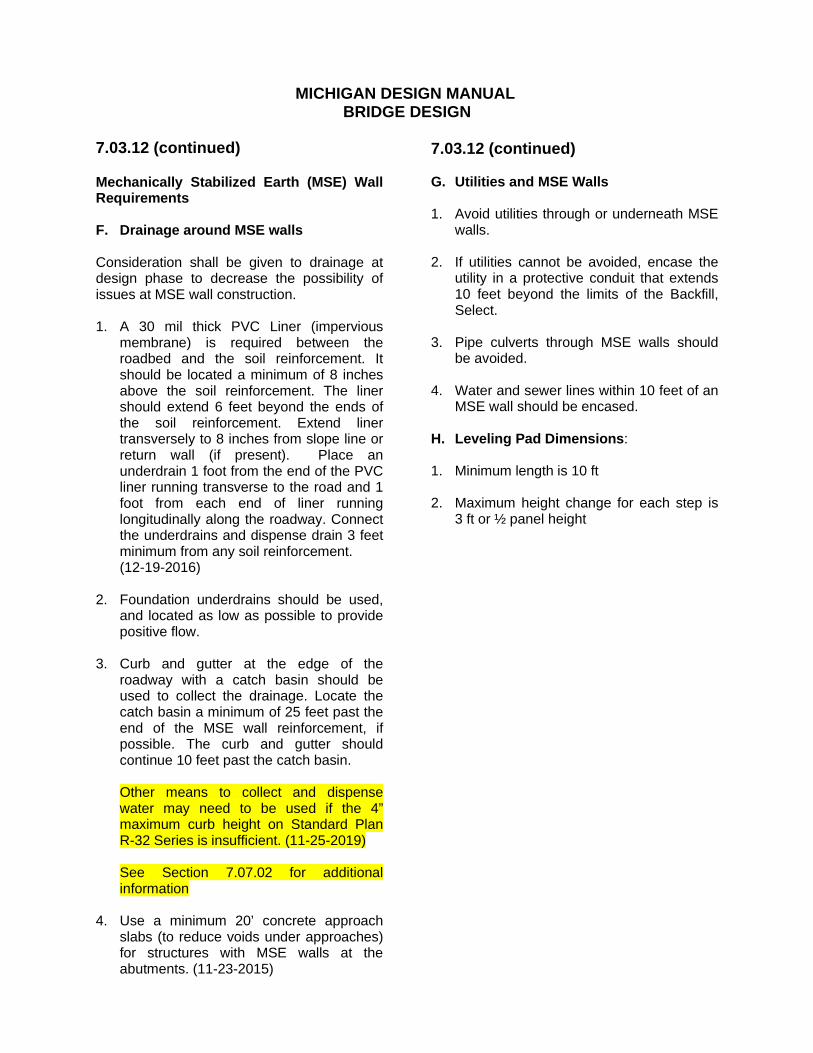
MICHIGAN DESIGN MANUAL BRIDGE DESIGN
7.03.12 (continued)
Mechanically Stabilized Earth (MSE) Wall Requirements
F. Drainage around MSE walls
Consideration shall be given to drainage at design phase to decrease the possibility of issues at MSE wall construction.
1. A 30 mil thick PVC Liner (impervious membrane) is required between the roadbed and the soil reinforcement. It should be located a minimum of 8 inches above the soil reinforcement. The liner should extend 6 feet beyond the ends of the soil reinforcement. Extend liner transversely to 8 inches from slope line or return wall (if present). Place an underdrain 1 foot from the end of the PVC liner running transverse to the road and 1 foot from each end of liner running longitudinally along the roadway. Connect the underdrains and dispense drain 3 feet minimum from any soil reinforcement. (12-19-2016)
2. Foundation underdrains should be used, and located as low as possible to provide positive flow.
3. Curb and gutter at the edge of the roadway with a catch basin should be used to collect the drainage. Locate the catch basin a minimum of 25 feet past the end of the MSE wall reinforcement, if possible. The curb and gutter should continue 10 feet past the catch basin.
Other means to collect and dispense water may need to be used if the 4” maximum curb height on Standard Plan R-32 Series is insufficient. (11-25-2019)
See Section 7.07.02 for additional information
4. Use a minimum 20’ concrete approach slabs (to reduce voids under approaches) for structures with MSE walls at the abutments. (11-23-2015)
7.03.12 (continued)
G. Utilities and MSE Walls
1. Avoid utilities through or underneath MSE walls.
2. If utilities cannot be avoided, encase the utility in a protective conduit that extends 10 feet beyond the limits of the Backfill, Select.
3. Pipe culverts through MSE walls should be avoided.
4. Water and sewer lines within 10 feet of an MSE wall should be encased.
H. Leveling Pad Dimensions:
1. Minimum length is 10 ft
2. Maximum height change for each step is 3 ft or ½ panel height

MICHIGAN DESIGN MANUAL BRIDGE DESIGN
7.07
APPROACH ITEMS
7.07.01
Guardrail
All new guardrail anchorages to bridges will utilize thrie beam guardrail according to Standard Plan R-67-Series and will be anchored directly to the bridge railing or pier filler walls. (5-6-99)
Where there are independent backwalls, that is, where there will be thermal deck movement at the abutments, the movement will be accommodated by the slots in the expansion section of the guardrail anchorage.
For additional information see Road Design Manual Section 7.01.16.
7.07.02
Curb and Gutter for Rural Bridges
The types and lengths of bridge approach curb and gutters (including valley gutter, where required) shall be determined by the bridge designer and shown on the General Plan of Structure Sheet.
A. Bridge approach curb and gutter will be according to Standard Plan R-32-Serieswith a 4” maximum curb height. It should be emphasized that this criteria is only a guide and that the designer should use engineering judgement in determining the type of structure to use.
1. Bridge Approach Curb and Gutter, Detail 5 will be used on the high end of a bridge where the bridge drains away from the curb and gutter or on departing end of bridges when guardrail is not needed.
2. Bridge Approach Curb and Gutter, Detail 6 and 6A will be used on the low ends of a bridge where the paved area draining to the curb and gutter is less than 2,500 SFT and the fill height is less than 10'-0". Where the drainage area exceeds 2,500 SFT, use Detail 7. (5-6-99)
7.07.02 (continued)
3. Bridge Approach Curb and Gutter, Detail 7 and 7A will be used on the low ends of a bridge where the fill height is over 10'-0". One downspout header shall be provided for each 3500 SFT of paved drainage area or fraction thereof. If it is not readily apparent whether to use Detail 6 or Detail 7, use Detail 7. (5-6-99)
If the bridge railing is other than the standard shape, the approach curb and gutter should be modified or transitioned to fit the bridge curb.
C. Payment for all types of bridge approach curb and gutter will be included in the pay item “Curb and Gutter, Bridge Approach”. The quantities shall be included in the Road Plans when bridge and road work is "packaged" together. (5-6-99)
For additional information see Road Design Manual Section 6.06.08 and MDOT Drainage Manual. (11-25-2019)
7.07.03 (5-6-99)
Bridge Approach Pavement
To eliminate approach pavement settlement, a concrete approach section will be used for all new bridges and bridge replacements, deck and superstructure replacement projects and concrete overlays. For hot mix asphalt (HMA) deck overlays, a concrete approach section is not necessary. The details of the approach slab shall be as specified on Standard Plan R-45-Series except on existing structures, where the grade will not be raised; the length of the approach slab shall match the existing slab joint. (9-2-2003)
Approach pavements for integral and semi-integral abutment designs shall be according to Bridge Design Guide 6.20.04 Series.
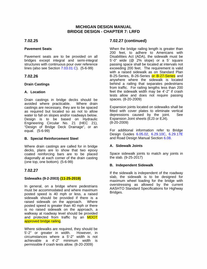
MICHIGAN DESIGN MANUAL BRIDGE DESIGN - CHAPTER 7: LRFD
7.02.25
Pavement Seats
Pavement seats are to be provided on all bridges except integral and semi-integral structures with continuous pour over reference lines (also see Section 7.03.01 C). (5-6-99)
7.02.26
Drain Castings
A. Location
Drain castings in bridge decks should be avoided where practicable. Where drain castings are necessary, they are to be spaced as required but located so as not to allow water to fall on slopes and/or roadways below. Design is to be based on Hydraulic Engineering Circular No. 21 (HEC 21), “Design of Bridge Deck Drainage”, or an equal. (5-6-99)
B. Special Reinforcement Steel
Where drain castings are called for in bridge decks, plans are to show that two epoxy coated reinforcing bars are to be placed diagonally at each corner of the drain casting (one top, one bottom). (5-6-99)
7.02.27
Sidewalks (9-2-2003) (11-25-2019)
In general, on a bridge where pedestrians must be accommodated and where maximum posted speed is 40 mph or less, a raised sidewalk should be provided if there is a raised sidewalk on the approach. Where posted speed is greater than 40 mph or there is no raised sidewalk on the approach, a walkway at roadway level should be provided and protected from traffic by an MDOT approved bridge railing.
Where sidewalks are required, they should be 5'-2" or greater in width. However, in circumstances where a 5'-2" width is not achievable a 4'-2" minimum width is permissible if crash tests allow. (8-20-2009)
7.02.27 (continued)
When the bridge railing length is greater than 200 feet, to adhere to Americans with Disabilities Act (ADA), the sidewalk must be 5’-0” wide (@ 2% slope) or a 5’ square passing space shall be located at intervals not exceeding 200 feet. The requirement is valid with a raised sidewalk as on Standard Plan B25Series, B26Series or B-27-Series and anywhere where the sidewalk is located behind a railing that separates pedestrians from traffic. For railing lengths less than 200 feet the sidewalk width may be 4’-2” if crash tests allow and does not require passing spaces. (8-20-2009)
Expansion joints located on sidewalks shall be fitted with cover plates to eliminate vertical depressions caused by the joint. See Expansion Joint sheets (EJ3 or EJ4). (8-20-2009)
For additional information refer to Bridge Design Guides 6.05.02, 6.29.10C, 6.29.17Eand Road Design Manual Section 6.08.
A. Sidewalk Joints
Space sidewalk joints to match any joints in the slab. (9-25-2017)
B. Independent Sidewalk
If the sidewalk is independent of the roadway slab, the sidewalk is to be designed for maximum wheel loading for the bridge with overstressing as allowed by the current AASHTO Standard Specifications for Highway Bridges.

MICHIGAN DESIGN MANUAL BRIDGE DESIGN - CHAPTER 7: LRFD
7.02.28
Railing (9-2-2003) (11-25-2019)
Where bridge railing is to be installed, and there are no sidewalks or the sidewalk is behind the railing, the railing shall be one of the bridge railing types currently approved for use by MDOT. The only types of railings currently used by MDOT are the Type 6 Barrier (see Standard Plan B-29-Series), Type 7 Barrier (see Standard Plan B-28-Series), the 2 Tube railing (see Standard Plan B21Series), 4 Tube railing (see Standard Plan B-26-series), Aesthetic Parapet Tube railing (see Standard Plan B-25-Series) and 3 Tube With Pickets (see Standard Plan B27Series).
Where bridge railing is to be installed on raised sidewalks it must be 4 Tube railing (see Standard Plan B-26-series) Aesthetic Parapet Tube railing (see Standard Plan B25Series) or 3 Tube With Pickets (see Standard Plan B27-Series).
A. Railing Types and Their Use (9-2-2003) (11-25-2019)
Generally, Bridge Barrier Railing, Type 6, is used on all new structures and reconstruction (major rehabilitation) bridge projects without sidewalks (see Standard Plan B-29-Series). On structures where sight distance or clear roadway width is a problem, Type 7 may be substituted (see Standard Plan B-28-Series). At stream crossings or scenic areas, Bridge Railing, 2 Tube, Aesthetic Parapet Tube, 4 Tube or 3 Tube With Pickets may be used (see Standard Plan B-21-Series, B-25-Series, B-26-Series or B-27-Series). On bridges where pedestrian or bicycle traffic is separated from vehicular traffic by a standard barrier, it is not necessary to provide a vehicular railing at the fascias. In such cases pedestrian fencing is desirable.
For structures without sidewalks, but where some pedestrian traffic is likely, a Bridge Railing, 4 Tube, Aesthetic Parapet Tube or 3 Tube With Pickets is to be used.
7.02.28 (continued)
B. Railing Finishes
A rubbed surface finish is required for concrete railings on all bridges with sidewalks and left turn bridges in urban areas.
Note 8.07.01E is to be included in the plans of all projects where a rubbed finish is required. It is to be placed on the same sheet and directly under the note making reference to the railing standard being used.
C. Joints
To avoid cracking, an open joint is required in concrete railings at all deck joints where reinforcing steel is not continued through the joint. False joints are not required in barrier railing.
A 1" joint shall be used in all concrete railings over the piers of continuous decks, at midspan on all structures with a span greater than 100'-0" and cantilever decks where the cantilever is more than 10'-0” long. The joint shall be perpendicular to the centerline even on skewed bridges. A 1" joint filler shall be used to fill the joint to ½” from the bevels of the railing. The remaining ½” shall be sealed with a polyurethane or polyurethane hybrid sealant. (5-1-2000) (2-21-2017)

MICHIGAN DESIGN MANUAL BRIDGE DESIGN - CHAPTER 7: LRFD
7.03.12 (continued)
Mechanically Stabilized Earth (MSE) Wall Requirements
F. Drainage around MSE walls
Consideration shall be given to drainage at design phase to decrease the possibility of issues at MSE wall construction.
1. A 30 mil thick PVC Liner (impervious membrane) is required between the roadbed and the soil reinforcement. It should be located a minimum of 8 inches above the soil reinforcement. The liner should extend 6 feet beyond the ends of the soil reinforcement. Extend liner transversely to 8 inches from slope line or return wall (if present). Place an underdrain 1 foot from the end of the PVC liner running transverse to the road and 1 foot from each end of liner running longitudinally along the roadway. Connect the underdrains and dispense drain 3 feet minimum from any soil reinforcement. (12-19-2016)
2. Foundation underdrains should be used, and located as low as possible to provide positive flow.
3. Curb and gutter at the edge of the roadway with a catch basin should be used to collect the drainage. Locate the catch basin a minimum of 25 feet past the end of the MSE wall reinforcement, if possible. The curb and gutter should continue 10 feet past the catch basin.
Other means to collect and dispense water may need to be used if the 4” maximum curb height on Standard Plan R-32 Series is insufficient. (11-25-2019)
See Section 7.07.02 for additional information
4. Use a minimum 20’ concrete approach slabs (to reduce voids under approaches) for structures with MSE walls at the abutments. This includes sliding slab approaches (Bridge Design Guide 6.20.03A). (11-23-2015)
7.03.12 (continued)
G. Utilities and MSE Walls
1. Avoid utilities through or underneath MSE walls.
2. If utilities cannot be avoided, encase the utility in a protective conduit that extends 10 feet beyond the limits of the Backfill, Select.
3. Pipe culverts through MSE walls should be avoided.
4. Water and sewer lines within 10 feet of an MSE wall should be encased.
H. Leveling Pad Dimensions:
1. Minimum length is 10 ft
2. Maximum height change for each step is 3 ft or ½ panel height

MICHIGAN DESIGN MANUAL BRIDGE DESIGN - CHAPTER 7: LRFD
7.07
APPROACH ITEMS
7.07.01
Guardrail
All new guardrail anchorages to bridges will utilize thrie beam guardrail according to Standard Plan R-67-Series and will be anchored directly to the bridge railing or pier filler walls. (5-6-99)
Where there are independent backwalls, that is, where there will be thermal deck movement at the abutments, the movement will be accommodated by the slots in the expansion section of the guardrail anchorage.
For additional information see Road Design Manual Section 7.01.16.
7.07.02
Curb and Gutter for Rural Bridges
The types and lengths of bridge approach curb and gutters (including valley gutter, where required) shall be determined by the bridge designer and shown on the General Plan of Structure Sheet.
A. Bridge approach curb and gutter will be according to Standard Plan R-32-Serieswith a 4” maximum curb height. It should be emphasized that this criteria is only a guide and that the designer should use engineering judgement in determining the type of structure to use.
1. Bridge Approach Curb and Gutter, Detail 5 will be used on the high end of a bridge where the bridge drains away from the curb and gutter or on departing end of bridges when guardrail is not needed.
2. Bridge Approach Curb and Gutter, Detail 6 and 6A will be used on the low ends of a bridge where the paved area draining to the curb and gutter is less than 2,500 SFT and the fill height is less than 10'-0". Where the drainage area exceeds 2,500 SFT, use Detail 7. (5-6-99)
7.07.02 (continued)
3. Bridge Approach Curb and Gutter, Detail 7 and 7A will be used on the low ends of a bridge where the fill height is over 10'-0". One downspout header shall be provided for each 3500 SFT of paved drainage area or fraction thereof. If it is not readily apparent whether to use Detail 6 or Detail 7, use Detail 7.
(5-6-99)
If the bridge railing is other than the standard shape, the approach curb and gutter should be modified or transitioned to fit the bridge curb.
B. Payment for all types of bridge approach curb and gutter will be included in the pay item “Curb and Gutter, Bridge Approach”. The quantities shall be included in the Road Plans when bridge and road work is "packaged" together. (5-6-99)
For additional information see Road Design Manual Section 6.06.08 and MDOT Drainage Manual. (11-25-2019)
7.07.03 (5-6-99)
Bridge Approach Pavement
To eliminate approach pavement settlement, a concrete approach section will be used for all new bridges and bridge replacements, deck and superstructure replacement projects and concrete overlays. For hot mix asphalt (HMA) deck overlays, a concrete approach section is not necessary. The details of the approach slab shall be as specified on Standard Plan R-45-Series except on existing structures, where the grade will not be raised; the length of the approach slab shall match the existing slab joint. (9-2-2003)
Approach pavements for integral and semi-integral abutment designs shall be according to Bridge Design Guide 6.20.04 Series.

MICHIGAN DESIGN MANUAL BRIDGE DESIGN
8.03 (continued)
GENERAL PLAN OF SITE SHEET
M. This bridge is part of an interchange and all area shown is within MDOT right-of-way.
N. Buildings marked thus have been removed.
O. Plan elevations refer to datum.
P. Topography shown here represents conditions existing at the time the field survey was made. However, these conditions (may) have been materially altered by the operations of others prior to this contract. [Use only when we have definite information that work has been done in the area.]
Q. The train movement and speed information shown in the proposal does not represent a commitment by the _____ railroad and is subject to change without notice.
R. Excavate crosshatched area to El . [Place this note in the vicinity to which it applies.]
S. Fill hatched area to El with material from channel excavation. [Place this note in the vicinity to which it applies.]
8.03 (continued)
T. Water level is subject to change. The contractor is responsible for making a determination of water levels that may exist during construction. [Use on all projects over water where the water level may impact the project work.]
U. ”Backfill, Structure, CIP”, _____ cubic yards. (12-5-2005)
V. Remove cubic yards of topsoil (and unsuitable material) and place cubic yards of “(Embankment, Structure,) (*Embankment,) CIP”. [*Use with pile supported footing.] (12-5-2005)
W. Soil classified as shall be undercut and replaced with “Embankment, Structure, CIP” compacted to 100 percent of maximum unit weight. Excavation and backfill quantities are based on an estimated undercut to elevation . Actual limits of excavation will be determined by the Engineer at the time of construction. (12-5-2005)
X. The following item(s) (is/are) railroad owned (fittings, ties, rails, etc.) and any of these items salvaged shall become the property of the railroad.
Y. Measures shall be taken to prevent debris from falling from the structure. (*If debris falls into the waterway, it shall be removed within 24 hours. Since disturbance of the waterway bottom may be as harmful as the debris itself, the preventive measures must be effective.) Removal of debris will not be paid for separately, but will be included in the bid item (“Structures, Rem”) (“Structures, Rem Portions”) (“Structures, Rehabilitation, Rem Portions”). [*Use for bridges over waterways.] (8-6-92)
(11-25-2019)
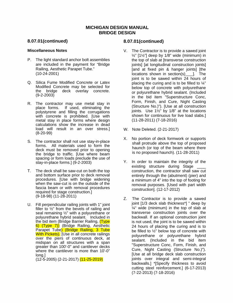
MICHIGAN DESIGN MANUAL BRIDGE DESIGN
8.07.01(continued)
Miscellaneous Notes
P. The light standard anchor bolt assemblies are included in the payment for “Bridge Railing, Aesthetic Parapet Tube.”
(10-24-2001)
Q. Silica Fume Modified Concrete or Latex Modified Concrete may be selected for the bridge deck overlay concrete. (922003)
R. The contractor may use metal stay in place forms. If used, eliminating the polystyrene and filling the corrugations with concrete is prohibited. [Use with metal stay in place forms where design calculations show the increase in dead load will result in an over stress.] (8-20-99)
S. The contractor shall not use stay-in-place forms. All materials used to form the deck must be removed prior to opening the bridge to traffic. [Use where beam spacing or form loads preclude the use of stay-in-place forms.] (9-2-2003)
T. The deck shall be saw-cut on both the top and bottom surface prior to deck removal procedures. [Use with bridge widening when the saw-cut is on the outside of the fascia beam or with removal procedures required for stage construction.]
(9-18-98) (11-28-2011)
U. Fill perpendicular railing joints with 1” joint filler to ½” from the bevels of railing and seal remaining ½” with a polyurethane or polyurethane hybrid sealant. Included in the bid item (Bridge Barrier Railing, (Type 6) (Type 7)) (Bridge Railing, Aesthetic Parapet Tube) (Bridge Railing, 3 Tube With Pickets). [Use in all concrete railings over the piers of continuous deck, at midspan on all structures with a span greater than 100'0" and cantilever decks where the cantilever is more than 10'-0” long.] (12-5-2005) (2-21-2017) (11-25-2019)
8.07.01(continued)
V. The Contractor is to provide a sawed joint ½” [1½”] deep by 1/8” wide (minimum) in the top of slab at [transverse construction joints] [at longitudinal construction joints] [and at fixed pin & hanger joints] [the locations shown in section(s) ]. The joint is to be sawed within 24 hours of placing the curing and is to be filled to ¼” below top of concrete with polyurethane or polyurethane hybrid sealant. (Included in the bid item "Superstructure Conc, Form, Finish, and Cure, Night Casting (Structure No.)"). [Use at all construction joints. Use 1½” by 1/8” at the locations shown for continuous for live load slabs.] (11-28-2011) (7-18-2016)
W. Note Deleted. (2-21-2017)
X. No portion of deck formwork or supports shall protrude above the top of proposed haunch (or top of the beam where there is no proposed haunch). (11-28-2011)
Y. In order to maintain the integrity of the existing structure during Stage ____ construction, the contractor shall saw cut entirely through the (abutment) (pier) and a minimum of 4” into the top of footing for removal purposes. [Used with part width construction]. (12-17-2012)
Z. The Contractor is to provide a sawed joint [1/3 deck slab thickness*] ” deep by ¼“ wide (minimum) in the top of slab at transverse construction joints over the backwall. If an optional construction joint is not used, the joint is to be sawed within 24 hours of placing the curing and is to be filled to ½” below top of concrete with polyurethane or polyurethane hybrid sealant. (Included in the bid item "Superstructure Conc, Form, Finish, and Cure, Night Casting (Structure No.)"). [Use at all bridge deck slab construction joints over integral and semi-integral backwalls.] *[Specify thickness to avoid cutting steel reinforcement.] (6-17-2013) (7-22-2013) (7-18-2016)

MICHIGAN DESIGN MANUAL BRIDGE DESIGN
8.09
REHABILITATION PROJECTS
8.09.01
Anchoring Bolts or Reinforcement in Existing Concrete
A. Mechanical expansion anchors shall be chosen from the Qualified Products List in the current MDOT Materials Source Guide. (12-5-2005)
B. Systems for anchoring horizontal or vertical (reinforcement) (bolts) in existing concrete shall be chosen from the Qualified Products List in the current MDOT Materials Source Guide. (12-5-2005)
C. All concrete anchors shall be installed according to manufacturer’s recommendations, except as modified in these plans. (5-1-2000)
D. Note deleted. (1-29-2018)
8.09.02
Bridge Deck Repair Notes
A. The work covered by these plans includes resurfacing the existing bridge deck and maintaining traffic.
B. The work covered by these plans includes replacing the existing curb or sidewalk with Bridge Barrier Railing, (Type 6) (Type 7) (Modified), resurfacing the existing bridge deck, and maintaining traffic. (11-25-2109)
C. The volume of “Concrete, (Bridge Deck Ovly) (Silica Fume Modified)” is based on the overlay and an estimated quantity to replace unsound concrete and to make (crown) (superelevation) (grade) adjustments as determined by the Engineer. (12-5-2005)
D. Note Deleted. (3-20-2017)
E. The plan quantity of scarifying involves an amount for the approaches which assumes an area equivalent to five passes over the entire surface, ¼” deep, to obtain a maximum depth of 1¼”. [Use where the deck will be hydrodemolished and the existing concrete approach slab will remain.] (9-18-98)
F. The contractor shall remove and replace only that portion of the (barrier) (sidewalk)(brush block) that is necessary for installation of the deck joint.
G. The bid item "Deck Joint, Rem" includes hand chipping within limits required for removal. (12-5-2005)
H. Before overlaying, sound concrete to determine whether the removal at either side of transverse joints will be adequate. Increase the removal limits as approved by the Engineer. (5-22-2017)

MICHIGAN DESIGN MANUAL BRIDGE DESIGN
8.09.03
Railing Replacement Notes
A. The work covered by these plans includes replacing the existing curb or sidewalk with Bridge Barrier Railing, (Type 6) (Type 7) (Modified) and maintaining traffic. (11-25-2109)
B. For molding, bevel, light standard anchor bolt assembly, and name plate details see Standard Plan B-103-Series.
C. For guardrail anchorage, bridge railing and name plate mounting details, see Standard Plan B- -Series.
(11-28-2011)
D. Removal of existing guardrail is included in the bid item “Guardrail, Type ”. [Applies to projects where the quantity is low or is not included in road plans.]
E. Measures shall be taken to prevent debris from falling from the structure. (*If debris falls into the waterway, it shall be removed within 24 hours. Since disturbance of the waterway bottom may be as harmful as the debris itself, the preventive measures must be effective.) Removal of debris will not be paid for separately but will be included in the bid item (“Structures, Rem”) (“Structures, Rem Portions”) (“Structures, Rehabilitation, Rem Portions”).[*Use for bridges over waterways.]
(8-6-1992) (11-25-2019)
F. The metal expansion joint shall not be coated except as follows, exposed metal surfaces at the concrete barrier shall be shop and field coated according to Subsections 716 & 715 of the Standard Specifications. (Included in the bid item “Bridge Joint, Revise Expansion Device”.) [Use when revising existing metal expansion joints.]
G. All steel for expansion joint shall be AASHTO M270, Grade 36. (9-18-1998)
8.09.03(continued)
Railing Replacement Notes
H. Remove rail and posts from parapet railing and retain anchor bolts. (Included in the bid item, “Bridge Railing, Thrie Beam Retrofit”.) [Use when circumstances such as sight distance or poor condition warrant rail and post removal.] (12-5-2005) (11-28-2011)
I. The work covered by these plans includes (removing) (retaining) the existing railing and constructing a new concrete block retrofit railing, B-50-Series, at the curb line atop the existing sidewalk or brush block. (11-25-2019)
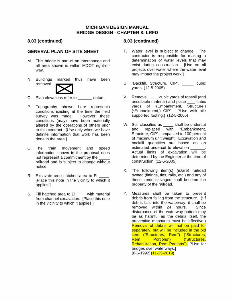
MICHIGAN DESIGN MANUAL BRIDGE DESIGN - CHAPTER 8: LRFD
8.03 (continued)
GENERAL PLAN OF SITE SHEET
M. This bridge is part of an interchange and all area shown is within MDOT right-of-way.
N. Buildings marked thus have been removed.
O. Plan elevations refer to datum.
P. Topography shown here represents conditions existing at the time the field survey was made. However, these conditions (may) have been materially altered by the operations of others prior to this contract. [Use only when we have definite information that work has been done in the area.]
Q. The train movement and speed information shown in the proposal does not represent a commitment by the _____ railroad and is subject to change without notice.
R. Excavate crosshatched area to El . [Place this note in the vicinity to which it applies.]
S. Fill hatched area to El with material from channel excavation. [Place this note in the vicinity to which it applies.]
8.03 (continued)
T. Water level is subject to change. The contractor is responsible for making a determination of water levels that may exist during construction. [Use on all projects over water where the water level may impact the project work.]
U. ”Backfill, Structure, CIP”, _____ cubic yards. (12-5-2005)
V. Remove cubic yards of topsoil (and unsuitable material) and place cubic yards of “(Embankment, Structure,) (*Embankment,) CIP”. [*Use with pile supported footing.] (12-5-2005)
W. Soil classified as shall be undercut and replaced with “Embankment, Structure, CIP” compacted to 100 percent of maximum unit weight. Excavation and backfill quantities are based on an estimated undercut to elevation . Actual limits of excavation will be determined by the Engineer at the time of construction. (12-5-2005)
X. The following item(s) (is/are) railroad owned (fittings, ties, rails, etc.) and any of these items salvaged shall become the property of the railroad.
Y. Measures shall be taken to prevent debris from falling from the structure. (*If debris falls into the waterway, it shall be removed within 24 hours. Since disturbance of the waterway bottom may be as harmful as the debris itself, the preventive measures must be effective.) Removal of debris will not be paid for separately, but will be included in the bid item (“Structures, Rem”) (“Structures, Rem Portions”) (“Structures, Rehabilitation, Rem Portions”). [*Use for bridges over waterways.]
(8-6-1992) (11-25-2019)

MICHIGAN DESIGN MANUAL BRIDGE DESIGN - CHAPTER 8: LRFD
8.07.01(continued)
Miscellaneous Notes
P. The light standard anchor bolt assemblies are included in the payment for “Bridge Railing, Aesthetic Parapet Tube.”
(10-24-2001)
Q. Silica Fume Modified Concrete or Latex Modified Concrete may be selected for the bridge deck overlay concrete. (922003)
R. The contractor may use metal stay in place forms. If used, eliminating the polystyrene and filling the corrugations with concrete is prohibited. [Use with metal stay in place forms where design calculations show the increase in dead load will result in an over stress.] (8-20-99)
S. The contractor shall not use stay-in-place forms. All materials used to form the deck must be removed prior to opening the bridge to traffic. [Use where beam spacing or form loads preclude the use of stay-in-place forms.] (9-2-2003)
T. The deck shall be saw-cut on both the top and bottom surface prior to deck removal procedures. [Use with bridge widening when the saw-cut is on the outside of the fascia beam or with removal procedures required for stage construction.]
(8-20-2009)
U. Fill perpendicular railing joints with 1” joint filler to ½” from the bevels of railing and seal remaining ½” with a polyurethane or polyurethane hybrid sealant. Included in the bid item (Bridge Barrier Railing, (Type 6) (Type 7)) (Bridge Railing, Aesthetic Parapet Tube) (Bridge Railing, 3 Tube With Pickets). [Use in all concrete railings over the piers of continuous deck, at midspan on all structures with a span greater than 100'0" and cantilever decks where the cantilever is more than 10'-0” long.] (12-5-2005) (2-21-2017) (11-25-2019)
8.07.01(continued)
V. The Contractor is to provide a sawed joint ½” [1½”] deep by 1/8” wide (minimum) in the top of slab at [transverse construction joints] [at longitudinal construction joints] [and at fixed pin & hanger joints] [the locations shown in section(s) ]. The joint is to be sawed within 24 hours of placing the curing and is to be filled to ¼” below top of concrete with polyurethane or polyurethane hybrid sealant. (Included in the bid item "Superstructure Conc, Form, Finish, and Cure, Night Casting (Structure No.)"). [Use at all construction joints. Use 1½” by 1/8” at the locations shown for continuous for live load slabs.] (11-28-2011) (7-18-2016)
W. Note Deleted. (2-21-2017)
X. No portion of deck formwork or supports shall protrude above the top of proposed haunch (or top of the beam where there is no proposed haunch). (8-20-2009)
Y. In order to maintain the integrity of the existing structure during Stage ____ construction, the contractor shall saw cut entirely through the (abutment) (pier) and a minimum of 4” into the top of footing for removal purposes. [Used with part width construction]. (12-17-2012)
Z. The Contractor is to provide a sawed joint [1/3 deck slab thickness*] ” deep by ¼“ wide (minimum) in the top of slab at transverse construction joints over the backwall. If an optional construction joint is not used, the joint is to be sawed within 24 hours of placing the curing and is to be filled to ½” below top of concrete with polyurethane or polyurethane hybrid sealant. (Included in the bid item "Superstructure Conc, Form, Finish, and Cure, Night Casting (Structure No.)"). [Use at all at bridge deck slab construction joints over integral and semi-integral backwalls.] *[Specify thickness to avoid cutting steel reinforcement.] (6-17-2013) (7-22-2013) (7-18-2016)

MICHIGAN DESIGN MANUAL BRIDGE DESIGN - CHAPTER 8: LRFD
8.09
REHABILITATION PROJECTS
8.09.01
Anchoring Bolts or Reinforcement in Existing Concrete
A. Mechanical expansion anchors shall be chosen from the Qualified Products List in the current MDOT Materials Source Guide. (12-5-2005)
B. Systems for anchoring horizontal or vertical (reinforcement) (bolts) in existing concrete shall be chosen from the Qualified Products List in the current MDOT Materials Source Guide. (12-5-2005)
C. All concrete anchors shall be installed according to manufacturer’s recommendations, except as modified in these plans. (5-1-2000)
D. Note deleted. (1-29-2018)
8.09.02
Bridge Deck Repair Notes
A. The work covered by these plans includes resurfacing the existing bridge deck and maintaining traffic.
B. The work covered by these plans includes replacing the existing curb or sidewalk with Bridge Barrier Railing, (Type 6) (Type 7) (Modified), resurfacing the existing bridge deck, and maintaining traffic. (11-25-2019)
C. The volume of “Concrete, (Bridge Deck Ovly) (Silica Fume Modified)” is based on the overlay and an estimated quantity to replace unsound concrete and to make (crown) (superelevation) (grade) adjustments as determined by the Engineer. (12-5-2005)
D. Note Deleted. (3-20-2017)
E. The plan quantity of scarifying involves an amount for the approaches which assumes an area equivalent to five passes over the entire surface, ¼” deep, to obtain a maximum depth of 1¼”. [Use where the deck will be hydrodemolished and the existing concrete approach slab will remain.] (9-18-98)
F. The contractor shall remove and replace only that portion of the (barrier) (sidewalk)(brush block) that is necessary for installation of the deck joint.
G. The bid item "Deck Joint, Rem" includes hand chipping within limits required for removal. (12-5-2005)
H. Before overlaying, sound concrete to determine whether the removal at either side of transverse joints will be adequate. Increase the removal limits as approved by the Engineer. (5-22-2017)
MICHIGAN DESIGN MANUAL BRIDGE DESIGN - CHAPTER 8: LRFD
8.09.03
Railing Replacement Notes
A. The work covered by these plans includes replacing the existing curb or sidewalk with Bridge Barrier Railing, (Type 6) (Type 7) (Modified) and maintaining traffic. (11-25-2019)
B. For molding, bevel, light standard anchor bolt assembly, and name plate details see Standard Plan B-103-Series.
C. For guardrail anchorage, bridge railing and name plate mounting details, see Standard Plan B- -Series. (8-20-2009)
D. Removal of existing guardrail is included in the bid item “Guardrail, Type ”. [Applies to projects where the quantity is low or is not included in road plans.]
E. Measures shall be taken to prevent debris from falling from the structure. (*If debris falls into the waterway, it shall be removed within 24 hours. Since disturbance of the waterway bottom may be as harmful as the debris itself, the preventive measures must be effective.) Removal of debris will not be paid for separately but will be included in the bid item (“Structures, Rem”) (“Structures, Rem Portions”) (“Structures, Rehabilitation, Rem Portions”). [*Use for bridges over waterways.]
(8-6-1992) (11-25-2019)
F. The metal expansion joint shall not be coated except as follows, exposed metal surfaces at the concrete barrier shall be shop and field coated according to Subsections 716 & 715 of the Standard Specifications. (Included in the bid item “Bridge Joint, Revise Expansion Device”.) [Use when revising existing metal expansion joints.]
G. All steel for expansion joint shall be AASHTO M270, Grade 36. (9-18-1998)
8.09.03(continued)
Railing Replacement Notes
H. Remove rail and posts from parapet railing and retain anchor bolts. (Included in the bid item, “Bridge Railing, Thrie Beam Retrofit”.) [Use when circumstances such as sight distance or poor condition warrant rail and post removal.] (8-20-2009)
I. The work covered by these plans includes (removing) (retaining) the existing railing and constructing a new concrete block retrofit railing, B-50-Series, at the curb line atop the existing sidewalk or brush block. (11-25-2019)

MICHIGAN DESIGN MANUAL BRIDGE DESIGN
12.05
RAILING UPGRADING (11-25-2019)
Bridge railings shall be upgraded where the existing facility is found to be inadequate, either because of crash experience or because it is not a current MDOT approved railing. Upgrading will be scheduled according to the following guidelines:
A. Railings shall be upgraded at any location where a revised railing can be expected to reduce the severity of crashes.
B. Railings shall be upgraded at any location within safety upgrading projects.
C. Railings shall be upgraded when bridge reconstruction of any nature is planned.
D. Railings shall be upgraded where pedestrian screening is added to a bridge.
The decision to retain, retrofit, or replace existing railing depends on the type and condition of the railing and the curb or sidewalk treatment.
Where replacement is required, the proposed railing must be a current MDOT approved railing. (5-1-2000)
12.05.01
Approved MDOT Railings(5-1-2000) (11-25-2019)
Current MDOT approved railings are:
A. Bridge Barrier Railing, Type 6 (B-29-Series)
B. Bridge Barrier Railing, Type 7 (B-28-Series)
C. Bridge Railing, Aesthetic Parapet Tube (B-25-Series)
D. Bridge Railing, 2 Tube (B-21-Series)
E. Bridge Railing, Thrie Beam Retrofit (B-22&23-Series)
F. Bridge Railing, 4 Tube (9-2-2003) (B-26-Series)
G. Bridge Railing, 3 Tube With Pickets (B-27-Series)
H. Bridge Railing, Concrete Block Retrofit (B-50-Series)
I. Bridge Barrier Railing, Type 6, Modified * (B-29-Series & Bridge Design Guides) J. Bridge Barrier Railing, Type 7, Modified * (B-28-Series & Bridge Design Guides)
* Type 6 & Type 7 modified (adhesive anchored) railings must only be used for non-NHS routes.

MICHIGAN DESIGN MANUAL BRIDGE DESIGN
12.05.02
Existing Railings and Upgrading Options (11-25-2019)
Use the following table to determine railing treatment on projects. Table options are minimum railing upgrading criteria and when circumstances warrant the railing shall be replaced rather than retrofitted or retained.
Option Offset Posted
Speed
R4 Railing
(concrete
posts)
R5 Railing
(metal
posts)
Concrete
Parapet
Railing
Aluminum
Railings
(2&3 Tube)
R15 Railing
(GM Shape),
Type 4 & 5
Reconstruction All All Replace Replace
Reh
ab
ilit
ati
on
( 6 )
Gaurdrail Retrofit
Sidewalk/ Brushblock ≤ 2’-6” ( 1 )
All Retrofit
(Std B-22) Replace Retrofit ( 2 )
(Std B-23) Replace
Replace or Retain ( 4 )
Sidewalk/ Brushblock > 2’-6” ( 1 )
≤ 40 mph Replace or Guardrail (3) Retain
> 40 mph Replace
Concrete Block Retrofit, B-50( 5 )
Sidewalk/ Brushblock ≤ 1’-6” ( 1 )
All Remove Railing and Retrofit
Sidewalk/ Brushblock ≥ 1’-6” ( 1 )
All Remove or Retain Railing and Retrofit
Type 6 or 7, Modified
(non-NHS only)All All Remove Railing and Replace( 6 )
Preventive Maintenance
All All Retain Retain
Replace = Replace railing with Standard MDOT approved bridge rail. Retrofit = Retrofit per Standard Plans B22, B-23 or B-50 Series. Retain = Retain existing bridge rail. Guardrail = Attach thrie beam guardrail directly to concrete posts.
1 Where sidewalks are required for pedestrian use, they shall provide at least 4’-0” clear distance between the bevel point and the retained, retrofitted or replaced railing. (12-5-2005).
2 Normally, handrails should not be removed; however, if they are removed, anchor bolts should be left in place. This treatment is accepted as crash tested for Michigan Thrie Beam Retrofit (Std B-23).
3 Replace railing if circumstances warrant, otherwise attach thrie beam guardrail to railing (concrete posts) with ⅞” diameter bolts. Wood blocks and blockouts shall not be used in guardrail attachment to posts. If approach guardrail is present or being installed, it shall be attached to thrie beam guardrail on bridge; use thrie beam transition and expansion sections as required. If no approach guardrail is present or being installed terminate thrie beam guardrail at end post of railing with thrie beam terminal connector.
4 Obsolete Standards R15 A - R15 N, X-17 and B-17 Series & X-20 and B-20 Series. Replace if warranted by the condition of the existing barrier and the crash history, retain otherwise.
5 Sidewalk/brushblock height at curb must be ≥ 10”.
6 Remove sidewalk width as needed for shoulder width.

MICHIGAN DESIGN MANUAL BRIDGE DESIGN
12.05.02 (continued)
Existing Railings and Upgrading Options
While a thrie beam retrofit, concrete block retrofit or Type 6 or 7, Modified is an acceptable means of upgrading existing substandard railings, there will be locations where shoulder widths will be less than the minimums recommended for minor bridge deck rehabilitation. In these situations, the project manager shall request a design exception or design variance for shoulder widths. (8-6-92) (11-25-2019)
12.05.03
Horizontal Curvature
Where a structure is on a horizontal curve with a radius less than or equal to 950 feet, consideration should be given for a special railing system to accommodate sight distance. This may require the complete removal and replacement of the existing railing system.
12.05.04
Revisions to Guardrails
When a bridge railing is replaced with a new railing, approach and trailing guardrails shall be changed to meet current standards. Guardrail having corrosion resistant (rusty steel) beam elements shall be replaced. Where obsolete guardrail extends a considerable distance from the structure, guardrail replacement should be limited to 200'-0" in each quadrant. See Road Design Manual Section 7.01.44 for guardrail upgrading on local roads. (8-6-92) (3-26-2012) (6-25-2018)