road & bridge design publications - michigan
TRANSCRIPT

Road & Bridge Design Publications
Monthly Update – August 2012
1
Revisions for the month of August are listed and displayed below. New special details are to be included in projects submitted for the November letting as is stated on the special detail index sheets. Please contact Wayne Pikka ([email protected]) for any questions related to the road changes or Vladimir Zokvic ([email protected]) for questions related to the bridge changes. Special Details R-100-G: Seeding and Tree Planting: On sheet one, in regards to the note on the use of mulch blanket in areas of superelevation, a sentence was added which directs the use of high velocity much blanket on the low side of curve when the rate of superelevation is greater than 5%. Road Design Manual 6.04.05: Ride Quality: Effective with the January 2013 letting, projects that include the ride quality specifications will require location specific classifications that identify applicable roughness index, method of measurement, incentives, corrective actions and exclusions. This revision includes instructions to the designer for the assignment and listing of ride quality classifications. An accompanying Frequently Used Special Provision is currently pending approval and will be posted soon. Questions regarding ride quality classification can be directed to Mr. Tom Hynes of the Construction Field Services Division at (517) 322-5711 or Email [email protected]. 9.02.04B: Including Utility Work in Contracts: This section was revised to clarify that utility work included in MDOT contracts is covered by a special provision while utility coordination information is included by a notice to bidders. The sample SP was replaced by an example that does not combine the coordination component with the work component. 12.10.08: PITWS General Information: Minor changes were made to improve the operation and measuring accuracy of the PITWS. 14.54: OEC Meeting: This section was updated to current practice.

Road & Bridge Design Publications
Monthly Update – August 2012
2
Bridge Design Manual 7.03.04, 7.03.08 D.1, 7.03.09 A.2 (LFD only), 7.03.09 A.3, 7.03.09 A.4(LRFD only), 7.03.09 B, 7.06.04 B.1, 7.06.04 C.9.b, 7.06.04 C.10.b: Construction and Technology changed to Construction Field Services. 7.02.05 C (LRFD only), 7.06.04 C.14.a, 7.06.04 G.3.a: Construction and Technology changed to Operations Field Services. 7.02.19 (LRFD & LFD): Added reference for Ride Quality. 7.02.32 (LRFD & LFD): New Section added for Ride Quality. For a more detailed description, see RDM section 6.04.05 above. 7.03.09 B.1.b (LRFD): Updated metal shell 12” O.D. pile to 0.312” wall thickness. 7.03.09 A.9 (LFD): The minimum cast-in-place concrete pile shell thickness shall be 0.312” for Load Factor Design. 8.06.05 B (LRFD): Deleted 0.250" nominal thickness pile shell. 8.06.05 B (LFD): All pile shells shall now have minimum 0.312” thickness for Load Factor Design. Updates to MDOT Cell Library, Bridge Auto Draw Program, etc., may be required in tandem with some of this month's updates. Until such updates to automated tools can be made, it is the designer's/detailer's responsibility to manually incorporate any necessary revisions to notes and plan details to reflect these revisions.

Index to Special Details
8-20-2012
SPECIAL DETAIL
NUMBER
NUMBER
OF SHEETS
TITLE
CURRENT
DATE
21
2 GUARDRAIL AT INTERSECTIONS 5-24-01
24
5
GUARDRAIL ANCHORED IN BACK SLOPE TYPES 4B & 4T 7-22-02
R-29-H
4
DRIVEWAY OPENINGS & APPROACHES, AND CONCRETE SIDEWALK 10-20-11
R-31-F
2
INTEGRAL CURB AND INTEGRAL CURB & GUTTER 1-30-12
R-41-G
2
LONGITUDINAL PAVEMENT JOINTS 4-9-12
R-42-F
6
TYPICAL JOINT LAYOUTS FOR CONCRETE PAVEMENT 12-6-10
R-43-I
2
LOCATION OF TRANSVERSE JOINTS IN PLAIN CONCRETE PAVEMENT 2-8-12
R-45-I
2 PAVEMENT REINFORCEMENT FOR BRIDGE APPROACH 12-6-11
R-54-H
4 CONCRETE BARRIER, SINGLE FACE 5-18-12
R-80-E
8
GRANULAR BLANKETS, UNDERDRAINS, OUTLET ENDINGS & BULKHEADS 6-13-12
R-99-B
2
CHAIN LINK FENCE WITH WIRE ROPE 11-1-00
*R-100-G
4
SEEDING AND TREE PLANTING 8-13-12
R-126-I 5
PLACEMENT OF TEMPORARY BARRIER 3-26-12
* Denotes New or Revised Special Detail to be included in projects for (beginning with) the November letting.
Note: Former Standard Plans IV-87, IV-89, IV-90, and IV-91 Series, used for building cast-in-place concrete head walls for elliptical and circular pipe culverts, are now being replaced with plans that detail each specific size. The Municipal Utilities Unit will provide these full sized special details for inclusion in construction plans for MDOT jobs. To assure prompt delivery, requests must be made in advance.
Former Standard Plans IV-93 and IV-94 series have been replaced with precast concrete box & three-sided culverts as per the 2012 Standard Specifications for Construction.

Index to Bridge Detail Sheets
8-20-2012
DETAIL NUMBER
NUMBER
OF SHEETS
TITLE
CURRENT
DATE
B-21-I 4 BRIDGE RAILING, 2 TUBE 6-3-11
B-23-E 4 BRIDGE RAILING, THRIE BEAM RETROFIT 10-19-09
B-25-G 6 BRIDGE RAILING, AESTHETIC PARAPET TUBE 7-10-12
EJ3Z
1 or 2 EXPANSION JOINT DETAILS 6-8-11
EJ4M
1 or 2
EXPANSION JOINT DETAILS 6-8-11
PC-2G
1
70" PRESTRESSED CONCRETE I-BEAM DETAILS 3-31-06
PC-4E
1
PRESTRESSED CONCRETE 1800 BEAM DETAILS 3-31-06
PC-1L
1
PRESTRESSED CONCRETE I-BEAM DETAILS 7-12-06
* Denotes New or Revised Special Detail to be included in projects for
(beginning with) the November letting. Note: Details EJ3Z & EJ4M are interactive, i.e. designers and detailers choose details based
upon railing type and angle of crossing. Place all details appropriate for the project, structure specific information, and the Expansion Joint Device quantity on the sheet. The sheet shall then be added to the plans as a normal plan sheet.
Detail PC-1L, PC-2G and PC-4E shall have structure specific information and quantities added to the sheet. The sheet shall then be added to the plans as a normal plan sheet.

PAVEMENT
4% 4%
SEED, FERTILIZE, AND MULCH AS SPECIFIED ON PLANS
TYPICAL SLOPE AND DITCH PROTECTION
MULCH BLANKET SPILLWAY DITCH
PAVEMENT
18’ MIN. HIGH VELOCITY MULCH BLANKET
MEDIAN DITCH
R-100-G1
PAVED SHOULDER
AGGREGATE
PAVEMENT
BACKSLOPE
(SEE NOTES)
DITCH
SEE DETAIL A
AS SPECIFIED ON PLANS
AND MULCH
SEED, FERTILIZE,
PAVED SHOULDER
AGGREGATE
PAVEMENT
GROUND
UNDISTURBED
SEE DETAIL A
6" TO 10"
OR EARTH
AGGREGATE
3" TO 4"
B.L.T.
W.K.P. 4
DETAIL A
SEE DETAIL A
ABOVE DITCH BOTTOM
VERTICAL HEIGHT OF 1’-0"
AS SPECIFIED ON PLANS TO
HIGH VELOCITY MULCH BLANKET
SEE DETAIL ASEE DETAIL A
ON GUARDRAIL FILL SLOPE
MULCH BLANKET
MULCH BLANKET
ANCHOR
AND TREE PLANTING
SEEDING
USE STANDARD MULCH BLANKET ON FILL SLOPES FLATTER THAN 1:2
USE HIGH VELOCITY MULCH BLANKET ON FILL SLOPES 1:2 OR STEEPER
SHOULDER
PAVED
SHOULDER
AGGREGATE
SHOULDER
PAVED
SHOULDER
AGGREGATE
MULCH BLANKET
* 6’ - 8’
MULCH BLANKET
* 6’ - 8’
MULCH BLANKET
* 6’ - 8’
USE 6’ WIDE MULCH BLANKET IN ALL OTHER APPLICATIONS.
AND OTHER UNIQUE SITUATIONS AS DETERMINED BY THE ENGINEER.
USE 8’ WIDE MULCH BLANKET IN SANDY SOILS, WHEN SHOULDERS ARE 4’ WIDE OR LESS
PAVEMENTS HAVING A RATE OF SUPERELEVATION GREATER THAN 5%.
5% OR LESS. HIGH VELOCITY MULCH BLANKET SHALL BE USED ON THE LOW SIDE OF
SUPERELEVATED SECTIONS, AND LOW SIDES OF PAVEMENTS HAVING A SUPERELEVATION OF
MULCH BLANKET SHALL BE USED ON BOTH SIDES OF NORMAL SECTIONS, HIGH SIDES OF ALL
* NOTE:
DEPARTMENT DIRECTOR MICHIGAN DEPARTMENT OF TRANSPORTATION
OF
SHEET
PLAN DATEF.H.W.A. APPROVALCHECKED BY:
DRAWN BY:
Michigan Department of Transportation
BUREAU OF HIGHWAY DEVELOPMENT STANDARD PLAN FOR
APPROVED BY:
APPROVED BY:
Kirk T. Steudle
BY
PREPARED
DESIGN DIVISION
DIRECTOR, BUREAU OF FIELD SERVICES
DIRECTOR, BUREAU OF HIGHWAY DEVELOPMENT
8-13-2012
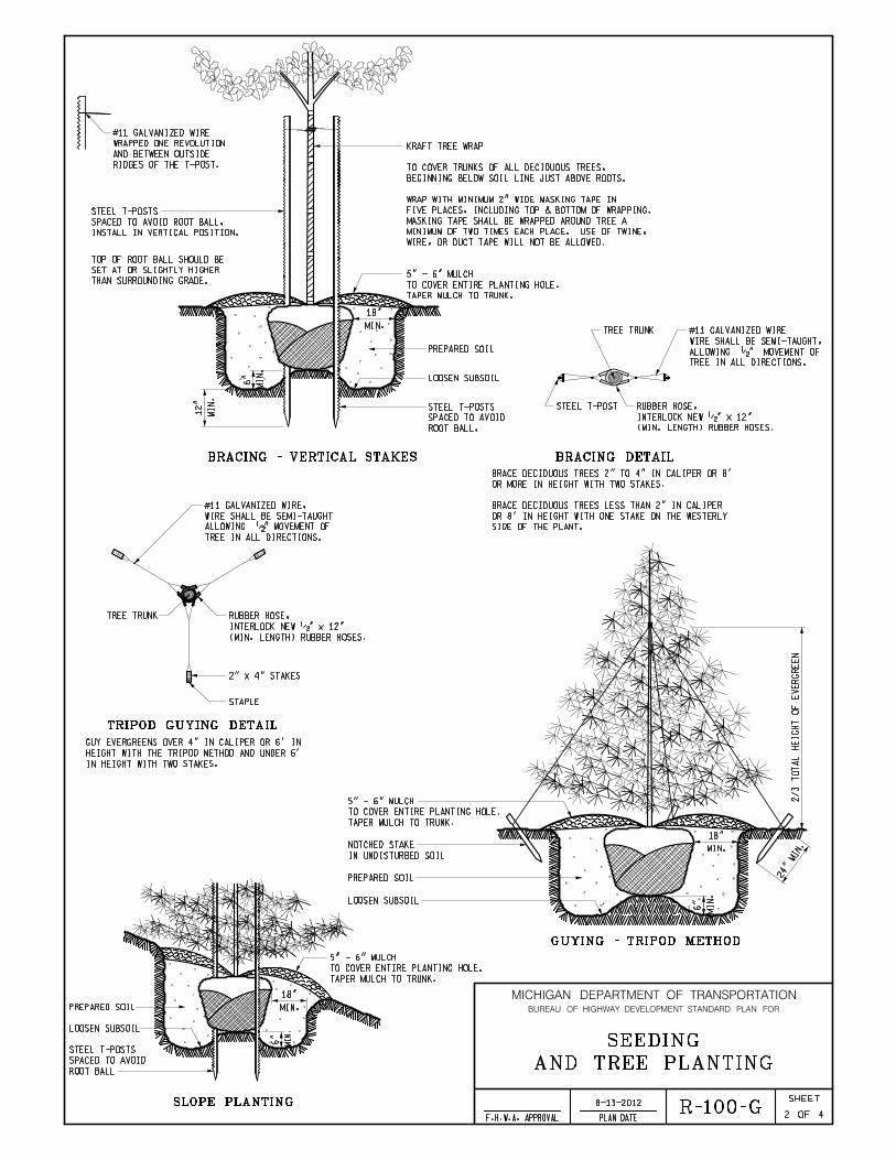
BRACING DETAILBRACING - VERTICAL STAKES
TRIPOD GUYING DETAIL
2
LOOSEN SUBSOIL
PREPARED SOIL
TREE TRUNK
STEEL T-POST
ROOT BALL.
SPACED TO AVOID
STEEL T-POSTS
18"
MIN.
MI
N.
6"
MI
N.
12"
TAPER MULCH TO TRUNK.
TO COVER ENTIRE PLANTING HOLE.
5" - 6" MULCH
TREE TRUNK
2" x 4" STAKES
STAPLE
2/3
TO
TA
L
HEI
GH
T
OF
EV
ER
GR
EE
N
24"
MIN.
18"
MIN.
MI
N.
6"
PREPARED SOIL
LOOSEN SUBSOIL
IN UNDISTURBED SOIL
NOTCHED STAKE
TAPER MULCH TO TRUNK.
TO COVER ENTIRE PLANTING HOLE.
5" - 6" MULCH
4
AND TREE PLANTING
SEEDING
TAPER MULCH TO TRUNK.
TO COVER ENTIRE PLANTING HOLE.
5" - 6" MULCH
(MIN. LENGTH) RUBBER HOSES.
INTERLOCK NEW �" x 12"
RUBBER HOSE,
TREE IN ALL DIRECTIONS.
ALLOWING �" MOVEMENT OF
WIRE SHALL BE SEMI-TAUGHT,
#11 GALVANIZED WIRE
WIRE, OR DUCT TAPE WILL NOT BE ALLOWED.
MINIMUM OF TWO TIMES EACH PLACE. USE OF TWINE,
MASKING TAPE SHALL BE WRAPPED AROUND TREE A
FIVE PLACES, INCLUDING TOP & BOTTOM OF WRAPPING.
WRAP WITH MINIMUM 2" WIDE MASKING TAPE IN
BEGINNING BELOW SOIL LINE JUST ABOVE ROOTS.
TO COVER TRUNKS OF ALL DECIDUOUS TREES,
KRAFT TREE WRAP
RIDGES OF THE T-POST.
AND BETWEEN OUTSIDE
WRAPPED ONE REVOLUTION
#11 GALVANIZED WIRE
THAN SURROUNDING GRADE.
SET AT OR SLIGHTLY HIGHER
TOP OF ROOT BALL SHOULD BE
SIDE OF THE PLANT.
OR 8’ IN HEIGHT WITH ONE STAKE ON THE WESTERLY
BRACE DECIDUOUS TREES LESS THAN 2" IN CALIPER
OR MORE IN HEIGHT WITH TWO STAKES.
BRACE DECIDUOUS TREES 2" TO 4" IN CALIPER OR 8’
GUYING - TRIPOD METHOD
SLOPE PLANTING
ROOT BALL
SPACED TO AVOID
STEEL T-POSTS
LOOSEN SUBSOIL
PREPARED SOIL MIN.
18"
MI
N.
6"
IN HEIGHT WITH TWO STAKES.
HEIGHT WITH THE TRIPOD METHOD AND UNDER 6’
GUY EVERGREENS OVER 4" IN CALIPER OR 6’ IN
TREE IN ALL DIRECTIONS.
ALLOWING �" MOVEMENT OF
WIRE SHALL BE SEMI-TAUGHT
#11 GALVANIZED WIRE,
(MIN. LENGTH) RUBBER HOSES.
INTERLOCK NEW �" x 12"
RUBBER HOSE,
INSTALL IN VERTICAL POSITION.
SPACED TO AVOID ROOT BALL,
STEEL T-POSTS
R-100-G
MICHIGAN DEPARTMENT OF TRANSPORTATION
OF
SHEET
PLAN DATEF.H.W.A. APPROVAL
BUREAU OF HIGHWAY DEVELOPMENT STANDARD PLAN FOR
8-13-2012

MICHIGAN DEPARTMENT OF TRANSPORTATION
OF
SHEET
PLAN DATEF.H.W.A. APPROVAL
BUREAU OF HIGHWAY DEVELOPMENT STANDARD PLAN FOR
PACK FIRMLY, AND PUDDLE WITH WATER.
FILL PREPARED SOIL TO � THE DEPTH OF THE ROOT BALL,
FLUSH WITH SURROUNDING GROUND LEVEL.
BACKFILL WITH PREPARED SOIL WHICH, AFTER COMPACTION, IS
OF PLANT POCKET TO BREAK ANY GLAZING CAUSED BY DIGGING.
LOOSEN SUBSOIL TO A DEPTH OF 4". LOOSEN EARTH ON SIDES
PLANTING NOTES:
WRAP, AND BRACE AND GUY.
COVER ENTIRE PLANT POCKET AREA WITH 5"-6" MULCH. PRUNE,
IMMEDIATELY.
ALL EXCAVATED MATERIAL SHALL BE REMOVED FROM THE SITE -
SHALL BE COMPLETELY REMOVED AT THE TIME OF PLANTING.
WHEN PLANTS ARE FURNISHED IN CONTAINERS, CONTAINERS
DEPTHS ARE SHOWN AFTER SETTLING.
TREE HEIGHTS ARE SHOWN BEFORE PRUNING. TREE PLANTING
INACCESSIBLE TO VEHICLES.
RESPECTIVELY OF THE NEAREST EDGE OF METAL - EXCEPT WHERE
TREES AND SHRUBS SHALL NOT BE PLANTED WITHIN 50’ AND 30’
ROOT BALL
SPACED TO AVOID
STEEL T-POSTS
LOOSEN SUBSOIL
PREPARED SOIL
6"
MI
N.
MIN.
18"
TAPER MULCH TO TRUNK.
TO COVER ENTIRE PLANTING HOLE.
5" - 6" MULCH
BRACING - SEE DETAIL
MULTIPLE STEM TREES
AS PER PLANS
TAPER MULCH TO TRUNK.
TO COVER ENTIRE PLANTING HOLE.
5" - 6" MULCH
1 ON 2 SLOPE, TYP.
PREPARED SOIL
RAISED SHRUB BED DETAIL
PREPARED SOIL
12"
MI
N.
MI
N.
3"
FIRST AND SECOND WATERING AND CULTIVATION SHALL INCLUDE SHRUB BEDS.
SHRUB BEDS PRIOR TO PLANTING AND BARK PLACEMENT.
ON THE PLANS. SPRAY A NON-PERSISTANT GLYPHOSATE HERBICIDE TO ENTIRE
CUT 6" X 12" (MIN.) EDGING AROUND THE PERIMETER OF ALL SHRUB BEDS SHOWN
SHRUB BEDS ARE TO BE PAID FOR BY THE PAY ITEM ’SITE PREPARATION’.
THE MAIN VIEWING DIRECTION.
ALL PLANTS SHALL BE SET PLUMB AND HAVE THE BEST SIDE OF PLANT FACING
6"
MIN
SHRUB BED DETAIL
6"
MIN
6"
MIN
LOOSEN SUBSOIL
6"
MI
N
6"
MI
N
6"
MI
N
MIN
12"
SHRUB BED EDGING DETAIL
MIN
6"
3 4
AND TREE PLANTING
SEEDING
TAPER MULCH TO TRUNK.
COVER ENTIRE PLANT BED.
5" - 6" MULCH
R-100-G8-13-2012

MICHIGAN DEPARTMENT OF TRANSPORTATION
OF
SHEET
PLAN DATEF.H.W.A. APPROVAL
BUREAU OF HIGHWAY DEVELOPMENT STANDARD PLAN FOR
4 4
R-96-SERIES.
CONSTRUCTION AS AN EROSION CONTROL MEASURE. SEE STANDARD PLAN
ITEMS CALLED FOR ON THIS STANDARD MAY ALSO BE USED DURING
CONTROL.
ALL DITCHES SHOULD HAVE HIGH VELOCITY MULCH BLANKET FOR EROSION
ADHESIVE OR WITH A MULCH NET.
MULCH BLANKET OR STANDARD MULCH ANCHORED IN PLACE WITH A MULCH
THE REMAINING AREAS WILL BE SEEDED, FERTILIZED, AND MULCHED WITH
WILL BE SEEDED, FERTILIZED, AND MULCHED WITH MULCH BLANKET.
THE FIRST 6’ BEHIND THE CURB OR SHOULDER IN URBAN MEDIAN AREAS
ANCHORING MULCH IS REQUIRED WHERE MULCH BLANKET IS INSTALLED.
FERTILIZED, AND TOPSOILED AS SPECIFIED ON PLANS. NO MULCH OR
ALL AREAS WHERE MULCH BLANKET IS CALLED FOR SHALL BE SEEDED,
AND TREE PLANTING
SEEDING
SLOPE.
BACKSLOPE RESTORATION TREATMENT SHALL BE THE SAME AS THE FRONT
PLANS AND CURRENT SPECIFICATIONS.
WHICH INCLUDES SEEDING WITH MULCHING, WILL BE ACCORDING TO THE
DESIGN AND MATERIALS USED TO CONSTRUCT THE COMPLETE SECTION,
AS THESE ITEMS RELATE TO ROADWAY CONSTRUCTION. THE ACTUAL
THIS STANDARD ILLUSTRATES THE TYPICAL USE OF SEEDING WITH MULCH,
SEEDING NOTES:
PERENNIAL BEDS ARE TO BE PAID FOR BY THE PAY ITEM ’SITE PREPARATION’.
COVER ENTIRE PLANT POCKET AREA WITH 5" - 6" MULCH AS SHOWN.
FOR SHIPPING, STORAGE AND HANDLING REQUIREMENTS.
REFER TO THE "SPECIAL PROVISIONS FOR BARE ROOT PLANTING"
PRIOR TO PLANTING.
MAINTAIN ROOT MOISTURE BY KEEPING ROOTS IMMERSED IN WATER
SPECIALIST.
ROOTS, AND AS REQUIRED BY THE DISTRICT FORESTER OR RESOURCE
ROOT PRUNE AS NECESSARY TO REMOVE ALL DAMAGED OR BROKEN
ACCOMODATE ROOT MASS.
DIG PLANTING HOLES AT LEAST 12" WIDE AND 12" DEEP TO
POSITION AT A DEPTH EQUAL TO THE DEPTH AT THE NURSERY.
SET PLANTS PLUMB WITH THE ROOTS SPREAD PUT IN A NATURAL
WITH THE GROUND AFTER COMPACTION.
POCKETS ADJACENT TO THE ROOTS. BACKFILL SHOULD BE FLUSH
SOIL MASS THAT PREVENTS COMPACTION AND MAY RESULT IN AIR
SHOULD BE TAKEN NOT TO OVERWATER, CAUSING A FLOATING
USED TO ENSURE SATURATION OF THE BACKFILL, BUT CARE
AROUND THE ROOTS WITH WATER. SUFFICIENT WATER SHALL BE
HOLD PLANT FIRMLY AND PUDDLE (NOT TAMP) THE BACKFILL
PERENNIALS ARE TO BE FULLY DEVELOPED TWO YEAR #2 CONTAINER PLANTS.
FIRST AND SECOND WATERING AND CULTIVATION SHALL INCLUDE PERENNIAL BEDS.
12" OF PREPARED SOIL.
ENTIRE PERENNIAL BED SHALL BE EXCAVATED DOWN 12" AND REPLACED WITH
PERENNIAL PLANTS
LOOSEN SUBSOIL
PREPARED SOIL
TAPER MULCH TO TRUNK.
COVER ENTIRE PLANT BED.
2" - 3" MULCH
DEPTH
CONTAINER
1� x
DE
PT
H
CO
NT
AI
NE
R
1�
x
PLANTING BARE ROOT PLANT MATERIAL
PREPARED SOIL
LOOSEN SUBSOIL
TAPER MULCH TO TRUNK.
COVER ENTIRE PLANT BED.
5" - 6" MULCH
12" MIN
12"
MI
N
BARE ROOT PLANTS
MEDIAN PLANTING
NOT TO SCALE
40’40’ 70’
70’ 40’
20’
TY
P
PLANTING ZONE LIMITS
150’
20’
TY
P
FROM CENTERLINE OF CROSSROADS.
PLANTINGS MUST BE A MINIMUM OF 150’
AND INTERMEDIATE TREES.
OF CURB IN THE TURN LANE FOR SHADE
MINIMUM SETBACK OF 10’ FROM BACK
PLANTING ZONE LIMITS70’
THRU LANE
THRU LANE
R-100-G8-13-2012

MICHIGAN DESIGN MANUAL
ROAD DESIGN
6.04.05 (revised 8-20-2012) Ride Quality The purpose of a ride quality specification is to obtain a smoother riding pavement than is typically obtained with the traditional 10 foot straightedge smoothness requirements. Michigan first adopted a ride quality specification in 1979. The current specification prescribes classified levels of ride quality requirements described in subsequent paragraphs of this section. The ride quality specification should be used on new concrete and multiple lift HMA paving projects more than a mile in length. Also use on the following projects of any length: a. Cold mill and one course HMA overlay b. One course HMA Overlays c. Diamond grinding projects
Consult with Construction Field Services Division before using on urban non-freeway projects. Do not use on Local Agency projects except for new concrete or multiple course HMA paving projects on NHS routes. Unless specifically noted on the plans, the following areas are excluded from ride quality: 1. Ramps other than freeway-to-freeway
ramps 2. All ramp tapers 3. Shoulders 4. Railroad crossings 5. Bridges – Within Class II, III, and IV areas,
the predetermined excluded area is that area between the two end reference lines or between the outermost limits of any structure expansion joint devices.
6. Designated QC/QA loose material
sampling areas on the wearing course of flexible pavement projects within Class II, Class III and Class I sections only.
6.04.05 (continued) Ride quality requirements are not intended for application with stand-alone bridge projects. However, bridge deck replacements, and shallow or deep concrete bridge overlays included within the limits of a Class I ride quality section in a corridor project will be subject to ride quality requirements. All other bridges are excluded from ride quality requirements. Consult with bridge designer prior to classification. The only pay item associated with ride quality is bump grinding. A small quantity should be included for each location where the contractor may be directed to grind existing pavement (i.e.: pavement not placed as part of the contract) in order to smooth the transition from old to new pavement. This includes the POB, the POE, and any existing bridge or railroad approaches within the project limits. 25 square yards for each lane at each of the above locations should suffice. Bump grinding is normally not paid for in areas excluded from ride quality. Instead the pavement is accepted or rejected based on the 10 foot straightedge criteria. (Standard Specifications for Construction) If it does not meet the straightedge criteria, it is the contractor’s responsibility to grind or replace at their cost. Specific requirements for ride quality are identified by classification. Each classification (Class I, II, III & IV) specifies criteria for roughness, method of measurement, and applicable incentives and disincentives. The matrix on the following page provides instructions for assigning ride quality classification based on scope of work, design speed, grade control and adaptability to production paving. Using this criteria, the designer will assign a ride quality classification to each applicable section of paving throughout the project. The locations and classifications are then tabulated for inclusion in the Notice To Bidders.

MICHIGAN DESIGN MANUAL
ROAD DESIGN
6.04.05 (continued) Ride Quality
Rid
e Q
ualit
y C
lass
ifica
tion
Sele
ctio
n M
atrix
Co
ntr
act
or
has
limite
d or
no
cont
rol (2
) ov
er
gra
des
Fle
xibl
e
Ultr
a T
hin,
P
aver
P
lace
d S
urfa
ce
Sea
l
Cla
ss I
II
Cla
ss I
II
Cla
ss IV
Cla
ss IV
Ke
y:
Cla
ss I
Rid
e Q
ualit
y: C
om
ple
te P
roje
cts
(mai
nlin
e o
nly)
wh
ere
no
exc
lud
ed
are
as a
re a
llow
ed
, a
thr
esh
ho
ld I
RI
crite
ria m
ust
be m
et,
and
inc
ent
ive
s a
nd d
isin
cent
ive
s a
pply
.
Use
Cla
ss I
on
ly o
n li
mite
d a
cces
s ro
adw
ay w
ith d
esi
gn
sp
eeds
50
mph
or
grea
ter
and
wh
ere
mo
st o
r a
ll b
ridge
s in
clu
de d
eck
rep
lace
me
nt,
shal
low
co
ncre
te o
verla
ys,
or
dee
p co
ncre
te o
verla
ys.
Inve
stig
ate
the
fea
sib
ility
of
dia
mo
nd g
rind
ing
(a
t M
DO
T c
ost
) an
y b
ridg
e d
eck
s n
ot b
ein
g r
epla
ced
or
over
laid
. W
he
re d
iam
on
d g
rind
ing
a b
ridg
e d
eck
is n
ot
feas
ible
, a
limite
d se
ctio
n of
th
e pr
oje
ct c
an b
e de
sig
ned
as
Cla
ss I
I R
ide
Qu
alit
y su
ch t
hat
the
brid
ge w
ou
ld b
e a
pre
-det
erm
ined
exc
lud
ed a
rea
with
in a
pro
ject
tha
t w
ou
ld
oth
erw
ise
me
et C
lass
I r
ide
Qua
lity
crite
ria.
Co
nsul
t with
the
brid
ge
des
ign
er p
rior
to c
lass
ifica
tion
. C
lass
II
Rid
e Q
ual
ity:
Se
ctio
ns w
her
e t
hre
shol
d I
RI
crite
ria m
ust
be
me
t, b
ut
ince
ntiv
es a
nd d
isin
cen
tives
do
no
t ap
ply
. (U
se C
lass
II
if a
ll of
the
ab
ove
req
uire
men
ts f
or
Cla
ss I
ar
e no
t m
et.)
C
lass
III
Rid
e Q
ualit
y: S
ect
ion
s w
her
e th
e p
re-c
ons
truc
tion
IRI
mu
st b
e m
ain
tain
ed o
r im
pro
ved
by a
ce
rta
in p
erc
ent
age
. Dis
ince
ntiv
es m
ay
app
ly.
Cla
ss I
V R
ide
Qua
lity:
Sec
tions
whe
re a
cce
pta
nce
is b
ase
d on
a 1
0 fo
ot s
tra
ight
edge
cri
teria
. In
cent
ive
s an
d d
isin
cen
tive
s d
o n
ot a
pp
ly.
N/A
= N
ot A
pplic
able
F
oo
tno
tes:
(1
) A
Se
ctio
n is
def
ine
d a
s a
leng
th o
f pa
ving
wh
ich
has
the
sam
e c
hara
cte
ristic
s (g
rad
e c
ontr
ol,
type
of
wor
k, d
esi
gn s
pee
d).
(2)
Lo
catio
ns w
her
e a
con
tra
cto
r m
ight
no
t ha
ve c
ontr
ol
of
gra
des
inc
lude
lo
catio
ns w
he
re t
he
y m
ust
pave
ad
jace
nt
to a
n e
xist
ing
lan
e w
ith m
arg
ina
l ri
de q
ua
lity,
loc
atio
ns
w
he
re th
ere
are
exi
stin
g c
urb
s to
ma
tch
, and
loca
tions
wh
ere
the
re a
re fr
eque
nt e
xist
ing
ma
nho
les
or
stru
ctu
res
to m
eet
. (3
) 3
R m
ea
ns r
esu
rfa
cin
g,
rest
ora
tion,
an
d r
ehab
ilita
tion
. P
rim
ary
exa
mpl
es
incl
ude
mu
ltipl
e c
ours
e r
esu
rfac
ing
, m
illin
g o
r p
rofil
ing,
con
cre
te o
verla
ys a
nd
inl
ays
(with
ou
t
rem
ovin
g s
ubb
ase
).4
R m
ean
s n
ew
con
stru
ctio
n o
r re
cons
truc
tion
. A
prim
ary
exa
mp
le is
co
mp
lete
re
mo
val a
nd
rep
lace
me
nt o
f pa
vem
ent
(incl
ud
ing
sub
base
). S
ee
Cha
pte
r
3 fo
r fu
rthe
r d
efin
itio
n a
nd e
xam
ple
s in
clu
ding
pro
ject
s w
ith c
om
bine
d 3
R a
nd 4
R w
ork
for
cla
ssifi
catio
ns
purp
ose
s o
n p
roje
cts
with
mul
tiple
fix
es.
(4)
Pro
duc
tion
pavi
ng
me
ans
a s
lipfo
rm p
aver
can
be
use
d f
or
con
cre
te p
avin
g an
d t
hat
a H
MA
pa
ver
can
be
use
d w
itho
ut
fre
quen
t st
oppi
ng a
nd
sta
rtin
g an
d t
here
is r
oom
fo
r
a h
aul
truc
k to
unl
oad
dire
ctly
in
to t
he
pa
ver
or
a m
ate
rial
tra
nsfe
r d
evic
e w
hile
in
mot
ion.
MD
OT
im
po
sed
co
nstr
uctio
n s
tag
ing
re
quire
men
ts s
ho
uld
be
con
sid
ere
d w
hen
m
aki
ng
this
de
term
ina
tion
.
Dia
mo
nd
Gri
ndi
ng
Pro
ject
s
Cla
ss I
II
Cla
ss I
II
N/A
N/A
Sin
gle
C
ou
rse
of
Fle
xib
le
Pa
vem
ent
(with
/with
ou
t m
illin
g)
Cla
ss I
II
Cla
ss I
II
Cla
ss IV
Cla
ss IV
4R
(3)
Cla
ss II
Cla
ss II
Cla
ss IV
Cla
ss IV
3R
(3)
Cla
ss II
Cla
ss II
Cla
ss IV
Cla
ss IV
Co
ntr
act
or
has
cont
rol o
ver
grad
es
4R
(3)
Cla
ss II
Cla
ss I
or
II
Cla
ss II
Cla
ss I
or
II
3R
(3)
Cla
ss II
Cla
ss I
or
II
Cla
ss I
II
Cla
ss II
How
To
Use
Thi
s M
atrix
Div
ide
th
e p
roje
ct i
nto
Se
ctio
ns
(1)
bas
ed o
n t
he a
mo
unt
of
cont
rol
the
con
trac
tor
will
hav
e ov
er t
he f
inal
su
rfac
e g
rade
s,
the
sc
ope
o
f w
ork,
a
nd
the
de
sig
n
spee
d.
De
term
ine
th
e
reco
mm
ende
d r
ide
spe
cific
atio
n t
ype
for
eac
h s
ectio
n.
Con
fer
with
Con
stru
ctio
n F
ield
Ser
vice
s st
aff
for
exc
eptio
ns o
r un
ique
ci
rcu
mst
ance
s.
De
sign
Spe
ed b
elo
w 5
0 m
ph
De
sign
Spe
ed 5
0 m
ph
or
abo
ve
De
sign
Spe
ed b
elo
w 5
0 m
ph
De
sign
Spe
ed 5
0 m
ph
or
abo
ve
Se
ctio
n le
ng
th a
llow
s fo
r p
rod
uctio
n pa
vin
g (4
)
Se
ctio
n le
ng
th d
oes
not
allo
w p
rodu
ctio
n p
avi
ng
(4)

MICHIGAN DESIGN MANUAL
ROAD DESIGN
9.02.04 (revised 8-20-2012) Including Utility Work in Contracts The Utilities Coordination & Permits Section of the Development Services Division established a procedure for billing utility companies for expenses incurred as part of a construction project. The Designer should be aware of this procedure as it includes information on which items may be reimbursable. A. General Utility companies occupying trunkline right-of-way by virtue of Act 368, P.A. 1925, and the Michigan Department of Transportation's Utility Accommodation Policy are subject to relocating their facilities at their expense if a conflict exists due to a Department project. If during the preliminary design and utility coordination meetings it is determined that the Department can make adjustments to its plans which would allow either the utility company’s facilities to remain in place or reduce their relocation cost, efforts should be made to do so if the overall Department project is not affected. If the utility company is located in MDOT right-of-way by permit, costs incurred by the Department to revise its plans in order to accommodate a utility company are billable to that utility company. Such adjustments will require coordination and concurrence with the Utilities Coordination and Permits Section of the Development Services Division.
9.02.04A (continued) Utility companies with facilities that have manholes within the roadway are responsible for adjusting these manholes if required by the project. Most utility companies will adjust their own manholes during the course of the project which will require a Notice to Bidders - Utility Coordination in the proposal. However, provisions may be made at the utility company's request to include adjustment of their manholes in the work items of the project. Including manhole adjustments or any other utility work or project re-design costs, will be charged to the utility as per the procedure outlined in Section 9.02.03B. Municipal utilities shall not be charged any relocation costs due to project conflicts within their corporate limits except as provided for in the water main relocation policy. (See Section 9.02.01B) If they are operating outside their corporate limits, relocation costs would be at their expense and any chargeable project expenses are to be administered through the Governmental Coordination Engineer. The Governmental Coordination Engineer is to be contacted if a project involves relocation of municipal utilities or chargeable expenses are incurred and the municipal utility is operating outside the corporate limits of the municipality.
An agreement shall be required in the event chargeable expenses are involved.

MICHIGAN DESIGN MANUAL
ROAD DESIGN
9.02.04 (continued) Including Utility Work in Contracts B. Procedures This procedure shall be used when work on behalf of a non-municipal utility is to be performed by MDOT contractor during construction. Upon a mutual agreement between a utility and MDOT, work items are incorporated in MDOT road and/or bridge construction projects and charged to the utility. Note: Municipal utility work shall be coordinated with the MDOT Design, Municipal Utility Section. Example work items that may be chargeable to a utility through this process include adjustment of utility manholes, existing facility removals, supporting utility poles, and utility bridge attachments. Project Manager / TSC Utility Coordinator 1. Convene a meeting with the TSC Utility
Coordinator, Project Manager (PM), and each utility to determine whether any work on behalf of the utility shall be included in the project. The following utility coordination issues shall be discussed:
Proposed construction schedule Type of work required Plan Completion Date
Project Manager 2. Ensure the agreed upon utility work is
included in the plans and appropriate contract documents.
9.02.04B (continued) 3. Complete Utility Charge Estimate, (Form
0223). See Utility Charge Estimate example. Note: When the total estimated cost of the utility work is less then $1,000, MDOT shall not charge the utility. MDOT shall incorporate the utility work into the project at no cost to the utility. If a pay item(s) is not federally participating, it shall be funded 100% by MDOT.
4. Send Form 0223 to TSC Utility Coordinator if the total estimated cost of the utility work is greater than $1,000 and less than $100,000. The appropriate plan sheets that indicate or illustrate that the utility work has been included in the project shall also be sent, if available.
Note: For costs greater than $100,000, an
individual agreement shall be required. The PM shall contact MDOT Development Services Division - Agreements Section to initiate this request.
TSC Utility Coordinator 5. Receive Form 0223 and plan sheets from
the PM. 6. Schedule and conduct a meeting with
utility to review plans prior to acceptance, if necessary.
7. Prepare the Utility Approval Letter. See
example of Utility Approval Letter. 8. Send Form 0223 and the Utility Approval
Letter to the utility for review and approval. Courtesy copies shall be sent to the Central Office Utility Coordination and Permits Section.

MICHIGAN DESIGN MANUAL
ROAD DESIGN
9.02.04B (continued) Including Utility Work in Contracts 9. Receive signed copy of Form 0223 from
the utility 10. Notify the utility to perform any necessary
relocation work prior to construction if either:
Utility work is not included in the
MDOT contract Utility does not approve the estimated
cost
Note: If relocation is not possible prior to construction and the utility chooses to do the work themselves, complete a Notice to Bidders – Utility Coordination document for the project.
11. Send copy of signed Form 0223 to the PM and Central Office Utility Coordination and Permits Section.
Central Office Utility Coordination and Permits
12. Receive copy of signed Form 0223 from the TSC Utility Coordinator.
13. Establish a file and add Form 0223
information to the statewide tracking spreadsheet.
14. Send copy of signed Form 0223 to MDOT
Financial Operations, Project Accounting Unit.
MDOT Financial Operations, Project Accounting Unit 15. Receive copy of approved Form 0223
from Central Office Utility Coordination and Permits Section.
16. Input estimate information into MDOT
Financial Operations, Project Accounting Unit (PAU) Utility Database.
9.02.04B (continued) Project Manager 17. Receive copy of approved Form 0223 or
notification of utility denial from TSC Utility Coordinator.
18. Develop a special provision that covers
any utility work to be completed by the MDOT contractor. See example of Special Provision for Utility Work. The pay item shall be established as a lump sum pay item, with an established maximum based on the line titled as “Maximum Contract Bid Amount (125% of Subtotal)” from Form 0223.
Note: The maximum contract bid amount
is not the “Total Maximum Charge to the Utility.”
Note: Lump sum pay item(s) for utility
work are the preferred method. However, per unit pay item(s) can be considered for items of work that are not suitable as lump sum.
Note: When the utility work involves
asbestos removal and disposal, contact Construction Field Services Division, Specifications Section to obtain the special provision. The special provision informs the contractor that the measurement and payment are as stated in the Special Provision for Utility Coordination and Utility Work.
19. Establish a separate non-federally
participating category in Trns·port for each utility.
20. Ensure MPINS reflects the utility funding.

MICHIGAN DESIGN MANUAL
ROAD DESIGN
9.02.04B (continued) Including Utility Work in Contracts
MDOT Financial Operations, Project Accounting Unit
21. Run report from Trns·port monthly to
determine what projects have been awarded.
22. Review awarded contracts to:
Verify signed copy of Form 0223 has been received
Ensure amounts are comparable to approved Form 0223
Ensure utility funding is established in MPINS
23. Update the PAU Utility Database monthly
with current cost-to-date information on all projects that have been awarded.
24. Invoice utility throughout duration of
construction for contract cost-to-date plus prorated actual preliminary (PE) and construction engineering (CE) on approved utility pay items.
25. Send courtesy copy of utility invoice to
Central Office Utility Coordination and Permits Section.
9.02.04B (continued) Central Office Utility Coordination and Permits 26. Receive copy of utility invoice from MDOT
Financial Operations, Project Accounting Unit.
27. File the utility invoice with the utility signed
Form 0223. 28. Contact MDOT Financial Operations,
Project Accounting Unit to discuss:
Paid and unpaid invoices Contract Modifications for utility pay
items Projects that do not have utility
approved Form 0223

MICHIGAN DESIGN MANUAL
ROAD DESIGN
9.02.04B (continued) Including Utility Work in Contracts Utility Charge Estimate Example
MICHIGAN DESIGN MANUAL
ROAD DESIGN
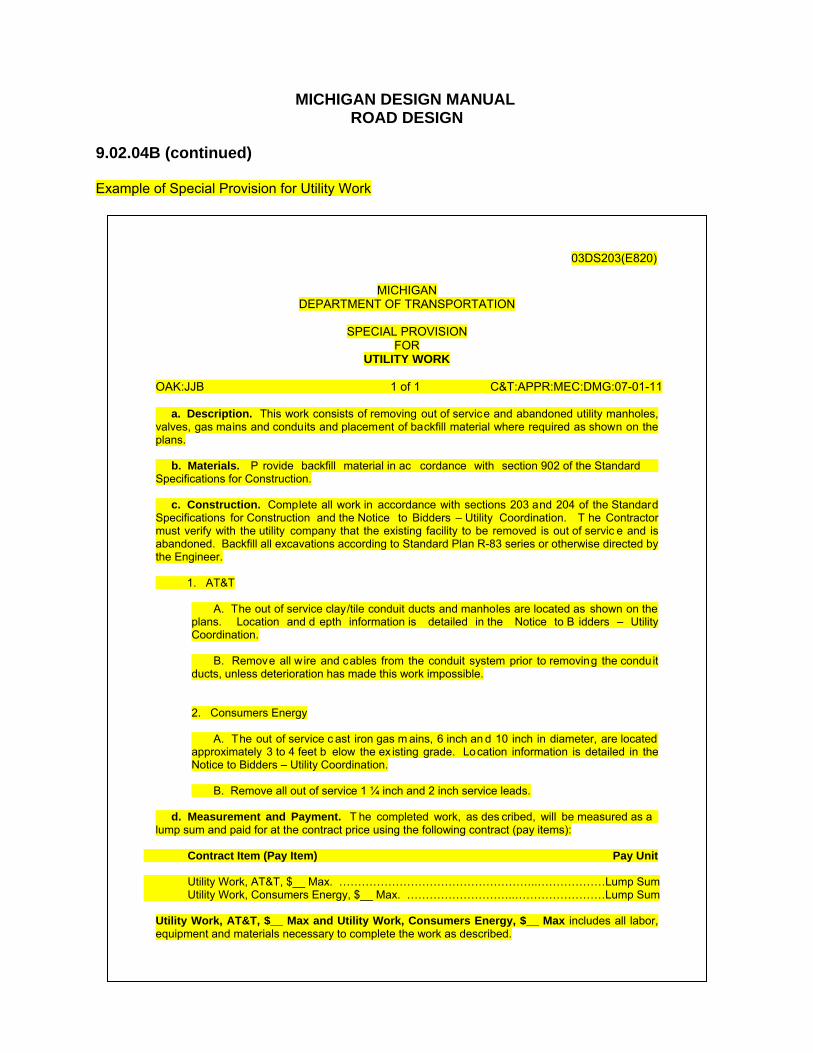
9.02.04B (continued) Example of Special Provision for Utility Work
03DS203(E820)
MICHIGAN
DEPARTMENT OF TRANSPORTATION
SPECIAL PROVISION FOR
UTILITY WORK
OAK:JJB 1 of 1 C&T:APPR:MEC:DMG:07-01-11
a. Description. This work consists of removing out of service and abandoned utility manholes, valves, gas mains and conduits and placement of backfill material where required as shown on the plans. b. Materials. P rovide backfill material in ac cordance with section 902 of the Standard Specifications for Construction. c. Construction. Complete all work in accordance with sections 203 and 204 of the Standard Specifications for Construction and the Notice to Bidders – Utility Coordination. T he Contractor must verify with the utility company that the existing facility to be removed is out of servic e and is abandoned. Backfill all excavations according to Standard Plan R-83 series or otherwise directed by the Engineer. 1. AT&T
A. The out of service clay/tile conduit ducts and manholes are located as shown on the plans. Location and d epth information is detailed in the Notice to B idders – Utility Coordination. B. Remove all wire and cables from the conduit system prior to removing the conduit ducts, unless deterioration has made this work impossible. 2. Consumers Energy A. The out of service c ast iron gas m ains, 6 inch an d 10 inch in diameter, are located approximately 3 to 4 feet b elow the ex isting grade. Location information is detailed in the Notice to Bidders – Utility Coordination. B. Remove all out of service 1 ¼ inch and 2 inch service leads.
d. Measurement and Payment. T he completed work, as des cribed, will be measured as a lump sum and paid for at the contract price using the following contract (pay items):
Contract Item (Pay Item) Pay Unit Utility Work, AT&T, $__ Max. ……………………………………………..………………Lump Sum Utility Work, Consumers Energy, $__ Max. ………………………..……………………Lump Sum
Utility Work, AT&T, $__ Max and Utility Work, Consumers Energy, $__ Max includes all labor, equipment and materials necessary to complete the work as described.

MICHIGAN DESIGN MANUAL
ROAD DESIGN
12.10.08 (revised 8-20-2012) Portable Intermittent Truck Weigh Stations (PITWS) General Information SITE SELECTION In considering the safety of officers and
passing motorists, the desired order of preference for new PITWS locations is in a rest area, a recognized Safe Enforcement Site, MDOT and county garages, carpool parking lots.
PITWS will not be permitted on a freeway shoulder. Due to traffic volume, PITWS will not be installed in the shoulder of any road unless supported by a low ADT, or installed in a recognized Safe Enforcement Site.
PITWS will not be permitted in the mainline.
The finished site must allow a minimum 3’ safe working area on all sides of a target vehicle. This area must be a reasonable grade and levelness, allowing the officer to operate safely around the target vehicle with a 12’ work area on the vehicle travel side.
Concrete pads less than 200’ shall not be installed in asphalt. However, concrete pads of at least 60’ may be installed into asphalt with a concrete base with proper anchoring into the existing concrete base.
GENERAL REQUIREMENTS PITWS LOCATION: In all cases, the PITWS shall be centered
within the joint spacing.
LANE WIDTH: A minimum of 12’, with 14’ being desirable
not including work area. See SITE SELECTION.
LANE LENGTH: The desirable length of straight pavement
is 200’ (100’ on either side of the PITWS), not including approach and departure tapers, with a minimum length of 60’ (30’ on either side of the PITWS).
12.10.08 (continued) PAVEMENT COMPOSITE & THICKNESS: It is recommended that the area meet or
exceed the thickness and composite specifications of the existing pavement slab.
New slabs, not proximate to any pavement, shall be designed consistent with the current full depth mainline concrete pavement standards.
CONCRETE REINFORCEMENT: Reinforcement is not required or
recommended, except at concrete joints, particularly in the center slab where the cut out will be located.
Concrete anchoring between poured slabs is REQUIRED on all new concrete, and between new concrete and existing concrete. All cut locations must be projected prior to pour so that proper reinforcement can be installed.
TAPER(S): Adequate tapers must be provided, before
and after the desired 200’ of straight pavement, to allow the vehicle to remain straight while on the pad. Vehicles approaching and/or leaving the 200’ pad in a straight-line need no taper(s).
Generally, 100’ of taper into the straight approach pad and 100’ of departure taper beyond the departure pad is recommended.
LEVELNESS: A concrete scale pad shall not be placed
in a vertical curve section. The desired area 100’ on both sides of the scale trench shall be preferably in one plane and within the specified grades.

MICHIGAN DESIGN MANUAL
ROAD DESIGN
12.10.08 (continued) Portable Intermittent Truck Weigh Stations (PITWS) General Information GRADE: Lateral - A zero grade is desirable, with a
maximum of 5%. Longitudinal – For newly placed slabs, as
close to a flat grade as possible is recommended to maintain stationary vehicles without brakes being applied, up to a maximum of .20%. For existing slabs a maximum of .20% is recommended.
CONDITION: All pavements, new and existing, must be
free of cracks, bumps or dips that may cause distinct elevation changes.
SMOOTHNESS Pavement surface must be level within
± 1/16” from center of slab to 30’ in either direction. The remainder of the pavement (excluding tapers) must be within ± 3/16”.
Pavement surface should receive a light broom finish. Tining is not recommended.
PAVEMENT REMOVAL (if applicable): Pavement removal, replacement,
reinforcement, and tied joint, when specified shall meet current MDOT design specifications, unless otherwise noted.
Regardless of depth, all pavement removal will be included in the pay item “Pavt, Rem”.
Standard pay items should be used for payment, however modification may be required in order to meet the requirements of this section.
12.10.08 (continued) PITWS Inspection: Contact CVST for inspection of PITWS.

MICHIGAN DESIGN MANUAL
ROAD DESIGN
12.10.08 (continued) Portable Intermittent Truck Weigh Stations (PITWS) General Information

MICHIGAN DESIGN MANUAL
ROAD DESIGN
12.10.08 (continued) Portable Intermittent Truck Weigh Stations (PITWS) General Information

MICHIGAN DESIGN MANUAL
ROAD DESIGN
12.10.08 (continued) Portable Intermittent Truck Weigh Stations (PITWS) General Information

MICHIGAN DESIGN MANUAL
ROAD DESIGN
14.54 (revised 8-20-2012) OMISSION / ERRORS / CHECK (OEC) MEETING (PPMS Task Description #3870) The Plan Completion date indicates 100% completion of the plans, proposal and supporting documents herein after referred to as the OEC package. Once Plan Completion is achieved, the Project Manager schedules a Final Plan Quality Assurance Review with the Region QA staff to internally review the OEC package for completeness. A complete OEC package is defined on MDOT Form 0330, (OEC Material Submittal Order). All items that are applicable on Form 0330 must be included with the OEC package to be considered 100% complete. The only exceptions to this list are items that are allowed to be substituted with an Exception Risk Analysis form (Form 2912) in which case the risk analysis form must be included in the OEC package. Every effort should be made to submit the project for OEC with environmental certification and approved design exceptions. Once the OEC package is acceptable, the Region Systems Manager signs Form 0330. The Project Manager may at this point schedule an OEC. The Project Manager schedules the OEC meeting electronically with a calendar appointment. The message includes the date, time and location of the meeting with a ProjectWise link to the OEC package (100% complete). The Project Manager also sends copies of the package to meeting participants that are non-ProjectWise users in an alternate deliverable and usable format (CD, hard copy, etc.) prior to the meeting. See section 14.54.02 for OEC package material content and pre-meeting review time. The purpose of this meeting is to review the entire OEC package for omissions / errors / conflicts / contradictions, etc. The Project Manager will conduct the meeting. During the course of the meeting the Project Manager will mark any needed revisions on a copy of the plans,
14.54 (continued) proposal and supporting documents. The names of those attending the meeting should be noted on the title sheet. Copies of each must remain in the project files until the project is constructed and finaled out. At the end of the meeting the Project Manager and Construction Engineer sign the title sheet and the appropriate participants sign the certification acceptance form. The Project Manager will be responsible for verifying all the agreed-upon revisions (marked in red) are incorporated into the plans. If participants at the meeting are unable to resolve a conflict, the Project Manager should report the conflict to his/her supervisor for resolution. After the conflict is resolved the Project Manager must collect any remaining signatures on the certification acceptance form or title sheet. CHANGES OR ADDITIONS TO PROJECT SCOPE OR LIMITS WILL NOT BE CONSIDERED AT THIS MEETING EXCEPT WHEN PROJECT COSTS HAVE EXCEEDED PROGRAMMED COSTS AND ADDITIONAL FUNDING IS NOT AVAILABLE. 14.54.01 (revised 8-20-2012) Attendees The following people are recommended to attend the OEC Meeting: Project Manager/Design Engineer(s) Construction Engineer Author of the Maintaining Traffic Special
Provision ( If a Consultant has authored the Maintaining Traffic Special Provision a Region/TSC Traffic and Safety Representative must be invited.). Quality Assurance Geometrics Unit Construction Field Services Division FHWA Oversight
MICHIGAN DESIGN MANUAL
ROAD DESIGN
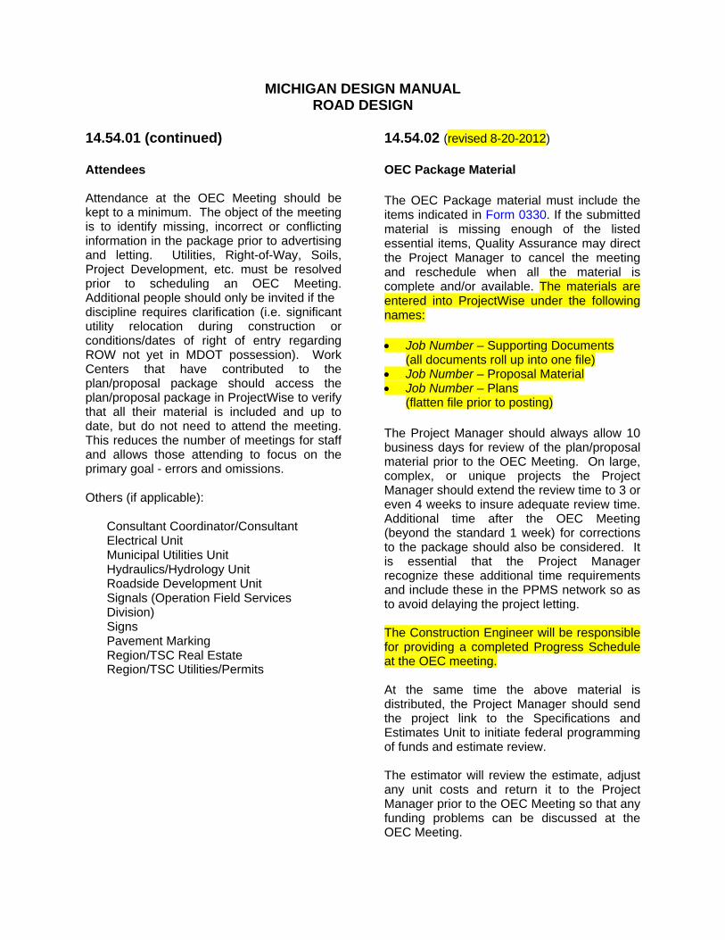
14.54.01 (continued) Attendees Attendance at the OEC Meeting should be kept to a minimum. The object of the meeting is to identify missing, incorrect or conflicting information in the package prior to advertising and letting. Utilities, Right-of-Way, Soils, Project Development, etc. must be resolved prior to scheduling an OEC Meeting. Additional people should only be invited if the discipline requires clarification (i.e. significant utility relocation during construction or conditions/dates of right of entry regarding ROW not yet in MDOT possession). Work Centers that have contributed to the plan/proposal package should access the plan/proposal package in ProjectWise to verify that all their material is included and up to date, but do not need to attend the meeting. This reduces the number of meetings for staff and allows those attending to focus on the primary goal - errors and omissions. Others (if applicable): Consultant Coordinator/Consultant Electrical Unit Municipal Utilities Unit Hydraulics/Hydrology Unit Roadside Development Unit Signals (Operation Field Services
Division) Signs Pavement Marking Region/TSC Real Estate Region/TSC Utilities/Permits
14.54.02 (revised 8-20-2012) OEC Package Material The OEC Package material must include the items indicated in Form 0330. If the submitted material is missing enough of the listed essential items, Quality Assurance may direct the Project Manager to cancel the meeting and reschedule when all the material is complete and/or available. The materials are entered into ProjectWise under the following names: Job Number – Supporting Documents
(all documents roll up into one file) Job Number – Proposal Material Job Number – Plans
(flatten file prior to posting) The Project Manager should always allow 10 business days for review of the plan/proposal material prior to the OEC Meeting. On large, complex, or unique projects the Project Manager should extend the review time to 3 or even 4 weeks to insure adequate review time. Additional time after the OEC Meeting (beyond the standard 1 week) for corrections to the package should also be considered. It is essential that the Project Manager recognize these additional time requirements and include these in the PPMS network so as to avoid delaying the project letting. The Construction Engineer will be responsible for providing a completed Progress Schedule at the OEC meeting. At the same time the above material is distributed, the Project Manager should send the project link to the Specifications and Estimates Unit to initiate federal programming of funds and estimate review. The estimator will review the estimate, adjust any unit costs and return it to the Project Manager prior to the OEC Meeting so that any funding problems can be discussed at the OEC Meeting.

MICHIGAN DESIGN MANUAL BRIDGE DESIGN - CHAPTER 7: LRFD
CHAPTER 7 DESIGN CRITERIA-NEW AND RECONSTRUCTION PROJECTS INDEX (continued) 7.02.25 Pavement Seats 7.02.26 Drain Castings 7.02.27 Sidewalks 7.02.28 Railing 7.02.29 Fencing
7.02.30 Precast Three Sided/Arch Culverts (8-20-2009) 7.02.31 Deck Replacements (11-28-2011)
7.02.32 Ride Quality (8-20-2012)
7.03 SUBSTRUCTURE 7.03.01 Abutment Design 7.03.02 Footing Design 7.03.03 Pier Design 7.03.04 Cofferdams 7.03.05 Subfootings 7.03.06 Tremie Seal Design 7.03.07 Excavation 7.03.08 Steel Sheet Piling 7.03.09 Piles 7.03.10 Slope Treatment Under End Spans 7.03.11 Concrete Sealers (5-1-2000) 7.03.12 Mechanically Stabilized Earth (MSE) Wall Requirements (8-20-2009) 7.04 STEEL REINFORCEMENT (11-28-2011) 7.04.01 Steel Reinforcement 7.04.02 Stainless Steel Reinforcement

MICHIGAN DESIGN MANUAL BRIDGE DESIGN
CHAPTER 7 DESIGN CRITERIA-NEW AND RECONSTRUCTION PROJECTS INDEX (continued) 7.02.25 Pavement Seats 7.02.26 Drain Castings 7.02.27 Sidewalks 7.02.28 Railing 7.02.29 Fencing
7.02.30 Precast Three Sided/Arch Culverts (11-28-2011) 7.02.31 Deck Replacements (11-28-2011)
7.02.32 Ride Quality (8-20-2012)
7.03 SUBSTRUCTURE 7.03.01 Abutment Design 7.03.02 Footing Design 7.03.03 Pier Design 7.03.04 Cofferdams 7.03.05 Subfootings 7.03.06 Tremie Seal Design 7.03.07 Excavation 7.03.08 Steel Sheet Piling 7.03.09 Piles 7.03.10 Slope Treatment Under End Spans 7.03.11 Concrete Sealers (5-1-2000) 7.03.12 Mechanically Stabilized Earth (MSE) Wall Requirements (11-28-2011) 7.04 STEEL REINFORCEMENT (11-28-2011) 7.04.01 Steel Reinforcement 7.04.02 Stainless Steel Reinforcement
MICHIGAN DESIGN MANUAL BRIDGE DESIGN - CHAPTER 7: LRFD
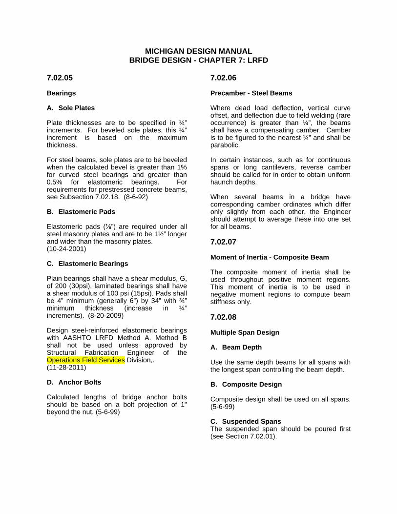
7.02.05 Bearings A. Sole Plates Plate thicknesses are to be specified in ¼” increments. For beveled sole plates, this ¼” increment is based on the maximum thickness. For steel beams, sole plates are to be beveled when the calculated bevel is greater than 1% for curved steel bearings and greater than 0.5% for elastomeric bearings. For requirements for prestressed concrete beams, see Subsection 7.02.18. (8-6-92) B. Elastomeric Pads Elastomeric pads (⅛”) are required under all steel masonry plates and are to be 1½” longer and wider than the masonry plates. (10-24-2001) C. Elastomeric Bearings Plain bearings shall have a shear modulus, G, of 200 (30psi), laminated bearings shall have a shear modulus of 100 psi (15psi). Pads shall be 4” minimum (generally 6”) by 34” with ¾” minimum thickness (increase in ¼” increments). (8-20-2009) Design steel-reinforced elastomeric bearings with AASHTO LRFD Method A. Method B shall not be used unless approved by Structural Fabrication Engineer of the Operations Field Services Division,. (11-28-2011) D. Anchor Bolts Calculated lengths of bridge anchor bolts should be based on a bolt projection of 1" beyond the nut. (5-6-99)
7.02.06 Precamber - Steel Beams Where dead load deflection, vertical curve offset, and deflection due to field welding (rare occurrence) is greater than ¼”, the beams shall have a compensating camber. Camber is to be figured to the nearest ¼” and shall be parabolic. In certain instances, such as for continuous spans or long cantilevers, reverse camber should be called for in order to obtain uniform haunch depths. When several beams in a bridge have corresponding camber ordinates which differ only slightly from each other, the Engineer should attempt to average these into one set for all beams. 7.02.07 Moment of Inertia - Composite Beam The composite moment of inertia shall be used throughout positive moment regions. This moment of inertia is to be used in negative moment regions to compute beam stiffness only. 7.02.08 Multiple Span Design A. Beam Depth Use the same depth beams for all spans with the longest span controlling the beam depth. B. Composite Design Composite design shall be used on all spans. (5-6-99) C. Suspended Spans The suspended span should be poured first (see Section 7.02.01).

MICHIGAN DESIGN MANUAL BRIDGE DESIGN - CHAPTER 7: LRFD
7.02.19 Slabs For information on Ride Quality on new slabs see section 7.02.32 A. Design (8-20-2009) MDOT standard LRFD slab is designed using the following criteria: 1. The design loads for decks and deck
systems should be specified depending on the method of analysis. When the approximate strip method is used, force effects should be determined on the following basis:
a. Where primary strips are
transverse and their span does not exceed 15.0 ft., the transverse strip shall be designed for the wheels of the 32.0-kip axle.
b. Where primary strips are transverse
and their span exceeds 15.0 ft., the transverse strip shall be designed for the wheels of the 32.0-kip axle and the lane load together.
c. Where primary strips are longitudinal,
the transverse strips shall be designed for all loads specified above, including the lane load.
2. The design truck shall be positioned
transversally such that the center of any wheel load is not closer than:
a. One foot (1.0 ft.) from the face of the
curb or railing for the design of the deck overhang.
b. Two Feet ( 2.0 ft.) from the edge of the
design lane for the design of all other components.
3. Where the strip method is used, the
extreme positive moment in any deck panel between girders shall be taken to apply to all positive moment regions. The extreme negative moment over any girder shall be taken to apply to all negative moment regions.
7.02.19 (continued) 4. Top 1½” of slab is considered a wearing
surface and is not included in the design depth.
Design of deck slabs using the Empirical Design Method according to A 9.7.2 AASHTO LRFD is an approved or allowed alternative. B. Overhang Design overhang according to A 9.7.1.5 AASHTO LRFD. If the deck overhang with cantilever does not exceed 6.0 ft. from the centerline of the exterior girder to the face of a structurally continuous concrete railing, the outside row of wheel loads may be replaced with a uniformly distributed line load of 1.0 klf intensity, located 1.0 ft. from the face of the railing. (8-20-2009) For standard overhang, see Bridge Design Guides 6.29.07 through 6.29.09. Overhangs greater than standard should be avoided, if possible. If not, the slab design shall be checked in this region for negative movement. C. Slab Haunches Plans are to provide for the deck slab to be haunched at each beam to provide for variance in actual top of beams. The design should normally make allowance for a 1" uniform haunch for steel beam bridges and a 2" minimum haunch for prestressed concrete beam bridges; however, the details should show the haunch as variable. A nominal 2" haunch should be used on structures with span lengths exceeding 100'-0". To aid in the construction of the haunched slab, the plans should include bottom of slab elevations over each beam and at equal intervals across the spans. These elevations should apply at the time that all structural steel has been erected, but no other loads applied; however, they should include allowance for additional deflection due to forms, steel reinforcement, deck concrete, and railing. For additional criteria when the haunch exceeds 6” see section 7.02.20 G. and Bridge Design Guide 6.42.03A. (5-6-99) (4-23-2012)

MICHIGAN DESIGN MANUAL BRIDGE DESIGN
7.02.19 Slabs For information on Ride Quality on new slabs see section 7.02.32 A. Design Our standard slab (see Bridge Design Guide 6.41.01) is designed using the following criteria: 1. HS20-44 loading (16kip wheel). 2. Continuous over three or more beams of
similar structural capacity. 3. Load Factor design method. (5-6-99) 4. Top 1½” of slab is considered a wearing
surface and is not included in the design depth.
B. Overhang For standard overhang, see Bridge Design Guides 6.29.07 through 6.29.09. Overhangs greater than standard should be avoided, if possible. If not, the slab design shall be checked in this region for negative movement. C. Slab Haunches Plans are to provide for the deck slab to be haunched at each beam to provide for variance in actual top of beams. The design should normally make allowance for a 1" uniform haunch for steel beam bridges and a 2" minimum haunch for prestressed concrete beam bridges; however, the details should show the haunch as variable. A nominal 2" haunch should be used on structures with span lengths exceeding 100'-0". To aid in the construction of the haunched slab, the plans should include bottom of slab elevations over each beam and at equal intervals across the spans. These elevations should apply at the time that all structural steel has been erected, but no other loads applied; however, they should include allowance for additional deflection due to forms, steel reinforcement, deck concrete, and railing. For additional criteria when the haunch exceeds 6” see section 7.02.20 G. and Bridge Design Guide 6.42.03A. (5-6-99) (4-23-2012)
7.02.19 (continued) D. Slab Thicknesses Slab thicknesses are to be according to Bridge Design Guide 6.41.01 and are to be uniform thickness with beams stepped to follow the crown of the roadway. E. Slab Under Sidewalk If the roadway slab extends underneath the sidewalk, it should be designed for full highway loading. F. Nighttime Casting of Superstructure
Concrete All bridge deck pours are to be designated nighttime casting of superstructure concrete on all bridge decks. (5-6-99) G. Bridge Crown/Slope Use 2% cross-slope on all projects with a deck replacement or greater scope except those that have compelling reasons to meet the existing cross-slope. Maintain constant slope across lanes of travel and shoulders, including bridges with full superelevation and ramp bridges. This will allow for ease of construction and deck screeding. Bridge overlays and railroad and bridge approach projects may use 1.5 %. Local roads over may also use 1.5% unless the road approaches are or may become 2%. Parabolic crowns being overlayed should be corrected to a minimum of 1.5%; otherwise a design exception must be submitted. Deck replacement bridges with parabolic crowns shall be corrected to a 2% cross-slope. (12-5-2005) The road approach shoulder slope shall be transitioned to meet the bridge shoulder slope. The transition shall be based on superelevation transition slope (Δ%) from Standard Plan R-107 Series. The procedure is outlined in section 6.05.05 of the Road Design Manual. (8-20-2009) (11-28-2011)

MICHIGAN DESIGN MANUAL BRIDGE DESIGN - CHAPTER 7: LRFD
7.02.32 Ride Quality (8-20-2012) The purpose of a ride quality specification is to obtain a smoother riding pavement than is typically obtained with the traditional 10 foot straightedge smoothness requirements. Michigan first adopted a ride quality specification in 1979. The current specification prescribes classified levels of ride quality requirements described in subsequent paragraphs of this section. Specific requirements for ride quality are identified by classification. Each classification (Class I, II, III & IV) specifies criteria for roughness, method of measurement, applicable incentives, disincentives, and corrective action. The matrix on the following page provides instructions for assigning ride quality classification based on scope of work, design speed, grade control and adaptability to production paving. Ride quality requirements are not intended for application with stand-alone bridge projects. However, bridge deck replacements, and shallow or deep concrete bridge overlays included within the limits of a Class I ride quality section in a corridor project will be subject to ride quality requirements. Using these criteria, the road designer will assign a ride quality classification to each applicable section of paving throughout the project. The locations and classifications are then tabulated for inclusion in the Notice to Bidders (generally done by the road designer). The bridge designer will recommend if the bridge portions of a Class I section are to also be designated as Class I or are to be excluded by designation as Class II based on the type of work and adaptability to corrective deck grinding, Within Class II, III, and IV areas, bridges are predetermined excluded areas from ride quality specifications between the two end reference lines or between the outermost limits of any structure expansion joint devices.
7.02.32 (continued) The only pay item associated with ride quality is bump grinding. A small quantity should be included for each location where the contractor may be directed to grind existing pavement (i.e.: pavement not placed as part of the contract) in order to smooth the transition from old to new pavement. This includes the POB, the POE, and any existing bridge or railroad approaches within the project limits. 25 square yards for each lane at each of the above locations should suffice. Bump grinding is normally not paid for in areas excluded from ride quality. Instead the pavement is accepted or rejected based on the 10 foot straightedge criteria. (Standard Specifications for Construction) If it does not meet the straightedge criteria, it is the contractor’s responsibility to grind or replace at their cost. For additional information on ride quality see the Road Design Manual section 6.04.05.

MICHIGAN DESIGN MANUAL
BRIDGE DESIGN – CHAPTER 7:LRFD
7.02.32 (continued)
Rid
e Q
ualit
y C
lass
ifica
tion
Sele
ctio
n M
atrix
Co
ntr
act
or
has
limite
d or
no
cont
rol (2
) ov
er
gra
des
Fle
xibl
e
Ultr
a T
hin,
P
aver
P
lace
d S
urfa
ce
Sea
l
Cla
ss I
II
Cla
ss I
II
Cla
ss IV
Cla
ss IV
Ke
y:
Cla
ss I
Rid
e Q
ual
ity:
Co
mp
lete
Pro
ject
s (m
ain
line
on
ly)
whe
re n
o e
xclu
de
d ar
eas
are
allo
we
d,
a th
resh
ho
ld I
RI
crite
ria m
ust
be
me
t, an
d i
nce
ntiv
es
and
dis
ince
ntiv
es
app
ly.
Use
C
lass
I o
nly
on
lim
ited
acc
ess
road
wa
y w
ith d
esig
n s
pee
ds 5
0 m
ph
or
gre
ate
r a
nd w
her
e m
ost
or
all b
ridge
s in
clu
de d
eck
rep
lace
men
t, s
hal
low
co
ncre
te o
verla
ys,
or
dee
p c
onc
rete
o
verla
ys.
Inve
stig
ate
the
fe
asib
ility
of
dia
mon
d g
rind
ing
(a
t M
DO
T c
ost
) a
ny b
ridge
de
cks
not
be
ing
rep
lace
d o
r o
verla
id.
Wh
ere
dia
mo
nd g
rind
ing
a b
ridg
e de
ck i
s n
ot
fea
sib
le,
a
limite
d s
ectio
n o
f th
e p
roje
ct c
an b
e d
esi
gned
as
Cla
ss I
I R
ide
Qua
lity
such
th
at t
he
brid
ge w
ou
ld b
e a
pre
-de
term
ined
exc
lude
d a
rea
with
in a
pro
ject
th
at
wou
ld o
ther
wis
e m
ee
t C
lass
I
ride
Qu
alit
y cr
iteria
. C
lass
II
Rid
e Q
ual
ity: S
ect
ion
s w
he
re t
hres
hold
IR
I crit
eria
mus
t be
me
t, b
ut i
ncen
tives
an
d d
isin
cen
tives
do
no
t app
ly. (
Use
Cla
ss I
I if a
ll o
f the
ab
ove
req
uire
men
ts f
or
Cla
ss I
are
no
t m
et.)
C
lass
III
Rid
e Q
ualit
y: S
ect
ion
s w
her
e th
e p
re-c
ons
truc
tion
IRI
mu
st b
e m
ain
tain
ed o
r im
pro
ved
by a
ce
rta
in p
erc
ent
age
. Dis
ince
ntiv
es m
ay
app
ly.
Cla
ss I
V R
ide
Qua
lity:
Sec
tions
whe
re a
cce
pta
nce
is b
ase
d on
a 1
0 fo
ot s
tra
ight
edge
cri
teria
. In
cent
ive
s an
d d
isin
cen
tive
s d
o n
ot a
pp
ly.
N/A
= N
ot A
pplic
able
F
oo
tno
tes:
(1
) A
Se
ctio
n is
def
ine
d a
s a
leng
th o
f pa
ving
wh
ich
has
the
sam
e c
hara
cte
ristic
s (g
rad
e c
ontr
ol,
type
of
wor
k, d
esi
gn s
pee
d).
(2)
Lo
catio
ns w
her
e a
con
tra
cto
r m
ight
no
t ha
ve c
ontr
ol
of
gra
des
inc
lude
lo
catio
ns w
he
re t
he
y m
ust
pave
ad
jace
nt
to a
n e
xist
ing
la
ne w
ith m
arg
ina
l ri
de q
ua
lity,
loc
atio
ns
wh
ere
the
re a
re e
xist
ing
cu
rbs
to m
atc
h, a
nd lo
catio
ns w
her
e th
ere
are
freq
uen
t exi
stin
g m
an
hole
s o
r st
ruct
ure
s to
me
et.
(3)
3R
me
ans
resu
rfa
cin
g,
rest
ora
tion
, a
nd
reh
abili
tatio
n.
Pri
mar
y e
xam
ple
s in
clu
de m
ulti
ple
cou
rse
re
surf
aci
ng
, m
illin
g o
r p
rofil
ing,
co
ncre
te o
verla
ys a
nd
in
lays
(w
ithou
t
re
mov
ing
sub
base
).4
R m
ea
ns n
ew
co
nstr
uct
ion
or
reco
nstr
uctio
n.
A p
rima
ry e
xam
ple
is c
om
ple
te r
em
ova
l an
d r
epla
cem
ent
of
pav
em
en
t (in
clu
din
g s
ubb
ase)
. S
ee
Ch
apte
r
3
for
furt
her
de
finiti
on
and
exa
mp
les
incl
udi
ng p
roje
cts
with
co
mbi
ned
3R
and
4R
wo
rk fo
r cl
ass
ifica
tion
s pu
rpo
ses
on
pro
ject
s w
ith m
ultip
le f
ixes
. (4
) P
rod
uctio
n p
avin
g m
ea
ns
a s
lipfo
rm p
ave
r ca
n b
e u
sed
fo
r co
ncre
te p
avin
g a
nd
th
at
a H
MA
pa
ver
can
be
use
d w
ithou
t fr
equ
en
t st
opp
ing
an
d s
tart
ing
an
d t
her
e is
roo
m f
or
a h
au
l tr
uck
to u
nlo
ad d
irect
ly i
nto
th
e p
ave
r o
r a
mat
eria
l tr
ansf
er
dev
ice
wh
ile i
n m
otio
n.
MD
OT
im
po
sed
co
nstr
uct
ion
sta
gin
g r
equ
irem
ents
sho
uld
be
co
nsid
ere
d w
hen
ma
kin
g th
is d
ete
rmin
atio
n
Dia
mo
nd
Gri
ndi
ng
Pro
ject
s
Cla
ss I
II
Cla
ss I
II
N/A
N/A
Sin
gle
C
ou
rse
of
Fle
xib
le
Pa
vem
ent
(with
/with
ou
t m
illin
g)
Cla
ss I
II
Cla
ss I
II
Cla
ss IV
Cla
ss IV
4R
(3)
Cla
ss II
Cla
ss II
Cla
ss IV
Cla
ss IV
3R
(3)
Cla
ss II
Cla
ss II
Cla
ss IV
Cla
ss IV
Co
ntr
act
or
has
cont
rol o
ver
grad
es
4R
(3)
Cla
ss II
Cla
ss I
or
II
Cla
ss II
Cla
ss I
or
II
3R
(3)
Cla
ss II
Cla
ss I
or
II
Cla
ss I
II
Cla
ss II
How
To
Use
Thi
s M
atrix
Div
ide
th
e p
roje
ct i
nto
Se
ctio
ns
(1) b
ase
d o
n t
he a
mo
unt
of
con
tro
l th
e co
ntr
acto
r w
ill h
ave
ove
r th
e f
ina
l su
rfac
e g
rade
s, t
he s
cop
e of
w
ork
, an
d
the
de
sig
n
spee
d.
Det
erm
ine
th
e
reco
mm
en
ded
rid
e sp
ecifi
catio
n t
ype
for
eac
h s
ect
ion
. C
on
fer
with
Co
nstr
uct
ion
Fie
ld
Se
rvic
es s
taff
for
exc
ept
ion
s or
un
iqu
e c
ircu
mst
ance
s.
De
sign
Spe
ed b
elo
w 5
0 m
ph
De
sign
Spe
ed 5
0 m
ph
or
abo
ve
De
sign
Spe
ed b
elo
w 5
0 m
ph
De
sign
Spe
ed 5
0 m
ph
or
abo
ve
Se
ctio
n le
ng
th a
llow
s fo
r p
rod
uctio
n pa
vin
g (4
)
Se
ctio
n le
ng
th d
oes
not
allo
w p
rodu
ctio
n p
avi
ng
(4)

MICHIGAN DESIGN MANUAL BRIDGE DESIGN
7.02.32 Ride Quality (8-20-2012) The purpose of a ride quality specification is to obtain a smoother riding pavement than is typically obtained with the traditional 10 foot straightedge smoothness requirements. Michigan first adopted a ride quality specification in 1979. The current specification prescribes classified levels of ride quality requirements described in subsequent paragraphs of this section. Specific requirements for ride quality are identified by classification. Each classification (Class I, II, III & IV) specifies criteria for roughness, method of measurement, applicable incentives, disincentives, and corrective action. The matrix on the following page provides instructions for assigning ride quality classification based on scope of work, design speed, grade control and adaptability to production paving. Ride quality requirements are not intended for application with stand-alone bridge projects. However, bridge deck replacements, and shallow or deep concrete bridge overlays included within the limits of a Class I ride quality section in a corridor project will be subject to ride quality requirements. Using these criteria, the road designer will assign a ride quality classification to each applicable section of paving throughout the project. The locations and classifications are then tabulated for inclusion in the Notice to Bidders (generally done by the road designer). The bridge designer will recommend if the bridge portions of a Class I section are to also be designated as Class I or are to be excluded by designation as Class II based on the type of work and adaptability to corrective deck grinding, Within Class II, III, and IV areas, bridges are predetermined excluded areas from ride quality specifications between the two end reference lines or between the outermost limits of any structure expansion joint devices.
7.02.32 (continued) The only pay item associated with ride quality is bump grinding. A small quantity should be included for each location where the contractor may be directed to grind existing pavement (i.e.: pavement not placed as part of the contract) in order to smooth the transition from old to new pavement. This includes the POB, the POE, and any existing bridge or railroad approaches within the project limits. 25 square yards for each lane at each of the above locations should suffice. Bump grinding is normally not paid for in areas excluded from ride quality. Instead the pavement is accepted or rejected based on the 10 foot straightedge criteria. (Standard Specifications for Construction) If it does not meet the straightedge criteria, it is the contractor’s responsibility to grind or replace at their cost. For additional information on ride quality see the Road Design Manual section 6.04.05.

MICHIGAN DESIGN MANUAL
BRIDGE DESIGN
7.02.32 (continued)
Rid
e Q
ualit
y C
lass
ifica
tion
Sele
ctio
n M
atrix
Co
ntr
act
or
has
limite
d or
no
cont
rol (2
) ov
er
gra
des
Fle
xibl
e
Ultr
a T
hin,
P
aver
P
lace
d S
urfa
ce
Sea
l
Cla
ss I
II
Cla
ss I
II
Cla
ss IV
Cla
ss IV
Ke
y:
Cla
ss I
Rid
e Q
ual
ity:
Co
mp
lete
Pro
ject
s (m
ain
line
on
ly)
whe
re n
o e
xclu
de
d ar
eas
are
allo
we
d,
a th
resh
ho
ld I
RI
crite
ria m
ust
be
me
t, an
d i
nce
ntiv
es
and
dis
ince
ntiv
es
app
ly.
Use
C
lass
I o
nly
on
lim
ited
acc
ess
road
wa
y w
ith d
esig
n s
pee
ds 5
0 m
ph
or
gre
ate
r a
nd w
her
e m
ost
or
all b
ridge
s in
clu
de d
eck
rep
lace
men
t, s
hal
low
co
ncre
te o
verla
ys,
or
dee
p c
onc
rete
o
verla
ys.
Inve
stig
ate
the
fe
asib
ility
of
dia
mon
d g
rind
ing
(a
t M
DO
T c
ost
) a
ny b
ridge
de
cks
not
be
ing
rep
lace
d o
r o
verla
id.
Wh
ere
dia
mo
nd g
rind
ing
a b
ridg
e de
ck i
s n
ot
fea
sib
le,
a
limite
d s
ectio
n o
f th
e p
roje
ct c
an b
e d
esi
gned
as
Cla
ss I
I R
ide
Qua
lity
such
th
at t
he
brid
ge w
ou
ld b
e a
pre
-de
term
ined
exc
lude
d a
rea
with
in a
pro
ject
th
at
wou
ld o
ther
wis
e m
ee
t C
lass
I
ride
Qu
alit
y cr
iteria
. C
lass
II
Rid
e Q
ual
ity: S
ect
ion
s w
he
re t
hres
hold
IR
I crit
eria
mus
t be
me
t, b
ut i
ncen
tives
an
d d
isin
cen
tives
do
no
t app
ly. (
Use
Cla
ss I
I if a
ll o
f the
ab
ove
req
uire
men
ts f
or
Cla
ss I
are
no
t m
et.)
C
lass
III
Rid
e Q
ualit
y: S
ect
ion
s w
her
e th
e p
re-c
ons
truc
tion
IRI
mu
st b
e m
ain
tain
ed o
r im
pro
ved
by a
ce
rta
in p
erc
ent
age
. Dis
ince
ntiv
es m
ay
app
ly.
Cla
ss I
V R
ide
Qua
lity:
Sec
tions
whe
re a
cce
pta
nce
is b
ase
d on
a 1
0 fo
ot s
tra
ight
edge
cri
teria
. In
cent
ive
s an
d d
isin
cen
tive
s d
o n
ot a
pp
ly.
N/A
= N
ot A
pplic
able
F
oo
tno
tes:
(1
) A
Se
ctio
n is
def
ine
d a
s a
leng
th o
f pa
ving
wh
ich
has
the
sam
e c
hara
cte
ristic
s (g
rad
e c
ontr
ol,
type
of
wor
k, d
esi
gn s
pee
d).
(2)
Lo
catio
ns w
her
e a
con
tra
cto
r m
ight
no
t ha
ve c
ontr
ol
of
gra
des
inc
lude
lo
catio
ns w
he
re t
he
y m
ust
pave
ad
jace
nt
to a
n e
xist
ing
la
ne w
ith m
arg
ina
l ri
de q
ua
lity,
loc
atio
ns
wh
ere
the
re a
re e
xist
ing
cu
rbs
to m
atc
h, a
nd lo
catio
ns w
her
e th
ere
are
freq
uen
t exi
stin
g m
an
hole
s o
r st
ruct
ure
s to
me
et.
(3)
3R
me
ans
resu
rfa
cin
g,
rest
ora
tion
, a
nd
reh
abili
tatio
n.
Pri
mar
y e
xam
ple
s in
clu
de m
ulti
ple
cou
rse
re
surf
aci
ng
, m
illin
g o
r p
rofil
ing,
co
ncre
te o
verla
ys a
nd
in
lays
(w
ithou
t
re
mov
ing
sub
base
).4
R m
ea
ns n
ew
co
nstr
uct
ion
or
reco
nstr
uctio
n.
A p
rima
ry e
xam
ple
is c
om
ple
te r
em
ova
l an
d r
epla
cem
ent
of
pav
em
en
t (in
clu
din
g s
ubb
ase)
. S
ee
Ch
apte
r
3
for
furt
her
de
finiti
on
and
exa
mp
les
incl
udi
ng p
roje
cts
with
co
mbi
ned
3R
and
4R
wo
rk fo
r cl
ass
ifica
tion
s pu
rpo
ses
on
pro
ject
s w
ith m
ultip
le f
ixes
. (4
) P
rod
uctio
n p
avin
g m
ea
ns
a s
lipfo
rm p
ave
r ca
n b
e u
sed
fo
r co
ncre
te p
avin
g a
nd
th
at
a H
MA
pa
ver
can
be
use
d w
ithou
t fr
equ
en
t st
opp
ing
an
d s
tart
ing
an
d t
her
e is
roo
m f
or
a h
au
l tr
uck
to u
nlo
ad d
irect
ly i
nto
th
e p
ave
r o
r a
mat
eria
l tr
ansf
er
dev
ice
wh
ile i
n m
otio
n.
MD
OT
im
po
sed
co
nstr
uct
ion
sta
gin
g r
equ
irem
ents
sho
uld
be
co
nsid
ere
d w
hen
ma
kin
g th
is d
ete
rmin
atio
n
Dia
mo
nd
Gri
ndi
ng
Pro
ject
s
Cla
ss I
II
Cla
ss I
II
N/A
N/A
Sin
gle
C
ou
rse
of
Fle
xib
le
Pa
vem
ent
(with
/with
ou
t m
illin
g)
Cla
ss I
II
Cla
ss I
II
Cla
ss IV
Cla
ss IV
4R
(3)
Cla
ss II
Cla
ss II
Cla
ss IV
Cla
ss IV
3R
(3)
Cla
ss II
Cla
ss II
Cla
ss IV
Cla
ss IV
Co
ntr
act
or
has
cont
rol o
ver
grad
es
4R
(3)
Cla
ss II
Cla
ss I
or
II
Cla
ss II
Cla
ss I
or
II
3R
(3)
Cla
ss II
Cla
ss I
or
II
Cla
ss I
II
Cla
ss II
How
To
Use
Thi
s M
atrix
Div
ide
th
e p
roje
ct i
nto
Se
ctio
ns
(1) b
ase
d o
n t
he a
mo
unt
of
con
tro
l th
e co
ntr
acto
r w
ill h
ave
ove
r th
e f
ina
l su
rfac
e g
rade
s, t
he s
cop
e of
w
ork
, an
d
the
de
sig
n
spee
d.
Det
erm
ine
th
e
reco
mm
en
ded
rid
e sp
ecifi
catio
n t
ype
for
eac
h s
ect
ion
. C
on
fer
with
Co
nstr
uct
ion
Fie
ld
Se
rvic
es s
taff
for
exc
ept
ion
s or
un
iqu
e c
ircu
mst
ance
s.
De
sign
Spe
ed b
elo
w 5
0 m
ph
De
sign
Spe
ed 5
0 m
ph
or
abo
ve
De
sign
Spe
ed b
elo
w 5
0 m
ph
De
sign
Spe
ed 5
0 m
ph
or
abo
ve
Se
ctio
n le
ng
th a
llow
s fo
r p
rod
uctio
n pa
vin
g (4
)
Se
ctio
n le
ng
th d
oes
not
allo
w p
rodu
ctio
n p
avi
ng
(4)
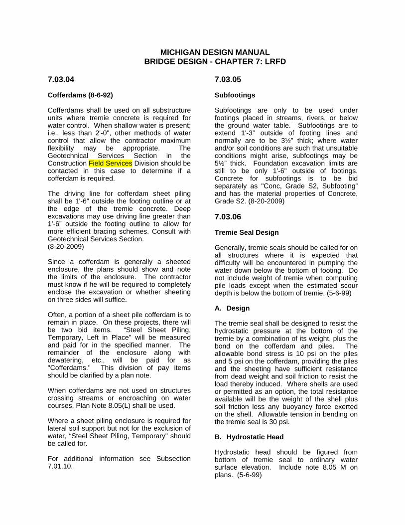
MICHIGAN DESIGN MANUAL BRIDGE DESIGN - CHAPTER 7: LRFD
7.03.04 Cofferdams (8-6-92) Cofferdams shall be used on all substructure units where tremie concrete is required for water control. When shallow water is present; i.e., less than 2'-0", other methods of water control that allow the contractor maximum flexibility may be appropriate. The Geotechnical Services Section in the Construction Field Services Division should be contacted in this case to determine if a cofferdam is required. The driving line for cofferdam sheet piling shall be 1'-6” outside the footing outline or at the edge of the tremie concrete. Deep excavations may use driving line greater than 1’-6” outside the footing outline to allow for more efficient bracing schemes. Consult with Geotechnical Services Section. (8-20-2009) Since a cofferdam is generally a sheeted enclosure, the plans should show and note the limits of the enclosure. The contractor must know if he will be required to completely enclose the excavation or whether sheeting on three sides will suffice. Often, a portion of a sheet pile cofferdam is to remain in place. On these projects, there will be two bid items. “Steel Sheet Piling, Temporary, Left in Place" will be measured and paid for in the specified manner. The remainder of the enclosure along with dewatering, etc., will be paid for as "Cofferdams." This division of pay items should be clarified by a plan note. When cofferdams are not used on structures crossing streams or encroaching on water courses, Plan Note 8.05(L) shall be used. Where a sheet piling enclosure is required for lateral soil support but not for the exclusion of water, “Steel Sheet Piling, Temporary" should be called for. For additional information see Subsection 7.01.10.
7.03.05 Subfootings Subfootings are only to be used under footings placed in streams, rivers, or below the ground water table. Subfootings are to extend 1'-3” outside of footing lines and normally are to be 3½” thick; where water and/or soil conditions are such that unsuitable conditions might arise, subfootings may be 5½” thick. Foundation excavation limits are still to be only 1'-6" outside of footings. Concrete for subfootings is to be bid separately as "Conc, Grade S2, Subfooting” and has the material properties of Concrete, Grade S2. (8-20-2009) 7.03.06 Tremie Seal Design Generally, tremie seals should be called for on all structures where it is expected that difficulty will be encountered in pumping the water down below the bottom of footing. Do not include weight of tremie when computing pile loads except when the estimated scour depth is below the bottom of tremie. (5-6-99) A. Design The tremie seal shall be designed to resist the hydrostatic pressure at the bottom of the tremie by a combination of its weight, plus the bond on the cofferdam and piles. The allowable bond stress is 10 psi on the piles and 5 psi on the cofferdam, providing the piles and the sheeting have sufficient resistance from dead weight and soil friction to resist the load thereby induced. Where shells are used or permitted as an option, the total resistance available will be the weight of the shell plus soil friction less any buoyancy force exerted on the shell. Allowable tension in bending on the tremie seal is 30 psi. B. Hydrostatic Head Hydrostatic head should be figured from bottom of tremie seal to ordinary water surface elevation. Include note 8.05 M on plans. (5-6-99)

MICHIGAN DESIGN MANUAL BRIDGE DESIGN
7.03.04 Cofferdams (8-6-92) Cofferdams shall be used on all substructure units where tremie concrete is required for water control. When shallow water is present; i.e., less than 2'-0", other methods of water control that allow the contractor maximum flexibility may be appropriate. The Geotechnical Services Section in the Construction Field Services Division should be contacted in this case to determine if a cofferdam is required. The driving line for cofferdam sheet piling shall be 1'-6” outside the footing outline or at the edge of the tremie concrete. Deep excavations may use driving line greater than 1’-6” outside the footing outline to allow for more efficient bracing schemes. Consult with Geotechnical Services Section. (11-28-2011) Since a cofferdam is generally a sheeted enclosure, the plans should show and note the limits of the enclosure. The contractor must know if he will be required to completely enclose the excavation or whether sheeting on three sides will suffice. Often, a portion of a sheet pile cofferdam is to remain in place. On these projects, there will be two bid items. “Steel Sheet Piling, Temporary, Left in Place" will be measured and paid for in the specified manner. The remainder of the enclosure along with dewatering, etc., will be paid for as "Cofferdams." This division of pay items should be clarified by a plan note. When cofferdams are not used on structures crossing streams or encroaching on water courses, Plan Note 8.05(L) shall be used. Where a sheet piling enclosure is required for lateral soil support but not for the exclusion of water, “Steel Sheet Piling, Temporary" should be called for. For additional information see Subsection 7.01.10.
7.03.05 Subfootings Subfootings are only to be used under footings placed in streams, rivers, or below the ground water table. Subfootings are to extend 1'-3” outside of footing lines and normally are to be 3½” thick; where water and/or soil conditions are such that unsuitable conditions might arise, subfootings may be 5½” thick. Foundation excavation limits are still to be only 1'-6" outside of footings. Concrete for subfootings is to be bid separately as "Conc, Grade S2, Subfooting” and has the material properties of Concrete, Grade S2. (11-28-2011) 7.03.06 Tremie Seal Design Generally, tremie seals should be called for on all structures where it is expected that difficulty will be encountered in pumping the water down below the bottom of footing. Do not include weight of tremie when computing pile loads except when the estimated scour depth is below the bottom of tremie. (5-6-99) A. Design The tremie seal shall be designed to resist the hydrostatic pressure at the bottom of the tremie by a combination of its weight, plus the bond on the cofferdam and piles. The allowable bond stress is 10 psi on the piles and 5 psi on the cofferdam, providing the piles and the sheeting have sufficient resistance from dead weight and soil friction to resist the load thereby induced. Where shells are used or permitted as an option, the total resistance available will be the weight of the shell plus soil friction less any buoyancy force exerted on the shell. Allowable tension in bending on the tremie seal is 30 psi. B. Hydrostatic Head Hydrostatic head should be figured from bottom of tremie seal to ordinary water surface elevation. Include note 8.05 M on plans. (5-6-99)

MICHIGAN DESIGN MANUAL BRIDGE DESIGN - CHAPTER 7: LRFD
7.03.08 (continued) D. Permanent Steel Sheet Piling (10-24-2001) 1. Design A required section modulus is calculated
based upon a piling design. (MDOT Construction Field Services Geotechnical Services Section may recommend a section modulus.) A section is chosen from Appendix 7.03.08 D. (Sheet Piling Section Moduli) using the tabulated “effective” modulus in place of the calculated section modulus.
Cold rolled sections have an additional
reduction factor, thus it is possible to have a cold rolled section with a higher nominal section modulus, but a lower effective section modulus. To avoid field substitutions resulting in less than designed “effective” section modulus, the plans shall indicate the minimum acceptable nominal section modulus for both hot and cold rolled sections based on values given in Appendix 7.03.08 D. (see note 8.06.07C).
In addition to Appendix 7.03.08 D., which
is to be used for all permanent installations, sheet piling sections subject to severe environments should also be hot dipped galvanized.
Designers are responsible to determine
the availability of the sheet piling sections they specify.
7.03.08 (continued) 2. Background/Commentary Appendix 7.03.08 D. was developed by
the Illinois DOT. It contains sheet pile sections and their effective section modus. This effective modulus was calculated by reducing the nominal value for the effects of corrosion, and in some cases for a Hartman reduction factor.
Hartman Reduction Factor - tests by
Hartman Engineering indicate that cold rolled sections failed at 83% of the expected value based on conventional bending theory. The Hartman study concluded that these failures were because the cold rolled sections have larger widths, depths, and width to depth ratios which promote failure prior to yielding the tension flanges. Cold rolled sections shown on the table have their section modulus reduced by 17% to account for the lower yield values. Illinois DOT took the report’s conclusion a further step and applied the Hartman reduction factor to “light duty” hot rolled sections also.
Corrosion - all tabulated sections were
reduced to mitigate the effects of corrosion. Illinois DOT assumed a 50 year service life and a corrosion of about 0.00059 inches per year. This translates to about 1/17" of total corrosion (two sides) for the service life.
MDOT requires a 75 year service life and
a slightly higher corrosion rate, thus the requirement for hot dipped galvanized sections in severe environments.
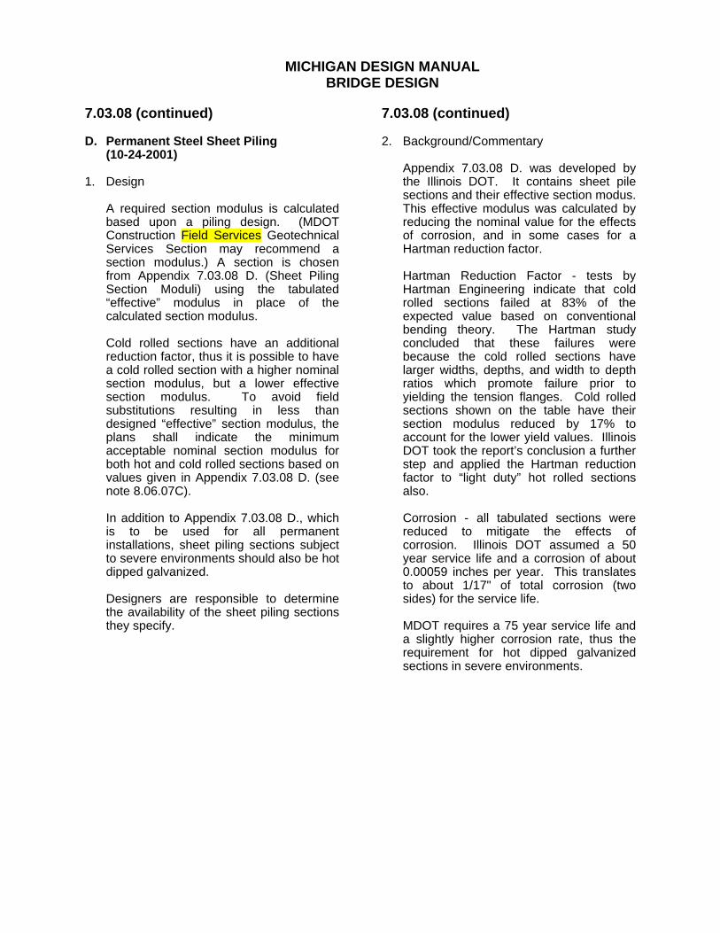
MICHIGAN DESIGN MANUAL BRIDGE DESIGN
7.03.08 (continued) D. Permanent Steel Sheet Piling (10-24-2001) 1. Design A required section modulus is calculated
based upon a piling design. (MDOT Construction Field Services Geotechnical Services Section may recommend a section modulus.) A section is chosen from Appendix 7.03.08 D. (Sheet Piling Section Moduli) using the tabulated “effective” modulus in place of the calculated section modulus.
Cold rolled sections have an additional
reduction factor, thus it is possible to have a cold rolled section with a higher nominal section modulus, but a lower effective section modulus. To avoid field substitutions resulting in less than designed “effective” section modulus, the plans shall indicate the minimum acceptable nominal section modulus for both hot and cold rolled sections based on values given in Appendix 7.03.08 D. (see note 8.06.07C).
In addition to Appendix 7.03.08 D., which
is to be used for all permanent installations, sheet piling sections subject to severe environments should also be hot dipped galvanized.
Designers are responsible to determine
the availability of the sheet piling sections they specify.
7.03.08 (continued) 2. Background/Commentary Appendix 7.03.08 D. was developed by
the Illinois DOT. It contains sheet pile sections and their effective section modus. This effective modulus was calculated by reducing the nominal value for the effects of corrosion, and in some cases for a Hartman reduction factor.
Hartman Reduction Factor - tests by
Hartman Engineering indicate that cold rolled sections failed at 83% of the expected value based on conventional bending theory. The Hartman study concluded that these failures were because the cold rolled sections have larger widths, depths, and width to depth ratios which promote failure prior to yielding the tension flanges. Cold rolled sections shown on the table have their section modulus reduced by 17% to account for the lower yield values. Illinois DOT took the report’s conclusion a further step and applied the Hartman reduction factor to “light duty” hot rolled sections also.
Corrosion - all tabulated sections were
reduced to mitigate the effects of corrosion. Illinois DOT assumed a 50 year service life and a corrosion of about 0.00059 inches per year. This translates to about 1/17" of total corrosion (two sides) for the service life.
MDOT requires a 75 year service life and
a slightly higher corrosion rate, thus the requirement for hot dipped galvanized sections in severe environments.

MICHIGAN DESIGN MANUAL
BRIDGE DESIGN – CHAPTER 7:LRFD
7.03.09 Piles A. General 1. River and Stream Crossing Both vertical and battered piles should be
used under abutments where footings are higher than the river stream bed. The abutments must be protected from scour. The appropriate riprap design as specified by the Design Engineer - Hydraulics/Hydrology will be provided by special provision. A well graded riprap will be provided for foundations subject to pressure flow or velocities greater than 7 feet per second. Piers must have the top of the footing or pile cap below the stream bed a depth equal to the estimated contraction scour depth. (5-6-99)
2. Biaxial Bending and Compression of Piles
(8-20-2009) The combined biaxial bending and
compression of piles shall be checked and analyzed for integral abutments and all river structures according to current AASHTO LRFD Bridge Design Specifications 2.6.4, 6.9 & 10.7.
7.03.09 (continued) 3. Economic Analysis to Determine Nominal
Pile Driving Resistance (Rndr)(8-20-2009)
For driven pile, an economic analysis of the foundation support system shall be completed optimizing pile type, pile section and construction quality control method pertinent to the particular project in question. The Resistance Factor for Driven Piles (φdyn) used in design determines the construction quality control method that must be used to certify the Nominal Pile Driving Resistance (Rndr). Do not specify dynamic testing with signal testing (P.D.A. testing) for H-piles driven in non-cohesive soil profiles where the driven pile length is expected to exceed 80 feet. Use ASSHTO LRFD Tables 10.5.5.2.3 - 1, 2 & 3 in analysis and resistance factor determination and coordinate findings with Geotechnical Services Section in the Construction Field Services Division. For additional information on pile resistance see section 7.03.09 B. (11-28-2011) General rules for Resistance Factor (φdyn) (detailed analysis shall be performed):
Project Driven
Pile CostPile Certification
Method Resistance Factor(φdyn)
<$300,000 FHWA-Modified Gates Formula 0.50
≥$300,000Dynamic Testing/ Signal Matching (PDA Testing)
0.65 *
>$500,000 Static Load Test 0.55 - 0.90 * This resistance factor applies to the
Beginning of Redrive (BOR) case. Do not specify PDA testing for End of Drive (EOD). (11-28-2011)

MICHIGAN DESIGN MANUAL BRIDGE DESIGN - CHAPTER 7: LRFD
7.03.09 (continued) Piles A. General 4. Test Piles Test piles are to be provided for all
projects using piles unless the Geotechnical Services Section in the Construction Field Services Division determine that they are not necessary.
At least two test piles shall be provided for
at each substructure unit placed on piles. Timber test piles shall be located in a
manner that will best serve as a basis for ordering the balance of the piles.
5. Pile Embedment Piles are to be extended into the footing a
distance of 6". When a tremie seal is used, the piles are to be extended into the footing a distance of 1'-0".
6. Concrete Displaced by Piles No deductions in concrete quantities will
be made for steel pile embedments or for pipe pile embedments of 1'-0" or less.
7. Edge Distance The usual minimum edge distance for
piles is 1'-6". This may be reduced to 1'-3" where special conditions require.
8. Abutment Piling When piling is required for abutments, a
careful study should be made to ensure that the piling will clear previously placed or proposed culvert pipe.
7.03.09 (continued) 9. Pile Batter Generally, piles are to be battered no
flatter than 3V:1H. Where soil conditions are not good enough to provide sufficient lateral pile resistance, we may increase the angle of batter to 2.5V:1H or even 2V:1H. This measure, however, should be a last resort since it is difficult to maintain driving accuracy when the batter is flatter than 3V:1H.
10. Pile Numbering A pile numbering scheme shall be shown
on the plans for those units having piles. Each pile shall be assigned a number in a particular row or on an individual basis.
11. Lateral Pile Resistance (8-20-2009) Lateral pile resistance as determined by a
Geotechnical Engineer may be used to resist horizontal forces on substructure. See AASHTO LRFD Bridge Design Specification 10.7.
Scour potential for the structure shall be
accounted for when the Geotechnical Engineer determines nominal horizontal pile resistance.
12. Pile Driving Vibration Evaluation (11-28-2011) Driven piles located within a distance of
100 ft of historic or vibration sensitive structures shall be evaluated for damage potential from vibration and/or vibration induced settlement.
Driven piles shall not be located within a
25 ft radius of existing spread footings, critical utilities, or in-service pavements without mitigation and/or vibration and settlement monitoring specifications.

MICHIGAN DESIGN MANUAL
BRIDGE DESIGN
7.03.09 (continued) Piles B. Nominal Pile Resistance (Rn) (8-20-2009) In general, the specified nominal pile resistance shown on the plans and used in the substructure design should be 350 kips. In some cases, the soil profile will indicate that a higher or lower specified nominal pile resistance would be more economical. The recommendation from the Geotechnical Services Section in the Construction Field Services Division will indicate what nominal pile resistance to use. (11-28-2011) 1. Pile Designation/Maximum Nominal Pile
Driving Resistance (Rndr)
a. Steel H Piles (11-28-2011) Pile (Rndr)
HP 10X42 275 kips HP 10X57 350 kips HP 12X53 350 kips HP 12X74 500 kips HP 12X84 600 kips HP 14X73 500 kips HP 14X89 600 kips b. Metal Shell Piles (11-28-2011)(8-20-2012)
Pile (Rndr)
Metal Shell 12" O.D. w/0.312" Walls 250 kips Metal Shell 14" O.D. w/0.312" Walls 350 kips Metal Shell 16" O.D. w/0.375" Walls 500 kips c. Timber Piles
Pile (Rndr)
Timber Pile 150 kips
7.03.09 B. (continued) A wave equation analysis, which uses typical pile types and driving equipment known to be locally available, shall be performed by the Geotechnical Engineer to verify drivability. (11-28-2011) Steel H-Piles shall be according to AASHTO M270 Grade 50. Metal shell piles for CIP piles shall be according to ASTM A252 Grade 3.
2. In general, the Resistance Factor for
Driven Piles (φdyn) = 0.50 assuming that the Nominal Pile Driving Resistance (Rndr) is verified using the FHWA-modified Gates Dynamic Formula. The Resistance Factor (φdyn) = 0.65 when dynamic testing with signal matching (P.D.A. testing) is used and (φdyn) = 0.55-0.90 with static load tests. (See AASHTO LRFD Table 10.5.5.2.3-1 Resistance Factors for Driven Piles) (11-28-2011)
3. In general, Resistance Factor (φdyn) times
the Nominal Pile Resistance (Rn) = Factored Nominal Resistance (RR).
(φdyn) x (Rn) = (RR)
The above equation does not hold true in the case of possible downdrag, and/or scour.

MICHIGAN DESIGN MANUAL
BRIDGE DESIGN
7.03.09 Piles A. General 1. River and Stream Crossing Both vertical and battered piles should be
used under abutments where footings are higher than the river stream bed. The abutments must be protected from scour. The appropriate riprap design as specified by the Design Engineer - Hydraulics/Hydrology will be provided by special provision. A well graded riprap will be provided for foundations subject to pressure flow or velocities greater than 7 feet per second. Piers must have the top of the footing or pile cap below the stream bed a depth equal to the estimated contraction scour depth.
(5-6-99) 2. Bidding Piles Piles shall be bid by a designated capacity
unless otherwise noted in the recommendation from the Geotechnical Services Section in the Construction Field Services Division.
It may be necessary to specify steel piles
because of difficult driving conditions or to prevent damage to existing sewers and/or utilities. These piles are to be bid as “Pile, Steel, Furnished and Driven." This will necessitate two separate bid items if the remainder of the piles are to be bid by a designated capacity or Cast-in-Place Concrete Piles.
7.03.09 (continued) 3. Test Piles Test piles are to be provided for all
projects using piles unless the Geotechnical Services Section of Construction Field Services Division determines that they are not necessary.
At least two test piles shall be provided for
at each substructure unit placed on piles. Timber test piles shall be located in a
manner that will best serve as a basis for ordering the balance of the piles.
4. Pile Embedment Piles are to be extended into the footing a
distance of 6". When a tremie seal is used, the piles are to be extended into the footing a distance of 1'-0".
5. Concrete Displaced by Piles No deductions in concrete quantities will
be made for steel pile embedments or for pipe pile embedments of 1'-0" or less.
6. Edge Distance The usual minimum edge distance for
piles is 1'-6". This may be reduced to 1'-3" where special conditions require.
7. Abutment Piling When piling is required for abutments, a
careful study should be made to ensure that the piling will clear previously placed or proposed culvert pipe.

MICHIGAN DESIGN MANUAL BRIDGE DESIGN
7.03.09 (continued) Piles A. General 8. Pile Batter Generally, piles are to be battered no
flatter than 3V:1H. Where soil conditions are not good enough to provide sufficient lateral pile resistance, we may increase the angle of batter to 2.5V:1H or even 2V:1H. This measure, however, should be a last resort since it is difficult to maintain driving accuracy when the batter is flatter than 3V:1H.
If a 2.5V:1H or 2V:1H batter is shown on
the plans, note 8.06.05 G must be added to the plans.
9. Cast-in-Place Concrete Pile Shells The minimum pile shell thickness shall be
0.312”. (8-20-2012) 10. Pile Numbering A pile numbering scheme shall be shown
on the plans for those units having piles. Each pile shall be assigned a number in a particular row or on an individual basis.
11. Pile Driving Vibration Evaluation (11-28-2011) Driven piles located within a distance of
100 ft of historic or vibration sensitive structures shall be evaluated for damage potential from vibration and/or vibration induced settlement.
Driven piles shall not be located within a
25 ft radius of existing spread footings, critical utilities, or in-service pavements without mitigation and/or vibration and settlement monitoring specifications.
7.03.09 (continued) B. Pile Capacity In general, the specified capacity shown on the plans and used in the substructure design should be 60 tons. In some cases, the soil profile will indicate that a higher or lower specified capacity would be more economical. The recommendation from the Geotechnical Services Section of Construction Field Services Division will indicate what pile capacity to use. 1. Steel H Piles The maximum design load on steel H piles
shall not exceed the following: HP 8x36 45 tons HP 10x42 55 tons HP 12x53 70 tons HP 14x73 95 tons 2. Cast-in-Place Concrete Piles The maximum design load on cast-in-
place concrete piles shall not exceed the following:
10¾" O.D. 45 tons 12" O.D. 65 tons 12¾” O.D. 75 tons 14" O.D. 90 tons

MICHIGAN DESIGN MANUAL BRIDGE DESIGN - CHAPTER 7: LRFD
7.06.03 Substructure Protection Where we are reconstructing an existing substructure unit; i.e., capping or extending it, and there is a transverse joint in the superstructure directly above, the entire top existing and proposed, and all other existing faces of the unit shall be coated with penetrating water repellent treatment or another concrete surface sealer. See Section 7.03.11. 7.06.04 Hanger Assembly Replacement and Temporary Support Guidelines for Redundant Bridges For additional information on temporary supports see Subsection 7.01.10. A. Construction Methods The choice of method can best be made during an on-site inspection, preferably the Scope Verification or Plan Review, where Region/TSC personnel can offer opinions. (5-6-99) 1. Temporary Support From Below Using
Column and Footing Arrangement a. Does not require lane closure
above; i.e., traffic over work area. b. May require lane closure below
depending on location of suspender. 2. Temporary Support From Above Using
Multiple or Single Beam Suspension Arrangement
a. Requires lane closure above. b. May require lane closure below
because of underclearance restrictions.
c. Joint replacement at expansion end
and removal of portions of deck at fixed end will probably be required for multiple beam suspension.
7.06.04 (continued) B. Preliminary Investigation for
Temporary Support From Below 1. Request Borings and Factored Nominal
Soil Pressures from Geotechnical Services Section in the Construction Field Services Division.
a. Consideration should be given to possible differential settlement below temporary support footing.
b. Borings are not required if footing is
placed on paved surface. Assume a bearing pressure of 17 psi. (5-6-99)
2. Determine Utility Locations Underground utilities may be damaged
by settlement of temporary support footing pressure.
3. Determine Obstructions of Temporary
Support Footing Consider pier location and skew. 4. Read Current Specifications for This
Type of Work Prior to Starting Design. C. Design of Temporary Support From
Below (see Appendix 7.06.04 for nomenclature):
1. Loading a. Use 1.25 (DL+LL+I) for column,
column base plate, and jack base plate design.
b. Use 1.0 (DL+LL+I) for channel shim
and jack bearing plate design. c. Use 1.25 (DL+LL) for footing design
(timber and concrete). d. Use 1.25 (DL+LL+I) for hydraulic
jack capacity.

MICHIGAN DESIGN MANUAL BRIDGE DESIGN
7.06.03 Substructure Protection Where we are reconstructing an existing substructure unit; i.e., capping or extending it, and there is a transverse joint in the superstructure directly above, the entire top existing and proposed, and all other existing faces of the unit shall be coated with penetrating water repellent treatment or another concrete surface sealer. See Section 7.03.11. 7.06.04 Hanger Assembly Replacement and Temporary Support Guidelines for Redundant Bridges For additional information on temporary supports see Subsection 7.01.10. A. Construction Methods The choice of method can best be made during an on-site inspection, preferably the Scope Verification or Plan Review, where Region/TSC personnel can offer opinions. (5-6-99) 1. Temporary Support From Below Using
Column and Footing Arrangement a. Does not require lane closure above;
i.e., traffic over work area. b. May require lane closure below
depending on location of suspender. 2. Temporary Support From Above Using
Multiple or Single Beam Suspension Arrangement
a. Requires lane closure above. b. May require lane closure below
because of underclearance restrictions.
c. Joint replacement at expansion end
and removal of portions of deck at fixed end will probably be required for multiple beam suspension.
7.06.04 (continued) B. Preliminary Investigation for Temporary
Support From Below 1. Request Borings and Allowable Soil
Pressures from Geotechnical Services Section in the Construction Field Services Division.
a. Consideration should be given to
possible differential settlement below temporary support footing.
b. Borings are not required if footing is
placed on paved surface. Assume a bearing pressure of 17 psi. (5-6-99)
2. Determine Utility Locations Underground utilities may be damaged
by settlement of temporary support footing pressure.
3. Determine Obstructions of Temporary
Support Footing Consider pier location and skew. 4. Read Current Specifications for This
Type of Work Prior to Starting Design. C. Design of Temporary Support From
Below (see Appendix 7.06.04 for nomenclature):
1. Loading a. Use 1.25 (DL+LL+I) for column,
column base plate, and jack base plate design.
b. Use 1.0 (DL+LL+I) for channel shim
and jack bearing plate design. c. Use 1.25 (DL+LL) for footing design
(timber and concrete). d. Use 1.25 (DL+LL+I) for hydraulic
jack capacity.

MICHIGAN DESIGN MANUAL BRIDGE DESIGN - CHAPTER 7: LRFD
7.06.04 (continued) Hanger Assembly Replacement and Temporary Support Guidelines for Redundant Bridges 7. Jack Bearing Plate Design a. Size for bending about centerline
existing girder or beam web. b. Use load on channel shims for
bending calculations. c. Use Fb = 0.75 Fy. 8. Hydraulic Jack Capacity a. Specify minimum jack capacity
required (based on axial load only). 9. Timber Footing Design a. Use double mat (minimum) with
square or rectangular timbers. b. Size for axial load plus bending.
Use eccentricity assumed in column design. Use allowable soil pressure from Geotechnical Services Section in the Construction Field Services Division. On a paved surface assume a bearing pressure of 17 psi. (5-6-99)
c. Check flexure and horizontal shear.
Allow 25 percent overstress to account for short duration of loading.
d. Column base plate full width across
top mat. e. Top mat full width across bottom
mat. f. Specify channels lag-bolted to
timbers across top of both mats, each end (lag-bolt to each timber).
7.06.04 (continued) 10. Concrete Footing Design a. Use bottom mat steel reinforcement
only, both directions. b. Size for axial load plus bending.
Use eccentricity assumed in column design. Use allowable soil pressure from Geotechnical Services Section in the Construction Field Services Division.
c. Check flexure, beam (one way)
shear and slab (punching) shear. d. Specify concrete to be stenciled with
"top" on side opposite steel reinforcement. Stencil “bottom” as required.
11. Footing Placed on Soil a. Specify compaction of original
ground to not less than 95 percent of its maximum unit weight to a depth of 9" and to 1'-6" outside footing outline.
b. Specify Structure Embankment
(CIP), if required, to 1'-6" outside footing outline.
c. Specify level under footing. d. Specify Granular Material Class III,
compacted to not less than 95 percent of its maximum unit weight, to 1'-6" outside footing outline for leveling.
e. Specify 1V:1H slope down to natural
ground for all required fill material.

MICHIGAN DESIGN MANUAL
BRIDGE DESIGN – CHAPTER 7:LRFD
7.06.04 (continued) Hanger Assembly Replacement and Temporary Support Guidelines for Redundant Bridges 12. Footing Placed on Pavement or Paved Shoulder a. Specify level under footing. b. Specify 21AA aggregate, HMA cold
patch material, or approved equal to 1'-6" outside footing outline for leveling.
c. Specify 1V:1H slope down to
pavement for required fill material. 13. Placement of Temporary Support a. Centerline temporary support under
area where pin plate exists. b. Centerline temporary support under
stiffener, if possible. c. Show location on plans. 14. Shop Drawing Review a. Send one set of temporary support
shop drawings to Fabrication Engineer, Operations Field Services Division,, for review.
b. Check all weld sizes and member
sizes against plan requirements. 15. Maintaining Traffic a. Temporary supports must be
completely shielded from traffic. b. Place temporary concrete barrier in
area of temporary support in all cases (both sides if narrow median).
7.06.04 (continued) 16. Hanger Assembly Removal Sequence a. Minimize risks in case of support
failure or excessive settlement. b. Adjacent beam suspender
operational. c. Opposite end suspender
operational. D. Checks on Existing Girder or Beam, Temporary Support From Below 1. Loads: Use design axial load of column
for checks. 2. Web Checks a. Web buckling - distribute load on
45° from edge of jack bearing plate (effective length factor, K = 1.0).
b. Web crippling. c. Specify bolted stiffener, if required,
bearing against bottom flange. 3. Diaphragm Clearance a. On sharply skewed bridges,
determine if diaphragm needs to be cut to allow placement of new pin (note on plans if cutting is required).
b. Determine if repair of cut diaphragm
is required. Use field bolted cover plate if repair is necessary.

MICHIGAN DESIGN MANUAL BRIDGE DESIGN
7.06.04 (continued) Hanger Assembly Replacement and Temporary Support Guidelines for Redundant Bridges 7. Jack Bearing Plate Design a. Size for bending about centerline
existing girder or beam web. b. Use load on channel shims for
bending calculations. c. Use Fb = 0.75 Fy. 8. Hydraulic Jack Capacity a. Specify minimum jack capacity
required (based on axial load only). 9. Timber Footing Design a. Use double mat (minimum) with
square or rectangular timbers. b. Size for axial load plus bending. Use
eccentricity assumed in column design. Use allowable soil pressure from Geotechnical Services Section in the Construction Field Services Division. On a paved surface assume a bearing pressure of 17 psi. (5-6-99)
c. Check flexure and horizontal shear.
Allow 25 percent overstress to account for short duration of loading.
d. Column base plate full width across
top mat. e. Top mat full width across bottom
mat. f. Specify channels lag-bolted to
timbers across top of both mats, each end (lag-bolt to each timber).
7.06.04 (continued) 10. Concrete Footing Design a. Use bottom mat steel reinforcement
only, both directions. b. Size for axial load plus bending. Use
eccentricity assumed in column design. Use allowable soil pressure from Geotechnical Services Section in the Construction Field Services Division.
c. Check flexure, beam (one way)
shear and slab (punching) shear. d. Specify concrete to be stenciled with
"top" on side opposite steel reinforcement. Stencil “bottom” as required.
11. Footing Placed on Soil a. Specify compaction of original
ground to not less than 95 percent of its maximum unit weight to a depth of 9" and to 1'-6" outside footing outline.
b. Specify Structure Embankment
(CIP), if required, to 1'-6" outside footing outline.
c. Specify level under footing. d. Specify Granular Material Class III,
compacted to not less than 95 percent of its maximum unit weight, to 1'-6" outside footing outline for leveling.
e. Specify 1V:1H slope down to natural
ground for all required fill material.

MICHIGAN DESIGN MANUAL
BRIDGE DESIGN
7.06.04 (continued) Hanger Assembly Replacement and Temporary Support Guidelines for Redundant Bridges 12. Footing Placed on Pavement or Paved Shoulder a. Specify level under footing. b. Specify 21AA aggregate, asphaltic
cold patch material, or approved equal to 1'-6" outside footing outline for leveling.
c. Specify 1V:1H slope down to
pavement for required fill material. 13. Placement of Temporary Support a. Centerline temporary support under
area where pin plate exists. b. Centerline temporary support under
stiffener, if possible. c. Show location on plans. 14. Shop Drawing Review a. Send one set of temporary support
shop drawings to Fabrication Engineer, Operations Field Services Division, for review.
b. Check all weld sizes and member
sizes against plan requirements. 15. Maintaining Traffic a. Temporary supports must be
completely shielded from traffic. b. Place temporary concrete barrier in
area of temporary support in all cases (both sides if narrow median).
7.06.04 (continued) 16. Hanger Assembly Removal Sequence a. Minimize risks in case of support
failure or excessive settlement. b. Adjacent beam suspender
operational. c. Opposite end suspender operational. D. Checks on Existing Girder or Beam, Temporary Support From Below 1. Loads: Use design axial load of column
for checks. 2. Web Checks a. Web buckling - distribute load on 45°
from edge of jack bearing plate (effective length factor, K = 1.0).
b. Web crippling. c. Specify bolted stiffener, if required,
bearing against bottom flange. 3. Diaphragm Clearance a. On sharply skewed bridges,
determine if diaphragm needs to be cut to allow placement of new pin (note on plans if cutting is required).
b. Determine if repair of cut diaphragm
is required. Use field bolted cover plate if repair is necessary.

MICHIGAN DESIGN MANUAL BRIDGE DESIGN - CHAPTER 7: LRFD
7.06.04 (continued) Hanger Assembly Replacement and Temporary Support Guidelines for Redundant Bridges E. Design of Temporary Support From
Above 1. Consideration should be given to
providing redundancy in temporary support. Avoid nonredundant schemes if possible.
2. Multiple Beam Support Loading Use 1.25 DL + 2.0 (LL+I) maximum. 3. Single Beam Support Loading Use 1.25 (DL+LL+I). 4. Materials (5-6-99) Use AASHTO M270 steel, Fy = 36,000 psi. (Do not mix steel types used for
temporary support if the pieces are to be joined by welding.)
5. Hanger Assembly Removal Sequence a. Minimize risks in case of temporary
support failure. b. Adjacent beam suspender
operational. c. Opposite end suspender
operational. d. Maintaining traffic may demand
deviation from items b and c. F. Checks on Existing Beam or Girder,
Temporary Support From Above 1. See Article D for required checks to be
made.
7.06.04 (continued) G. Hanger Assembly Plan Dimensions and Field Measurements 1. Dimensions on Plans a. Pins - give diameter and length. b. Link plate - give length, width,
thickness and C-C pins. c. Other details and dimensions shown
on Bridge Design Guides 8.14.02, 8.15.01 and 8.15.01A. Specify stainless steel washers and cotterpins.
d. If existing suspender must be shown
on the detail sheets, this detail shall be shown accurately.
2. Field Measurements a. If field measurements differ from
plan dimensions, correct shop drawings to reflect actual dimensions.
b. Use average C-C pin distance for
specific hanger locations where one side is different from the other.
c. Increase pin length to account for
girder or beam offset, if required. Select longest length required and use for all pins.
3. Shop Drawing Review a. Send one set of suspender
assembly shop drawings to Fabrication Engineer, Operations Field Services Division,, for review.

MICHIGAN DESIGN MANUAL BRIDGE DESIGN
7.06.04 (continued) Hanger Assembly Replacement and Temporary Support Guidelines for Redundant Bridges E. Design of Temporary Support From
Above 1. Consideration should be given to
providing redundancy in temporary support. Avoid nonredundant schemes if possible.
2. Multiple Beam Support Loading Use 1.25 DL + 2.0 (LL+I) maximum. 3. Single Beam Support Loading Use 1.25 (DL+LL+I). 4. Materials (5-6-99) Use AASHTO M270 steel, Fy = 36,000 psi. (Do not mix steel types used for
temporary support if the pieces are to be joined by welding.)
5. Hanger Assembly Removal Sequence a. Minimize risks in case of temporary
support failure. b. Adjacent beam suspender
operational. c. Opposite end suspender operational. d. Maintaining traffic may demand
deviation from items b and c. F. Checks on Existing Beam or Girder,
Temporary Support From Above 1. See Article D for required checks to be
made.
7.06.04 (continued) G. Hanger Assembly Plan Dimensions and Field Measurements 1. Dimensions on Plans a. Pins - give diameter and length. b. Link plate - give length, width,
thickness and C-C pins. c. Other details and dimensions shown
on Bridge Design Guides 8.14.02, 8.15.01 and 8.15.01A. Specify stainless steel washers and cotterpins.
d. If existing suspender must be shown
on the detail sheets, this detail shall be shown accurately.
2. Field Measurements a. If field measurements differ from
plan dimensions, correct shop drawings to reflect actual dimensions.
b. Use average C-C pin distance for
specific hanger locations where one side is different from the other.
c. Increase pin length to account for
girder or beam offset, if required. Select longest length required and use for all pins.
3. Shop Drawing Review a. Send one set of suspender assembly
shop drawings to Fabrication Engineer, Operations Field Services Division, for review.

MICHIGAN DESIGN MANUAL BRIDGE DESIGN - CHAPTER 8: LRFD
8.06.05 Pile Notes A. Drive all piles to a nominal pile driving
resistance not less than _____ kips. Determine nominal pile driving resistance (Rndr) using (the FHWA Modified Gates Dynamic Formula) (dynamic test with signal matching (P.D.A. testing)) (static load tests). [Provided by MDOT C&T or Geotechnical consultant. See section 7.03.09 for values and criteria.]
(8-20-2009) B. Pile shells shall be a minimum of * "
nominal wall thickness, ** " O.D. [Use with C.I.P. concrete piles.]
(8-20-2009) (11-28-2011) (8-20-2012) * 0.375" nominal thickness 0.312" nominal thickness ** 16” O.D. 14" O.D. 12" O.D. C. The estimated pile length is based on the
static analysis. (8-20-2009) D. Batter piles for Abutment(s) shall be
driven to a 3V:1H (2.5V :1H) batter angle. (9-18-98)
E. Steel piles shall be *_____. (8-20-2009) (11-28-2011) * (HP 10X42) (HP 10X57) (HP 12X53) (HP 12X74) (HP 12X84) (HP 14X73) (HP 14X89) F. Piles are to be driven to such accuracy
that the ends of the piles to be embedded in the concrete are within 3" of the location shown on the plans. [Use for pile bents.]
G. Use steel for H-Piles and splices that
have a yield strength not less than 50,000 psi. (8-20-2009)
8.06.05 (continued) H. The desired pile driving sequence shall
be from the center of the pile group outward in both directions or from one side of the pile group to the other side. The contractor may request Engineer approval to sequence the pile driving from the center of the pile group outward in a clockwise or counterclockwise pattern if four or more rows of piles exist. [Use for pipe piles to alleviate soil pressure from driven piles. A pile driving sequence will minimize detrimental effects of heave and lateral displacement of the ground as well as the influence the new construction has on adjacent structures.] (8-20-2009)
I. Use steel shells for CIP concrete piles
that have a yield strength not less than 45,000 psi. (8-20-2009)
J. The estimated loss of nominal pile
resistance due to scour after driving is _____ kips. [For information only.]
(8-20-2009)) K. The estimated factored downdrag after
pile driving is _____ kips. [For information only.] (8-20-2009
L. The factored pile resistance available to
resist all factored loads (including the estimated factored downdrag) is equal to (50) (65) percent of nominal pile driving resistance (that is reduced by the loss due to scour). [For information only. Add downdrag and scour when appropriate. See section 7.03.09 for values and criteria.] (8-20-2009) (11-28-2011)
M. Steel piles used for pile bents are
considered primary members and all welding must be in accordance with AASHTO/AWS D1.5:2010, Bridge Welding Code, as modified by the current Special Provision for Structural Steel and Aluminum Construction. (7-30-2012)

MICHIGAN DESIGN MANUAL BRIDGE DESIGN
8.06.05 Pile Notes A. All piles shall be driven to a minimum
bearing capacity of tons. B. Pile shells shall be a minimum of 0.312“
nominal wall thickness, ” O.D. [Use with C.I.P. concrete piles.] (8-20-2012)
C. The estimated pile length is based on the
static formula. (9-2-2003) D. Batter piles for Abutment(s) shall be
driven to a 3V:1H (2.5V :1H) batter angle. (9-18-98)
E. Steel piles shall be (HP 14x73) (HP
12x53) (HP 10x42). F. Piles are to be driven to such accuracy
that the ends of the piles to be embedded in the concrete are within 3" of the location shown on the plans. [Use for pile bents.]
G. The pile driving formulas in the Standard
Specifications are not to be used to determine battered pile capacity. Battered piles are to be driven to the elevation established for vertical piles. [Use when piles are driven to a 2.5V:1H batter or flatter.]
H. The desired pile driving sequence shall
be from the center of the pile group outward in both directions or from one side of the pile group to the other side. The contractor may request Engineer approval to sequence the pile driving from the center of the pile group outward in a clockwise or counterclockwise pattern if four or more rows of piles exist. [Use for pipe piles to alleviate soil pressure from driven piles. A pile driving sequence will minimize detrimental effects of heave and lateral displacement of the ground as well as the influence the new construction has on adjacent structures.] (11-28-2011)
8.06.05 (continued) I. Steel piles used for pile bents are
considered primary members and all welding must be in accordance with AASHTO/AWS D1.5:2010, Bridge Welding Code, as modified by the current Special Provision for Structural Steel and Aluminum Construction. (7-30-2012)
8.06.06 Retaining Wall Notes A. The exposed faces of the retaining walls
(and abutment) shall have special architectural treatment according to Subsection 706.03 of the Standard Specifications. [Use on retaining walls and abutments connected to retaining walls where special architectural treatment is desired.] (9-18-98)
8.06.07 Steel Sheet Pile Notes A. The substructure excavation and
concrete quantities take into consideration the additional concrete and excavation necessary to excavate and pour to the Permanent Steel Sheet Piling. [Use on all projects where concrete is to be poured against Permanent Steel Sheet Piling.]
B. All sheet piling used at shall be
galvanized. [Specify location and use when sheet piling will be subjected to heavy chlorides or sulfates. Include Special Provision.] (9-18-98)
C. All Permanent Steel Sheet Piling shall be
___________. Where allowed by the Engineer, select alternate hot rolled sheet piling with a nominal section modulus of at least ______ in3/ft or cold rolled sheet piling with a nominal section modulus of at least ______ in3/ft. [Specify designation and appropriate section modulus. Refer to Section 7.03.08 D. for design criteria.] (12-5-2005)