river measurement techniques haider addab neil a. hadimoeljono ramsey pickard cive 717 – river...
TRANSCRIPT

River Measurement
TechniquesHAIDER ADDAB NEIL A. HADIMOELJONO RAMSEY PICKARD
CIVE 717 – RIVER MECHANICS
SPRING 2015
Outline
Objectives Basic Principles Accuracy River Measurement Techniques
Stage Measurements
Velocity Measurements
Discharge Measurement Structures
Sediment Sampling Techniques
Objectives
Understand some basic principles of river measurement techniques
Present several river measurement techniques for: Discharge / flow measurements
Sediment measurements
Provide some information about the accuracy of river measurement devices

Basic PrinciplesCritical Flow
Downstream wave or pressure disturbance cannot travel to upstream
Froude number = 1
For a given discharge, it produces a minimum specific energy
D
DEquivalent section in terms of
hydraulic mean depth (D))
Accuracy
Errors and uncertainties classification: Spurious errors, caused by accident and resulting in false data
like misreading and intermittent mechanical malfunction. Can be minimize by maintenance, inspection and training.
Systematic errors, caused by deviations from standard devices dimensions. Can be corrected by maintenance, adjusting to accurate dimensional measurements or replacement of the device.
Random errors, for example, when estimating required between the smallest division of head measurement device and water surface waves. Can be decreases with repeating readings
Total errors, result of systematic and random errors.
Stage Measurements
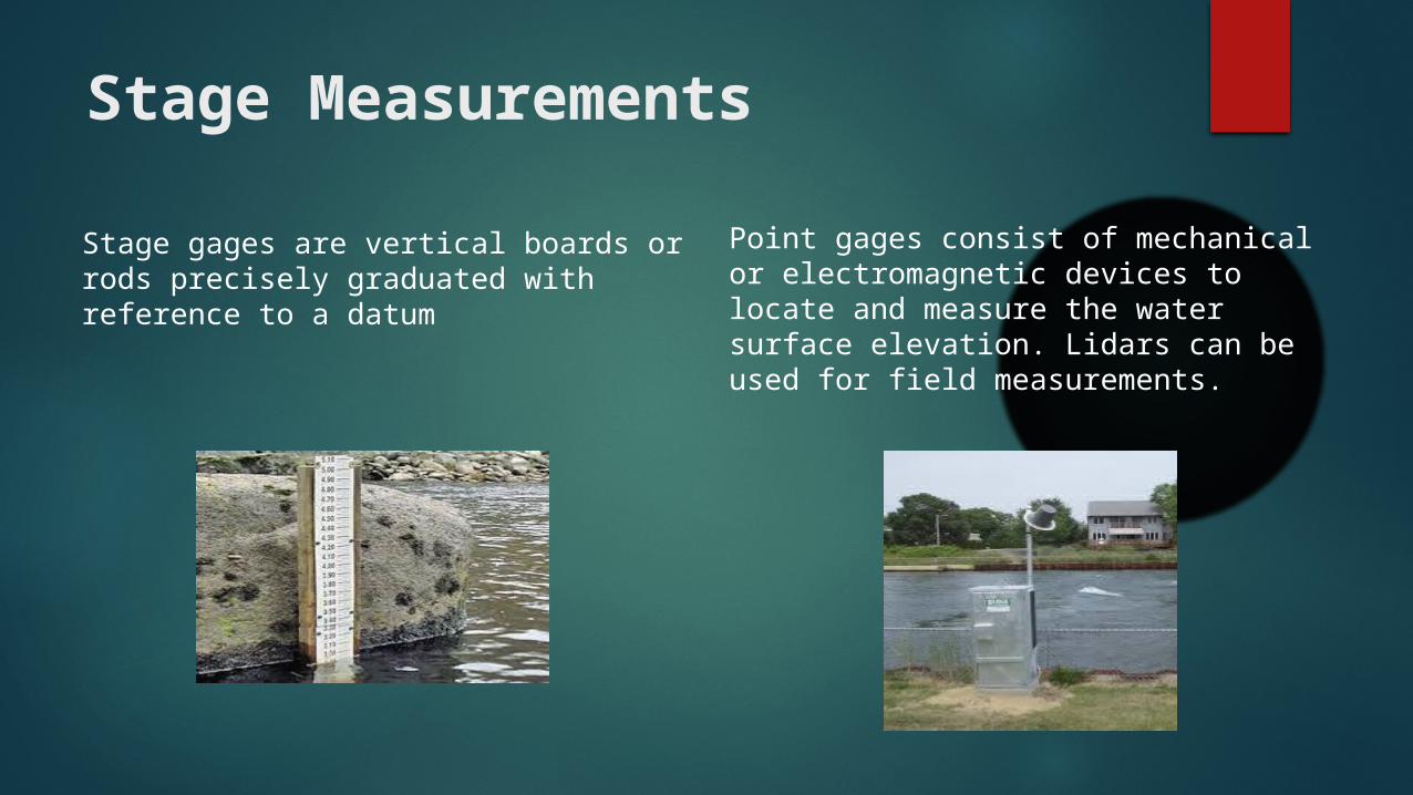
Stage gages are vertical boards or rods precisely graduated with reference to a datum
Point gages consist of mechanical or electromagnetic devices to locate and measure the water surface elevation. Lidars can be used for field measurements.
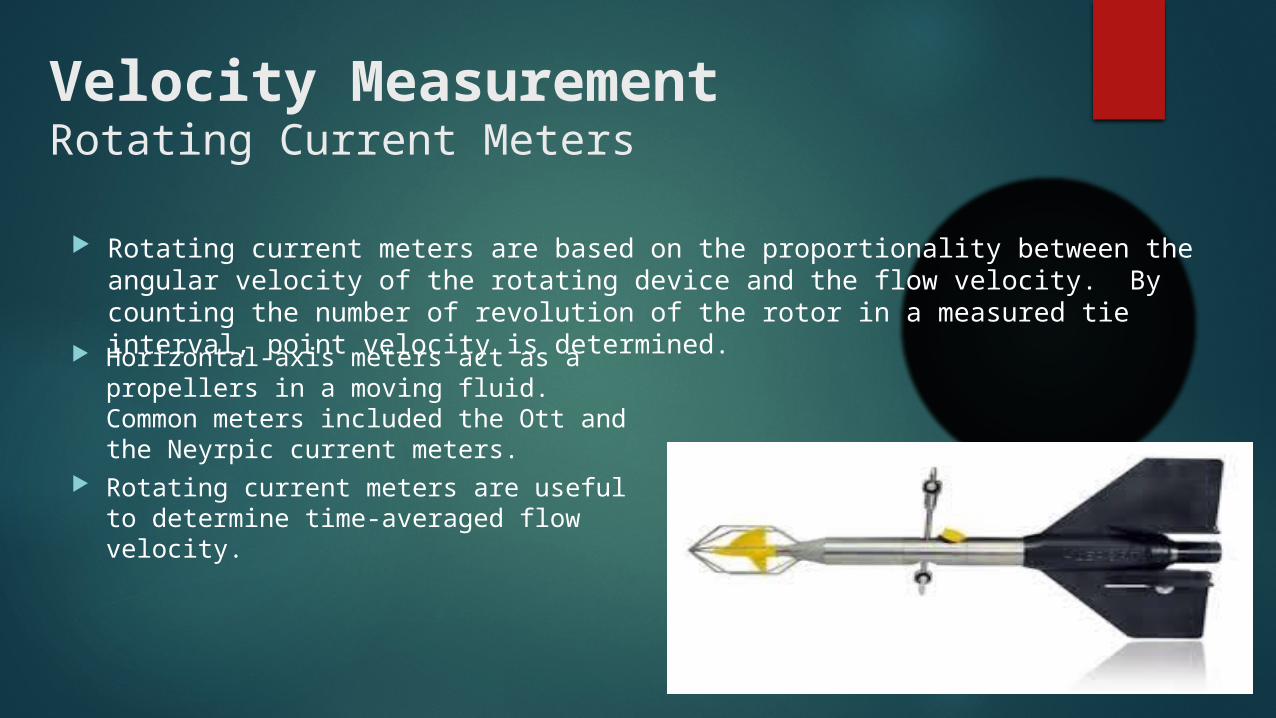
Velocity MeasurementRotating Current Meters
Horizontal-axis meters act as a propellers in a moving fluid. Common meters included the Ott and the Neyrpic current meters.
Rotating current meters are useful to determine time-averaged flow velocity.
Rotating current meters are based on the proportionality between the angular velocity of the rotating device and the flow velocity. By counting the number of revolution of the rotor in a measured tie interval, point velocity is determined.
The depth-averaged velocity is normally obtained from a time-averaged velocity profile. The following approximate methods for turbulent flows can be used to determine the depth-averaged flow velocity from point velocity measurements: The one point method (at 60% of the total depth measured down from the water
surface) uses the observed time-averaged velocity at 0.6 h as the mean velocity in the vertical. This method gives reliable results in uniform cross-sections.
The two point method (at 20% and 80% of the total depth measured down from the water surface) averages the two velocity measurements.
The three point method (at 20%, 60%, and 80% of the total depth measured down from the water surface) averages the one point and two point methods.
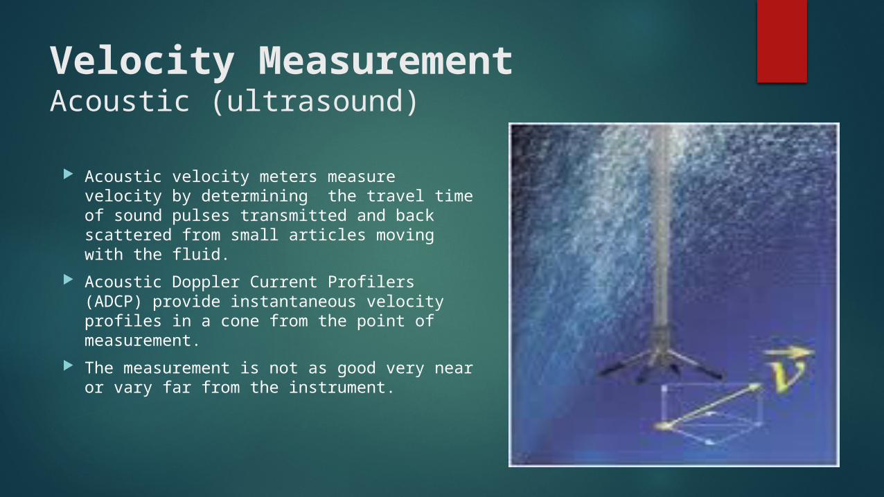
Velocity MeasurementAcoustic (ultrasound)
Acoustic velocity meters measure velocity by determining the travel time of sound pulses transmitted and back scattered from small articles moving with the fluid.
Acoustic Doppler Current Profilers (ADCP) provide instantaneous velocity profiles in a cone from the point of measurement.
The measurement is not as good very near or vary far from the instrument.

Velocity Measurements
Electromagnetic flow meters are based on Faraday’s induction law stating that voltage is induced by the motion of a conductor perpendicular to a magnetic field.
Hot film and hot wire anemometers are electrically heated sensors being cooled by advection. The heat loss being a function for the flow velocity, this laboratory instrument is calibrated to measure fluctuating velocities with high spatial resolution and high frequency response.

Cross Section Geometry
Cross-section geometry can be measured using a steel tape and rod and level.
The steel tape is used to measure the width of the channel.
The rod and level measured relative elevation. Measurements are taken at a tenth of the stream
length.

Bank Stability
Immediate results save the owner and engineer time and money, particularly with failed slopes
Measures the drained shear strength of soils in place
A new development allows for residual effective shear strength measurements
Used for designing earth slopes, retaining walls and determining the bearing capacity of foundations

River Measurement StrucutureDischarge Measurement
Type of discharge measurement structure: Weirs
Sharp-crested weir
Broad-crested weir
Flume Long-throated flume
Short-throated flume
Special flume
Source: http://www.usbr.gov/pmts/hydraulics_lab/pubs/wmm/chap07_13.html
River Measurement StrucutureDischarge Measurement
Main consideration to select a measuring structure: Accuracy requirements
Cost (construction, operation and maintenance)
Range of flow rates
Head loss
Ability to pass sediment
River Measurement StrucutureDischarge Measurement
Site selection consideration: To prevent excessive curvature of streamlines, channel reach
upstream should be relatively straight and uniform for a distance about 10 times average channel width
To ensure relatively smooth surface, Froude number upstream should be less than 0.5 for a distance of 30 yards
To prevent water surface fluctuation, the minimum distance from any upstream structure should be 20 times water surface width at maximum flow
Avoid placing structure in location where the soil characteristics are unsuitable.

WeirDischarge measurement
Sharp crested weir (when H1/l ≥ 15).
There are 2 condition: Free flow
Submerge flow, when the submergence (S) is bigger than critical factor (Sc). Thus Qsw should be multiplied by submergence factor (fs)
WeirDischarge measurement
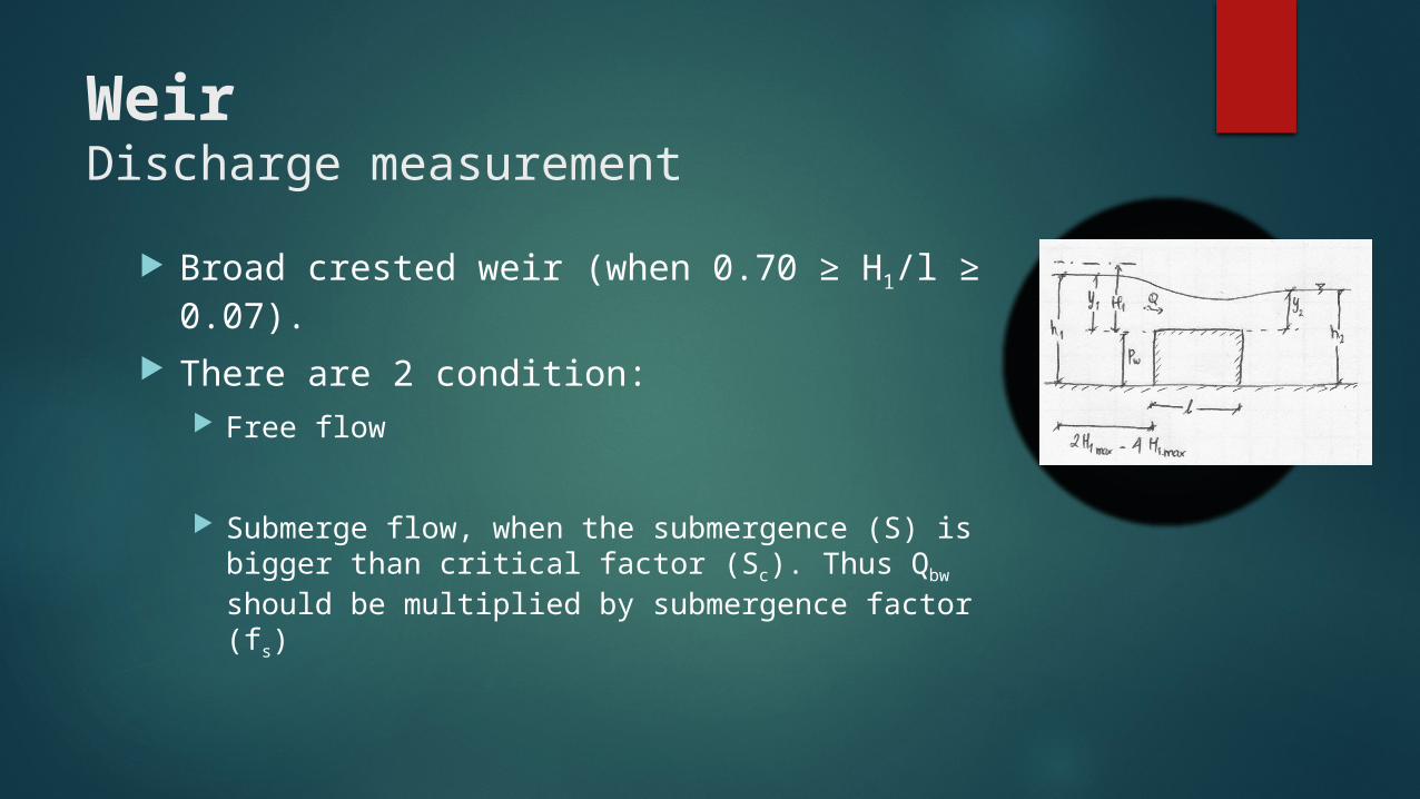
Broad crested weir (when 0.70 ≥ H1/l ≥ 0.07).
There are 2 condition: Free flow
Submerge flow, when the submergence (S) is bigger than critical factor (Sc). Thus Qbw should be multiplied by submergence factor (fs)
WeirDischarge measurement
Free flow is preferred than submerge flow, Submerge flow tends to be more inaccurate than free flow, because
submergence factor (fs) only predict the value of submerge flow.
Submerge flow needs 2 field data (y2 and y1)
Broad crested is preferred than sharp crested,
Because broad crested weir has a bigger critical submergence (Sc), so the probability of submerge flow in broad crested weir is less than in sharp crested weir
FlumeDischarge Measurement
Structure that cause a critical flow in a channel by either a width contraction or a combination of width and relatively small bottom contraction
Classes: Long-Throated Flumes
Short-Throated Flumes
Special Flumes
FlumeDischarge Measurement
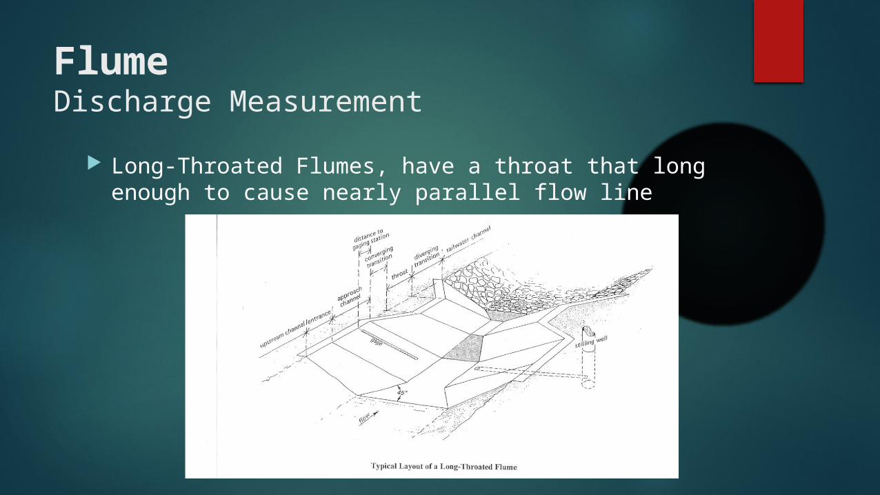
Long-Throated Flumes, have a throat that long enough to cause nearly parallel flow line
FlumeDischarge Measurement
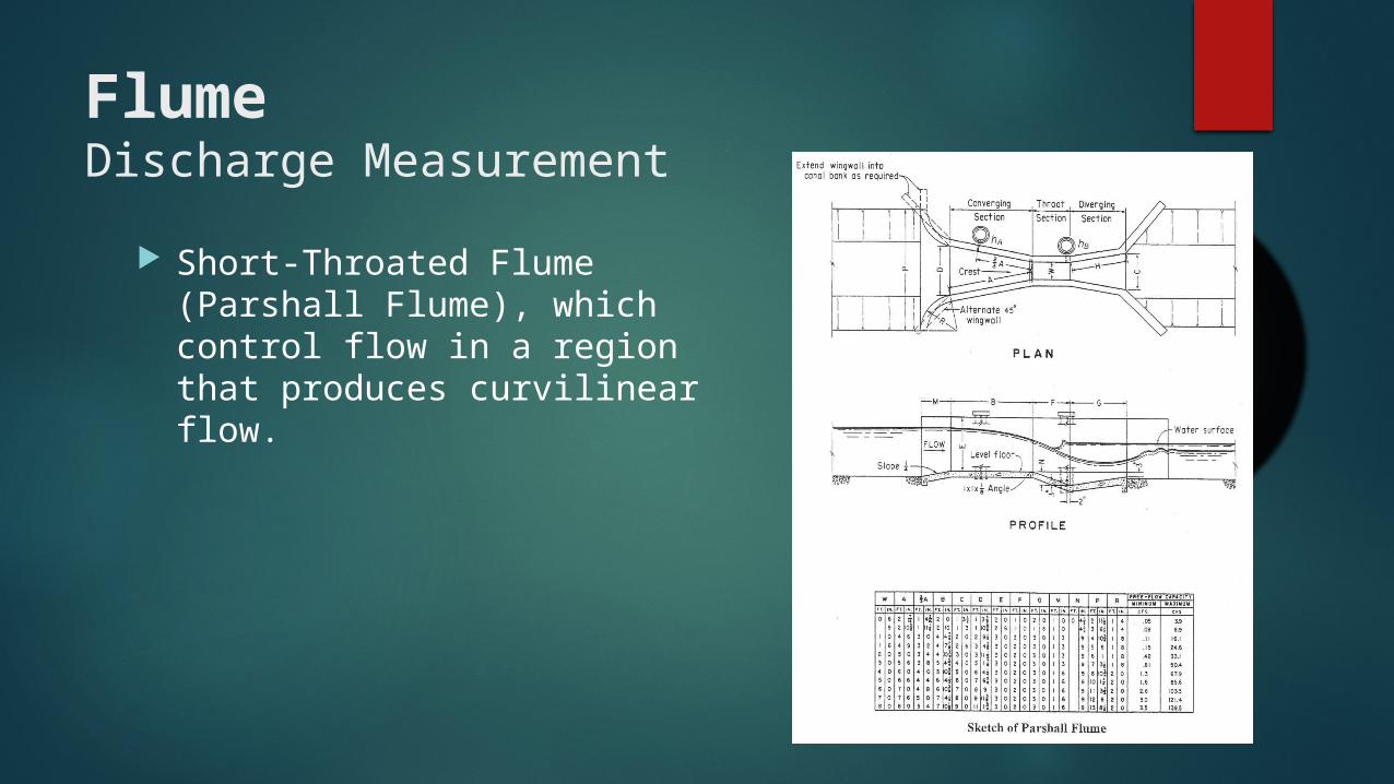
Short-Throated Flume (Parshall Flume), which control flow in a region that produces curvilinear flow.
FlumeDischarge Measurement
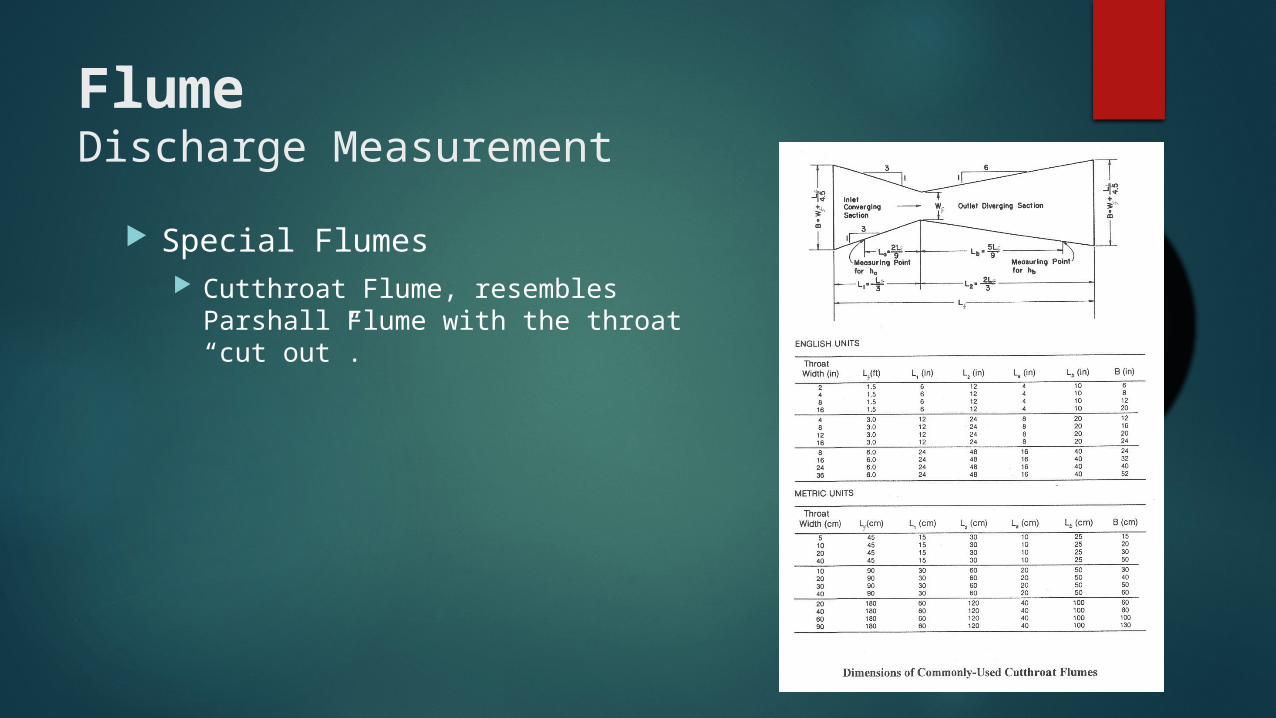
Special Flumes Cutthroat Flume, resembles Parshall
Flume with the throat “cut out”.
Auxiliary EquipmentDischarge measurement structures
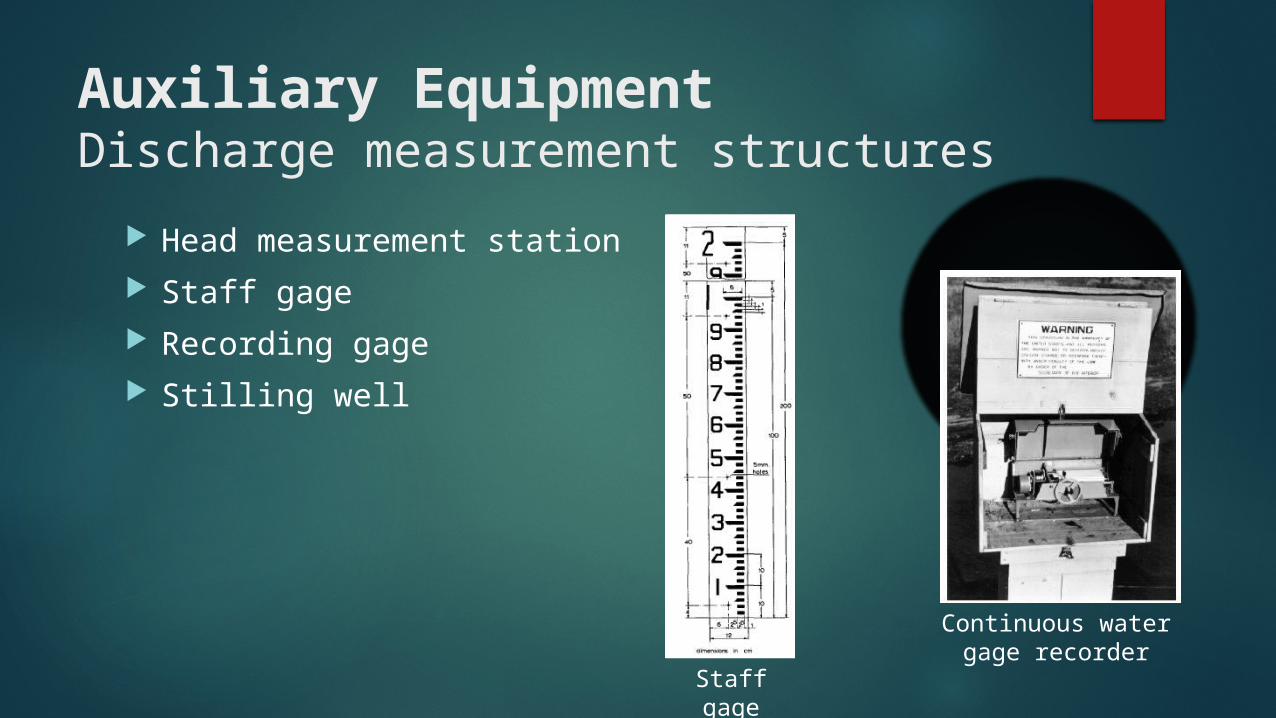
Head measurement station Staff gage Recording gage Stilling well
Staff gage
Continuous water gage recorder

Sampling Techniques for Sediment
Sampling the water-sediment mixture for Determine the mean suspended sediment concentration, Particle size distribution, Specific gravity, Temperature of the water sediment mixture, Other physical and chemical properties of the transported solids.
Sampling frequency Generally dictated by the study approach and level of funding
Types of sediment samplers: Bed Sediment Samplers. Suspended Sediment Samplers. Bed load samplers.

1. Bed sediment sampling
Shallow Samplers: Drag bucket samplers.
Scoop samplers.
Grab bucket or clamshell samplers.
Vertical pipe or core samplers.
Piston core samplers
Rotating bucket samplers.
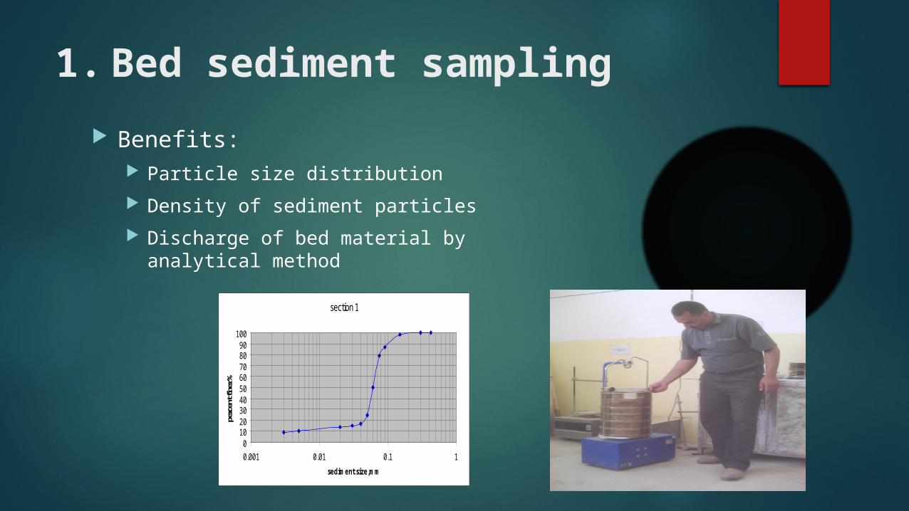
1. Bed sediment sampling
Benefits: Particle size distribution
Density of sediment particles
Discharge of bed material by analytical method
section 1
0102030405060708090
100
0.001 0.01 0.1 1
sediment size,mm
perc
ent f
iner
%
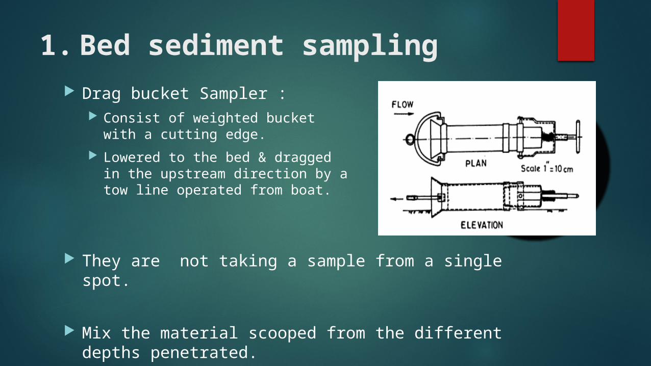
1. Bed sediment sampling Drag bucket Sampler :
Consist of weighted bucket with a cutting edge.
Lowered to the bed & dragged in the upstream direction by a tow line operated from boat.
They are not taking a sample from a single spot.
Mix the material scooped from the different depths penetrated.

1. Bed sediment sampling
Scoop Samplers: One end is closed.
Other end beveled to provide cutting edge.
Used up to 6 m depth.
Could collect samples from top 60 mm of the bed.
A hinged cover plate may be placed over the cutting edge of the sampler.
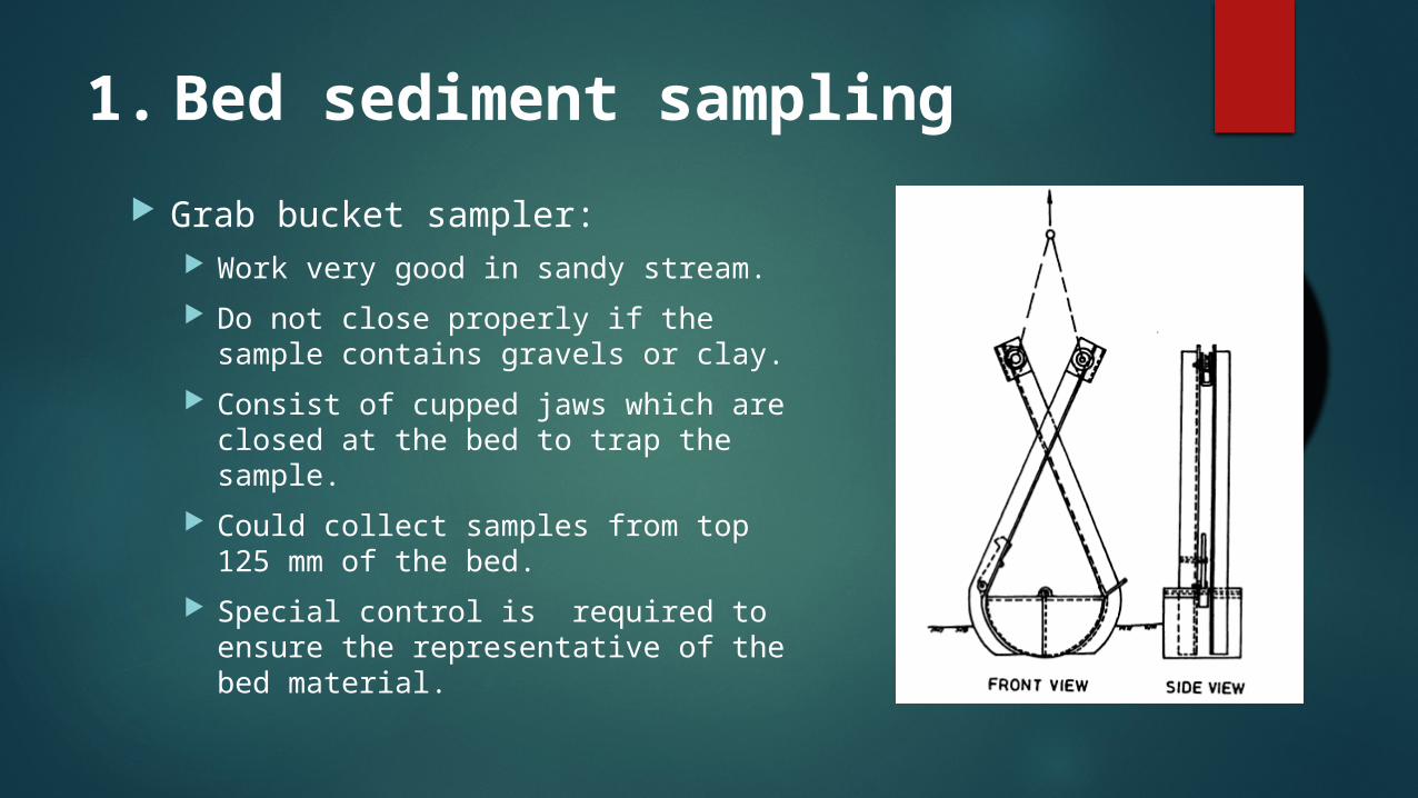
1. Bed sediment sampling
Grab bucket sampler: Work very good in sandy stream.
Do not close properly if the sample contains gravels or clay.
Consist of cupped jaws which are closed at the bed to trap the sample.
Could collect samples from top 125 mm of the bed.
Special control is required to ensure the representative of the bed material.

1. Bed sediment sampling Vertical pipe or core:
Consist of tube forced into the stream bed.
Good quality sample.
less disruptive than dredge or grab samplers.
Easy to use in fine grained bed but its hard to use in sand bed.
Inexpensive samples &simple to maintain.
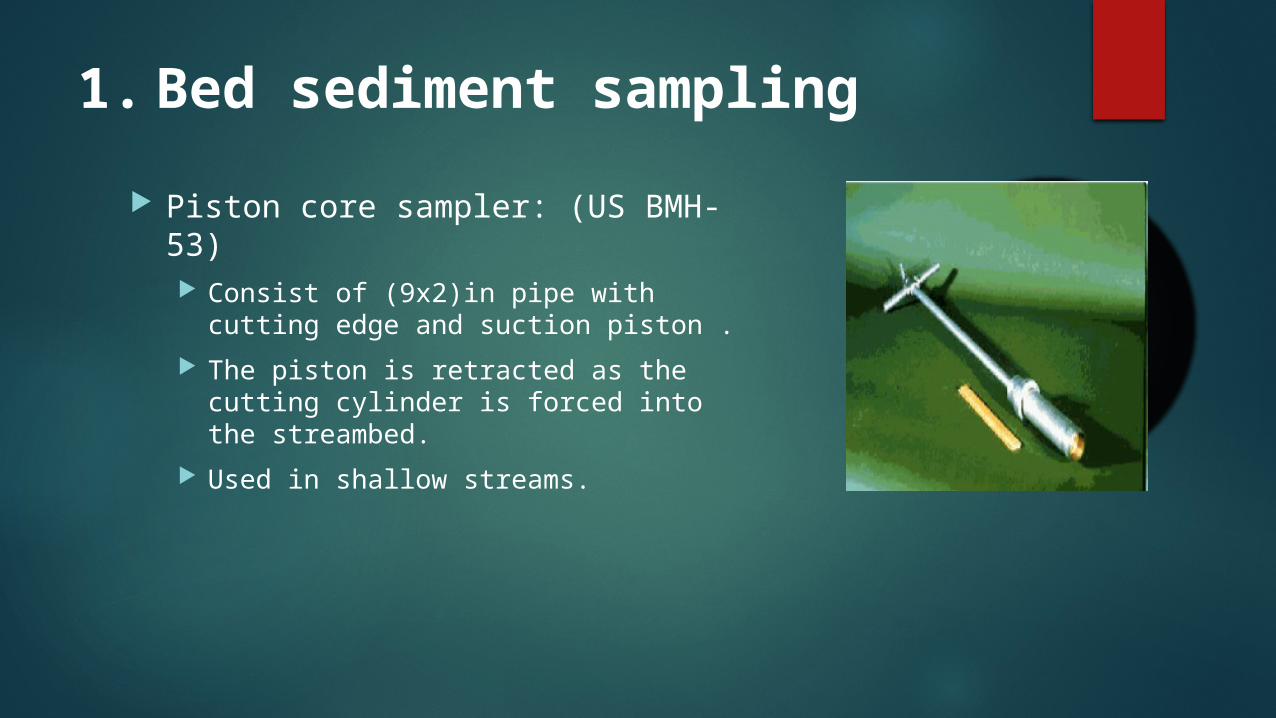
1. Bed sediment sampling
Piston core sampler: (US BMH-53) Consist of (9x2)in pipe with cutting
edge and suction piston .
The piston is retracted as the cutting cylinder is forced into the streambed.
Used in shallow streams.
1. Bed sediment sampling
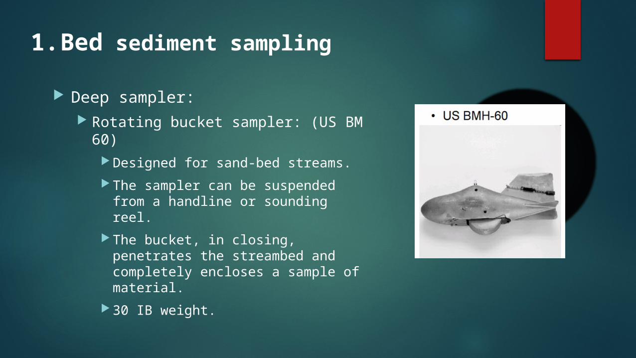
Deep sampler: Rotating bucket sampler: (US BM 60)
Designed for sand-bed streams.
The sampler can be suspended from a handline or sounding reel.
The bucket, in closing, penetrates the streambed and completely encloses a sample of material.
30 IB weight.

1. Bed sediment sampling
Deep sampler: Rotating bucket sampler: (US BM 54)
Designed to be suspended from a cable and to scoop up a sample of the bed sediment that is 3 in width and 2 in max depth.
When the sampler contacts the stream bed with the bucket completely retracted , the tension in the suspension cable is released & heavy coil spring quickly rotates the bucket through 180 degree to scoop up the sample.

1. Bed sediment sampling
Rotary-bucket bed material sampler: (US RBMH-80) hand-operated sampler that has a
semi-cylindrical bucket for collecting the bed material samples.
It is constructed from lightweight aluminum and uses a BM-54 sample bucket.
Operation is simple: the lever on the handle opens and closes the bucket.
2. Suspended Sediment Sampler
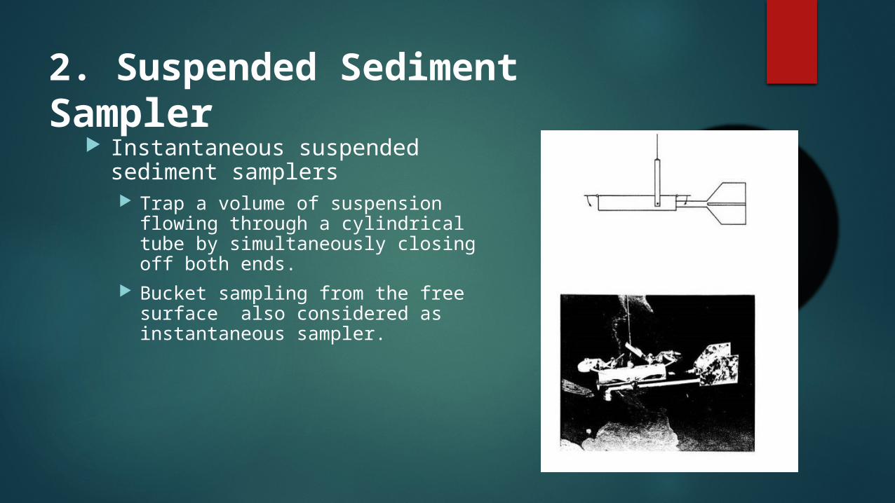
Instantaneous suspended sediment samplers Trap a volume of suspension flowing
through a cylindrical tube by simultaneously closing off both ends.
Bucket sampling from the free surface also considered as instantaneous sampler.
2. Suspended Sediment Sampler
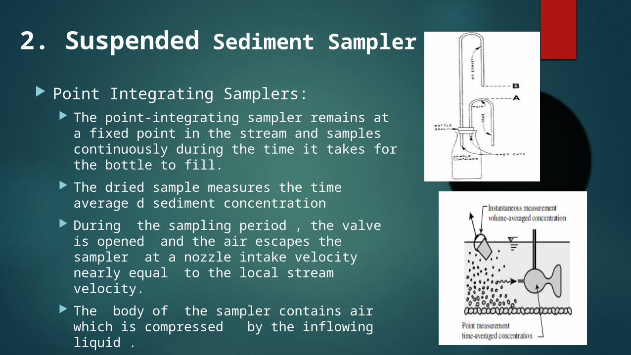
Point Integrating Samplers: The point-integrating sampler remains at a fixed
point in the stream and samples continuously during the time it takes for the bottle to fill.
The dried sample measures the time average d sediment concentration
During the sampling period , the valve is opened and the air escapes the sampler at a nozzle intake velocity nearly equal to the local stream velocity.
The body of the sampler contains air which is compressed by the inflowing liquid .
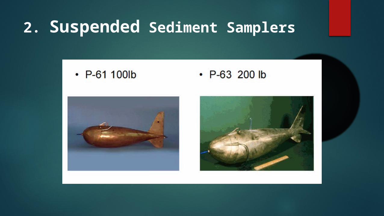
2. Suspended Sediment Samplers
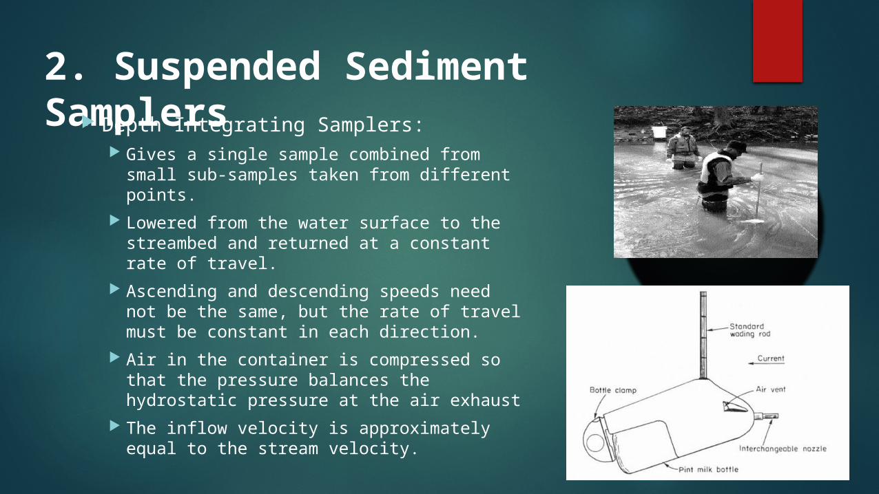
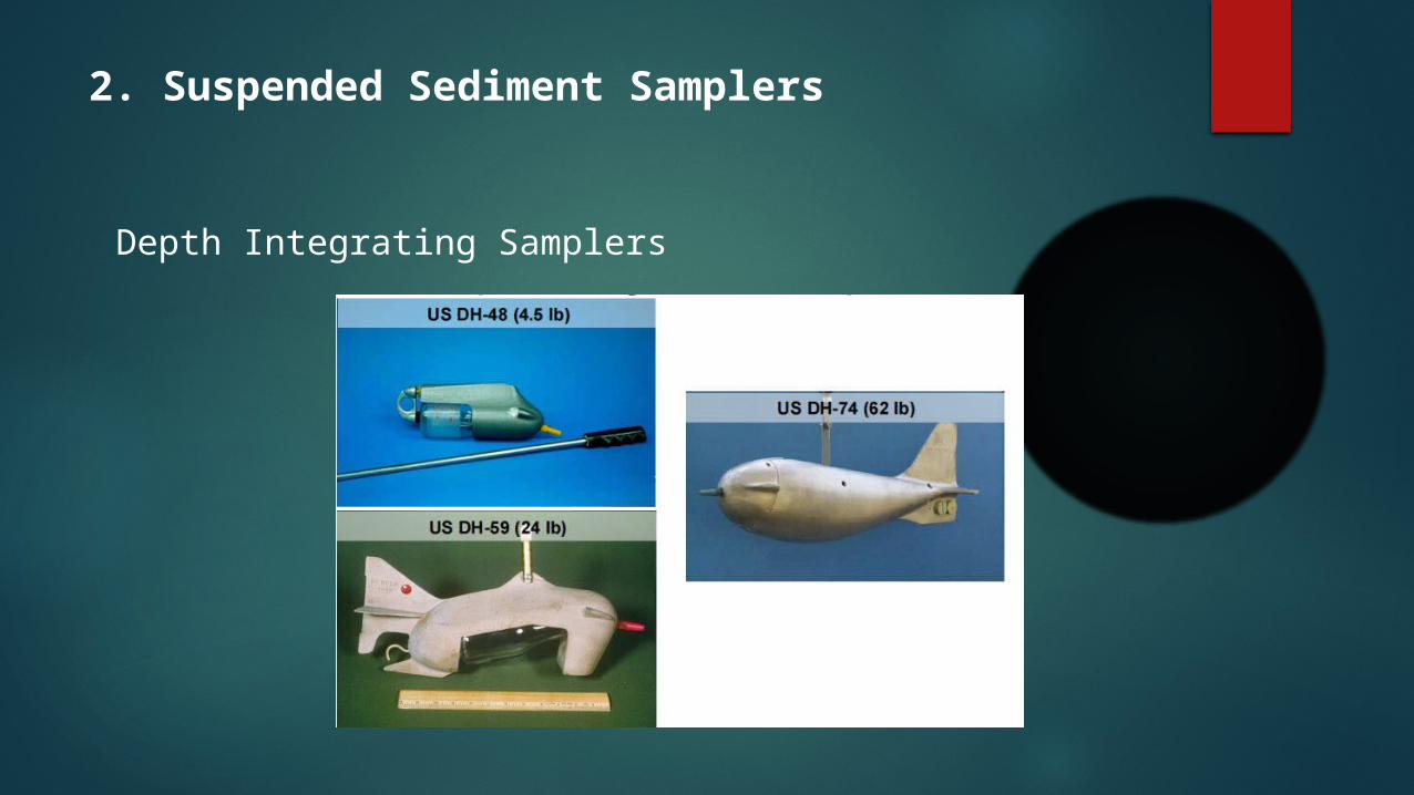
2. Suspended Sediment Samplers Depth Integrating Samplers:
Gives a single sample combined from small sub-samples taken from different points.
Lowered from the water surface to the streambed and returned at a constant rate of travel.
Ascending and descending speeds need not be the same, but the rate of travel must be constant in each direction.
Air in the container is compressed so that the pressure balances the hydrostatic pressure at the air exhaust
The inflow velocity is approximately equal to the stream velocity.
2. Suspended Sediment Samplers
Depth Integrating Samplers
3. Bed load Measurements
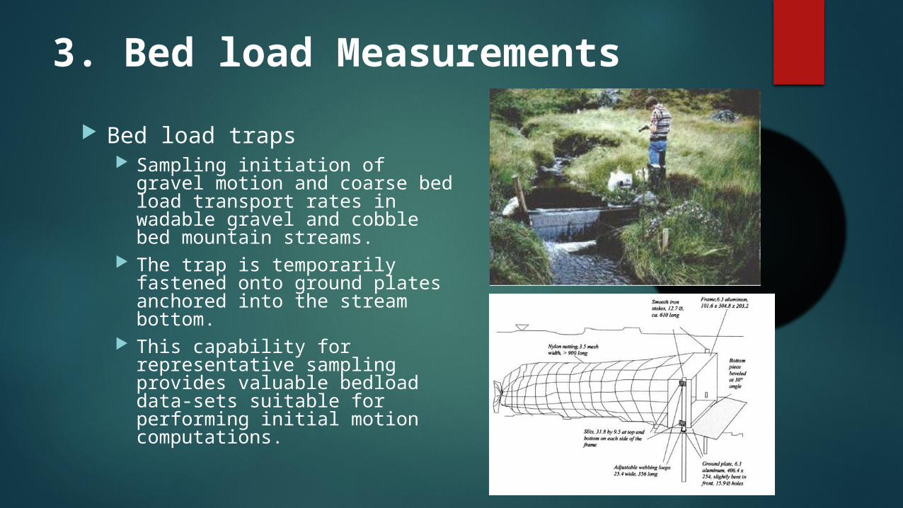
Bed load traps Sampling initiation of gravel
motion and coarse bed load transport rates in wadable gravel and cobble bed mountain streams.
The trap is temporarily fastened onto ground plates anchored into the stream bottom.
This capability for representative sampling provides valuable bedload data-sets suitable for performing initial motion computations.
3. Bed load Measurements
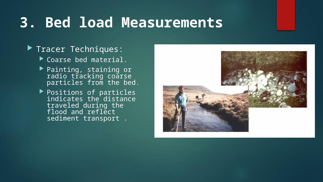
Tracer Techniques: Coarse bed material. Painting, staining or radio
tracking coarse particles from the bed.
Positions of particles indicates the distance traveled during the flood and reflect sediment transport .

3. Bed load Measurements
Haley-Smith sampler: Suited to coarse sand to fine gravel
bed streams. Long period of sampling could clog
the sample bag. Very coarse material(ds>80 mm)
will not enter the sampler & very fine material(ds<0.5 mm) will be washed.

References
Geol 642. Fluvial Geomorphology – Field Trip Manual. Julien P. Y., (2010). Erosion and Sedimentation. Cambridge
University Press, Cambridge, UK. http://www.rickly.com/index.htm U.S. Bureau of Reclamation, (2001). Water Measurement
Manual. U.S. Government Printing Office, Washington, DC.
Voltman W. F., (1989). Discharge Measurement Structures 3rd ed. International Institute for Land Reclamation and Improvement, Wageningen, The Netherlands.