research on kinematics analysis of spherical single-cone
TRANSCRIPT

Research on kinematics analysis of spherical single-cone PDCcompound bit and rock breaking simulation verificationChunyan Kong1,*, Rongjun Zhu1, Derong Zhang2, and Shuangshuang Li1
1 School of Mechanical Engineering, Xihua University, Chengdu, Sichuan 610039, PR China2 School of Mechatronic Engineering, Southwest Petroleum University, Chengdu, Sichuan 610500, PR China
Received: 16 April 2021 / Accepted: 2 June 2021
Abstract. The single-cone bit has become the first choice for slim hole sidetracking and deep well drilling withits unique rock breaking method and high ROP (Rate Of Penetration), with its main failure mode being of earlyexcessive wear of the cutting teeth. In order to improve the adaptability of single-cone bits to hard and highlyabrasive formations, a spherical single-cone Polycrystalline Diamond Compact (PDC) compound bit isdesigned. According to the characteristics of the tooth profile, the way of tooth arrangement and the way ofcontact between the cutting teeth and the rock, the acceleration equation to the cutting teeth of the sphericalsingle-cone PDC compound bit is established. The acceleration of the single-cone bit is verified by numericalsimulation experiment of rock-breaking. The shaft inclination angle of the cone, the position and height ofthe PDC teeth, the radius of the PDC teeth, the lateral rotation angle and the front inclination angle onthe acceleration are studied. The results show that as the shaft inclination angle increases, the bit transmissionratio gradually increases, and the harder the rock formation, the larger the transmission ratio of the single-conebit; the shaft inclination angle and the position of the PDC tooth have a greater influence on the acceleration ofthe PDC tooth, and the radius, lateral rotation angle and front inclination angle of the PDC tooth have a smallinfluence on the acceleration of the PDC tooth; rock properties have an impact on the acceleration of the cut-ting teeth, with the acceleration of the cutting teeth in hard rock formations being higher than that in soft rockformations; near the top of the cone, the absolute acceleration of the cutting teeth will fluctuate sharply andcause severe wear of the cutting teeth, so the tooth distribution in this area should be strengthened; on thepremise that the bearing life of the single-cone bit is allowed, the value of the shaft inclination angle b canbe approached to 70�. The relative error between the theoretical analysis results of the acceleration of thePDC cutter and the rock-breaking simulation experiment results is between �0.95% and �2.24%. This researchlays a theoretical foundation for the dynamic research of spherical single-cone PDC compound bit.
Nomenclature
q Radius vector, as shown in Figure 6, mm;h Polar angle, degree;Z Vertical height, mm;L Distance from the center of the cone to the back
cone plane of the cone, mm;hC Position height of the center point C of the
PDC cutting tooth surface, mm;rC Radius of the characteristic circle where point
C is located, mm;a Rotation angle of the cone relative to the cone
shaft, degree;
a0 Initial rotation angle of the cone relative to thecone shaft, degree;
x1, y1, z1 Coordinate value of point Q in the coordinatesystem O1X1Y1Z1, mm;
rQ Radius of PDC cutter, mm;b Shaft inclination angle of single-cone bit,
degree;h Position angle of the drill bit within 0 ~ t, the
position change caused by the rotation of thedrill bit, degree;
h0 Extreme position angle of the origin O0 of themoving coordinate system, degree;
ZO0 Vertical height of the moving coordinate originO0, mm;
d Front inclination angle of PDC cutter, degree;g Lateral rotation angle of PDC cutter, degree;* Corresponding author: [email protected]
This is an Open Access article distributed under the terms of the Creative Commons Attribution License (https://creativecommons.org/licenses/by/4.0),which permits unrestricted use, distribution, and reproduction in any medium, provided the original work is properly cited.
Oil & Gas Science and Technology – Rev. IFP Energies nouvelles 76, 52 (2021) Available online at:�C. Kong et al., published by IFP Energies nouvelles, 2021 ogst.ifpenergiesnouvelles.fr
https://doi.org/10.2516/ogst/2021034
REGULAR ARTICLEREGULAR ARTICLE

c Angle between the baseline of the PDC toothand the axis of the drill bit, degree;
r0 Uniaxial compressive strength of limestone, andr0 = 124 MPa;
r Uniaxial compressive strength of any rock,MPa.
1 Introduction
The main drill bits currently used in drilling engineering arePDC bits and tri-cone bits. The single-cone bit is a cuttingtype drill bit between the tri-cone bit and the PolycrystallineDiamond Compact (PDC) bit [1], and the cutting teeth onthe cone crush the rock by rolling, scraping, and twisting.With its unique rock-breaking method and high ROP (RateOf Penetration), it has won the favor of the drilling industryand has become the preferred drill bit for slim hole sidetrack-ing and deep well drilling [2–6]. Although the single-cone bitis a good choice for slim hole drilling because of its good for-mation adaptability, strong guiding ability and easy to besmall-sized [1, 7], according to the field application trackinginvestigation and statistical analysis, the single-cone bit alsohas a fatal weakness, that is, the wear resistance of the cut-ters is seriously insufficient [1, 8, 9]. The spherical single-conebits currently used in the oil field (Fig. 1) all use cementedcarbide inserts (such as cone button teeth, wedge teeth,etc.), which can only be used in soft formations; For hardformations with high abrasiveness, the early wear is severeand the life span is short [10, 11]. This is because the sin-gle-cone bit will produce relatively large slip at the bottomof the well when it is working (Fig. 2), resulting in severewear of the carbide cutting teeth. Therefore, the wear resis-tance of the cutting teeth will directly determine the work-ing life of the single-cone bit. Once the cutters are dull, thedrilling speed will decrease sharply. The main reason whythe single-cone bit is less and less used is that the teeth arenot wear-resistant, which leads to the ROP decline andshort service life of the bit. It is of great practical significanceand development prospect to research and design single-cone bits with strong abrasion resistance and wider litholog-ical adaptability [12, 13].
Ma [14] founded the geometry and kinematics of modernroller cone bits. Wang et al. [15] and others [16] designed aspecial-shaped single-cone bit to increase the working life ofthe bit, but the special-shaped single-cone bit is not a full-hole drill, and the rock-breaking efficiency is still not high.Li [17] researched and designed a new type of impactpress-in single-cone bit. After field application, it was foundthat the bit was worn seriously. Yu and Ding [18], Yu [19]and Deng et al. [20] studied the geometry, kinematics, anddynamics of the spherical single-cone bit, and discussed thedesign method of the tooth surface structure of the single-cone bit. Yu et al. [7] studied the influence of differentgeometric parameters and motion parameters for sphericalsingle-cone bits on rock-breaking. However, many single-cone bit researchers have not conducted in-depth anddetailed studies on the acceleration of PDC cutting teethfor the special motion trajectory of single-cone bits.
In recent years, researchers have done a lot of research onbit technology. New bit technology is emerging, especiallythe improvement of bit performance brought by new bitstructures. Baker Hughes Company has developed a newhybrid bit product by combining fixed PDC and unfixedcone. The special structure enables the bit to achieve gooddrilling results in some special formations and drillingrequirements [21–25]. Smith bits of Schlumberger hassuccessively launched 360� rotary PDC bit [26, 27] andconical diamond element Bits [28–30]. These two kinds ofbit have good performance in some special difficult to drillformation. Chen et al. proposed a new technology ofsingle-cone bit, which is composed of fixed and unfixed[31]. The research team led by Professor Yang of SouthwestPetroleum University proposed a diamond bit with unfixedcutting structure through structural innovation [32, 33],and many useful research results have been obtained[34–36]. Compared with the existing cone bit and PDCbit, the new bit has obvious advantages in rock breakingefficiency and service life. The bit is expected to form anefficient rock breaking tool in the near future. The structureof the bit has a decisive influence on the adaptability andperformance of the bit. With the structural innovation,new research on new drill bits and new tools will have newbreakthroughs [37]. Sometimes, the new bit structure can
Fig. 1. Failed single-cone bit (a) worn cutting teeth (b) brokencutting teeth.
Fig. 2. Bottom hole pattern of single-cone bit.
C. Kong et al.: Oil & Gas Science and Technology – Rev. IFP Energies nouvelles 76, 52 (2021)2

play a role of surprise and drive the development of drillingtechnology.
In order to overcome the shortcomings of the prior art(Fig. 1), improve the wear resistance of the single-cone bitand prolong the service life of the bit, based on an in-depthanalysis of the structural characteristics and working prin-ciples of the single-cone bit, this paper adopts the designconcept of the spherical single-cone bit + PDC bit andthe principle that the PDC cutting teeth work slowly andalternately on the cone, with the design concept of sphericalsingle-cone PDC compound bit proposed (Fig. 3). In orderto make this new type of bit better serve the needs of oildrilling production, we need to conduct an in-depth studyon the kinematics and related parameters for the PDC teethon the single-cone bit. However, due to the changes in thetooth profile characteristics and tooth arrangement methodfor the new drill bit, the characteristic points on the PDCcutting tooth edge can no longer be simplified to any pointon the cone sphere. Moreover, PDC teeth have cuttingangles such as front inclination angle and lateral rotationangles during the rock-breaking process. It is necessary tore-establish the kinematics equations of the cutting teethof the spherical single-cone PDC compound bit to thor-oughly grasp the acceleration characteristics of the newtype of bit, which provides basic support and reference forthe dynamic research, subsequent design, developmentand application of this kind of bit.
2 Establishment coordinate system
As shown in Figure 4, when the spherical single-cone PDCcompound bit is working, the movement of the coneincludes the revolution of the bit body and cone aroundthe center line of the bit, the movement along the directionof the center line of the bit, and the rotation of the conearound the cone axis. Any studies on the basic motions ofcutters on cone shall be based on deep understanding ofthe features of bit in the coordinate system, basic planeand structure.
2.1 Static cylindrical coordinate system
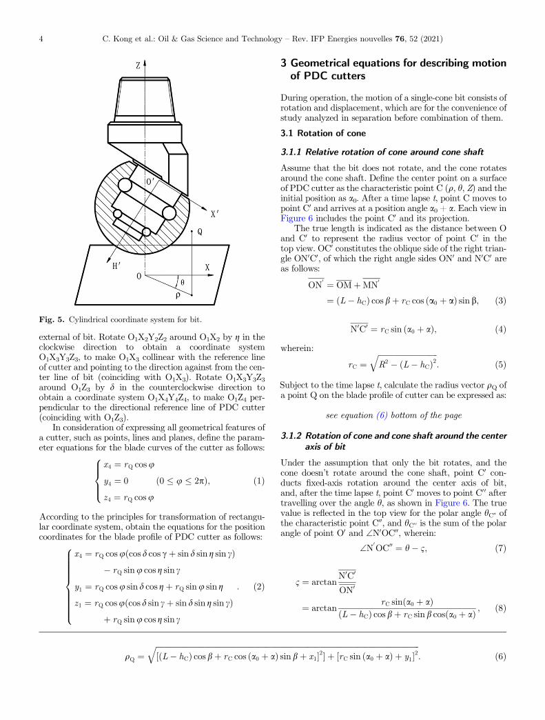
Use the central axis of a single-cone bit as the coordinateaxis OZ to establish a static/fixed cylindrical coordinate
system (static coordinate system) [20], set the polar axison a horizontal reference plane and in a certain direction.Thereafter, a point Q within the space can be representedby Q (q, h, Z), as shown in Figure 5.
2.2 Dynamic cylindrical coordinate system
Set up a dynamic cylindrical coordinate system for a single-cone [19], with the origin O0 set at the bottom center pointof cone, the vertical axis O0H0 coinciding with the axis ofcone, and polar axes O0X0 and O0H0 perpendicular with eachother. The plane defined by H0O0X0 is called as a polar axisplane of cone.
Figure 6 shows the projection relationships of a complexcylindrical coordinate system, including: (a) view fromdirection A for the back cone plane of cone; (b) front viewof single-cone; and (c) top view in addition to (b). Figure 6indicates the parameters for bit structure as (L, R, b),parameters for bit and cone positions as (h0, ZO0, a0),parameters for PDC cutter’s position on cone as (hC, rC,c, d, g), and parameters of point Q’s position on PDC cutterblade profile as (rQ, u).
Set up four rectangular coordinate systems for PDC cut-ters and respectively from the center points of four cutters[38]. Set up a coordinate system O1X1Y1Z1 for the positionof PDC cutters, to make O1Z1//OZ and pointing to thesame direction as OZ, and O1X1 in a horizontal directionand perpendicular to OZ. Rotate O1X1Y1Z1 around O1Y1by an angle c (the included angle between the reference lineof cutter and the axis of bit) in the clockwise direction toobtain a coordinate system O1X2Y2Z2, to make O1X2 colli-near with the reference line of cutter and pointing to the
Fig. 3. Spherical single-cone PDC compound bit.
Fig. 4. The motion of spherical single-cone PDC compound bit.
C. Kong et al.: Oil & Gas Science and Technology – Rev. IFP Energies nouvelles 76, 52 (2021) 3
external of bit. Rotate O1X2Y2Z2 around O1X2 by g in theclockwise direction to obtain a coordinate systemO1X3Y3Z3, to make O1X3 collinear with the reference lineof cutter and pointing to the direction against from the cen-ter line of bit (coinciding with O1X3). Rotate O1X3Y3Z3around O1Z3 by d in the counterclockwise direction toobtain a coordinate system O1X4Y4Z4, to make O1Z4 per-pendicular to the directional reference line of PDC cutter(coinciding with O1Z3).
In consideration of expressing all geometrical features ofa cutter, such as points, lines and planes, define the param-eter equations for the blade curves of the cutter as follows:
x4 ¼ rQ cosu
y4 ¼ 0
z4 ¼ rQ cosu
8>><>>:
0 � u � 2pð Þ; ð1Þ
According to the principles for transformation of rectangu-lar coordinate system, obtain the equations for the positioncoordinates for the blade profile of PDC cutter as follows:
x4 ¼ rQ cosu cos d cos cþ sin d sin g sin cð Þ� rQ sinu cos g sin c
y1 ¼ rQ cosu sin d cos gþ rQ sinu sin g
z1 ¼ rQ cosu cos d sin cþ sin d sin g sin cð Þþ rQ sinu cos g sin c
8>>>>>>>><>>>>>>>>:
: ð2Þ
3 Geometrical equations for describing motionof PDC cutters
During operation, the motion of a single-cone bit consists ofrotation and displacement, which are for the convenience ofstudy analyzed in separation before combination of them.
3.1 Rotation of cone
3.1.1 Relative rotation of cone around cone shaft
Assume that the bit does not rotate, and the cone rotatesaround the cone shaft. Define the center point on a surfaceof PDC cutter as the characteristic point C (q, h, Z) and theinitial position as a0. After a time lapse t, point C moves topoint C0 and arrives at a position angle a0 + a. Each view inFigure 6 includes the point C0 and its projection.
The true length is indicated as the distance between Oand C0 to represent the radius vector of point C0 in thetop view. OC0 constitutes the oblique side of the right trian-gle ON0C0, of which the right angle sides ON0 and N0C0 areas follows:
ON0 ¼ OMþMN
0
¼ L� hCð Þ cos bþ rC cos a0 þ að Þ sin b; ð3Þ
N0C0 ¼ rC sin a0 þ að Þ; ð4Þwherein:
rC ¼ffiffiffiffiffiffiffiffiffiffiffiffiffiffiffiffiffiffiffiffiffiffiffiffiffiffiffiffiffiffiffiR2 � L� hCð Þ2
q: ð5Þ
Subject to the time lapse t, calculate the radius vector qQ ofa point Q on the blade profile of cutter can be expressed as:
see equation (6) bottom of the page
3.1.2 Rotation of cone and cone shaft around the centeraxis of bit
Under the assumption that only the bit rotates, and thecone doesn’t rotate around the cone shaft, point C0 con-ducts fixed-axis rotation around the center axis of bit,and, after the time lapse t, point C0 moves to point C00 aftertravelling over the angle h, as shown in Figure 6. The truevalue is reflected in the top view for the polar angle hC00 ofthe characteristic point C00, and hC0 0 is the sum of the polarangle of point O0 and \N0OC00, wherein:
\N0OC00 ¼ h� 1; ð7Þ
1 ¼ arctanN0C0
ON0
¼ arctanrC sinða0 þ aÞ
L� hCð Þ cos bþ rC sin b cosða0 þ aÞ ; ð8Þ
qQ ¼ffiffiffiffiffiffiffiffiffiffiffiffiffiffiffiffiffiffiffiffiffiffiffiffiffiffiffiffiffiffiffiffiffiffiffiffiffiffiffiffiffiffiffiffiffiffiffiffiffiffiffiffiffiffiffiffiffiffiffiffiffiffiffiffiffiffiffiffiffiffiffiffiffiffiffiffiffiffiffiffiffiffiffiffiffiffiffiffiffiffiffiffiffiffiffiffiffiffiffiffiffiffiffiffiffiffiffiffiffiffiffiffiffiffiffiffiffiffiffiffiffiffiffiffiffiffiffiffiffiffiffiffiffiffiffiffiffiffiL� hCð Þ cos bþ rC cos a0 þ að Þ sin bþ x1½ �2� þ rC sin a0 þ að Þ þ y1½ �2
q: ð6Þ
Fig. 5. Cylindrical coordinate system for bit.
C. Kong et al.: Oil & Gas Science and Technology – Rev. IFP Energies nouvelles 76, 52 (2021)4

Accordingly, subject to the time lapse t, calculate the polarangle hQ of a point Q on the blade profile of cutter can beexpressed as:
hQ ¼ h0 þ h
� arctanrC sinða0 þ aÞ þ y1
L� hCð Þ cos bþ rC sin b cosða0 þ aÞ þ x1:
ð9Þ
3.2 Displacement of cone
During operation, the cone moves along the center axis ofbit in addition to rotation. The true length is reflected inFigure 6b for the net vertical height ZC0 of the characteristic
point C after the time t. Accordingly, subject to the timelapse t, calculate the vertical height ZQ of a point Q onthe blade profile of cutter can be expressed as:
ZQ ¼ zO � rC cos a0 þ að Þ sin b� hC sin bþ z1: ð10ÞEquations (6), (9) and (10) are kinematic geometricequations of the spherical single-cone PDC compound bit.
4 Acceleration equation of PDC toothon single-cone
In order to facilitate the study of the acceleration of thePDC teeth on the cone, the rotation and movement ofthe cone are studied separately and combined.
Fig. 6. Geometry of spherical single-cone PDC compound bit.
C. Kong et al.: Oil & Gas Science and Technology – Rev. IFP Energies nouvelles 76, 52 (2021) 5

The angular velocity of the bit body is x1, and the angu-lar acceleration is e1.
e1 ¼ dx1
dt¼ d2h
dt2; ð11Þ
The angular velocity of the cone around the cone axis is x2,and its angular acceleration is e2.
e2 ¼ dx2
dt¼ d2a
dt2; ð12Þ
The up and down position of the bit body is ZO0, and theacceleration is aZ
aZ ¼ d2ZO0
dt2; ð13Þ
e1, e2 and aZ are all random variables, and through exper-imental measurements, it can be seen how their instanta-neous real values change with time.
The acceleration of a characteristic point on a single-cone PDC tooth, especially the acceleration when thecutting tooth impacts with the bottom of the hole, is animportant parameter for rock-breaking and cutting toothstrength. However, the actual measurement of the accelera-tion and dynamic load of the cutting teeth is very trouble-some and cannot be implemented on a large scale. It isobviously very useful if the mathematical relationshipbetween the acceleration of the PDC teeth of the single-cone bit and the above-mentioned measurable bit accelera-tion e1, e2 and aZ can be established.
In order to facilitate the study of the acceleration of thesingle-cone bit of the PDC tooth, the absolute movement ofa certain characteristic point on the single-cone PDC toothis regarded as the combination of the following three kindsof movements. That is, for the longitudinal implicatedmotion of point Q, its position variable is ZQ, and its accel-eration is aQZ
; for the tangentially implicated movement ofpoint Q, its position variable is the polar angle hQ, and theacceleration is aQs; for the radial relative movement of pointQ, the position variable is the vector radius qQ, and theacceleration is aQq; the three moving directions are 90� witheach other. Starting from the geometrical equation ofmotion of the single-cone bit, the acceleration equation ofany point on the PDC tooth is established.
(1) Relative acceleration arThe acceleration caused by the radial movement is
the relative acceleration, with the relative accelerationbeing the derivative of the radial velocity with respect totime t.
Let
A ¼ L� hCð Þ cos b; ð14Þ
B ¼ rC sin b; ð15Þ
C ¼ RQ cosu cos d cos cþ cosu sin g sin c� sinu cos g sin cð Þ;ð16Þ
D ¼ rQ cosu sin d cos gþ sinu sin gð Þ; ð17Þ
kCq ¼1
2qQrC cos2 b sin 2ða0 þ aÞ
� L� hCð Þ sin 2b sin a0 þ að Þ; ð18Þ
kCq ¼1qQ
cos a0 þ að Þðcosu sin d cosg
þ sinu singÞ� sin b sin a0 þ að Þðcosu cos d sin c
þ cosu sinu sing cos c� sinu cos g cos cÞ
26664
37775:
ð19ÞThen there is
ar ¼ d2qQdt2
¼ 1qQ
ðr2C � B2Þ cos 2 a0 þ að Þ � B cos a0 þ að Þ�Aþ Cð Þ� �DrC sinða0 þ aÞ�x2
2 þ1qQ
�f rC � cos2 b sin a0 þ að Þ þ D� �
rC cosða0
þ aÞ� Aþ Cð Þge2 � 1qQ
kCq þ kQqrQ
� �2r2Cx
22; ð20Þ
(2) Tangentially implicated acceleration aesLet
m ¼ A cos a0 þ að Þ þ B þ C cos a0 þ að Þ þD sinb sin a0 þ að ÞAþ B cos a0 þ að Þ þ C½ �2 þ rC sin a0 þ að Þ þD½ �2 ;
ð21Þ
dmda
¼ D sin b cos a0 þ að Þ � sin cos a0 þ að ÞðAþ CÞq2Q
Aþ Cð Þ cos a0 þ að Þ þ B þ D sin b sin a0 þ að Þ½ �� 2 Aþ B cos a0 þ að Þ þ C½ �rC sin b sin a0 þ að Þf
� rC sin a0 þ að Þ þ D½ �rC cos a0 þ að Þgq4Q:
ð22Þ
Then there is
aes ¼ qQd2hQdt2
¼ qQ e1 � dmda
rCx22 �mrCe2
� �: ð23Þ
(3) Implicated centripetal acceleration aeqThe radially implicated centripetal acceleration caused
by the rotation of the drill bit is:
aeq ¼ qQdhQdt
� �2
¼ qQ x1 �mrCx2ð Þ2: ð24Þ
(4) Longitudinal implicated acceleration aeZ
aeZ ¼ d2ZQ
dt2
¼ aZ þ rC cos b cos a0 þ að Þx22 þ rC
� cos b sin a0 þ að Þe2: ð25Þ
C. Kong et al.: Oil & Gas Science and Technology – Rev. IFP Energies nouvelles 76, 52 (2021)6

(5) Coriolis acceleration akThe Coriolis acceleration caused by the change in the
direction of the relative speed caused by the implicated rota-tion and the change in the magnitude of the implicated speedcaused by the relative speed, expressed by the vector ak. Bythe definition of Coriolis acceleration, its magnitude is:
ak ¼ 2dqQ
dtdhQdt
� sinW2 kCq þ kQqrQ
rCx2 x1 �mrCx2ð Þ: ð26Þ
wherein, W is the angle between the relative speed and theangular velocity of the implicated rotation, W = 90�; thedirection of ak is perpendicular to the plane defined byxQ and vQq, pointing to the tangential direction.
Thus, the radial acceleration aQq, the tangential acceler-ation aQs, and the longitudinal acceleration aQZ at point Qon the cutting tooth are obtained:
the radial acceleration aQq
aQq ¼ ar þ aeq ¼ 1qQ
ðr2C � B2�
cos 2 a0 þ að Þ�B cos a0 þ að Þ Aþ Cð Þ � DrC sin a0 þ að Þ�x2
2
þ 1qQ
rC cos2 b sin a0 þ að Þ þ D½ �rC cos a0 þ að Þf�B sin a0 þ að Þ Aþ Cð Þge2
� 1qQ
kCq þ kQqrQ 2
r2Cx22 þ qQ x1 �mrCx2ð Þ2; ð27Þ
the tangential acceleration aQs
aQs ¼ ak þ aes
¼ 2rCx2 x1 �mrCx2ð Þ kCq þ kQqrQ
þ qQ e� e1 � dmda
rCx22 �mrCe2
� �; ð28Þ
the longitudinal acceleration aQZ
aQZ ¼ aeZ
¼ aZ þ rC cos b cos a0 þ að Þx22 þ rC
� cos b sin a0 þ að Þe2; ð29Þ
so, the absolute acceleration aQ at point Q on the cuttingtooth is:
aQ ¼ffiffiffiffiffiffiffiffiffiffiffiffiffiffiffiffiffiffiffiffiffiffiffiffiffiffiffiffiffiffiffiffiffia2Qq þ a2
Qs þ a2QZ
q: ð30Þ
5 Calculation examples and analysis
5.1 Relationship between the transmission ratioof the single-cone bit and the rock
The relationship between the roller speed and the bit rota-tion speed is the transmission ratio. Through analyzing andsummarizing the experimental data of the transmissionratio of the spherical single-cone bit in the literature [39],
the empirical formula of the transmission ratio i can beobtained.
i ¼ 0:26 cos2 bþ r� r0
r00:318 cos b� 0:06ð Þ þ 1:888
� sin b� 0:95: ð31ÞThree common rocks are selected: sandstone (r = 33.44MPa), limestone (r = 124 MPa) and granite (r = 236MPa). According to the empirical formula of transmissionratio, the change trend of transmission ratio i of single-conebit in three kinds of rocks with shaft inclination angle b canbe obtained, as shown in Figure 7. It can be seen from thecurve in the figure that as b increases, the bit transmissionratio i also gradually increases, and that the transmissionratio of a single-cone bit in granite is higher than that insandstone, that is, the harder the rock, the higher the trans-mission ratio of the bit. Of course, the transmission ratio ofa single-cone bit is not only related to the shaft inclinationangle and rock characteristics, but also to the bit tooth sur-face structure. However, according to previous experimen-tal studies, it can be known that the shaft inclinationangle and rock characteristics are the main factors affectingthe transmission ratio, so the empirical formula for trans-mission ratio has certain applicability to single-cone bits.The influence of the new tooth surface structure on thetransmission ratio of the spherical single-cone PDC com-pound bit needs to be supplemented and improved in thefollow-up experimental research.
5.2 Analysis of factors affecting acceleration
In order to further clarify the influence of each parameter ofthe PDC tooth single-cone bit on the acceleration, the accel-eration of the PDC tooth single-cone bit is quantitativelyanalyzed and studied in combination with some parametersgiven in reference [20], with the given parameters beingL = 30 mm, R = 50 mm, hC = 40 mm, b = 60�, a = 30�,g = 5�, d = 38�, rQ = 6.72 mm, x1 = 60 r/min, andi = 0.748 (limestone). The diameter of the spherical sin-gle-cone PDC compound bit is 118 mm. The front inclina-tion angle d, the radius rQ of the PDC tooth, the lateralrotation angle g, the shaft inclination angle b, the positionheight hC of the PDC tooth, and the rock strength areselected as independent variables. The above basic param-eters are substituted into equations (27)–(30) for numericalcalculation.
The acceleration simulation calculation result of thespherical single-cone PDC compound bit is shown inFigures 8–12. It can be seen from Figure 8 that the tangen-tial acceleration aQs and the absolute acceleration aQincrease with the increase of the front inclination angle d,and that the radial acceleration aQq decreases slightly withthe increase of d; the longitudinal acceleration aQZ has noth-ing to do with d. It can be seen from Figure 9 that aQq, aQs
and aQ all increase slightly with the increase of the radius rQof the PDC tooth, but the amplitude of the change is small;aQZ has nothing to do with rQ. It can be seen from Figure 10that aQq, aQs and aQ all decrease slowly with the increase ofthe lateral rotation angle g; aQZ has nothing to do with g. Itcan be seen from Figure 11 that the shaft inclination angle b
C. Kong et al.: Oil & Gas Science and Technology – Rev. IFP Energies nouvelles 76, 52 (2021) 7

has a relatively large impact on acceleration, where aQq
decreases as b increases, and that both aQs and aQZ firstincrease and then decrease with b increase; as b increases,aQ first decreases, then remains unchanged, and finallydecreases. It can be seen from Figure 12 that the positionheight hC of the PDC tooth also has a relatively largeimpact on the acceleration, and between 0 and 65 mm,aQq, aQs and aQ all increase as hC increases; between 65and 80 mm, aQs decreases sharply with the increase of hCand approaches zero, aQq and aQ increase greatly with theincrease of hC, and decrease sharply when they are closeto the top of the cone; aQZ has nothing to do with hC.
Sandstone (r = 33.44 MPa), limestone (r = 124 MPa)and granite (r = 236 MPa), and combine equation (31) areselected to quantitatively analyze and calculate the abso-lute acceleration of the PDC teeth of the single-cone bit,with the results shown in Figures 13–15. The analysisresults show that because rock formations of different hard-ness will cause changes in the bit transmission ratio, the
Fig. 7. Change of transmission ratio at shaft inclination angle.
Fig. 8. Effect of front inclination angle on acceleration.
Fig. 9. Effect of PDC cutter radius on acceleration.
Fig. 10. Effect of lateral rotation angle on acceleration.
Fig. 11. Effect of shaft inclination angle on acceleration.
C. Kong et al.: Oil & Gas Science and Technology – Rev. IFP Energies nouvelles 76, 52 (2021)8

rock formations also have a certain influence on the acceler-ation of the cutting teeth, and that the acceleration of thecutting teeth in sandstone is slightly lower than that ingranite; the absolute acceleration of the cutting teeth atmost positions on the cone in different rock formationstends to be gentle with the increase of b. However, nearthe top of the cone, the absolute acceleration of the cuttingteeth will fluctuate violently and cause severe wear of thecutting teeth; the greater b, the closer the absolute acceler-ation fluctuation position is to the top of the cone, and thesmaller the fluctuation amplitude. Therefore, the toothplacement in the area to the right of the dotted line inFigures 13–15 require special attention from single-conebit researchers. At the same time, the larger b, the smallerthe absolute acceleration, indicating that the inertial forceof the drill bit is smaller and that it is more beneficial tothe strength of the PDC tooth; however, considering thewear of the roller bearing [40, 41], the shaft inclination angleb of the single-cone bit cannot be designed too large.
The bit design should try to achieve the goal of equallife, that is, the life of each component of the cone bit is
almost the same. For a single-cone bit, it mainly means thatthe roller bearing and the bit cutting teeth reach the samelife. Therefore, under the premise that the bearing life of thesingle-cone bit is allowed, the shaft inclination angle b canbe approached to 70�.
5.3 Multi-factor composite analysis of acceleration
According to Figures 13–15, it is known that among thevarious factors affecting the acceleration of the cuttingteeth of the spherical single-cone PDC compound bit, theshaft inclination angle and the position height of the PDCteeth have the greatest impact on the acceleration. There-fore, in order to comprehensively investigate the influencetrend of b and hC of the PDC tooth on the acceleration,b and hC are used as independent variables at the same timein analyzing and calculating the radial acceleration aQq,tangential acceleration aQs, longitudinal acceleration aQZand absolute acceleration aQ in the limestone with thesetwo independent variables, as shown in Figures 16–19.
Fig. 12. Effect of PDC cutter position on acceleration.
Fig. 13. Relationship between the absolute acceleration and hC(sandstone).
Fig. 14. Relationship between the absolute acceleration and hC(limestone).
Fig. 15. Relationship between the absolute acceleration and hC(granite).
C. Kong et al.: Oil & Gas Science and Technology – Rev. IFP Energies nouvelles 76, 52 (2021) 9

It can be seen from Figures 16–19 that when the posi-tion height hC of the PDC teeth and the shaft inclinationangle b increase at the same time, the radial accelerationaQq first decreases and then tends to be gentle. Whenb = 40�~60�, the radial acceleration aQq change law tendsto be stable as a whole, and slowly increases with theincrease of hC. The tangential acceleration aQs firstincreases and then slowly decreases with the increase of band hC. When b = 30�~40�, the tangential accelerationaQs reaches the maximum value, and the maximum valueis close to the top area of the cone. The longitudinal accel-eration aQZ first increases and then decreases with theincrease of b and hC. When b = 40�, the longitudinal accel-eration aQZ of the PDC teeth in the middle of the conereaches the maximum. The absolute acceleration aQdecreases first and then stabilizes with the increase of b
and hC. When b and hC take the minimum at the sametime, the absolute acceleration aQ reaches the maximum;when b takes the maximum, the absolute acceleration aQof the PDC tooth at the end of the cone reaches theminimum.
In order to verify the theoretical analysis results of theacceleration of the spherical single-cone PDC compoundbit in this paper, the nonlinear dynamical model is estab-lished to simulate the dynamic rock breaking process ofthe spherical single-cone PDC compound bit on basis ofwhich the acceleration state of the bit element during therock breaking process is simulated. It provides a theoreticalbasis for the application and design of the spherical single-cone PDC compound bit.
Fig. 16. Change of radial acceleration along with hC and b.
Fig. 17. Change of tangential acceleration along with hC and b.
Fig. 18. Change of longitudinal acceleration along with hC and b.
Fig. 19. Change of absolute acceleration along with hC and b.
C. Kong et al.: Oil & Gas Science and Technology – Rev. IFP Energies nouvelles 76, 52 (2021)10

6 Rock-breaking simulation experiment
In the actual drilling process, there are many factors thataffect the rock-breaking of the drill bit. In the process ofnumerical simulation of the rock-breaking of the drill bitusing the finite element method, it is impossible to considerthe influence of all factors on the simulation results. Thespecific problems and research goals should be addressed.The simulation model is appropriately simplified and neces-sary assumptions are made. To facilitate the analysis thedrilling process of the spherical single-cone PDC compoundbit, the following assumptions are taken:
1. The palm and cone of the drill bit are regarded as rigidbodies.
2. The influences of temperature, confining pressure, anddrilling fluid are neglected.
3. The bottom of the well is kept clean at all times, thatis, the rock grid unit will be automatically deletedafter failure, ignoring its impact on the subsequentcutting.
4. The rock is continuous isotropic medium, ignoring theeffects of initial cracks and internal pressure.
5. The axis of the drill bit coincides with the axis of theborehole, ignoring the possible radial displacement ofthe drill bit.
6.1 Finite-Element model of the drill bit-rock system
The PDC bit exhibits highly nonlinear characteristics dur-ing the rock-breaking process, including geometric nonlin-earity, material nonlinearity and contact nonlinearity. Byadopting the finite element method, treat the spatialdomain of the cutter-rock contacting system at time t asX, and the body force, boundary stress and Cauchy’s stressrespectively as b, r, rC and rC, then the contacting issuecould be represented as [42, 43]:
ZXrCdedX�
ZXbdudX�
ZCf
rdedS �ZCc
rCdudS
þZXqa1dudX ¼ 0; ð32Þ
wherein, Cf is the border for a given boundary force, Cc isthe contact boundary, du is the virtual displacement, de isthe virtual strain, q is the density, a1 represents the accel-eration. By discretizing the spatial domain X with finiteelement method, one can obtain the following equation:
M€u ¼ p tð Þ þ c u; nð Þ � h u; kð Þ; ð33Þwherein, M is the mass matrix, ϋ is the acceleration vec-tor, t is the time variable, p is the external force vector, cis the contact force and friction force vector, h is the inter-nal stress vector, u is the object displacement, n is thevariable associated with contact surface characteristics,and k represents the variable associated with constitutiverelation of materials.
Considering that a proper plastic constitutive model isthe key of accurately simulating the yielding, hardeningand damaging process, and that bottom-hole rock is a kindof granular material so that the rock element will beexpanded when suffering shear force, Drucker-Prager model[36, 44] is adopted in this paper.
According to the above theory, combined with the bitstructure designed in Figure 3, with the given structuralparameters being L = 30 mm, R = 50 mm, b = 70�,
Table 1. Mechanical parameters of each part of the drillbit.
Parts of the bit Elasticmodulus/GPa
Poisson’s ratio Density/kg/m3
Cutter 800 0.08 4100Cone 218 0.30 7800Bit leg 208 0.295 7800
Fig. 20. Finite element model of the drill bit-rock system (a) Overall model, (b) Rock model.
C. Kong et al.: Oil & Gas Science and Technology – Rev. IFP Energies nouvelles 76, 52 (2021) 11

g = 5�, d = 38�, rQ = 6.72 mm, the nonlinear dynamic finiteelement model of drill bit-rock system was established inABAQUS program, as shown in Figure 20a. According tothe Saint-Venant principle, the size of the rock is 220 mmin diameter and 100 mm in height. To reduce the time ofbottom hole formation and make all the cutter interact withthe rock earlier, a pre-contact bottom hole is set on the sur-face of the rock model according to the size of the sphericalsingle-cone bit, as shown in Figure 20b. The 8-node reducedintegration element C3D8R with high accuracy, robustnessand hourglass control was employed to discrete the rockmodel, and the rock’s area nearby the cutter was finelymeshed, the grid size is about 2 mm. The rock-breaking sim-ulation model was totally divided into 912 396 elements.And the system of unit (mm-N-s) was applied in the numer-ical model, while for convenience, results were displayedaccording to the engineering conventions. The mechanicalparameters of the material of the drill bit are listed inTable 1. The mechanical parameters of rock material arelisted in Table 2.
As shown in Figure 21, the overall coordinate system ofthe spherical single-cone PDC compound bit is in the samedirection as the global coordinate system. The z-axis of thesingle-cone bit coincides with the rock center axis, and thepositive direction of the z-axis is the longitudinal movementdirection of the single-cone bit, the x-axis is horizontal andperpendicular to the z-axis, that is, the x-o-z plane is parallelto the surface of the rock model.
The rock-breaking simulation adopts ABAQUS/Expli-cit analysis method. Non-reflecting boundary and fixed con-straint were applied to the rock surfaces except the top one.The contact type between the cutter and rock was eroding
surface to surface. Considering the friction between thecutting surface and rock, the friction coefficient of contactsurfaces was set to 0.4 [45]. The simulation loading processis divided into two steps: In the first step, the Weight OnBit (WOB) is 100 kg, which is applied to the upper surfaceof the bit leg to keep the cutter in contact with the rock. Inthe second step, the WOB is 2000 kg, which is applied tothe upper surface of the bit leg (Fig. 21); at the same time,the rotation speed applied to the center axis of the bit is60 r/min, so that the single-cone bit rotates at a uniformspeed around the center axis of the rock model. Set thesimulation time to 6 seconds. The single-cone bit designedin Figure 3 has 25 PDC cutters distributed. Due to the largenumber of cutting teeth, according to the distribution ofPDC cutter on the surface of the cone, seven representativePDC cutters are selected for research, and their distributionpositions on the cone are shown in Figure 22. The positionheight hC of the seven PDC cutters are shown in Table 3.
6.2 Results and discussion
The equivalent plastic strain cloud diagram of the rock inthe simulation of rock-breaking with a spherical single-conePDC compound bit within 1–6 s is shown in Figure 23. Itcan be seen from Figure 23 that as the working time ofthe spherical single-cone PDC compound bit increases, acomplete spherical bottom hole is gradually formed in thecenter of the rock model.
Fig. 21. Boundary setting of rock-breaking simulation.
Table 2. Mechanical parameters of rock material [33].
Rock sample Elasticmodulus/GPa
Poisson’sratio
Density/kg/m3
Compressivestrength/MPa
Tensilestrength/MPa
Shear strength/MPa
Frictionangle/�
Beibeilimestone
31.2 0.171 2600 105.95 6.76 17.72 43.62
Fig. 22. Number of cutters.
Table 3. Position parameters of PDC cutter.
Number of cutters 1# 2# 3# 4# 5# 6# 7#
hC (mm) 12.75 28.75 44.75 59 16 34 52
C. Kong et al.: Oil & Gas Science and Technology – Rev. IFP Energies nouvelles 76, 52 (2021)12

During the rock-breaking process, the overall longitudi-nal velocity and acceleration of the drill bit (in the directionof the borehole axis) vary with the drilling time as shown inFigures 24 and 25. It can be seen from Figure 24 that thelongitudinal movement speed of the bit fluctuates in therange of �5 to 25 mm/s. Figure 25 shows that during therock-breaking simulation of a single-cone bit, the accelera-tion of the bit fluctuates in the range of �2500~2500mm/s2, and the acceleration of most of the time is between�1000~1000 mm/s2. The fluctuation of the speed and accel-eration is due to the interaction between the bit and therock during the rock-breaking process of the single-conebit, which causes the bit to be accompanied by axial vibra-tion during the drilling process. Therefore, the accelerationof the drill bit has a large extreme value at a certainmoment, which is related to the unique rock-breaking meth-od of the single-cone bit.
Fig. 23. Equivalent plastic strain in rock-breaking process.
Fig. 24. Longitudinal moving speed of bit.Fig. 25. Longitudinal moving acceleration of bit.
Fig. 26. Absolute acceleration of PDC cutters.
C. Kong et al.: Oil & Gas Science and Technology – Rev. IFP Energies nouvelles 76, 52 (2021) 13

The acceleration simulation data of these seven PDCcutters is shown in Figure 26. It can be seen from Figure 26that as the drilling time increases, the acceleration of thePDC cutter at each position on the surface of the cone grad-ually increases. After 1 s, the acceleration value suddenlyincreases, and the acceleration of the seven PDC cuttersreaches the maximum when approaching 1.5 s. After1.5 s, the acceleration of each PDC tooth is in a small fluc-tuation, but the overall trend is stable. The reason for theacceleration fluctuation in the simulation experiment is thatthe cone rotates around the cone axis during the drillingprocess of the single-cone bit, and generates rollingrock-breaking, which in turn causes the bit to vibrate,and ultimately causes the acceleration of the PDC cutterto fluctuate. The acceleration of the 4# tooth is greaterthan that of the 1# tooth, which is consistent with the anal-ysis results of Figures 12 and 14. According to the acceler-ation fluctuation curve after 1.5 s in Figure 26, the averagecurve of each PDC tooth is made, and the theoretical calcu-lation value in Figure 14 is compared with the simulationexperiment average value in Figure 26 (Tab. 4). Table 4shows that the acceleration values of the PDC cutterobtained through the simulation experiment are all greaterthan the theoretical calculation values, and the fractionalerror between the theoretical analysis results of the acceler-ation of the PDC cutter and the simulation experimentresults is between �0.95% and �2.24%. This shows thatthis paper is advisable to study the acceleration theory ofthe spherical single-cone PDC compound bit.
7 Conclusion
In this paper, the acceleration equation of the spherical sin-gle-cone PDC compound bit is established; sandstone, lime-stone and granite are selected respectively, and theacceleration of the spherical single-cone PDC compoundbit is quantitatively analyzed and calculated; the accelera-tion of the single-cone bit is verified by numerical simula-tion experiment of rock-breaking, with the followingconclusions drawn.
The bit transmission ratio i increases as the shaft incli-nation angle b increases, and the harder the rock formation,the larger the single-cone bit transmission ratio i; the rockformation has an influence on the acceleration of the cuttingteeth, and the acceleration of the cutting teeth in the hardrock layer is higher than that in the soft rock layer.
The shaft inclination angle and the position height ofthe PDC teeth have a greater impact on the accelerationof the PDC teeth, and close to the top of the cone, the abso-lute acceleration of the cutting teeth will fluctuate sharplyand cause severe wear of the cutting teeth; the greater b,
the closer the absolute acceleration fluctuation position isto the top of the cone, and the smaller the fluctuationamplitude; the absolute acceleration decreases as bincreases, which means that the inertial force of the drillbit is smaller; however, considering the wear of the conebearing, the shaft inclination angle b of the single-cone bitcannot be designed too large; on the premise that the bear-ing life of the single-cone bit is allowed, the value of b can beapproached to 70�.
The relative error between the theoretical analysisresults of the acceleration of the PDC cutter and therock-breaking simulation experiment results is between�0.95% and �2.24%. This shows that this paper is advis-able to study the acceleration theory of the spherical sin-gle-cone PDC compound bit.
Acknowledgments. This research work was supported by the KeyScientific Research Fund of Xihua University (No. Z17119-0303);Research Project of Key Laboratory Machninery and PowerMachinery (Xihua University), Ministry of Education.
References
1 Deng R., Yang S.L., Yu K.A. (1995) Study of single spheriealroller bit, J. Southwest Pet. Univ. 17, 1, 96–100. (in Chinese).
2 Langford J.W.J. (1997) One-cone bits improve efficiency ofdrilling small diameter holes, Pet. Eng. Int. 72, 2, 23–28.
3 Witman G.B., Wilson P., Mcdonough S.D., Siracki M.A.(2008) Single cone rock bit having inserts adapted tomaintain hole gage during drilling, US, 7100711.
4 Moran D.P., Witman Iv G.B. (2004) One cone bit withinterchangeable cutting structures, a box-end connection,and integral sensory devices, US, US6814162 B2.
5 Fletcher S. (2003) Custom designed single-cone bit works forwell of Albania, Oil Gas J. 101, 44–45.
6 Chen L., Yang Y.X., Xie Z.L., Ren H.T., Yang L.Y. (2020)Rotating cutter single cone bit, US, US2020217141A1.
7 Yu K.A., Deng R., Ma D.K. (1995) Rock disintegrating trackof spherical mono-cone bit, China Pet. Mach. 23, 4, 1–7. (inChinese).
8 Hu Q., Liu Q.Y. (2006) A new disc one-cone bit, IADC/SPE102381-MS.
9 Huang H.M., Beijing Liu X.Z., Sun H. (2003) Development ofslim hole single cone bit, China Pet. Mach. 31, 12, 40–41. (inChinese).
10 Huang H.M., Liu X.Z., Sun H., Zhai Y.H., Zhao H. (2003)Research and application of small size series single roller bit,China Pet. Mach. 31, 12, 40–41. (in Chinese).
11 Kong C.Y., Liang Z., Zhang D.R. (2017) Failure analysis andoptimum structure design of PDC cutter, Mechanika 23, 4,567–573. https://doi.org/10.5755/j01.mech.23.4.14932.
12 Miller G., Dewey C., Saylor J. (1997) Sidetracking in a singletrip. Society of Petroleum Engineers.
Table 4. Theoretical and simulated values of PDC cutter acceleration.
Number of cutters 1# 2# 3# 4# 5# 6# 7#
Theoretical value (mm/s2) 486.2 580.9 734.2 904.7 508.6 621.9 817.2Simulation average value (mm/s2) 495 590 745 925 520 630 825Fractional error (%) �1.81 �1.57 �1.47 �2.24 �2.24 �1.31 �0.95
C. Kong et al.: Oil & Gas Science and Technology – Rev. IFP Energies nouvelles 76, 52 (2021)14
13 Yu Z.Q., Zhang J.S. (1998) Research on developmentprospect of single-roller bit, Fault-Block Oil Gas Field 5, 6,48–51.
14 Ma D.K. (2009) The operational mechanics of the rock bit,Petroleum Industry Press, Beijing. (in Chinese).
15 Wang Z.G., Deng R., Yang G. (2007) The computersimulation model study of singular one-cone bit, Oil FieldEquip. 36, 3, 26–29. (in Chinese).
16 Deng R., Ao J.Z., Yang S., An M. (2014) Rock breakingsimulation and cutter selection of the special single cone bit,China Pet. Mach. 12, 11–16. (in Chinese).
17 Li K.R. (2018) Research and application of new type singlecone bit, Mod. Manuf. Technol. Equip. 2, 41–42. (inChinese).
18 Yu K.A., Ding L.P. (2009) Study of kinematics of offsetsingle cone bit, China Pet. Mach. 37, 1, 1–4. (in Chinese).
19 Yu K.A. (2009) Study on dynamics of single cone bit, OilField Equip. 38, 2, 11–14. (in Chinese).
20 Deng R., Yu K.A., Yang S.L. (1995) Geometry and bottomhole track of single cone bit, Oil Field Equip. 24, 5, 14–17. (inChinese).
21 Pessier R., Damschen M. (2011) Hybrid bits offer distinctadvantages in selected roller-cone and PDC bit applications,SPE Drill. Complet. 26, 1, 96–103.
22 Moujbani W., Aliko E., Chaabane N. (2014) Development ofa PDC-tricone hybrid technology to solve drilling problemsof surface holes in North Africa, in: Offshore TechnologyConference-Asia.
23 Miao S., Blackman M., Luo J., Luo L. (2016) Hybrid bitproduces breakthrough performance in heterogeneous for-mations in China, in: Offshore Technology Conference Asia.
24 Hurlburt M., Quintero J., Bradshaw R., Belloso A., Glass D.(2019) Combining state-of-the-art hybrid bit and positivedisplacement motors saves 863,670 CAD over 20 wells inNorthern Alberta, Canada, in: SPE Oklahoma City Oil andGas Symposium.
25 Chowdhury A.R., Serrano R., Rodrigue W. (2019) Pilot bitand reamer matching: real-time downhole data differentiateshybrid drill bit’s suitability with concentric reamer indeepwater, Gulf of Mexico application, in: SPE/IADCInternational Drilling Conference and Exhibition.
26 Zhang Y.H., Baker R., Burhan Y., Shi J., Chen C.,Tammineni S., Durairajan B., Self J., Segal S. (2013)Innovative rolling PDC cutter increases drilling efficiencyimproving bit performance in challenging applications, in:SPE/IADC 163536, 5–7 March.
27 Giumelli M., O’Shea P., Maliardi A., Sosnowski P., ShepherdA., Sadawarte S.S., Maurizio S. (2014) Offshore explorationprogram benefits from rolling PDC cutter Technology, in:Timor Sea Australia, IADC/SPE-170532-MS, 25–27August.
28 Kim E., Rostami J., Swope C. (2009) Measurement ofConical Bit Rotation, in: US Rock Mechanics Symposium &US-Canada Rock Mechanics Symposium.
29 Iskandar F.F., Fanti D., Liang T.T. (2016) Innovativeconical diamond element bits deliver superior performancedrilling a geothermal well in the Philippines, in: OTC-26421-MS, 22–25 March.
30 Pak M., Azar M., Bits S., PahI J. (2016) Conical diamondelement enables PDC bit to efficiently drill chert interval athigh ROP replacing turbine/impregnated BHA, in: IADC/SPE-178765-MS, 1–3 March.
31 Chen L., Yang Y.X., Lin M., Ren H.T. (2013) Composite singlecone bit, China Patent No. ZL 2010106143706. (in Chinese).
32 Yang Y.X., Chen L., Lin M., Pei Z., Ren H.T. (2013)Scraping-wheel drill bit, US20130126246.
33 Yang Y.X., Chen L., Lin M. (2015) Composite drill bit,WO2012006966 A1.
34 Chen L., Yang Y.X., Liu Y., Lin M., Zhang C.L., Niu S.W.(2017) The operational theory and experimental study ofscraping-wheel diamond bit, J. Pet. Sci. Eng. 156, 152–159.https://doi.org/10.1016/j.petrol.2017.04.043.
35 Yang Y., Zhang C., Chen L., Liu Y. (2017) Kinematic andbottom-hole pattern analysis of a composite drill bit of cross-scraping, Proc. Inst. Mech. Eng. C 231, 17, 3104–3117.https://doi.org/10.1177/0954406216642797.
36 Yang Y.X., Zhang C.L., Lin M., Chen L. (2018) Research onrock-breaking mechanism of cross-cutting PDC bit, J. Pet. Sci.Eng. 161, 657–666. https://doi.org/10.1016/j.petrol.2017.11.034.
37 Yang Y.X., Kuang Y.C., Chen L., Ren H.T. (2010) Progressand development direction of rock breaking technology, in:Oil and Gas Drilling, Tenth Conference of Oil drilling Deanand Institute director, China Petroleum Institutepp. 154–160(in Chinese).
38 Yang Y.X. (2003) Research on mechanics of PDC bit rockcutting process, PhD Thesis. Southwest Petroleum Univer-sity, Chengdu. (in Chinese).
39 Deng R., Yang S.L., Yu K.A. (1995) Test and analysis oftransmission ratio of mono-cone bits, China Pet. Mach. 23,6, 14–17. (in Chinese).
40 Wu K.S., Ma D.K. (2001) Particularity and main researchdirection of roller cone bit plain bearing, China Pet. Mach.29, 004, 52–54. (in Chinese).
41 Wang G.R., Zheng J.W., Kang Q.J. (2006) Failure analysisof rock bit journal bearings, Lubr. Eng. 10, 22–24.
42 Zhu X.H., Yi Q.J. (2018) Research and application ofreaming subsidence control in horizontal directional drilling,Tunn. Undergr. Space Technol. 75, 1–10. (in Chinese).
43 Zhang M., Wang F., Yang Q. (2013) Statistical damageconstitutive model for rocks based on triaxial compressiontests, Chinese J. Geotech. Eng. 35, 11, 1965–1971.
44 Ouyang Y.P., Yang Q. (2016) Numerical simulation of rockcutting in 3D with SPH method and estimation of cuttingforce, J Shanghai Jiaotong Univ. 50, 1, 84–90. (in Chinese).
45 Jaime M.C., Zhou Y., Lin J.S., Gamwo I.K. (2015) Finiteelement modeling of rock cutting and its fragmentationprocess, Int. J. Rock Mech. Min. Sci. 80, 137–146.
C. Kong et al.: Oil & Gas Science and Technology – Rev. IFP Energies nouvelles 76, 52 (2021) 15